


Abstract
The demand for miniature 316L stainless steel components in critical sectors is increasingly met by additive manufacturing (AM); however, due to the increasing applications of 316L in advanced manufacturing industries, there is a need to identify the machinability performance for 316L based on the fabrication techniques for addressing challenges. This study investigates the micro-machining performance of 316L material fabricated via Laser Powder Bed Fusion (LPBF), Laser-Wire Directed Energy Deposition (LW-DED), and conventional (wrought) methods. Results reveal wrought 316L exhibits superior machinability, yielding the lowest cutting forces, surface roughness, burr heights, and tool wear. Compared to the wrought baseline, average cutting forces increased by 10.5% for LPBF and 41.4% for LW-DED. Areal surface roughness deteriorated by 12.3% for LPBF and 52.1% for LW-DED. Average maximum down-milling burr heights were 35.6% and 48.8% higher for LPBF-316L and LW-DED-316L, respectively, than for wrought 316L. The observed ranking of machining responses was associated with the specific material conditions investigated. SEM observations and microhardness measurements indicate morphological and hardness differences among the specimens, which may have contributed to the measured differences in cutting force, surface roughness, burr formation, and qualitative tool-condition observations. As a result, process-induced specimen variations fundamentally govern the micro-machinability of AM 316L, offering critical insights for optimizing post-processing operations.
1. Introduction
Stainless steels are critical materials in various industries due to their unique properties, such as their exceptional corrosion resistance [1,2], making them ideal for moist and chemical-rich environments like marine [3], chemical processing [4], medical [5] and automotive industry environments [6]. Among all stainless steels, 316L stands out for its superior properties and specialized applications. 316L material offers enhanced resistance to pitting and crevice corrosion in corrosive environments [7,8], making it suitable for aerospace [9], implant [10,11,12], and pharmaceutical [13,14] applications. Its low carbon content minimizes carbide precipitation during welding, maintaining its corrosion resistance in welded structures [15,16,17]. This makes 316L ideal for frequently welded components exposed to harsh conditions and high temperature applications, such as tanks, pipes, and heat exchangers [18]. Additionally, 316L’s biocompatibility and ease of sterilization are essential for medical instruments and implants [19,20]. Its high durability, formability, and structural integrity in extreme environments underscore 316L stainless steel’s crucial role in advanced engineering and high-performance applications.
In these critical areas where 316L is used, there is a demand for products with diverse geometries and complex shapes. Traditional methods like casting and machining are inadequate for intricate geometries [21]. AM offers significant advantages for producing complex 316L stainless steel components. AM enables the creation of detailed parts without extensive machining or assembly [22]. For instance, 316L can be used to make customized surgical instruments and implants, benefiting from its biocompatibility and corrosion resistance for long-term use in the human body [23]. In the marine industry, AM can produce 316L parts like propellers and piping systems for harsh saltwater environments, with internal cooling channels and optimized fluid dynamics enhancing performance and longevity [24]. In chemical processing, AM can create intricate reactor components or heat exchangers with complex geometries, improving heat transfer and chemical flow while utilizing 316L’s corrosion resistance [25,26]. Additionally, AM allows the rapid production of customized parts and prototypes, accelerating development and iteration, especially for custom medical implants [27]. By leveraging AM, the unique properties of 316L stainless steel can be fully utilized, leading to innovative solutions and improved performance in specialized applications. However, while AM offers significant geometrical benefits, fabricating these final products often requires post-processing, which adds extra time and costs to production.
The production of miniature parts using AM with 316L stainless steel is increasingly crucial in various industries. In aerospace and automotive sectors, AM allows for lightweight yet robust components, like cooling channels in turbine blades or lightweight brackets, optimizing performance and enhancing fuel efficiency [9,28]. Customization and complexity are significant advantages of AM. In medical applications, 316L implants can be precisely tailored to individual anatomies, with micro-scale features promoting osseointegration and biocompatibility [29,30,31]. In electronics and telecommunications, AM integrates miniature components into complex assemblies, such as components for microelectromechanical systems (MEMSs), enabling miniaturization without compromising performance [32,33,34]. Thus, AM’s ability to create intricate features from 316L stainless steel is vital for advancing technology across diverse fields, from improving medical implants to enabling lightweight aerospace designs.
Micro-machining is essential for enhancing the functionality, precision, and reliability of additively manufactured 316L stainless steel parts with micro-scale features. While AM excels in creating intricate geometries, achieving high dimensional accuracy and surface quality often requires micro-machining [35]. It refines critical dimensions and surface features that AM alone cannot achieve, such as precise internal channels in aerospace components like turbine blades and fuel injection nozzles [36]. Micro machining also smooths rough surfaces resulting from the layer-by-layer AM process, which is crucial for applications like medical implants requiring low friction and wear [37]. Additionally, micro-machining integrates features like threads, grooves, or micro-holes necessary for assembly and functionality [38,39]. Sun et al. [40] compared the efficiencies of micro-milling, metal 3D printing, etching, and laser cutting processes in the fabrication of a serpentine micromixer made from 316L stainless steel. Their results showed that the micromixer produced via micro-milling exhibited the lowest surface roughness and the highest mixing efficiency. These findings suggest that micro-milling can deliver more desirable outcomes not only compared to additive manufacturing methods but also relative to various other micro-manufacturing processes. Greco et al. [41] conducted micro-milling tests on 316L stainless steel specimens produced by selective laser melting (SLM), which exhibited varying relative densities and microhardness values. These tests were performed along different build directions. Their findings demonstrated that additively manufactured materials produced under different processing parameters exhibited distinct outcomes in terms of burr formation, cutting forces, and tool wear. Similarly, Tang et al. [42] investigated the effects of varying laser power, scan speed, and feed per tooth on the additive/subtractive hybrid manufacturing process of 316L stainless steel. They reported that densification level and hardness were primarily influenced by the SLM parameters, whereas surface roughness was affected by both the SLM parameters and feed per tooth. In a study conducted by Polishetty et al. [43], the machinability differences between wrought and SLM-produced 316L stainless steel were investigated using a threading process. The results indicated that the SLM-fabricated material exhibited higher cutting forces and greater tool wear. These outcomes were attributed to process-induced defects inherent to the SLM fabrication method. Kitay and Kaynak [44] conducted a comparative study on the turning process of powder bed fusion–laser beam (PBF-LB) and wrought 316L stainless steel. Their findings revealed that the PBF-LB material exhibited higher cutting forces and subsurface microhardness values. These differences were attributed to the distinct microstructural characteristics and the anisotropic nature of the PBF-LB material.
As highlighted in the literature, the machinability of AM-produced materials differs from that of conventionally manufactured ones, and even the AM fabrication method can significantly impact their material behaviour [45,46,47,48,49,50]. Furthermore, as AM parts become increasingly important in advanced manufacturing and the need for miniaturized features that can only be made by micro-machining grows, it is vital to understand the micro-machining processing challenges. Therefore, this study aims to investigate the micro-machining performance of 316L fabricated via Laser-Wire Directed Energy Deposition (LW-DED) and Laser Powder Bed Fusion (LPBF), compared with conventionally manufactured counterparts. This three-way, single-condition-set window comparison provides a comprehensive approach to evaluating the distinct challenges of micro-milling AM parts compared to conventionally manufactured ones by focusing on cutting forces, surface quality, burr formation, and tool wear; the results address a critical research gap and support the broader adoption of AM 316L in high-precision manufacturing applications.
2. Materials and Methods
2.1. LPBF and LW-DED Workpiece Production
The 316L stainless steel samples were fabricated by three different methods; Laser-Wire Directed Energy Deposition (LW-DED), Laser Powder Bed Fusion (LPBF), and conventional wrought processing. The LW-DED-316L samples were produced using a Meltio Engine Integration Kit (Linares, Spain) mounted on a HAAS CNC Vertical Machining Center, as shown in Figure 1a. The samples were fabricated on a 316L base plate measuring 283 mm × 75 mm × 15 mm. Each sample had dimensions of 20 mm × 20 mm × 15 mm and was spaced 10 mm apart to prevent thermal interaction from the previous prints. The LW-DED process parameters were set according to the manufacturer’s recommendations (Table 1) to ensure the production of a standard LW-DED-processed 316L structure.
Figure 1.
(a) LW-DED and (b) LPBF setups.
Table 1.
Process parameters of additively manufactured workpieces.
The LPBF-316L samples were manufactured using a Nikon SLM Solutions SLM280 system (Lübeck, Germany) (Figure 1b). The samples were built on a 278 mm × 278 mm × 25 mm base plate, with each sample measuring 25 mm × 24 mm × 23 mm. Particle size distribution (PSD) and morphometric characteristics of the 316L stainless steel powder were evaluated using a Microtrac MRB Sync particle size analyzer (Montgomeryville, PA, USA) running FLEX software (v12.1.2). Measurement was performed via combined laser diffraction and dynamic image analysis (Diff/Img mode) using a FlowSync sample conditioning system (Montgomeryville, PA, USA). Water was utilized as the carrier fluid (refractive index: 1.33). The analysis was conducted with a 30 s set zero time followed by a 30 s run time, averaged over three sequential measurement cycles to ensure statistical reproducibility. The optical detection range was configured between a lower edge of 20 nm and an upper edge of 2000 µm. The particle size analysis results show that the 316L SS powder has a D10 of 21.73 µm, D50 of 33.63 µm, and D90 of 51.58 µm. The mean particle size is approximately 33.48 µm, with a median size of 32.08 µm. The peak diameter is around 30.46 µm. The mean sphericity is 0.971 and the L/W ratio is 1.2, indicating that the powder particles are generally close to spherical. The total measured particle count was 51,062, with a total volume of 0.545 mm3. PSD analysis results are given in Figure 2 while size and shape data is provided in Table 2.
Figure 2.
Particle size distribution of the 316L powder used in LPBF process.
Table 2.
Size and shape data of the 316L powder used in LPBF.
The as-built form of additively manufactured workpieces can be seen in Figure 3. After fabrication, both LW-DED and LPBF samples were separated from the base plate using wire electrical discharge machining (WEDM) with GF AgieCharmilles CUT 200 Sp (Meyrin, Switzerland).
Figure 3.
As-built additively manufactured workpieces: (a) LPBF-316L and (b) LW-DED-316L.
The wrought-316L samples were extracted from a plate using WEDM and initially prepared with dimensions of 20 mm × 20 mm × 15 mm. To eliminate any thermally affected layers resulting from the WEDM process and to attain the original bulk characteristics of the wrought 316L, all samples across the three fabrication methods underwent face milling prior to testing. This preparation step ensured a uniform initial surface condition and yielded final dimensions of 17 mm × 14 mm × 14 mm for the subsequent micro-milling tests for specimens.
Energy-dispersive X-ray spectroscopy (EDS) was performed on each workpiece using a Quanta 650 FEG scanning electron microscope (FEI Company, Hillsboro, OR, USA). The corresponding EDS spectra and chemical compositions are presented in Figure 4 and Table 3, respectively. The EDS results show broadly similar elemental profiles across the three specimens, with Fe as the predominant element and Cr and Ni as the principal reported alloying constituents. Although differences in their measured weight fractions are present, the specimens share the same major-element composition pattern. This similarity supports comparative assessment, while the available EDS measurements do not establish identical bulk compositions or exclude a contribution of compositional differences to machinability.
Figure 4.
EDS analysis of workpieces.
Table 3.
Chemical composition of each workpiece according to EDS analysis.
The microstructural analyses of the samples were performed using a ZEISS MERLIN scanning electron microscope (SEM) (Oberkochen, Germany), and the resulting micrographs are presented in Figure 5. The SEM micrographs reveal differences in the microstructural morphology of the three materials. Wrought 316L exhibits irregularly shaped regions of varying contrast, with locally visible straight and parallel internal markings. LPBF-316L displays curved, intersecting boundary-like features consistent with overlapping melt-pool traces, together with elongated regions of differing contrast. In contrast, LW-DED-316L shows a pronounced banded morphology, with elongated features arranged in groups whose directions vary across the observed field. These observations provide qualitative evidence of morphological differences between the manufacturing routes.
Figure 5.
Microstructure of the samples: (a) wrought 316L, (b) LPBF-316L, and (c) LW-DED-316L.
Vickers microhardness measurements were performed on the polished surfaces prepared for microstructural examination using a ZwickRoell ZHV10 hardness tester (Ulm, Germany) under a load of 0.5 kgf (HV0.5). Five indentations were made at different locations on each material, and the results are reported as the mean ± standard deviation, as can be seen in Figure 6.
Figure 6.
Surface microhardness results.
2.2. Machine Tool and Cutting Parameters
The micro-milling experiments were conducted on a HAAS VF-2SS CNC machining center. Since the built-in spindle of the CNC machine could not reach the rotational speeds required for micro-milling operations, a BT40-compatible Nakanishi HES810 high-speed spindle attachment was integrated into the system. The technical specifications of the high-speed spindle are detailed in Table 4. Karcan brand 150 model two teeth with TiSiN coating micro flat end mills were utilized as the cutting tool. The procedure for measuring the cutting tool edge radius can be seen in Figure 7. The geometrical details of the cutting tool are provided in Table 5.
Table 4.
High-speed spindle specifications.
Figure 7.
Edge radius of the micro end mill measured in SEM.
Table 5.
Geometry of the cutting tool [51].
For the LPBF and LW-DED specimens, the build direction was defined as the direction of layer accumulation from the substrate towards the top of the component. The slots were machined along the in-plane deposition direction, perpendicular to the build direction, maintaining approximately constant build height along each machining path. This arrangement was selected to reduce the potential influence of build-height-dependent variations in thermal history, microstructure, and hardness [52]. For wrought 316L, the slot/feed direction was parallel to the rolling direction. Neither AM material underwent post-build heat treatment or stress relief; both were investigated in their as-built metallurgical condition following specimen preparation. Machining orientation was held fixed for each material and was not included as an independent experimental factor.
A full-factorial experimental design was implemented, comprising three material conditions, three feed rates, and two cutting speeds at a constant depth of cut of 0.05 mm under air-cooling conditions. A separate specimen was used for each of the 18 material–parameter combinations. For each condition, three separate spatially distinct slots on the same specimen under identical nominal machining parameters, giving 54 slots in total. The reported bar-chart values represent the mean of these three slot-level measurements, and error bars indicate ± one standard deviation. A fresh cutting tool was used for each machining run to minimize confounding from accumulated tool wear. The three slots provide an estimate of repeatability within the tested specimen and condition. However, because they were machined on the same specimen, they do not constitute fully independent specimen-level replicates and do not capture variability between separately manufactured builds, batches, or wrought plates. Accordingly, the statistical comparisons in this study should be interpreted as describing the tested material conditions and machining window rather than as population-level estimates for all LPBF-, LW-DED-, or wrought-316L products.
Each machining run produced a full-width slot with a nominal cutting length of 14 mm, a width of 0.5 mm, and a depth of 0.05 mm. The nominal removed material volume was therefore 0.35 mm3 per slot. The design of experiments is outlined in Table 6, and the general experimental setup is illustrated in Figure 8.
Table 6.
Experimental design and machining conditions.
Figure 8.
The experimental setup.
2.3. Measurement Methods
During the micro-machining process, cutting forces were measured using a Kistler 9129AA multicomponent dynamometer (Winterthur, Switzerland). The cutting force signals were routed from the dynamometer to a Kistler 5070 charge amplifier and subsequently acquired by a PC via a National Instruments data acquisition (DAQ) system. The cutting force data were recorded using LabVIEW software (version 19.0) and later processed and analyzed in MATLAB (version R2022b). The cutting force values calculated as peak-to-valley for the stable region of the cutting and mean value for X, Y and Z directions were measured and as final cutting force value the resultant cutting forces by the following Equation (1).
Following the machining operations, the specimens were subjected to surface integrity analyses, which included the evaluation of areal mean surface roughness, burr height, and burr formation. A Polytec TopMap scanning green-light interferometer was used to scan a 1.15 mm × 1.6 mm area at three distinct locations (entry, middle, and exit) along each machined slot. Specific regions corresponding to the centre of the slot bottoms were extracted from these scanned topographies to measure the areal mean surface roughness. areal roughness was measured instead of 2D profile roughness to provide a more uniform measurement and to reduce the impact of localized surface defects on the overall roughness evaluation.
The specimens were subsequently examined using an FEI Quanta 650 FEG SEM (Hillsboro, OR, USA) to capture high-resolution images of the slots and to characterize the burr formations. To evaluate tool wear, the same SEM equipment was utilized to image the cutting tools post-machining. Concurrently, EDS analyses were performed to identify and characterize various wear mechanisms and material transfer phenomena on the cutting tools, such as built-up edge (BUE) formation, coating delamination, and flank wear. The general framework for measurement techniques can be seen in Figure 9.
Figure 9.
General measurement framework.
3. Results and Discussions
3.1. Cutting Force Results
The resultant cutting forces obtained from the present experiments are illustrated in Figure 10. The results indicate that the lowest cutting forces were recorded for wrought 316L, followed by LPBF-316L, while the highest cutting forces were observed in LW-DED-316L. Compared to wrought 316L, the LPBF and LW-DED specimens exhibited higher cutting forces by 2–29% (an average of 10.5%) and 11.6–66.6% (an average of 41.4%), respectively. Furthermore, the cutting forces generated during the machining of LPBF-316L were 8.83–29.77% (an average of 21.07%) lower than those of LW-DED-316L. The higher cutting forces measured for the AM specimens may reflect differences in their material characteristics relative to wrought 316L. The SEM observations and microhardness measurements demonstrate morphological and hardness differences among the investigated specimens. Also, the lower cutting forces observed in conventionally produced materials compared to their additively manufactured counterparts may be attributed to their microstructural characteristics [53]. A comparative milling study on DED-produced ASTM A131 steel and its wrought (hot-rolled) equivalents reported that, regardless of cutting speed variations, cutting forces were higher for the DED-fabricated specimens due to microstructural differences [54].
Figure 10.
Resultant cutting force results (a) at 70 m/min (b) 110 m/min cutting speeds.
Another notable observation from the cutting force data is the increase in cutting forces across all feed rates and material types when the cutting speed was increased from 70 m/min to 110 m/min. In a milling study on 316L stainless steel, Guo et al. [55] also observed that the cutting force increased with an increase in cutting speed. They attributed this phenomenon to the fact that increasing the cutting speed elevates the strain rate within the primary deformation zone, which results in more pronounced strain-rate hardening during chip formation and, consequently, higher cutting forces.
Regarding the effect of the feed rate on the cutting force, it is evident that at a cutting speed of 70 m/min, the cutting force increased proportionately with the feed rate. This trend can be explained by the larger uncut chip thickness, which increases the chip load and consequently necessitates higher cutting forces. This observation aligns with the findings of Kuriakose et al. [56] who demonstrated a similar increase in cutting force with increasing feed rates during micro-milling experiments on additively manufactured 316L.
Conversely, at a higher cutting speed of 110 m/min, the cutting forces initially increased when the feed rate was raised from 0.01 mm/rev/tooth to 0.015 mm/rev/tooth. However, a further increase in the feed rate from 0.015 mm/rev/tooth to 0.02 mm/rev/tooth resulted in a reduction in cutting forces across all tested materials. These changes correspond to reductions of approximately 10.5%, 26.9%, and 23.2%, respectively. Thermal softening is one possible explanation for this departure from the force increase observed at 70 m/min. The machining study of DED-fabricated 316L by Ding et al. [57] provides relevant context for considering thermal effects; however, it does not establish that thermal softening occurred under the present conditions. In particular, the reduction reported here followed an increase in feed rate at a fixed cutting speed. Changes in chip formation and tool–chip contact may also have contributed to the observed response. Tool runout and vibration could affect tooth engagement and instantaneous chip thickness, while variability between slots may influence the measured mean forces. Although the same direction of change was observed for all three materials, this consistency does not uniquely identify the underlying mechanism. Since cutting temperature, runout, and vibration were not quantified for these conditions, their individual contributions cannot be resolved. The force reduction is therefore reported as an experimental observation, with thermal softening retained as a tentative explanation rather than a verified conclusion.
3.2. Surface Roughness Results
To evaluate the areal mean surface roughness (Sa), 3D surface topographies were initially captured from three distinct regions of each machined slot following every experimental run: the entrance, middle, and exit zones, as depicted in Figure 11. Subsequently, the central region of the slot bottom within these topographies was selectively extracted to measure the local Sa value. The rationale for this targeted extraction was to eliminate the influence of burr formations, which could artificially inflate the roughness measurements near the slot edges. By isolating this unaffected central area, the true surface roughness of the machined slot bottom could be accurately and directly quantified. The surface roughness data obtained from the experiments are presented in Figure 12.
Figure 11.
Surface roughness measurement method. (a) 3D surface topography of slot section. (b) Top view of the selected section. (c) 3D surface topographies of measured area.
Figure 12.
Surface roughness results (a) at 70 m/min and (b) at 110 m/min cutting speeds.
The results indicate that the lowest surface roughness values were achieved in the wrought 316L specimens, followed by the LPBF-316L, whereas the highest surface roughness was observed in the LW-DED-316L specimens. Quantitatively, compared to wrought 316L, the surface roughness of LPBF-316L and LW-DED-316L increased by 6.3–21.4% (an average of 12.3%) and 26.1–73.5% (an average of 52.1%), respectively. Furthermore, LW-DED-316L exhibited 9.8–59.9% (an average of 35.7%) higher surface roughness values than LPBF-316L.
In a comparative machining study of SLM and wrought 316L, Li et al. [58] similarly reported that the SLM-fabricated workpieces yielded higher surface roughness values. They attributed this degradation to subsurface pores formed by protective gas entrapment and irregular temperature distributions during the additive manufacturing process. The higher surface roughness measured for LW-DED-316L relative to LPBF-316L may be associated with differences in their as-built material conditions. Previous LPBF/LW-DED comparisons have linked such differences to process-dependent solidification conditions, cooling rates, and microstructural scales. In the present study, however, these characteristics were not quantitatively measured; therefore, they are considered plausible contributing factors rather than confirmed causes of the measured roughness response. Sayed et al. [59] compared LPBF and LW-DED-316L, reporting that LW-DED produces a coarser grain structure driven by larger melt pools, different melt-pool dynamics, and lower cooling rates. They suggested that these microstructural characteristics impart an increased strain-hardening capacity in the LW-DED material, which ultimately impairs the machined surface quality.
Another distinct trend observed from the experimental data is that, regardless of the material type and cutting speed, the surface roughness deteriorated as the feed rate increased. Conversely, an inverse relationship was observed with cutting speed: as the cutting speed was elevated from 70 m/min to 110 m/min, the surface roughness decreased across all tested materials and feed rates. In a micro-milling study on 316L, Gomes et al. [60] attributed the feed-induced roughness increase to phenomena such as material tearing and particle adhesion. Similarly, Yasir et al. [61] reported that an elevated feed rate during the micro-milling of 316L increases the material removal rate and cutting zone temperature, which promotes severe plastic deformation and accelerates tool edge wear, ultimately leading to higher surface roughness. To explain the roughness-reducing effect of higher cutting speeds, the same authors asserted that elevated cutting speeds improve surface finish by minimizing BUE formation, reducing chip–workpiece contact time, and limiting heat transfer into the workpiece.
3.3. Burr Formation Results
In micro-milling operations, burr formation is a highly critical process output that must be minimized during machining, as secondary deburring operations are often not feasible compared to macro-scale machining. Because the present study involved slot milling operations, burr formations were observed on both the up-milling and down-milling sides of the slots. These burrs were evaluated both visually via SEM imaging and quantitatively through maximum burr height measurements. As illustrated in Figure 13, 3D surface topographies were captured from three distinct regions of each machined slot: the entrance, middle, and exit zones (Figure 13a). Subsequently, using Gwyddion data analysis software (https://gwyddion.net/, accessed on 23 September 2026), five equidistant lines separated by a 50 µm interval were extracted across these regions to obtain 2D cross-sectional profiles (Figure 13b). As shown in Figure 14, the maximum burr height was measured from each of these cross-sections, and the mean values were calculated to determine the average maximum side burr height for both the up-milling and down-milling sides. This methodology yielded 15 individual burr height measurements per slot, ensuring a comprehensive and representative average value for each experimental run.
Figure 13.
(a) 3D projection of the machined slot. (b) Top view and extraction lines of the machined slot.
Figure 14.
Cross-sectional view of machined slot with extraction lines.
The maximum side burr heights for the up-milling and down-milling sides are presented in Figure 15 and Figure 16, respectively. The trends observed on both sides were highly consistent: the highest maximum side burr heights were generated in the LW-DED-316L specimens, followed by LPBF-316L, while the lowest values were recorded for wrought 316L. Quantitatively, during up-milling, the burr heights of LPBF-316L and LW-DED-316L were higher than those of wrought 316L by 8–20% (an average of 15%) and 35.1–59.1% (an average of 47.5%), respectively. For the down-milling side, these respective increases relative to wrought 316L were 20.2–56.4% (an average of 35.6%) for LPBF-316L and 33.5–68.5% (an average of 48.8%) for LW-DED-316L. Furthermore, when comparing the two additively manufactured materials, LW-DED-316L produced higher burr heights than LPBF-316L by 19.3–36.8% (an average of 28.3%) in up-milling and 7.2–17.4% (an average of 9.8%) in down-milling.
Figure 15.
Up milling side average maximum burr height (a) at 70 m/min and (b) at 110 m/min cutting speeds.
Figure 16.
Down milling side average maximum burr height (a) at 70 m/min and (b) at 110 m/min cutting speeds.
The observed differences in side burr height were associated with the tested material conditions and may reflect differences in local deformation and material-separation behaviour during micro-milling. The literature indicates that LW-DED 316L can exhibit coarser microstructural features because of the lower cooling rates and larger melt pools associated with the process, whereas LPBF 316L may exhibit a finer cellular morphology and these reported characteristics could influence plastic side flow, shearing, and burr formation [62]. In this context, the larger burrs measured for the LW-DED specimen may be consistent with greater local plastic deformation and side flow during cutting. The intermediate burr response of LPBF-316L may reflect a different balance between resistance to deformation and local material separation. The lower burr heights observed for the wrought specimen may be consistent with more uniform cutting behaviour under the investigated conditions. These interpretations should be considered alongside other possible influences, including manufacturing history, orientation, compositional variation, and local heterogeneity. Supporting this, Revilla et al. [63] compared the cellular structures of 316L fabricated via LW-DED and LPBF, demonstrating that LW-DED produces a cellular structure approximately ten times coarser than that of LPBF due to the disparity in cooling rates. Ultimately, the conventionally manufactured wrought 316L consistently yielded the lowest burr heights. As the literature supports, this superior performance can be attributed to its equiaxed and highly homogeneous grain structure compared to its additively manufactured counterparts [64,65]. This homogeneity may provide uniform cutting resistance, enabling the micro-tool to efficiently utilize cutting energy for stable, clean shearing with minimal lateral plastic deformation.
Figure 17 presents the SEM images of the slots machined on the LPBF-316L, LW-DED-316L, and wrought 316L specimens under identical machining parameters. According to the images, the wrought 316L exhibited the fewest and smallest burr formations on both the up-milling and down-milling sides. In contrast, the LPBF and LW-DED specimens displayed much more prominent, larger, and diverse types of burr formations. In the LW-DED-316L specimens, tear burrs and extrusion burrs were observed on the up-milling side, while rollover burr formations were prevalent on the down-milling side; simultaneously, significant smearing and metal debris were evident on the slot bottom surface. For the LPBF-316L, only tear burrs were observed on the up-milling side, whereas rollover and extrusion burrs were present on the down-milling side. While the extensive smearing seen in the LW-DED specimens was absent on the slot bottom of the LPBF-316L, fragmented metal debris remained visible. The wrought 316L, however, exhibited extrusion burrs on both the up-milling and down-milling sides; its slot bottom surface showed no smearing and contained notably less metal debris compared to its additively manufactured counterparts.
Figure 17.
SEM images of the machined slots: (a) wrought 316L; (b) LPBF-316L; and (c) LW-DED-316L.
The distinct burr morphologies and slot bottom topographies observed across the samples can be directly attributed to the complex interplay between their microstructural features and mechanical properties. Wrought 316L consistently generated the smallest extrusion burrs and the cleanest slot bottoms. This behaviour may be attributed to its homogeneous microstructure, which facilitates uniform stress distribution and stable shearing under the micro-tool, effectively preventing excessive localized plastic side flow or thermal smearing [64]. Also, LPBF-316L exhibited a higher measured microhardness than wrought 316L (Figure 6), indicating greater resistance to indentation under the test conditions. However, neither grain size nor tensile ductility was quantified for these specimens. The observed burr morphologies are therefore discussed in terms of possible differences in local deformation and material separation, without assuming that LPBF-316L possessed a finer grain structure or lower ductility than the wrought material. The literature reports that LPBF-316L possesses elevated strength but reduced ductility and elongation relative to its conventionally manufactured counterparts [66]. The tear-burr features and fragmented debris observed here are consistent with this possibility, although the underlying mechanical properties were not measured directly. Similarly, the literature indicates that LW-DED 316L can develop coarser microstructural features than LPBF material because of differences in thermal history and cooling rate [63]. As a result, they could promote greater local plastic flow and adhesion under the micro-milling conditions. The pronounced smearing, debris, and larger burrs observed in this study are consistent with that interpretation, but they do not independently verify the proposed microstructural mechanism.
Furthermore, higher burr heights were observed on the down-milling side than on the up-milling side for every investigated material and parameter combination. Since both edges belonged to the same slot and were generated under the same nominal cutting speed, feed rate, and depth of cut, this comparison highlights the influence of local milling kinematics. During full-slot milling, the nominal uncut chip thickness increases from approximately zero on the up-milling side to a maximum within the engagement and subsequently decreases towards zero on the down-milling side. As the cutting edge approaches disengagement, the diminishing chip thickness can favour local rubbing and ploughing, while material near the free edge can deform laterally instead of being completely separated as a chip. This displacement, together with bending and tearing during chip separation, can promote the accumulation of deformed material along the down-milling edge and contribute to the larger burrs observed there [67]. Also, when cutting speed and feed increases, burr height generally increases as well. Higher feed rates increase the uncut chip thickness and corresponding thrust forces, expanding the plastic deformation zone and forcing a larger volume of material to flow laterally at the slot edges. Simultaneously, higher cutting speeds may generate intense localized heat due to the low thermal conductivity of 316L. This heat accumulation may induce severe thermal softening, drastically reducing the local yield strength of the material and causing it to smear and stretch into elongated burrs rather than shearing cleanly.
3.4. Tool Wear Results
Tool condition was qualitatively assessed by SEM, with EDS used to identify selected elemental regions and support the interpretation of material adhesion and tool-surface damage. Figure 18 shows the tools after machining at 0.01 mm/rev/tooth and 70 m/min, whereas Figure 19 presents those tested at the highest parameter combination of 0.02 mm/rev/tooth and 110 m/min. Both figures compare wrought 316L, LPBF-316L, and LW-DED-316L under the respective conditions.
Figure 18.
SEM images of the tools at feed rate of 0.01 mm/rev/tooth and cutting speed of 70 m/min: (a) wrought 316L; (b) LPBF-316L; and (c) LW-DED-316L.
Figure 19.
SEM images of the tools at feed rate of 0.02 mm/rev/tooth and cutting speed of 110 m/min: (a) wrought 316L; (b) LPBF-316L; and (c) LW-DED-316L.
The micrographic evidence revealed distinct visible wear features and morphological formations for each material type. As shown in Figure 18a, the tool used to machine wrought 316L resulted in the least amount of wear. The dominant wear modes were a minor BUE and flank wear, which were significantly less severe than those observed with the additively manufactured materials. EDS analysis of the tool edge revealed a dominant presence of Fe, Cr, and Ni. Because these are the primary alloying elements of 316L stainless steel, this confirms that the minor accumulation visible in the SEM images is workpiece material adhered to the tool. Another localized region in the EDS spectrum exhibited a strong W signal, indicating the peeling off of the TiSiN coating and the subsequent exposure of the cutting tool’s substrate material. Referring to Figure 19a, flank wear is observed to persist despite the increase in BUE formation. This indicates that as the machining parameters increase, the material exhibits a higher propensity for BUE formation.
Examining the tool used to machine the LPBF-316L workpiece (Figure 18b), a greater extent of BUE and coating peel-off was observed compared to the wrought material. The SEM image showed a visible increase in both the BUE volume and overall wear severity, accompanied by a broader area of coating delamination. The EDS spectra substantiated these observations; the presence of workpiece constituents (Fe, Cr, Ni) and the substrate element (W) corroborated the visual interpretation of increased adhesion and coating loss. Referring to Figure 19b, a substantial increase in BUE formation is observed when the machining parameters, specifically cutting speed and feed rate, are increased to 110 m/min and 0.02 mm/rev/tooth, respectively. This accentuated BUE formation is so pronounced that the tool edge is completely concealed, making it impossible to detect flank wear or coating delamination.
According to Figure 18c, machining the LW-DED-316L resulted in substantially larger BUE formations and a much more extensive area of coating delamination than both the wrought and LPBF counterparts. The BUE on the tool used for LW-DED-316L was massive enough to entirely envelop the cutting edge. Consequently, the coating peel-off was so severe that the TiSiN layer, intended to enhance cutting performance, was rendered completely ineffective. The EDS results further validated this catastrophic wear mode, with the high volume of the workpiece and substrate elements perfectly aligning with the visual evidence of extreme adhesion and substrate exposure. Examining the cutting tool imaged following the test on LW-DED-316L at a cutting speed of 110 m/min and a feed rate of 0.02 mm/rev/tooth (Figure 19c), extensive BUE is observed, significantly surpassing that of both the wrought and LPBF specimens. This pronounced BUE extends continuously along the cutting edge rather than being localized, concealing any other potential wear mechanisms.
The lower level of visible adhered material and coating damage on the tool used for wrought 316L may be associated with the material condition of the tested wrought specimen. A more homogeneous microstructure is one possible explanation suggested by the literature [64]; however, the relevant grain-scale characteristics and mechanical properties were not quantified in the present study. The microstructural uniformity provides a consistent and predictable cutting resistance, enabling the tool to efficiently cut the material without experiencing sudden mechanical shocks or severe fluctuations in cutting forces. Because the wrought material may maintain a uniform balance of yield strength and ductility, it can minimize excessive thermal smearing at the tool-chip interface. Consequently, only a negligible amount of workpiece material can micro-weld to the cutting edge to form a BUE. The TiSiN coating remains largely intact, and the localized exposure of the W substrate detected in the EDS analysis reflects normal, gradual flank wear and minor fatigue rather than catastrophic coating failure. In contrast, micro-machining the LPBF-316L resulted in a noticeably larger BUE at both of the conditions and more extensive coating peel-off at of 0.01 mm/rev/tooth and cutting speed of 70 m/min, may be driven by its rapidly solidified microstructure. The rapid cooling rate of the LPBF process may generate a refined cellular structure, and as reported in the literature, microstructural differences directly affect the tool wear mechanisms in 316L stainless steel [68]; specifically, the elevated strength demands greater specific cutting energy to shear the material. The increased cutting energy may convert into localized heat, accelerating the micro welding of the workpiece material to the tool edge and expanding the BUE formation. Furthermore, according to the literature, the presence of residual micro porosities [69] and distinct melt pool boundaries [70] within the LPBF structure may subject the cutting tool to continuous micro-impacts. These repeated mechanical shocks can fatigue the TiSiN coating, causing it to crack and mechanically peel off, thereby exposing a wider area of the underlying W substrate compared to the wrought material. However, the present SEM/EDS observations do not resolve the sequence of coating cracking, adhesive removal, and mechanical delamination; this mechanism is therefore proposed only as a plausible interpretation. Moreover, the literature indicates that the LW-DED process involves higher heat inputs and slower cooling rates, producing grain coarsening compared to LPBF [71]. Instead of cutting cleanly, this coarse microstructure may undergo severe plastic deformation and smears aggressively against the cutting tool. Under the extreme pressures and temperatures of micro-milling, the workpiece material can micro-weld to the tool, creating a BUE that completely covers the cutting edge at both of the cutting conditions. This massive BUE is highly unstable; as it grows and eventually breaks off under the cutting forces, it exerts a severe adhesive tearing action. The adhered chunk of 316L forcibly rips the TiSiN coating away from the tungsten substrate as it detaches, rendering the protective coating entirely ineffective and leaving the largest exposed area of the base material among all tested samples.
For all of the workpieces, at the higher cutting speed and feed rate of 110 m/min and 0.02 mm/rev/tooth, respectively, the tool images show pronounced adhered-material accumulations around the cutting edges, making BUE the dominant visible feature. The increased nominal chip thickness at the higher feed rate may promote material transfer through greater local contact loading, while changes in interfacial heating and chip evacuation may also contribute to the accumulation of adhered material. These mechanisms remain possible explanations, as contact temperature and BUE evolution were not directly measured. Such deposits limit the identification of flank wear and coating delamination in the covered regions; their lack of visibility should therefore not be interpreted as evidence that these damage mechanisms were absent. Accordingly, Figure 19 supports a qualitative assessment of adhesion and BUE formation rather than a quantitative comparison of the underlying tool wear.
The summary of the process parameters’ effect on the machining outputs can be seen in Table 7. Within the investigated parameter range, the selection of machining conditions for LPBF-316L and LW-DED-316L should reflect the relative priorities of cutting force, surface finish, and burr control. A cutting speed of 70 m/min combined with a feed rate of 0.01 mm/rev/tooth provided the lowest measured cutting forces and burr heights for both AM materials and may therefore be preferable when these responses are the primary concern. When surface finish is the main requirement, 110 m/min and 0.01 mm/rev/tooth provided the lowest Sa values, although this improvement was accompanied by higher cutting forces and burr heights than at the lower speed. The force reduction observed at 110 m/min when the feed rate increased from 0.015 to 0.02 mm/rev/tooth should not be interpreted as an overall improvement in machinability, as the higher feed did not provide the best surface finish or burr control. These recommendations apply to the tested tool geometry, depth of cut, machining orientations, and air-cooling condition. Since tool condition was evaluated qualitatively at only two parameter combinations, an optimum setting for tool life cannot be established.
Table 7.
Summary of the effects of process parameters.
4. Statistical Analysis
Analysis of variance (ANOVA) is widely used in machining studies to evaluate the effects of process parameters and their interactions on responses such as cutting force, surface roughness, and burr formation [72,73]. A full factorial ANOVA was performed to examine the effects of material type, feed rate, cutting speed, and their interactions on resultant cutting force, areal surface roughness, and burr height on the up-milling and down-milling sides. Table 8 presents the percentage contributions calculated from the respective sums of squares. These percentages describe the distribution of the observed variation within the investigated experimental range; statistical significance was assessed separately at α = 0.05. Because each parameter combination was represented by three slots machined on one specimen, the residual variation primarily reflects slot-to-slot variability within the investigated specimen and machining condition. The ANOVA therefore quantifies the relative contribution of the studied factors and assesses patterns within the experimental dataset. The associated p-values should not be interpreted as confirming universal effects across all independently produced LPBF, LW-DED, or wrought 316L materials. In particular, the present design did not independently estimate specimen-to-specimen, batch-to-batch, build-to-build, or orientation-related variability.
Table 8.
Contribution (%) of the conditions on machining outputs.
For resultant cutting force, material type and cutting speed contributed similar proportions of the total variation, at 31.55% and 30.82%, respectively. Within the fitted model and the present slot-level dataset, both main effects were statistically significant (p < 0.001). The material factor encompasses the combined characteristics of the tested specimens, including their microstructure, composition, and manufacturing history, rather than isolating any one of these influences. Although the feed-rate main effect contributed only 4% to cutting-force variation, it remained statistically significant (p < 0.007). More importantly, the feed rate × cutting speed interaction contributed 11.89% (p < 0.001), indicating, within the present dataset, that the measured force response to feed rate differed between the two cutting speeds. This finding agrees with the experimental trends: force increased with feed rate at 70 m/min, whereas at 110 m/min it increased initially and then decreased when the feed rate rose from 0.015 to 0.02 mm/rev/tooth. Averaging these different responses across cutting speeds reduces the apparent contribution of the feed-rate main effect. The material × cutting speed interaction was also significant, contributing 5.66% (p < 0.0013), indicating that the magnitude of the speed-related force change differed between materials.
For areal surface roughness, material type was the largest contributor at 46.95%, followed by feed rate at 25.70% and cutting speed at 12.02%. All three main effects were significant (p < 0.001). These results agree with the consistently lower roughness of wrought 316L and the higher values of LW-DED-316L, together with the overall increase in roughness with feed rate and its reduction at the higher cutting speed. The material × cutting speed interaction contributed 8.18% and was significant (p < 0.001), indicating that the measured roughness change associated with cutting speed differed among the tested material conditions. The feed rate × cutting speed interaction was smaller, at 1.33%, but remained significant (p < 0.009). Thus, the contribution percentages and significance tests provide complementary information: a relatively small contribution can still be distinguishable from the residual variation.
Within the investigated dataset, the material-condition factor accounted for the largest proportion of observed burr height variation, contributing 70.82% on the up-milling side and 64.38% on the down-milling side. Feed rate contributed 5.21% on the up-milling side but 20.27% on the down-milling side, whereas cutting speed contributed 11.85% and 9.69%, respectively. All three main effects were significant for both responses (p < 0.001). The larger relative contribution of feed rate on the down-milling side is consistent with the more pronounced feed-related changes in the measured burr heights there. However, the percentages refer to separate response variances and should not be interpreted as a direct ratio of physical sensitivities between the two sides.
The interaction patterns also differed between the two burr responses. For up-milling burr height, feed rate × cutting speed contributed 5.94% and material × feed rate contributed 2.61%; both were significant (p < 0.001). The material × cutting speed interaction was not significant (p < 0.336). For down-milling burr height, all two-way interactions were significant, although their individual contributions were small, ranging from 0.52% to 1.58%. These findings indicate that parameter combinations influence burr formation in addition to the dominant material differences. They also qualify a simple monotonic interpretation of the feed effect: at 110 m/min, the measured up-milling results show a decrease from 0.015 to 0.02 mm/rev/tooth for wrought 316L and LPBF-316L, while LW-DED-316L shows a slight increase.
The three-way interaction was not statistically significant for any response (p > 0.05), although it was retained to report the complete factorial decomposition. Residual contributions were 12.67% for cutting force, 4.47% for roughness, 3.25% for up-milling burr height, and 1.82% for down-milling burr height. Cutting force therefore exhibited the largest proportion of variation between repeated slots relative to its total variation.
Overall, within the present experimental dataset, the material-type factor accounted for the largest individual proportion of observed variation in cutting force, surface roughness, and burr height. The results also indicate that machining responses depended on selected parameter combinations, particularly for the feed rate × cutting speed interaction in cutting force and the material condition × cutting speed interaction in surface roughness. These results should be interpreted as comparative evidence for the specific specimens and conditions examined, rather than as a universal ranking of all 316L materials produced by LPBF, LW-DED, or conventional routes.
5. Limitations and Future Works
The findings of this study are limited to the three investigated 316L material conditions and the specific manufacturing, specimen-preparation, machining-orientation, tool, and measurement conditions used. The results should therefore be interpreted as a comparative assessment of the tested wrought, LPBF, and LW-DED specimens. The machining trials covered two cutting speeds, three feed rates, and a constant depth of cut using a single micro-end-mill geometry and TiSiN coating under air cooling. Consequently, the parameter recommendations describe trade-offs within this experimental range rather than a general optimum. Future studies should extend the parameter range and examine different tools, cutting-edge geometries, coatings, and depths of cut. Comparisons under MQL, flood cooling, and dry machining would also help establish whether the observed material rankings persist under different cooling and lubrication conditions.
Each AM material was produced using a selected manufacturing parameter set and tested without post-build heat treatment or stress relief. Machining orientation was held fixed, and differences in chemical composition and manufacturing history were not independently controlled. The material comparison therefore reflects the combined characteristics of the tested specimens rather than the isolated effect of fabrication route. Future investigations should include multiple manufacturing batches, different deposition parameters, and machining paths both parallel and perpendicular to the build direction. Evaluating heat-treated and stress-relieved specimens would further clarify how changes in material condition influence micro-machinability.
The added SEM images and microhardness measurements provide direct evidence of morphological and hardness differences among the specimens. However, grain size, crystallographic texture, density, pore distribution, residual stresses, and tensile properties were not quantitatively determined. Future work combining quantitative metallography or EBSD with porosity assessment, residual-stress measurements, and mechanical testing would enable more specific relationships between material characteristics and machining responses to be examined.
Cutting temperature, tool runout, and vibration were not directly quantified. Accordingly, thermal softening remains a possible explanation for the observed cutting-force reduction rather than an experimentally verified mechanism. Future studies should combine temperature measurements with force and vibration monitoring and validated thermal–mechanical modelling to distinguish the contributions of heating, chip formation, and dynamic effects.
Finally, extensive BUE obscured portions of the cutting edges and underlying surfaces, preventing reliable measurement of flank wear, coating loss, and cutting-edge radius changes. Similarly, overlapping and curled burrs limited quantitative comparison of individual burr morphologies. Future investigations should monitor tool condition over longer cutting distances and at intermediate intervals, using methods that distinguish adhered material from underlying tool damage. More detailed three-dimensional burr measurements would also complement the reported burr heights. Together, these developments would support parameter selection that considers surface quality, burr control, productivity, and tool life.
The experimental replication was performed at the slot level, with three slots machined on each specimen under a given condition. This approach enabled the estimation of within-specimen repeatability but did not quantify variation between independently produced specimens, AM builds, powder lots, deposition batches, or wrought stock batches. Future work should employ independent specimen-level replication and, where feasible, multiple AM builds and manufacturing batches to enable broader statistical inference and to assess the reproducibility of the reported material-condition ranking.
6. Conclusions
This study comparatively investigated the micro-milling performance of 316L stainless steel fabricated via LW-DED, LPBF, and conventional (wrought) methods using a 0.5 mm diameter, two-flute, TiSiN-coated micro-end mill under air-cooling conditions. Based on the experimental evaluations of cutting forces, surface roughness, burr formation, and tool wear under identical machining parameters, the following main conclusions are drawn:
- Wrought 316L exhibited the lowest cutting forces, while LPBF-316L and LW-DED-316L showed average increases of 10.5% and 41.4%, respectively. At 110 m/min, increasing the feed rate from 0.015 to 0.02 mm/rev/tooth reduced the mean cutting force for all three materials. Thermal softening may have contributed to this response, but its occurrence was not verified, and alternative explanations involving chip formation, runout, vibration, and experimental variability cannot be excluded.
- Wrought 316L exhibited the lowest areal surface roughness, while LPBF-316L and LW-DED-316L showed average increases of 12.3% and 52.1%, respectively. Surface roughness increased with feed rate and decreased when cutting speed increased from 70 to 110 m/min across the tested conditions.
- Wrought 316L produced the smallest burr heights, followed by LPBF-316L and LW-DED-316L. The SEM observations revealed tear-, extrusion-, and rollover-burr features, with pronounced material smearing in the LW-DED specimens. Average down-milling burr heights were 35.6% higher for LPBF-316L and 48.8% higher for LW-DED-316L than for the wrought baseline. Down-milling burr heights exceeded the corresponding up-milling values throughout the investigated conditions.
- Wrought 316L resulted in minimal BUE and gradual flank wear. Micro-milling of LPBF-316L caused a larger BUE and mechanical coating peel-off, which may be associated with its observed material condition and LPBF microstructural characteristics reported in the literature. Conversely, the machining of LW-DED-316L induced massive BUE formation that completely engulfed the tool edge, leading to catastrophic adhesive tearing of the TiSiN coating.
- Full factorial ANOVA identified material type as the largest individual contributor to cutting force (31.55%), surface roughness (46.95%), and up-milling and down-milling burr heights (70.82% and 64.38%, respectively). The significant feed rate × cutting speed interaction for cutting force (11.89%) and material × cutting speed interaction for roughness (8.18%) highlight the importance of considering parameter combinations within the investigated experimental range.
These conclusions apply to the investigated specimen conditions, machining orientation, 0.5 mm TiSiN-coated micro-end mill, air-cooling environment, and selected feed-rate and cutting-speed range. Independent replication across multiple builds, batches, orientations, and post-processing conditions is required before extending the findings to broader populations of LPBF, LW-DED, DED, or wrought 316L materials.
Author Contributions
Conceptualization, R.H.N. and Z.M.K.; methodology, R.H.N. and Z.M.K.; software, R.H.N., A.A. and Z.M.K.; validation, R.H.N. and Z.M.K.; formal analysis, R.H.N. and Z.M.K.; investigation, R.H.N., A.A. and Z.M.K.; resources, R.H.N., A.W.A. and Z.M.K.; data curation, R.H.N., A.A. and Z.M.K.; writing—original draft preparation, R.H.N., A.A., A.W.A. and Z.M.K.; writing—review and editing, R.H.N., A.A., A.W.A. and Z.M.K.; visualization, R.H.N. and Z.M.K.; supervision, Z.M.K.; funding acquisition, R.H.N. All authors have read and agreed to the published version of the manuscript.
Funding
This research received no external funding.
Data Availability Statement
The data presented in this study are available on request from the corresponding author due to project-related confidentiality and the need for prior approval from the funding agency.
Acknowledgments
This research was supported by The Scientific and Technological Research Council of Turkey (TÜBİTAK) through the 2219-International Postdoctoral Research Fellowship Program for Turkish Citizens awarded to Ramazan Hakki Namlu. The second author is funded by the University of Manchester’s FSE Dean’s Doctoral Scholarship. The authors are grateful to Zhizhou Zhang for particle size distribution and morphometric characteristic analysis.
Conflicts of Interest
The authors declare no conflicts of interest.
Abbreviations
The following abbreviations are used in this manuscript:
| AM | Additive Manufacturing |
| BUE | Built-up Edge |
| DAQ | Data Acquisition |
| DED | Directed Energy Deposition |
| EBSD | Electron Backscatter Diffraction |
| EDS | Energy-Dispersive X-ray Spectroscopy |
| LPBF | Laser Powder Bed Fusion |
| LW-DED | Laser Wire Directed Energy Deposition |
| MEMSs | Microelectromechanical Systems |
| MQL | Minimum Quantity Lubrication |
| PBF-LB | Powder bed Fusion–Laser Beam |
| PSD | Particle Size Distribution |
| SEM | Scanning Electron Microscope |
| SLM | Selective Laser Melting |
| SS | Stainless Steel |
| WEDM | Wire Electrical Discharge Machining |
References
- Song, R.; Xiang, J.; Hou, D. Characteristics of Mechanical Properties and Microstructure for 316L Austenitic Stainless Steel. J. Iron Steel Res. Int. 2011, 18, 53–59. [Google Scholar] [CrossRef] [Scilit]
- Järvenpää, A.; Jaskari, M.; Kisko, A.; Karjalainen, P. Processing and Properties of Reversion-Treated Austenitic Stainless Steels. Metals 2020, 10, 281. [Google Scholar] [CrossRef] [Scilit]
- Vinoth Jebaraj, A.; Ajaykumar, L.; Deepak, C.R.; Aditya, K.V.V. Weldability, Machinability and Surfacing of Commercial Duplex Stainless Steel AISI2205 for Marine Applications—A Recent Review. J. Adv. Res. 2017, 8, 183–199. [Google Scholar] [CrossRef] [Scilit] [PubMed]
- Kangas, P.; Chai, G.C. Use of Advanced Austenitic and Duplex Stainless Steels for Applications in Oil & Gas and Process Industry. Adv. Mat. Res. 2013, 794, 645–669. [Google Scholar] [CrossRef] [Scilit]
- Dewidar, M.M.; Khalil, K.A.; Lim, J.K. Processing and Mechanical Properties of Porous 316L Stainless Steel for Biomedical Applications. Trans. Nonferrous Met. Soc. China 2007, 17, 468–473. [Google Scholar] [CrossRef] [Scilit]
- Saha Podder, A.; Bhanja, A. Applications of Stainless Steel in Automobile Industry. Adv. Mat. Res. 2013, 794, 731–740. [Google Scholar] [CrossRef] [Scilit]
- Cai, B.; Liu, Y.; Tian, X.; Wang, F.; Li, H.; Ji, R. An Experimental Study of Crevice Corrosion Behaviour of 316L Stainless Steel in Artificial Seawater. Corros. Sci. 2010, 52, 3235–3242. [Google Scholar] [CrossRef] [Scilit]
- Jin, Z.H.; Ge, H.H.; Lin, W.W.; Zong, Y.W.; Liu, S.J.; Shi, J.M. Corrosion Behaviour of 316L Stainless Steel and Anti-Corrosion Materials in a High Acidified Chloride Solution. Appl. Surf. Sci. 2014, 322, 47–56. [Google Scholar] [CrossRef] [Scilit]
- Pradeep, P.I.; Kumar, V.A.; Sriranganath, A.; Singh, S.K.; Sahu, A.; Kumar, T.S.; Narayanan, P.R.; Arumugam, M.; Mohan, M. Characterization and Qualification of LPBF Additively Manufactured AISI-316L Stainless Steel Brackets for Aerospace Application. Trans. Indian Natl. Acad. Eng. 2020, 5, 603–616. [Google Scholar] [CrossRef] [Scilit]
- Muley, S.V.; Vidvans, A.N.; Chaudhari, G.P.; Udainiya, S. An Assessment of Ultra Fine Grained 316L Stainless Steel for Implant Applications. Acta Biomater. 2016, 30, 408–419. [Google Scholar] [CrossRef] [Scilit] [PubMed]
- Özbek, I.; Konduk, B.A.; Bindal, C.; Ucisik, A.H. Characterization of Borided AISI 316L Stainless Steel Implant. Vacuum 2002, 65, 521–525. [Google Scholar] [CrossRef] [Scilit]
- Gervais, B.; Vadean, A.; Raison, M.; Brochu, M. Failure Analysis of a 316L Stainless Steel Femoral Orthopedic Implant. Case Stud. Eng. Fail. Anal. 2016, 5–6, 30–38. [Google Scholar] [CrossRef] [Scilit]
- Zaffora, A.; Di Franco, F.; Santamaria, M. Corrosion of Stainless Steel in Food and Pharmaceutical Industry. Curr. Opin. Electrochem. 2021, 29, 100760. [Google Scholar] [CrossRef] [Scilit]
- Ceschini, L.; Martini, C.; Rotundo, F. Sliding Contacts for the Pharmaceutical Industry: Failure Analysis and Dry Sliding Tests for the Replacement of Hard Cr on AISI 316L Steel. Tribol. Int. 2015, 81, 248–257. [Google Scholar] [CrossRef] [Scilit]
- Liqing, H.; Guobiao, L.; Zidong, W.; Hong, Z.; Feng, L.; Long, Y. Study on Corrosion Resistance of 316L Stainless Steel Welded Joint. Rare Met. Mater. Eng. 2010, 39, 393–396. [Google Scholar] [CrossRef] [Scilit]
- AghaAli, I.; Farzam, M.; Golozar, M.A.; Danaee, I. The Effect of Repeated Repair Welding on Mechanical and Corrosion Properties of Stainless Steel 316L. Mater. Des. (1980–2015) 2014, 54, 331–341. [Google Scholar] [CrossRef] [Scilit]
- Dadfar, M.; Fathi, M.H.; Karimzadeh, F.; Dadfar, M.R.; Saatchi, A. Effect of TIG Welding on Corrosion Behavior of 316L Stainless Steel. Mater. Lett. 2007, 61, 2343–2346. [Google Scholar] [CrossRef] [Scilit]
- Prasad, K.S.; Rao, C.S.; Rao, D.N. A Review on Welding of AISI 304L Austenitic Stainless Steel. J. Manuf. Sci. Prod. 2014, 14, 1–11. [Google Scholar] [CrossRef] [Scilit]
- Ji, G.; Sun, H.; Duan, H.; Yang, D.; Sun, J. Enhancement of Corrosion Resistance for Medical Grade 316L Stainless Steel by Electrolytic Plasma Polishing. J. Mater. Eng. Perform. 2023, 32, 1498–1507. [Google Scholar] [CrossRef] [Scilit]
- Morsiya, C. A Review on Parameters Affecting Properties of Biomaterial SS 316L. Aust. J. Mech. Eng. 2022, 20, 803–813. [Google Scholar] [CrossRef] [Scilit]
- Hällgren, S.; Pejryd, L.; Ekengren, J. Additive Manufacturing and High Speed Machining -Cost Comparison of Short Lead Time Manufacturing Methods. Procedia CIRP 2016, 50, 384–389. [Google Scholar] [CrossRef] [Scilit]
- Abdulhameed, O.; Al-Ahmari, A.; Ameen, W.; Mian, S.H. Additive Manufacturing: Challenges, Trends, and Applications. Adv. Mech. Eng. 2019, 11, 168781401882288. [Google Scholar] [CrossRef] [Scilit]
- Lodhi, M.J.K.; Deen, K.M.; Greenlee-Wacker, M.C.; Haider, W. Additively Manufactured 316L Stainless Steel with Improved Corrosion Resistance and Biological Response for Biomedical Applications. Addit. Manuf. 2019, 27, 8–19. [Google Scholar] [CrossRef] [Scilit]
- D’Andrea, D. Additive Manufacturing of AISI 316L Stainless Steel: A Review. Metals 2023, 13, 1370. [Google Scholar] [CrossRef] [Scilit]
- da Silva, R.P.P.; Mortean, M.V.V.; de Paiva, K.V.; Beckedorff, L.E.; Oliveira, J.L.G.; Brandão, F.G.; Monteiro, A.S.; Carvalho, C.S.; Oliveira, H.R.; Borges, D.G.; et al. Thermal and Hydrodynamic Analysis of a Compact Heat Exchanger Produced by Additive Manufacturing. Appl. Therm. Eng. 2021, 193, 116973. [Google Scholar] [CrossRef] [Scilit]
- Zhong, Y.; Rännar, L.-E.; Liu, L.; Koptyug, A.; Wikman, S.; Olsen, J.; Cui, D.; Shen, Z. Additive Manufacturing of 316L Stainless Steel by Electron Beam Melting for Nuclear Fusion Applications. J. Nucl. Mater. 2017, 486, 234–245. [Google Scholar] [CrossRef] [Scilit]
- Nahata, S.; Ozdoganlar, O.B. Feasibility of Metal Additive Manufacturing for Fabricating Custom Surgical Instrumentation for Hip and Knee Implants. Procedia Manuf. 2019, 34, 772–779. [Google Scholar] [CrossRef] [Scilit]
- Zhong, T.; He, K.; Li, H.; Yang, L. Mechanical Properties of Lightweight 316L Stainless Steel Lattice Structures Fabricated by Selective Laser Melting. Mater. Des. 2019, 181, 108076. [Google Scholar] [CrossRef] [Scilit]
- Wang, D.; Yang, Y.; Han, C. Additive Manufacturing of Metal Implants and Surgical Plates. In Additive Manufacturing; Zhou, K., Ed.; Springer International Publishing: Cham, Switzerland, 2023; pp. 151–203. [Google Scholar]
- Chacón, J.M.; Núñez, P.J.; Caminero, M.A.; García-Plaza, E.; Vallejo, J.; Blanco, M. 3D Printing of Patient-Specific 316L–Stainless–Steel Medical Implants Using Fused Filament Fabrication Technology: Two Veterinary Case Studies. Biodes. Manuf. 2022, 5, 808–815. [Google Scholar] [CrossRef] [Scilit]
- Bai, L.; Gong, C.; Chen, X.; Sun, Y.; Zhang, J.; Cai, L.; Zhu, S.; Xie, S.Q. Additive Manufacturing of Customized Metallic Orthopedic Implants: Materials, Structures, and Surface Modifications. Metals 2019, 9, 1004. [Google Scholar] [CrossRef] [Scilit]
- Kozior, T.; Bochnia, J. The Influence of Printing Orientation on Surface Texture Parameters in Powder Bed Fusion Technology with 316L Steel. Micromachines 2020, 11, 639. [Google Scholar] [CrossRef] [Scilit] [PubMed]
- Dornelas, P.H.G.; Santos, T.G.; Oliveira, J.P. Micro-Metal Additive Manufacturing—State-of-Art and Perspectives. Int. J. Adv. Manuf. Technol. 2022, 122, 3547–3564. [Google Scholar] [CrossRef] [Scilit]
- Kumar, S.; Bhushan, P.; Pandey, M.; Bhattacharya, S. Additive Manufacturing as an Emerging Technology for Fabrication of Microelectromechanical Systems (MEMS). J. Micromanuf. 2019, 2, 175–197. [Google Scholar] [CrossRef] [Scilit]
- Gomes, M.C.; dos Santos, A.G.; de Oliveira, D.; Figueiredo, G.V.; Ribeiro, K.S.B.; De Los Rios, G.A.B.; da Silva, M.B.; Coelho, R.T.; Hung, W.N.P. Micro-Machining of Additively Manufactured Metals: A Review. Int. J. Adv. Manuf. Technol. 2022, 118, 2059–2078. [Google Scholar] [CrossRef] [Scilit]
- Pradeep, P.V.; Paul, A.; Paul, L.; Davim, J.P. Application of Micro Machining and Additive Manufacturing Processes for Difficult-to-Cut Materials in Aerospace Industry—A Review. In Modern Manufacturing Processes for Aircraft Materials; Elsevier: Amsterdam, The Netherlands, 2024; pp. 227–262. [Google Scholar]
- Allegri, G.; Colpani, A.; Ginestra, P.S.; Attanasio, A. An Experimental Study on Micro-Milling of a Medical Grade Co-Cr-Mo Alloy Produced by Selective Laser Melting. Materials 2019, 12, 2208. [Google Scholar] [CrossRef] [Scilit] [PubMed]
- Anand, R.S.; Patra, K. Cutting Force and Hole Quality Analysis in Micro-Drilling of CFRP. Mater. Manuf. Processes 2018, 33, 1369–1377. [Google Scholar] [CrossRef] [Scilit]
- Biermann, D.; Kahleyss, F.; Krebs, E.; Upmeier, T. A Study on Micro-Machining Technology for the Machining of NiTi: Five-Axis Micro-Milling and Micro Deep-Hole Drilling. J. Mater. Eng. Perform. 2011, 20, 745–751. [Google Scholar] [CrossRef] [Scilit]
- Sun, W.; Xing, F.; Zhao, Z.; Wang, Y.; Yang, L. Evaluation and Comparative Analysis of Different Manufacturing Technologies for 316L Stainless Steel Micromixers: A Comprehensive Study of Micro-Milling, Metal 3D Printing, Etching, and Laser Cutting. Microchem. J. 2025, 208, 112569. [Google Scholar] [CrossRef] [Scilit]
- Greco, S.; Kieren-Ehses, S.; Kirsch, B.; Aurich, J.C. Micro Milling of Additively Manufactured AISI 316L: Impact of the Layerwise Microstructure on the Process Results. Int. J. Adv. Manuf. Technol. 2021, 112, 361–373. [Google Scholar] [CrossRef] [Scilit]
- Tang, C.; Zhao, J.; Wang, Z.; Zhao, Y.; Wang, T. Experimental Investigation on the Effect of Process Parameters in Additive/Subtractive Hybrid Manufacturing 316L Stainless Steel. Int. J. Adv. Manuf. Technol. 2022, 121, 2461–2481. [Google Scholar] [CrossRef] [Scilit]
- Polishetty, A.; Nomani, J.; Littlefair, G. Evaluating and Comparing Secondary Machining Characteristics of Wrought and Additive Manufactured 316L Stainless Steel. Mater. Today Proc. 2023, in press. [Google Scholar] [CrossRef]
- Kitay, O.; Kaynak, Y. Machining and Deformation Response of Wrought and Additively Manufactured 316L Stainless Steel under Cryogenic Cooling and Dry Condition. Int. J. Adv. Manuf. Technol. 2025, 137, 1791–1809. [Google Scholar] [CrossRef] [Scilit]
- Gokuldoss, P.K.; Kolla, S.; Eckert, J. Additive Manufacturing Processes: Selective Laser Melting, Electron Beam Melting and Binder Jetting—Selection Guidelines. Materials 2017, 10, 672. [Google Scholar] [CrossRef] [Scilit] [PubMed]
- Martin, N.; Hor, A.; Copin, E.; Lours, P.; Ratsifandrihana, L. Correlation between Microstructure Heterogeneity and Multi-Scale Mechanical Behavior of Hybrid LPBF-DED Inconel 625. J. Mater. Process. Technol. 2022, 303, 117542. [Google Scholar] [CrossRef] [Scilit]
- Li, L.; Yuan, T.; Feng, B. The Microstructures and Mechanical Properties of Al-Zn-Mg-Cu-Si-Zr Alloy: A Comparison between Directed Energy Deposition and Laser Powder Bed Fusion. Mater. Lett. 2023, 337, 133959. [Google Scholar] [CrossRef] [Scilit]
- Gong, H.; Snelling, D.; Kardel, K.; Carrano, A. Comparison of Stainless Steel 316L Parts Made by FDM- and SLM-Based Additive Manufacturing Processes. JOM 2019, 71, 880–885. [Google Scholar] [CrossRef] [Scilit]
- Bedmar, J.; Riquelme, A.; Rodrigo, P.; Torres, B.; Rams, J. Comparison of Different Additive Manufacturing Methods for 316L Stainless Steel. Materials 2021, 14, 6504. [Google Scholar] [CrossRef] [Scilit] [PubMed]
- Revilla, R.I.; Van Calster, M.; Raes, M.; Arroud, G.; Andreatta, F.; Pyl, L.; Guillaume, P.; De Graeve, I. Microstructure and Corrosion Behavior of 316L Stainless Steel Prepared Using Different Additive Manufacturing Methods: A Comparative Study Bringing Insights into the Impact of Microstructure on Their Passivity. Corros. Sci. 2020, 176, 108914. [Google Scholar] [CrossRef] [Scilit]
- KARCAN Company Micro Endmill. Available online: https://www.karcan.com/en/product/150-series-endmill (accessed on 23 September 2026).
- Ozaner, O.C.; Çavuş, Y.; Karabulut, Ş.; Karakoç, H.; Sharma, A.; Talemi, R.; Tjahjowidodo, T. Microstructure-Guided Selection of Nanofluid-Assisted MQL Strategies for Machinability of WAAM-Fabricated Stainless Steel–Inconel Bimetallic Structures. Prog. Addit. Manuf. 2026, 11, 1227–1241. [Google Scholar] [CrossRef] [Scilit]
- Bertolini, R.; Tucci, F.; Ghiotti, A.; Jawahir, I.S.; Bruschi, S. Analysis of Tool Wear and Surface Integrity in Turning Wrought and Additively Manufactured Ni50.8Ti49.2 Shape Memory Alloys. Wear 2025, 570, 205890. [Google Scholar] [CrossRef] [Scilit]
- Bai, Y.; Chaudhari, A.; Wang, H. Investigation on the Microstructure and Machinability of ASTM A131 Steel Manufactured by Directed Energy Deposition. J. Mater. Process. Technol. 2020, 276, 116410. [Google Scholar] [CrossRef] [Scilit]
- Guo, P.; Zou, B.; Huang, C.; Gao, H. Study on Microstructure, Mechanical Properties and Machinability of Efficiently Additive Manufactured AISI 316L Stainless Steel by High-Power Direct Laser Deposition. J. Mater. Process. Technol. 2017, 240, 12–22. [Google Scholar] [CrossRef] [Scilit]
- Kuriakose, S.; Parenti, P.; Cataldo, S.; Annoni, M. Green-State Micromilling of Additive Manufactured AISI316 L. J. Micro Nano-Manuf. 2019, 7, 010904. [Google Scholar] [CrossRef] [Scilit]
- Ding, H.; Zou, B.; Wang, X.; Liu, J.; Li, L. Microstructure, Mechanical Properties and Machinability of 316L Stainless Steel Fabricated by Direct Energy Deposition. Int. J. Mech. Sci. 2023, 243, 108046. [Google Scholar] [CrossRef] [Scilit]
- Li, G.; Xu, W.; Jin, X.; Liu, L.; Ding, S.; Li, C. The Machinability of Stainless Steel 316 L Fabricated by Selective Laser Melting: Typical Cutting Responses, White Layer and Evolution of Chip Morphology. J. Mater. Process. Technol. 2023, 315, 117926. [Google Scholar] [CrossRef] [Scilit]
- Sayed, A.K.; Elruby, A.Y. Influence of Additive Manufacturing Route on the Mechanical Properties of SS316L: A Comparison between LPBF and L-DED. Mater. Today Commun. 2026, 53, 115350. [Google Scholar] [CrossRef] [Scilit]
- Gomes, M.C.; Gonçalves, M.C.C.; da Silva, M.B. Analysis of Surface Roughness in Micromilling AISI 316L Stainless Steel with Variation of Feed per Tooth. In Innovations in Brazilian Machining; Gomes, M.C., de Oliveira, D., Ziberov, M., Eds.; Springer: Cham, Switzerland, 2025; pp. 95–102. [Google Scholar]
- Yasir, M.; Danish, M.; Mia, M.; Gupta, M.K.; Sarikaya, M. Investigation into the Surface Quality and Stress Corrosion Cracking Resistance of AISI 316L Stainless Steel via Precision End-Milling Operation. Int. J. Adv. Manuf. Technol. 2021, 112, 1065–1076. [Google Scholar] [CrossRef] [Scilit]
- Wang, G.; Lei, C.; Chen, Z.; Yin, C.; Cao, Y.; Zhang, D.; Wu, J. Understanding Thermofluidic-Metallurgical Characteristics of Conventional and High-Speed Laser-Directed Energy Deposition. Addit. Manuf. Front. 2025, 4, 200235. [Google Scholar] [CrossRef] [Scilit]
- Revilla, R.I.; Li, G.; Pion, R.; Marcoen, K.; Andreatta, F.; Fedrizzi, L.; Vanmeensel, K.; De Graeve, I. Effect of Heat Treatment on the Microstructure and Pitting Corrosion Behavior of 316L Stainless Steel Fabricated by Different Additive Manufacturing Methods (L-PBF versus L-DED): Comparative Investigation Exploring the Role of Microstructural Features on Passivity. Corros. Sci. 2024, 228, 111814. [Google Scholar] [CrossRef] [Scilit]
- Sumanariu, C.A.; Amza, C.G.; Baciu, F.; Vasile, M.I.; Nicoara, A.I. Comparative Analysis of Mechanical Properties: Conventional vs. Additive Manufacturing for Stainless Steel 316L. Materials 2024, 17, 4808. [Google Scholar] [CrossRef] [Scilit] [PubMed]
- Barrionuevo, G.O.; La Fé-Perdomo, I.; Ramos-Grez, J.A.; Walczak, M.; Mendez, P.F. Microstructural Differences and Mechanical Performance of Stainless Steel 316L Conventionally Processed versus a Selective Laser Melted. Prog. Addit. Manuf. 2025, 10, 2663–2673. [Google Scholar] [CrossRef] [Scilit]
- Liu, J.; Dong, L.; Li, C.; Fang, J.; Chen, Y.; Cui, J. Quasi-Static and Dynamic Tensile Behaviour of 316L Stainless Steels: Rolled versus Laser-Powder Bed Fusion (LPBF) Fabricated Samples. Int. J. Impact Eng. 2024, 190, 104972. [Google Scholar] [CrossRef] [Scilit]
- Namlu, R.H.; Lotfi, B.; Kılıç, S.E. Enhancing Machining Efficiency of Ti-6Al-4V through Multi-Axial Ultrasonic Vibration-Assisted Machining and Hybrid Nanofluid Minimum Quantity Lubrication. J. Manuf. Process. 2024, 119, 348–371. [Google Scholar] [CrossRef] [Scilit]
- Hoier, P.; Malakizadi, A.; Friebe, S.; Klement, U.; Krajnik, P. Microstructural Variations in 316L Austenitic Stainless Steel and Their Influence on Tool Wear in Machining. Wear 2019, 428–429, 315–327. [Google Scholar] [CrossRef] [Scilit]
- Modi, K.; Baraiya, S.; Khanna, N.; Joshi, K. Performance of High Temperature Resisted Coated Tools While Cryogenic Assisted Drilling of SLM Made Inconel-718. Int. J. Refract. Met. Hard Mater. 2026, 139, 107843. [Google Scholar] [CrossRef] [Scilit]
- Liu, D.; Cai, Y.; Liang, X.; Ni, C.; Yu, X.; Lin, F.; Dai, D. Effect of Tool Wear on the Machining Performance of Anisotropic SLM-Ti6Al4V Alloy with Different Scanning Strategy in High-Speed Milling. Arch. Civ. Mech. Eng. 2026, 26, 223. [Google Scholar] [CrossRef] [Scilit]
- Wang, Y.; Hu, L.; Li, Y.; Bian, Z.; Wang, M.; Chen, Z.; Wang, H. Accelerating Design for Additive Manufacturing: Experimental Investigation and Theoretical Assessment on Microstructure Evolution of Al-Yb Alloy. J. Manuf. Process. 2025, 151, 75–88. [Google Scholar] [CrossRef] [Scilit]
- Basar, G.; Akin Kirli, H.; Kahraman, F.; Fedai, Y. Modeling and Optimization of Face Milling Process Parameters for AISI 4140 Steel. Teh. Glas. 2018, 12, 5–10. [Google Scholar] [CrossRef] [Scilit]
- Şirin, T.B.; Der, O.; Kuş, H.; Avdan, Ç.G.; Yüksel, S.; Etyemez, A.; Ay, M. Optimization of End Mill Geometry for Machining 1.2379 Cold-Work Tool Steel Through Hybrid RSM-ANN-GA Coupled FEA Approach. Machines 2025, 14, 15. [Google Scholar] [CrossRef] [Scilit]
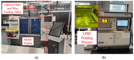
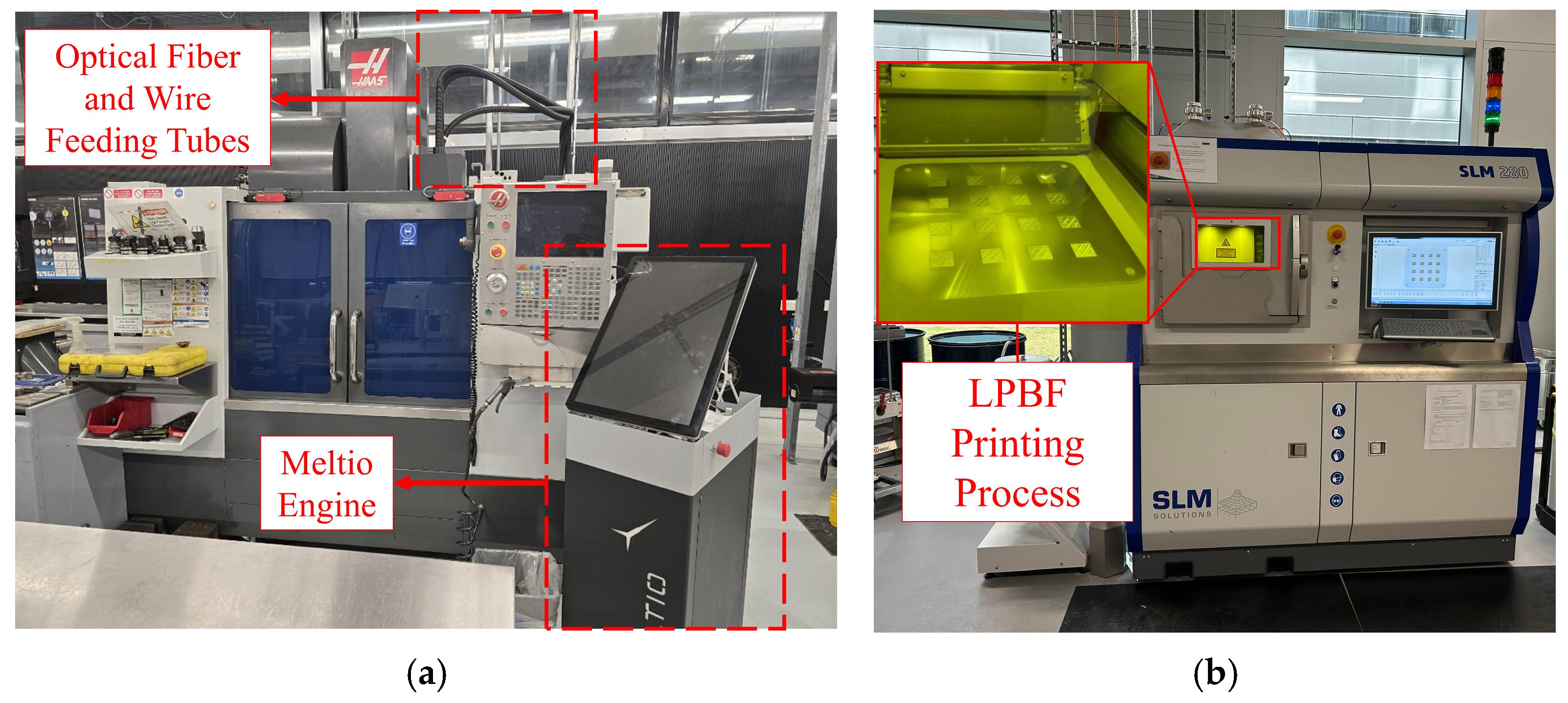
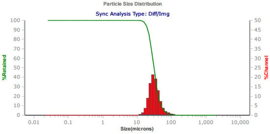
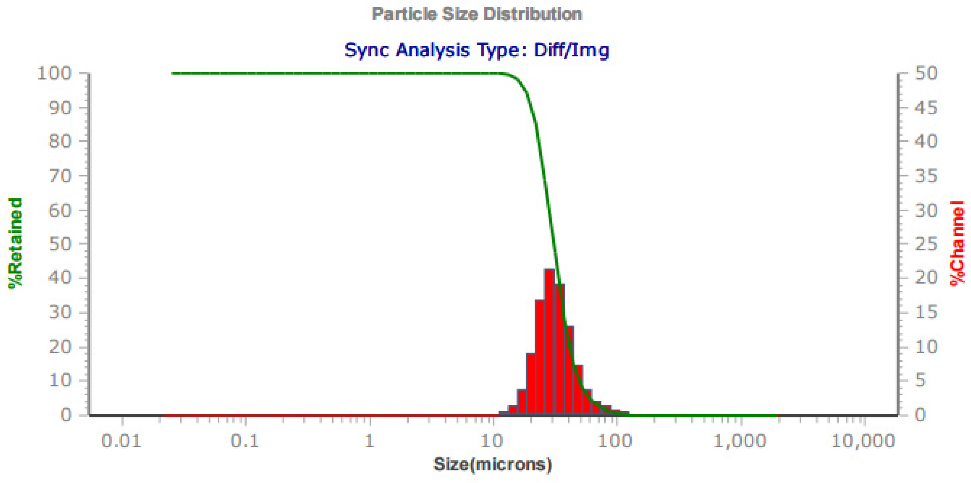
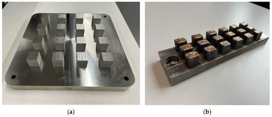
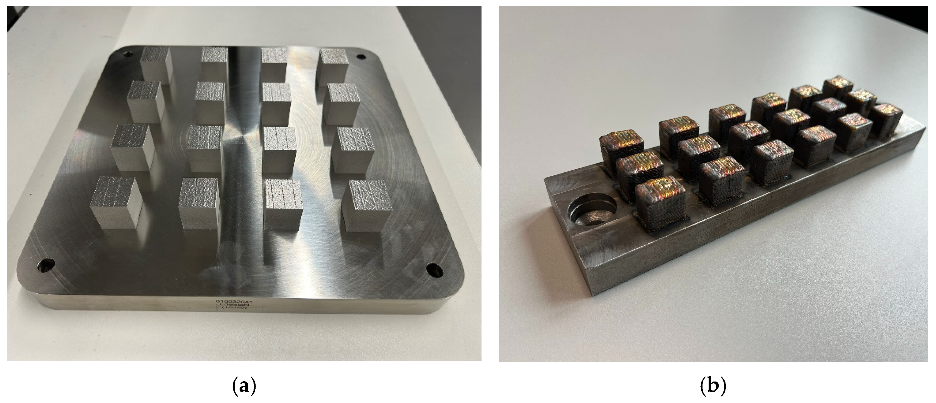
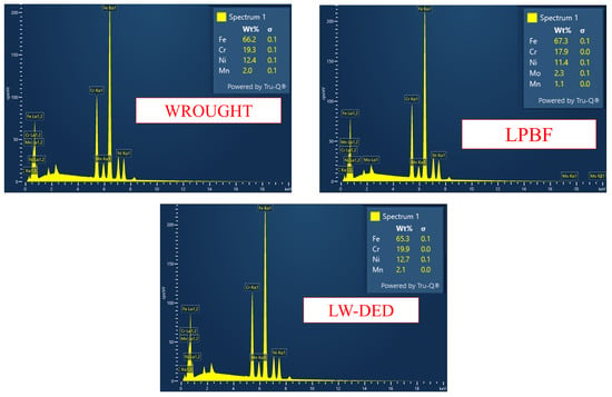
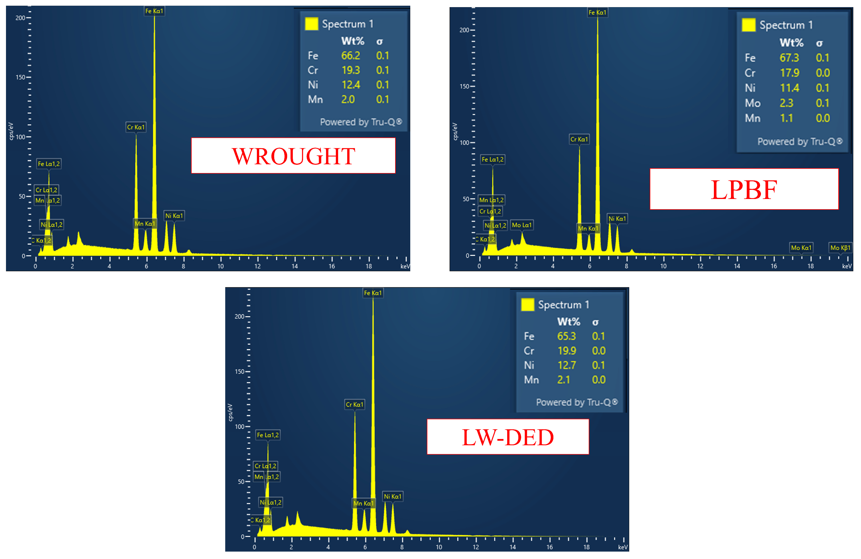
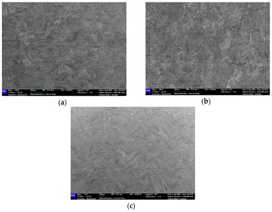
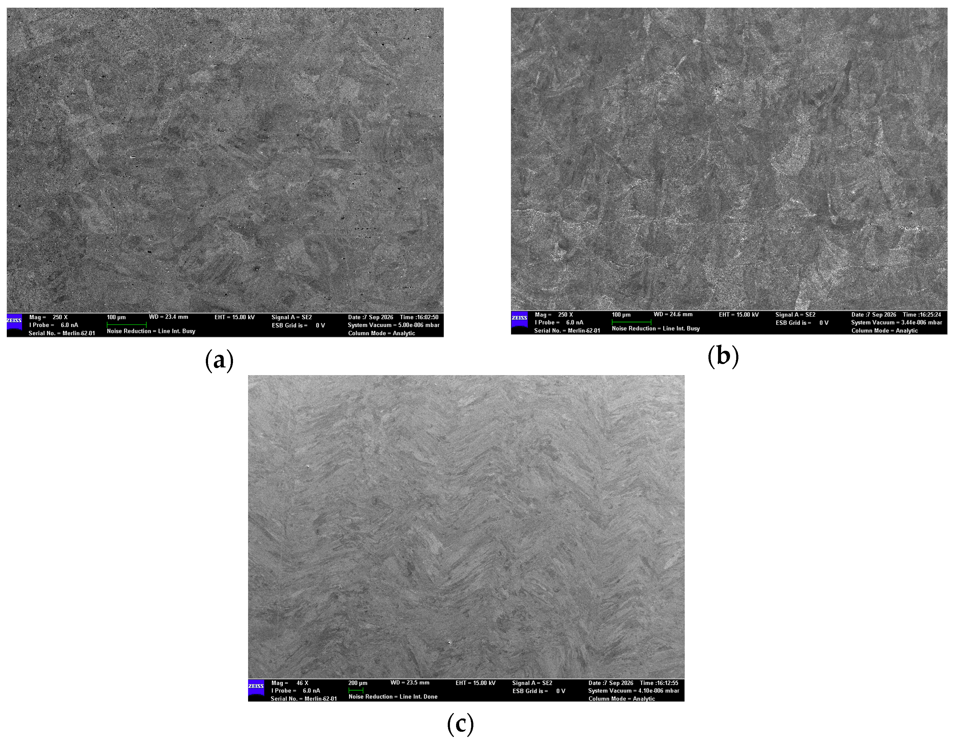
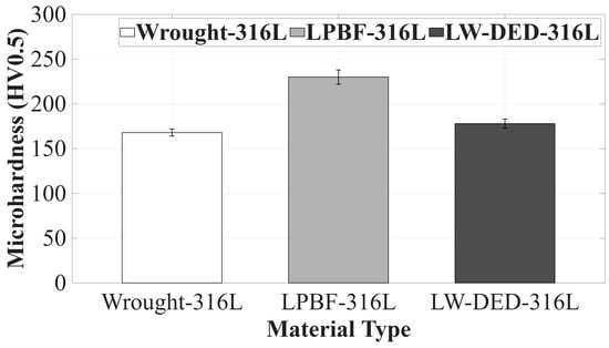
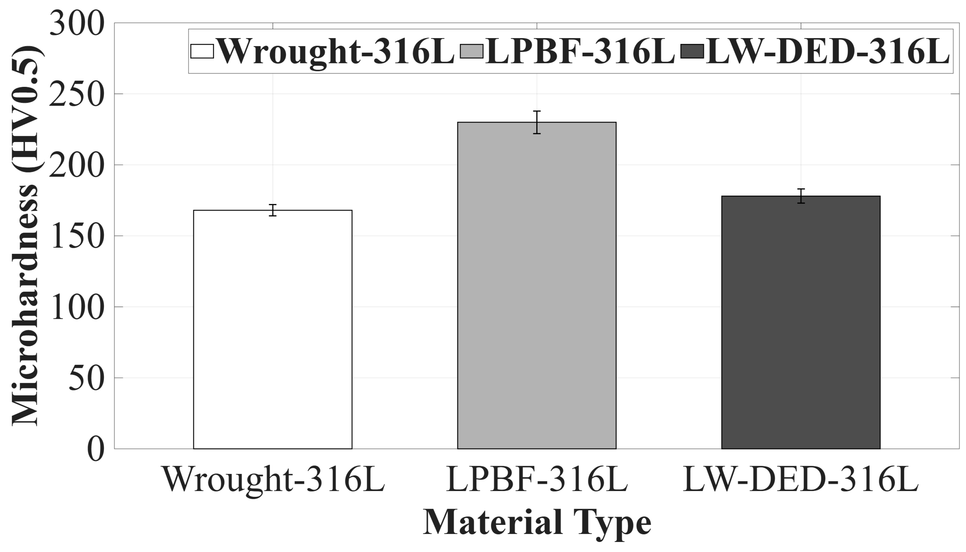
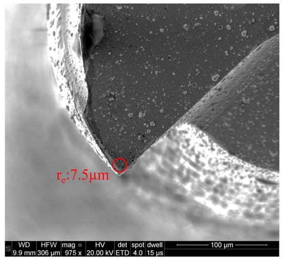
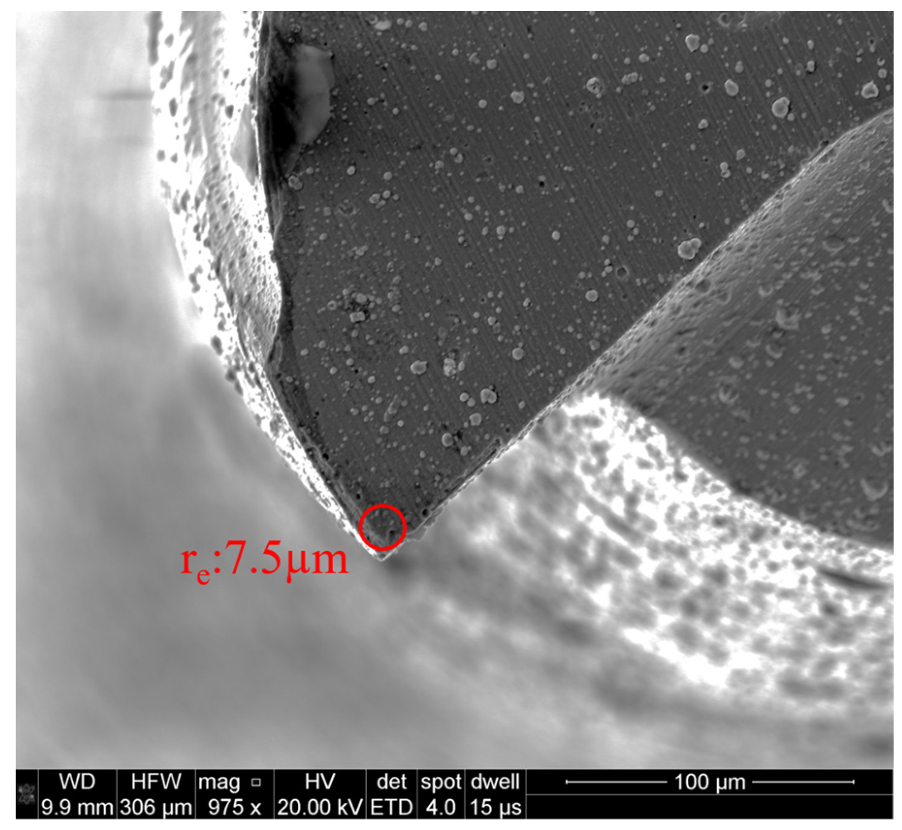
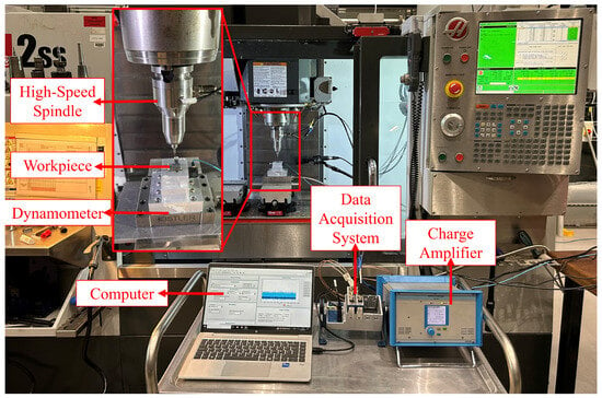
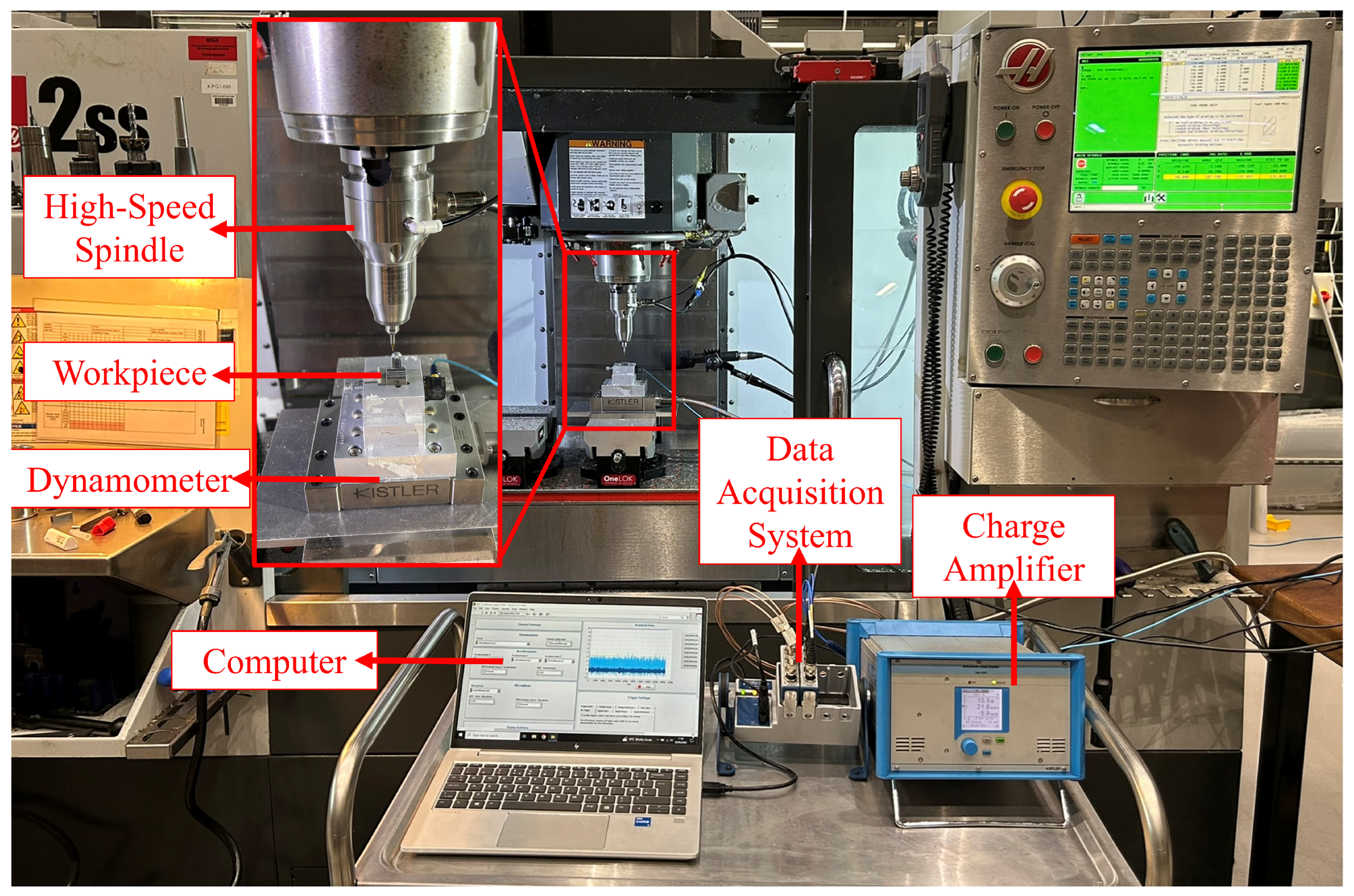
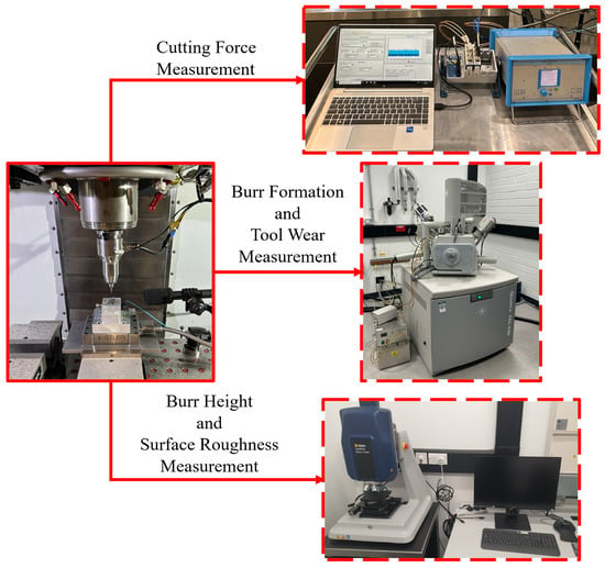
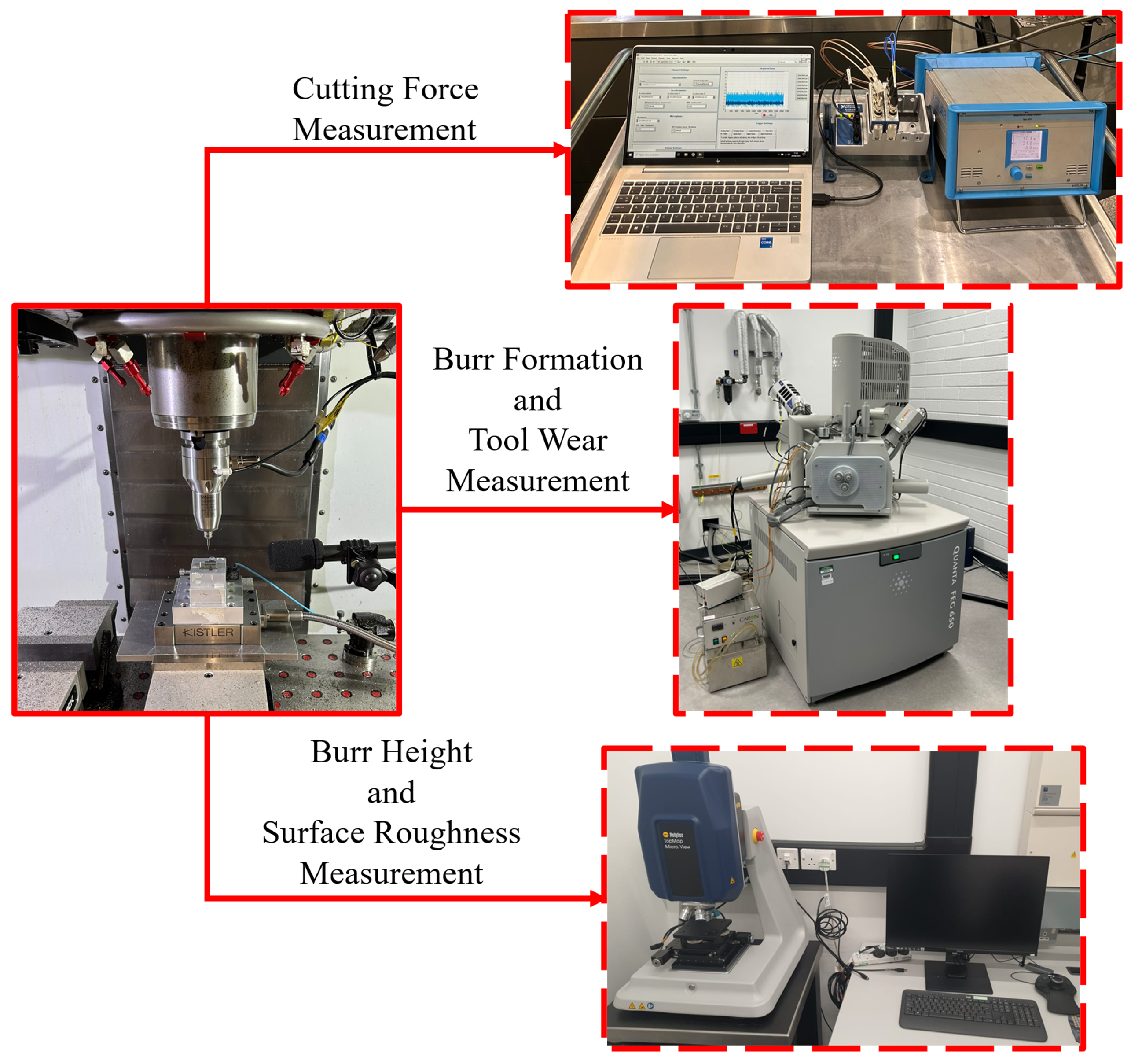
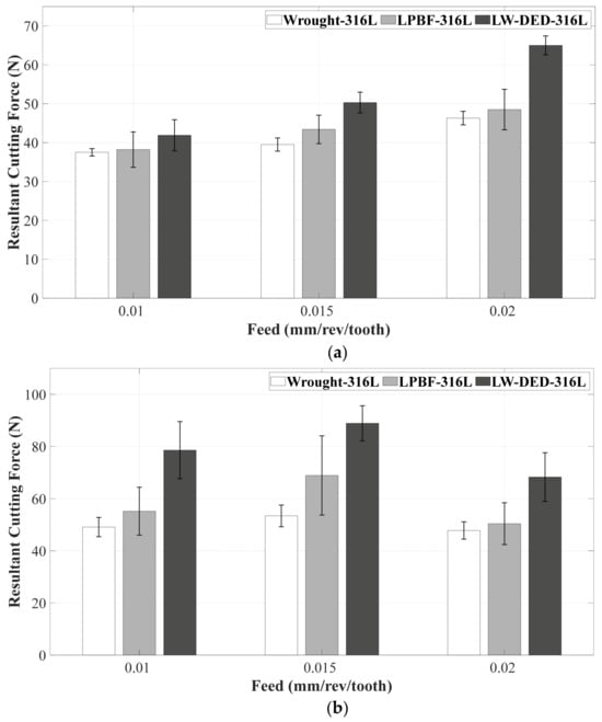
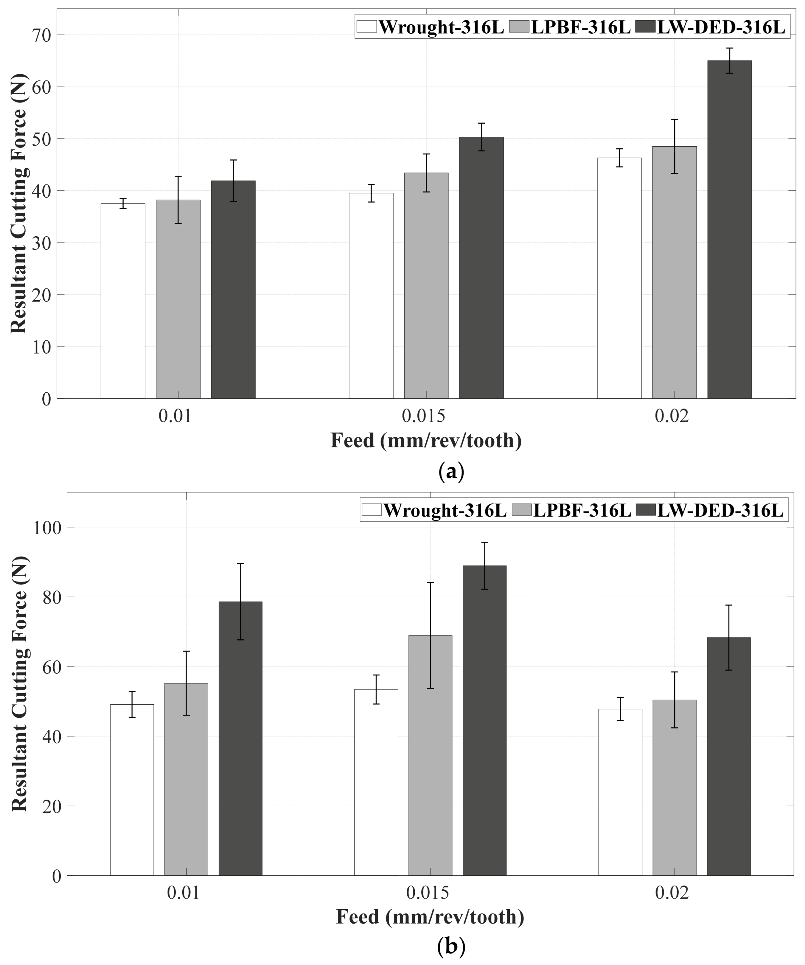
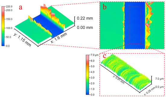
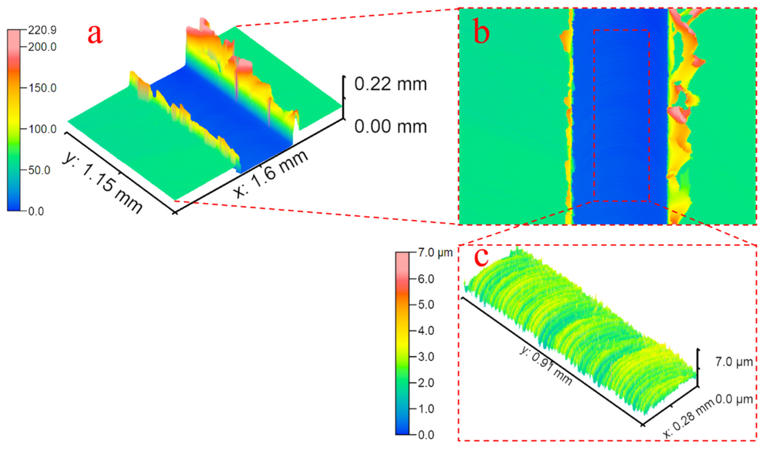
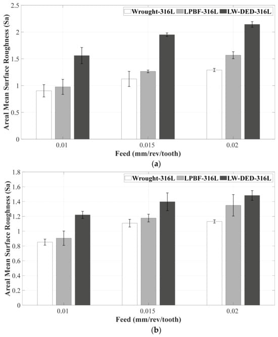

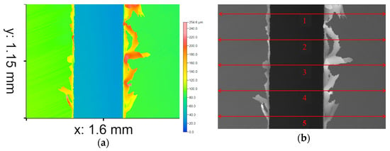
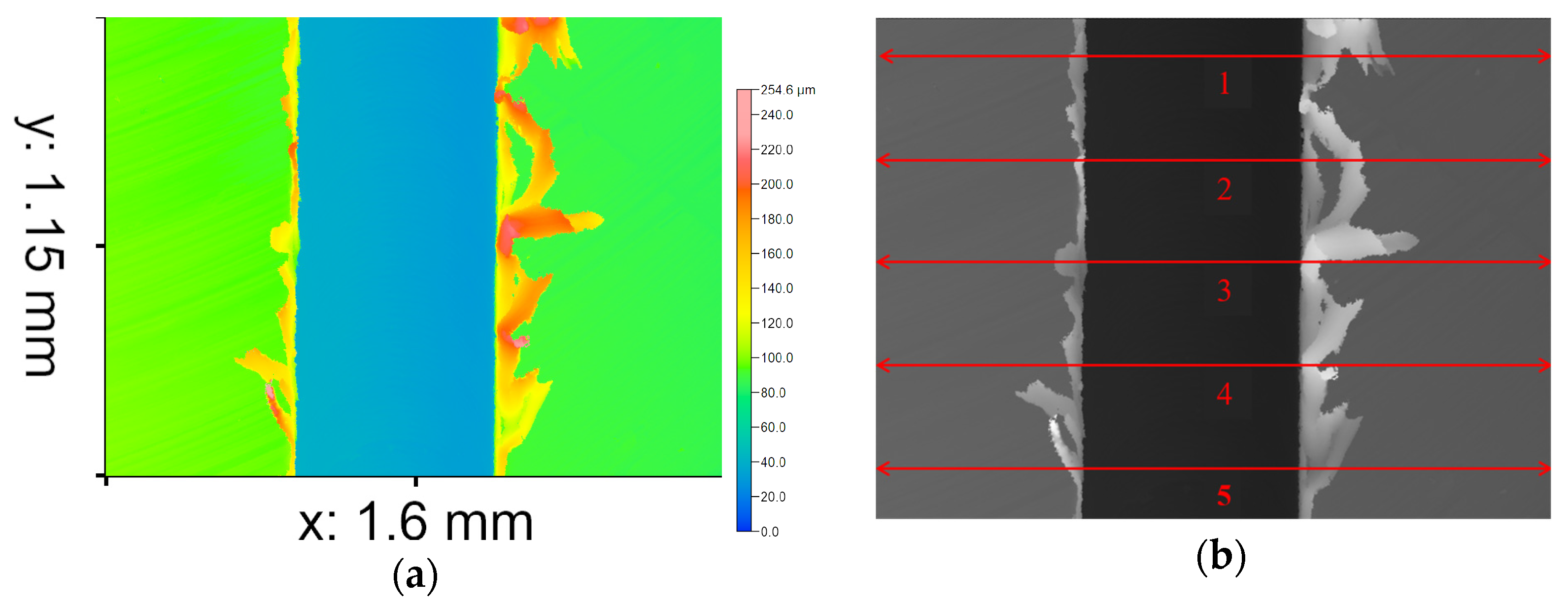
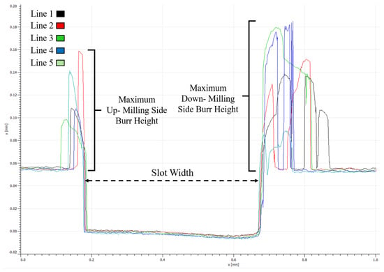
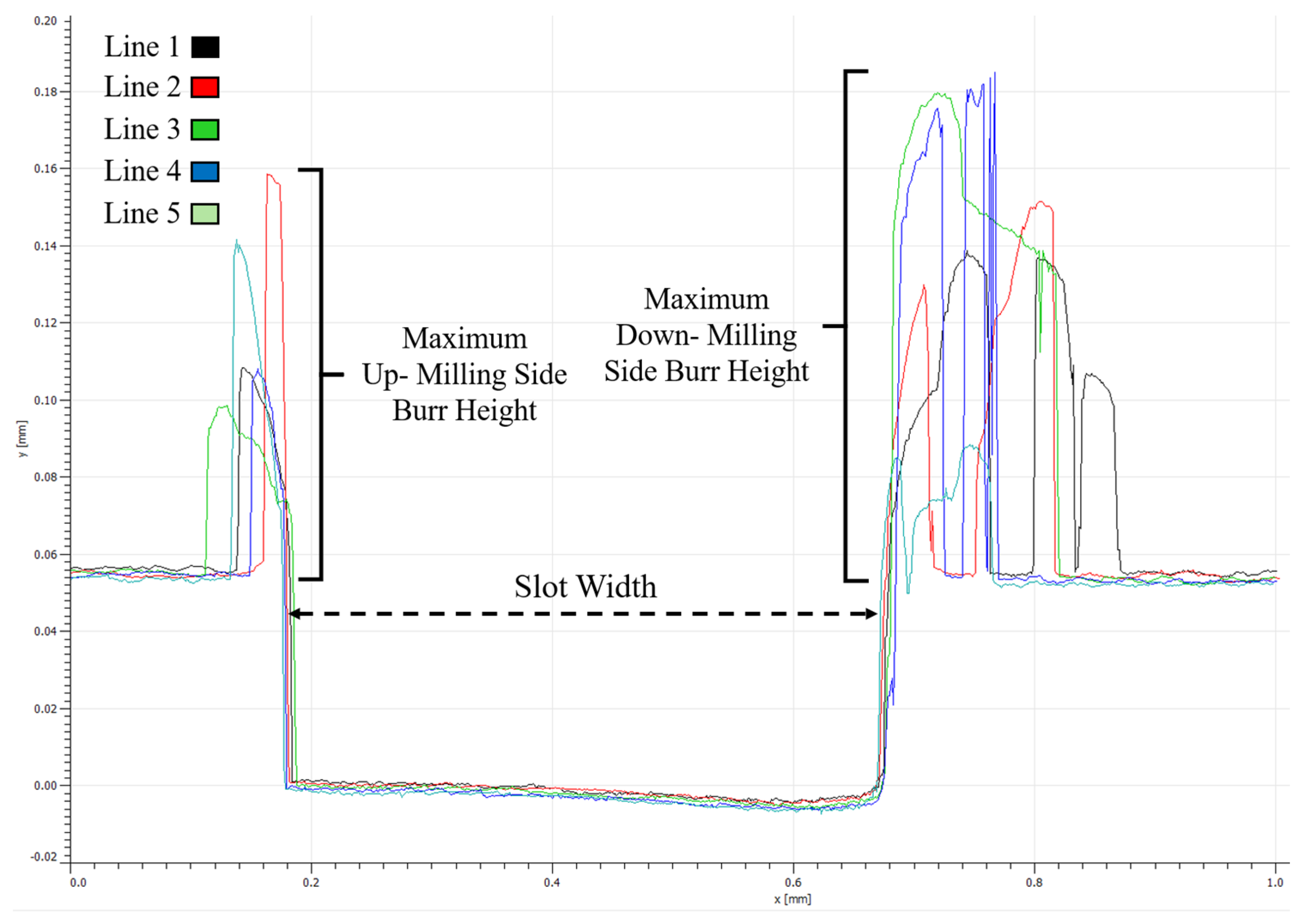
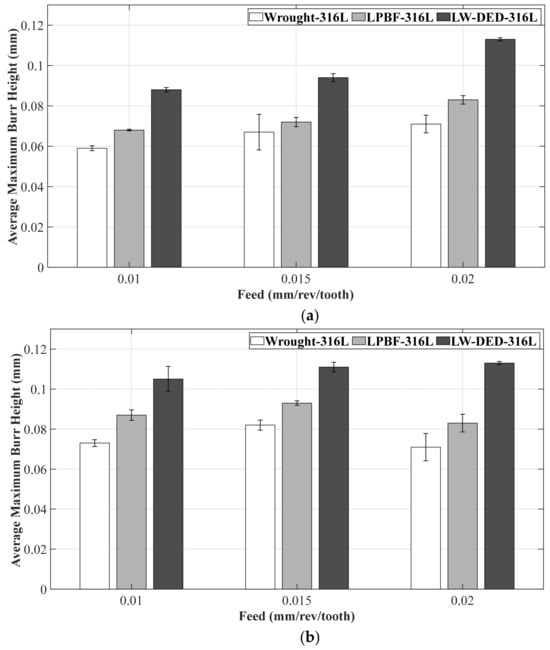
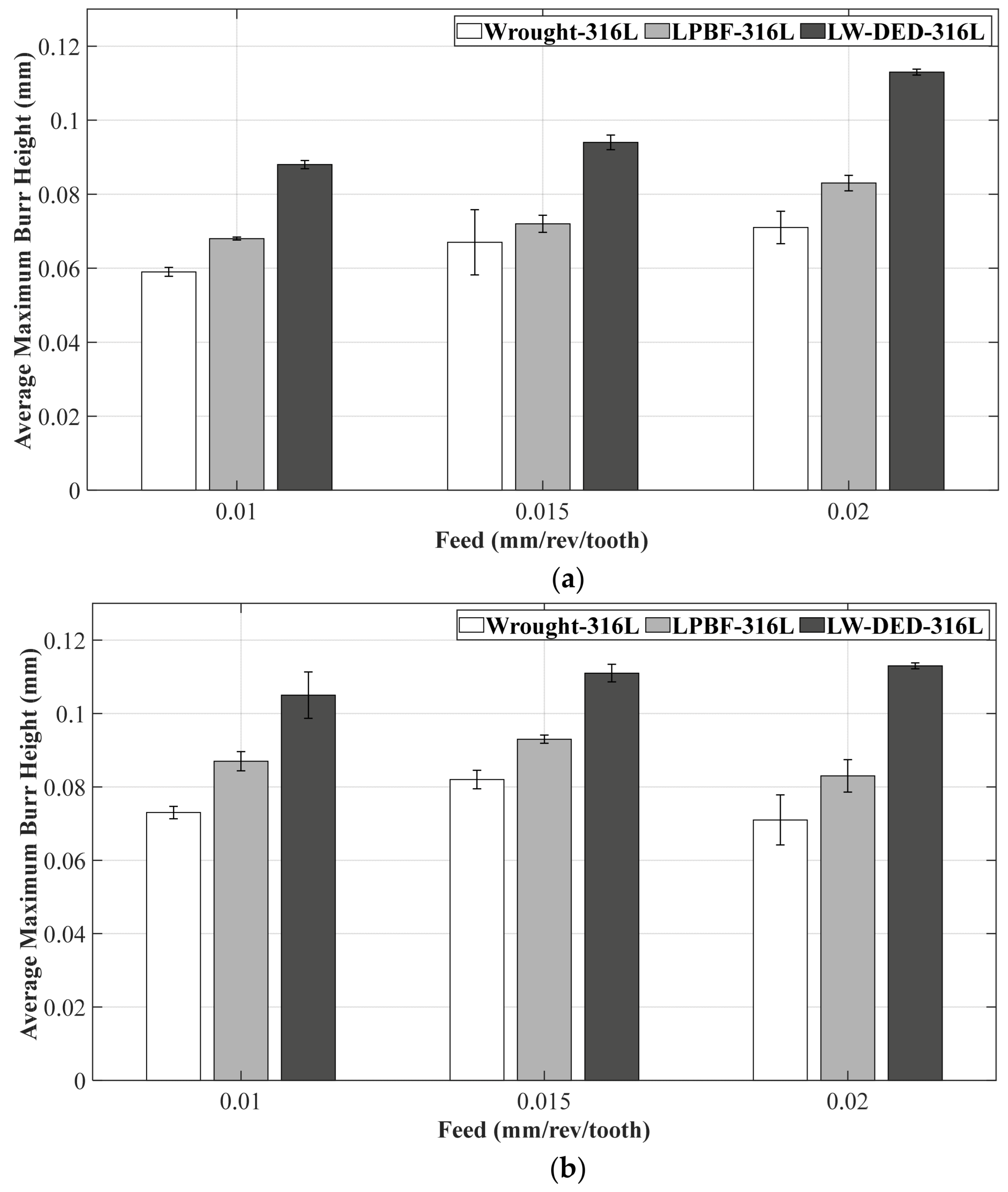
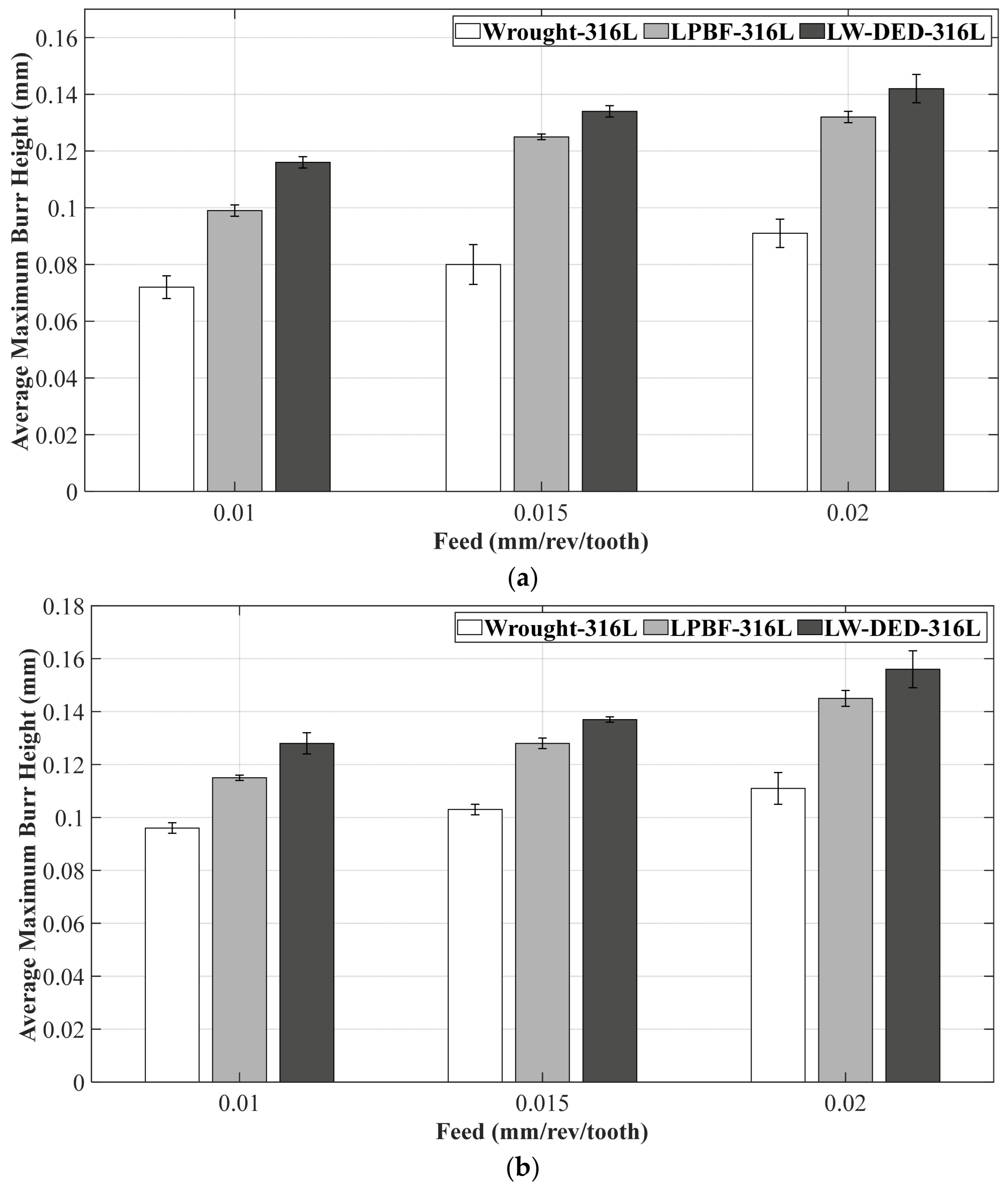
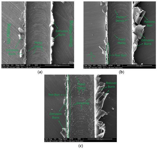
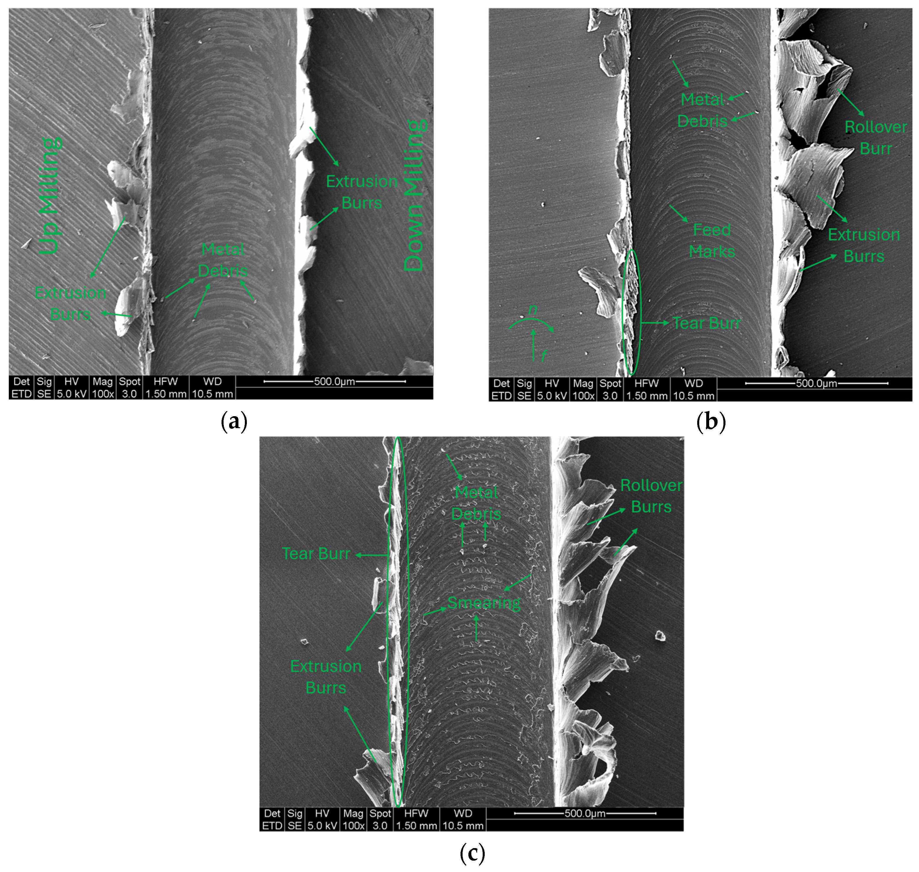
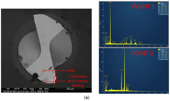
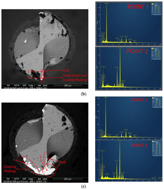
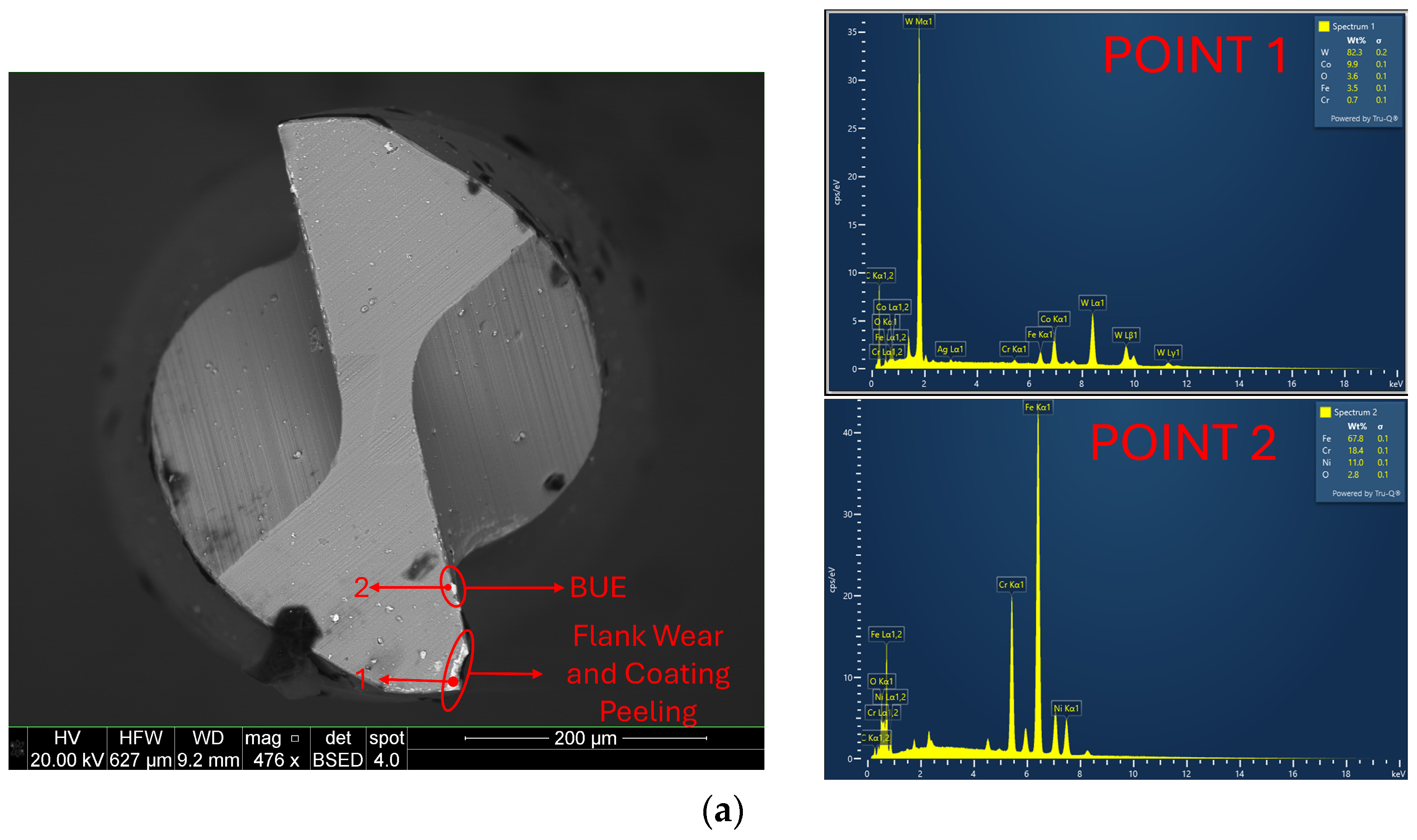
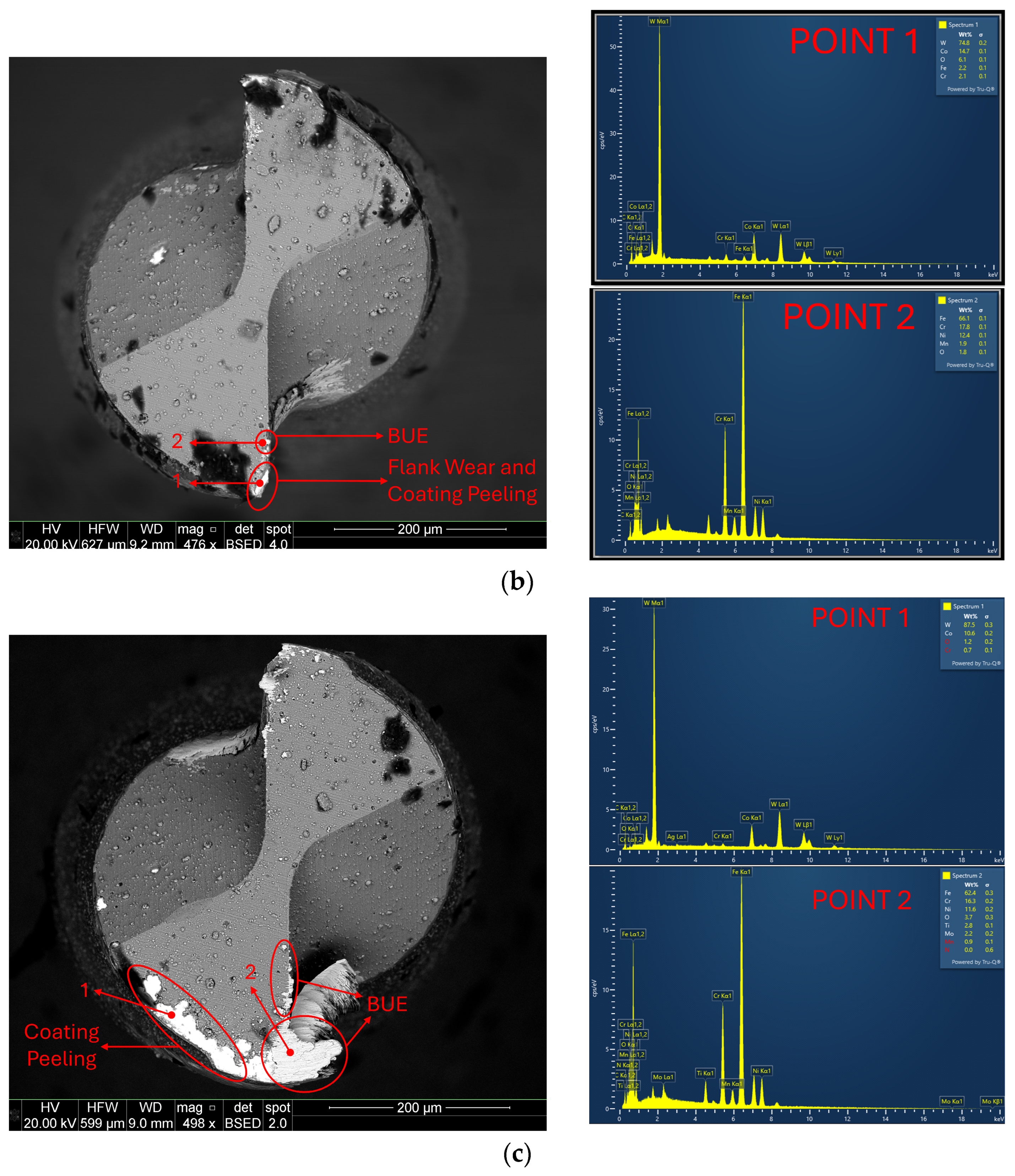
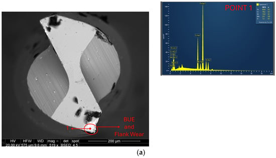
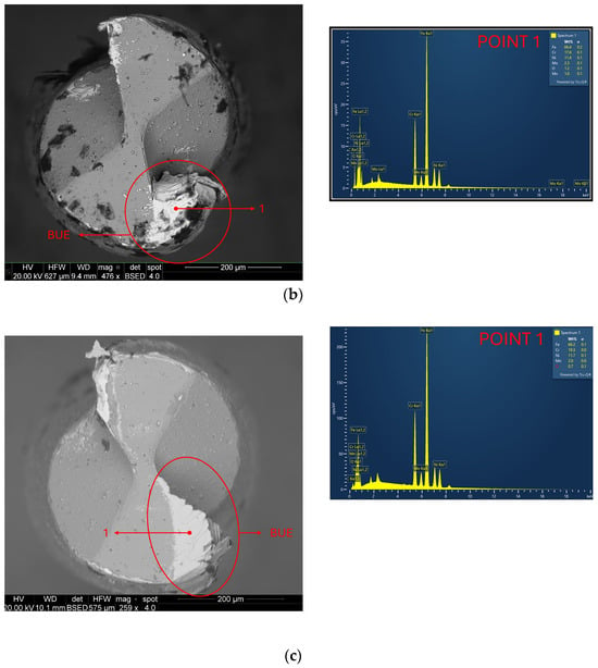
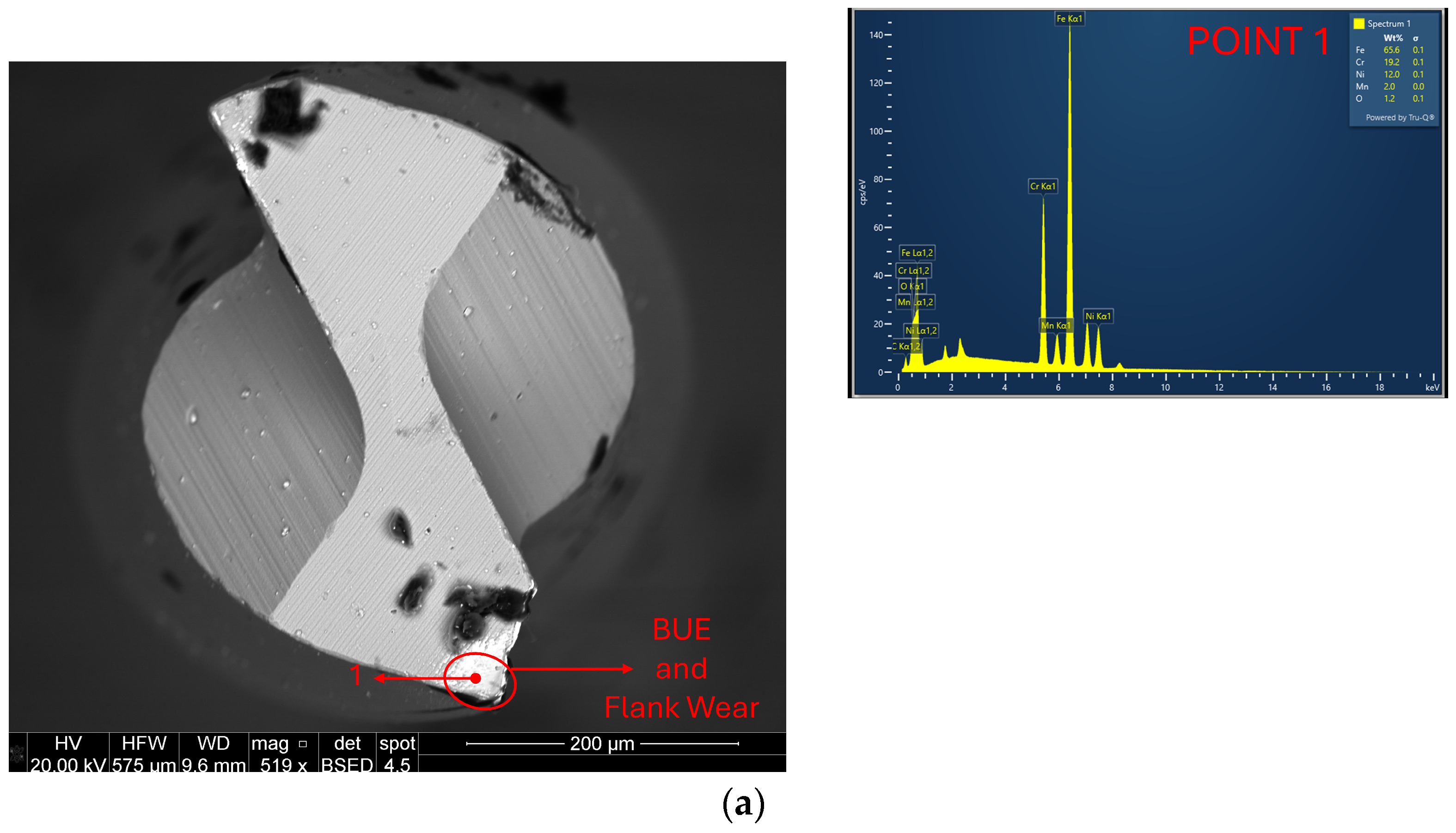
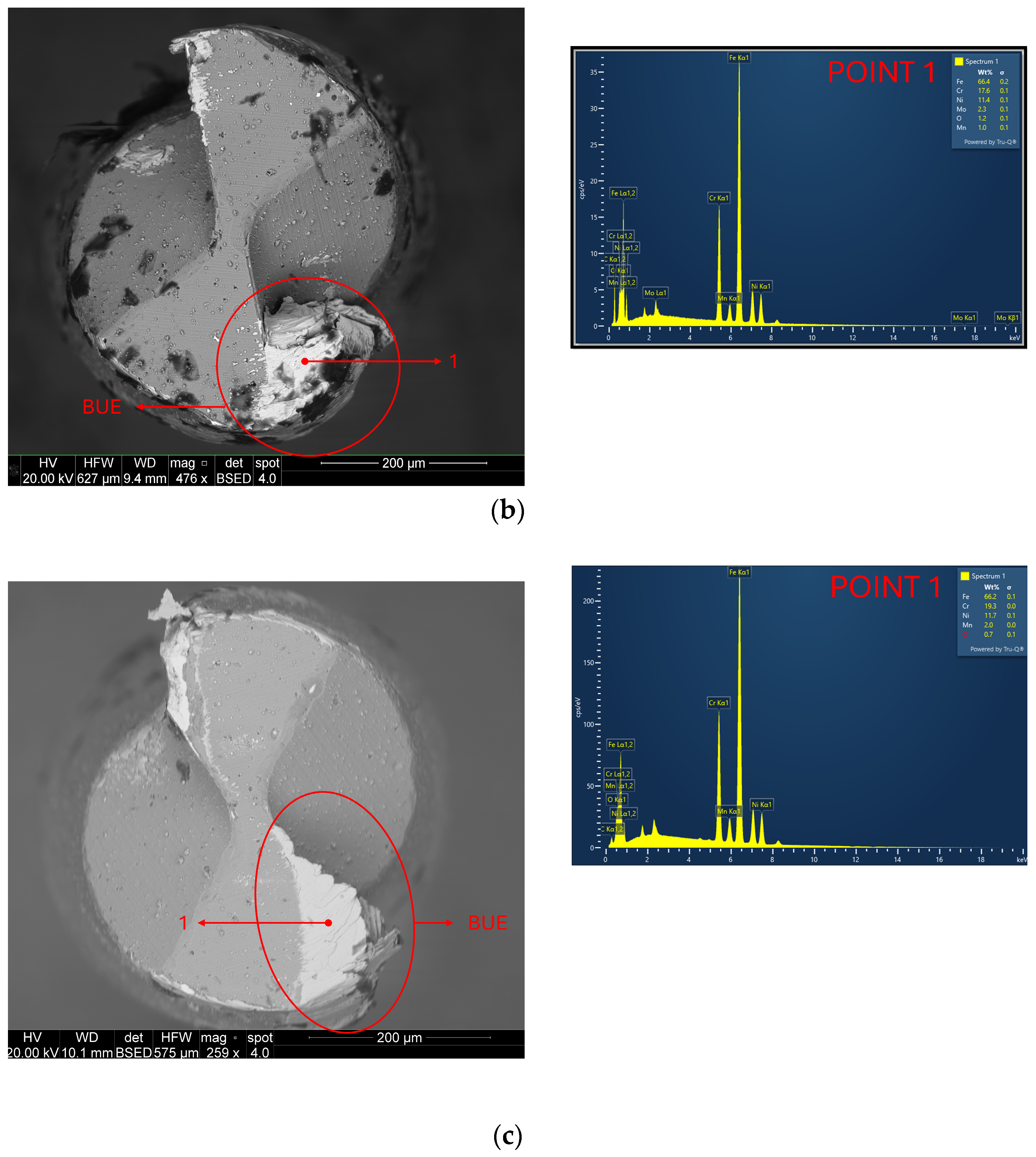


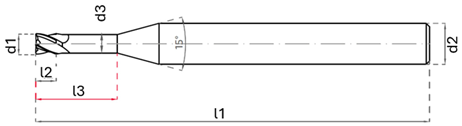
Disclaimer/Publisher’s Note: The statements, opinions and data contained in all publications are solely those of the individual author(s) and contributor(s) and not of MDPI and/or the editor(s). MDPI and/or the editor(s) disclaim responsibility for any injury to people or property resulting from any ideas, methods, instructions or products referred to in the content. |
© 2026 by the authors. Licensee MDPI, Basel, Switzerland. This article is an open access article distributed under the terms and conditions of the Creative Commons Attribution (CC BY) license.