


Abstract
This study considers a robust design methodology to reduce cogging torque in the EPS (Electric Power Steering) of an automotive system. Cogging torque reduction is the key design factor to improve steering feeling and drive stability in an EPS system. For this reason, an SPMSM (Surface Permanent Magnet Synchronous Motor) has been widely applied to drive a motor in an EPS system. Furthermore, two design methods, which are a magnet shape and step-skew design for rotor assembly, have been mainly used to reduce cogging torque in an SPMSM. In this paper, an SPMSM is selected as the drive motor and a robust design methodology is proposed to reduce cogging torque in an EPS system. Firstly, a cycloid curve is used for the magnet shape to reduce cogging torque. An evaluation index δq is also used to compare this with a conventional magnet shape design. Secondly, based on the results of the magnet shape design with the cycloid curve, a step-skew design for rotor assembly is also applied to reduce cogging torque. In order to validate the effectiveness of the robust design for the cycloid curve and conventional magnet shape with rotor step-skew, the results from FEM (Finite Element Method) analysis and prototype tests are compared. The cycloid curve magnet shape model with rotor step-skew was verified to reduce the cogging torque and enhance the robustness for cogging torque variation through the analysis and protype test results. The verified results for the proposed model will be extended to meet the required cogging torque variation for the various applications driven by SPMSM with the robust design model.
1. Introduction
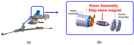
As the regulations for CO2 reduction and fuel efficiency improvement increase, electrified systems have been widely used, such as power train and chassis systems [1,2,3,4]. In electrified systems in vehicles, EPS (Electric Power Steering) is the most representative electrified system in chassis systems as shown in Figure 1 [5,6]. In an EPS system, a PMSM (Permanent Magnet Synchronous Motor) has been mainly used due to its high torque density and efficiency [7].
Figure 1.
EPS (Electric Power Steering) system in vehicle: (a) configuration of EPS system; (b) SPMSM (Surface Permanent Magnet Synchronous Motor) used in EPS system.
However, cogging torque reduction is the key design quality factor to enhance steering feeling and driving stability at high speed in EPS systems [8]. For this reason, an SPMSM (Surface Permanent Magnet Synchronous Motor) which has magnet outside its rotor core has been widely applied to reduce cogging torque, compared with an IPMSM (Internal Permanent Magnet Synchronous Motor) which has magnets inside its rotor core. Compared with SPMSM, IPMSM has disadvantages for reducing cogging due to the saliency of the rotor structure [9].
Cogging torque is a torque pulsation due to the magnetic resistance change when a motor rotates under a no-load drive condition. This cogging torque depends on the shapes and material properties of the rotor, stator, and magnet [10,11]. For this reason, design methods to reduce cogging have been reported extensively in various ways. Previous studies for cogging torque reduction are mainly classified into magnet shape and skew design for the rotor assembly of SPMSMs used in EPS systems. In the case of magnet shape design, applying eccentricity to the magnet shape has been widely used to improve cogging torque reduction [12,13,14].
In addition to the magnet shape design, skew design for cogging torque reduction is classified into continuous and step-skew. Although continuous skew has more strength than step-skew for reducing cogging torque, the step-skew design for rotor assembly has been used in the mass production of EPS systems due to its reduced manufacturing costs [15,16,17,18,19,20]. Generally, the combination design of an eccentric magnet shape and step-skew for rotor assembly have been applied [21].
In previous studies, cycloid curves have been widely used for mechanical fields, e.g., speed reducers and oil pumps to transfer mechanical power [22,23,24]. However, in the study by Park et al. [25], the cycloid curve was adopted for the magnet shape of an SPMSM. In their study, it was also validated that cogging torque was reduced for the SPMSM. However, the combination method of a cycloidal curve for the magnet shape and step-skew design is not reported and its effectiveness is also not verified.
Furthermore, a robust design has been strictly required to guarantee the quality and reliability of motors after mass production in the automotive field [26,27,28]. In particular, a robust design has been strictly implemented to meet the required variance of cogging torque considering manufacturing disturbances for mass production [29,30,31].
In this study, a cogging torque reduction design is mainly addressed to improve the steering feeling and drive stability in an EPS system. A cycloid curve for the magnet shape is used to reduce the cogging torque in a combination method with rotor step-skew design. Based on the same rotor step-skew design, an evaluation index δq is used and determined to compare the proposed and conventional magnet shape design. The robust design with cogging torque reduction for the proposed and conventional models is compared and verified through analytical methods and prototype tests are analyzed using numerical methods.
This study will be organized as follows. In Section 2, the analysis model, the SPMSM type with six poles and nine slots for the research model, and the specifications and conventional model for the eccentric curve for the magnet shape are described. In Section 3 the proposed model for the magnet shape, the proposed model with a cycloid curve on the magnet, the non-skew and step-skew models, and numerical analysis results are described. Finally, prototype test results of cogging torque for the conventional and proposed model are described in Section 4, whereas Section 5 comprises the conclusions.
2. Analysis Model
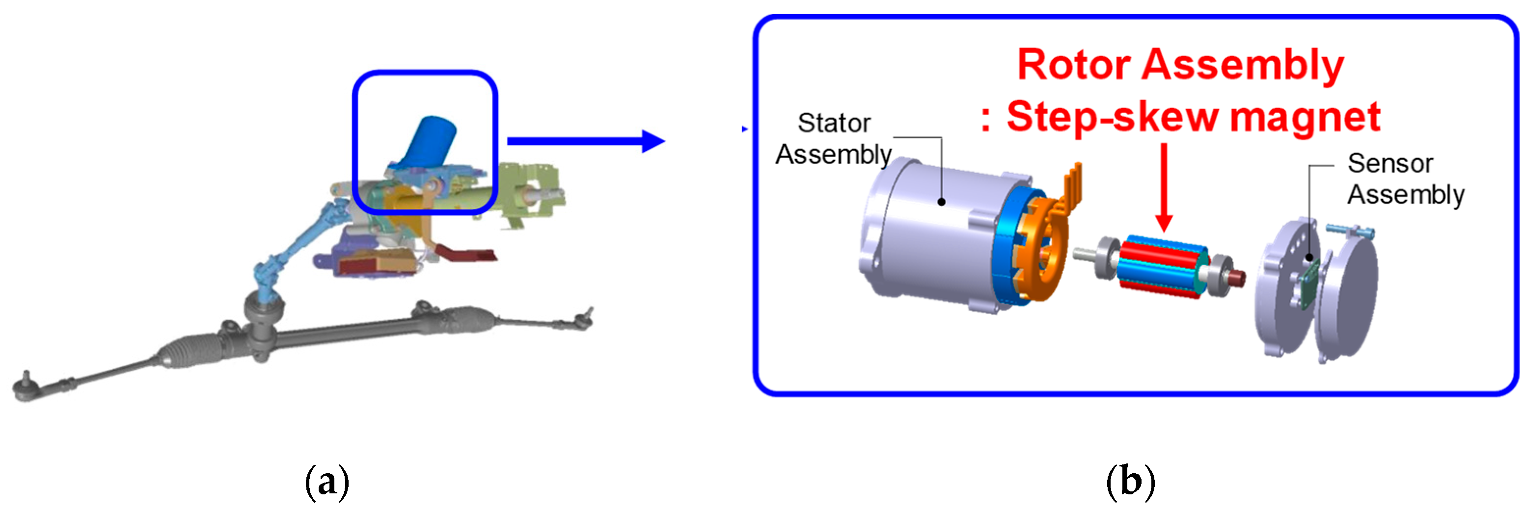
In this study, the motor type is an SPMSM, as shown in Figure 2. Figure 2a and b also show the cross-sectional view of the stator and rotor cores in Figure 1 respectively. The numbers of slots and poles in this study are 9 and 6, respectively. In the case of Figure 2b, the numbers of poles is 2 with 1/3 model of rotor core which is equivalent to 6 poles. Table 1 shows the detailed specifications of the stator and rotor cores, as shown in Figure 2.
Figure 2.
Stator and rotor cores for analysis model: (a) stator core with 9 slots; (b) rotor core and magnet with 2 poles (1/3 model).
Table 1.
Main specification for analysis model.
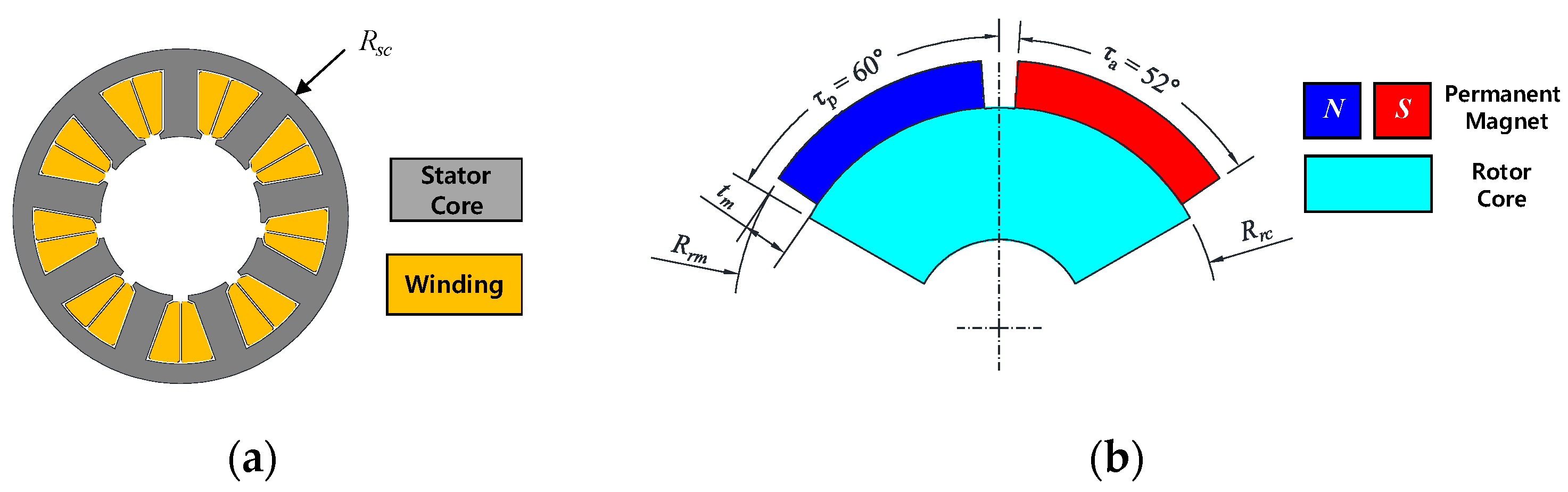
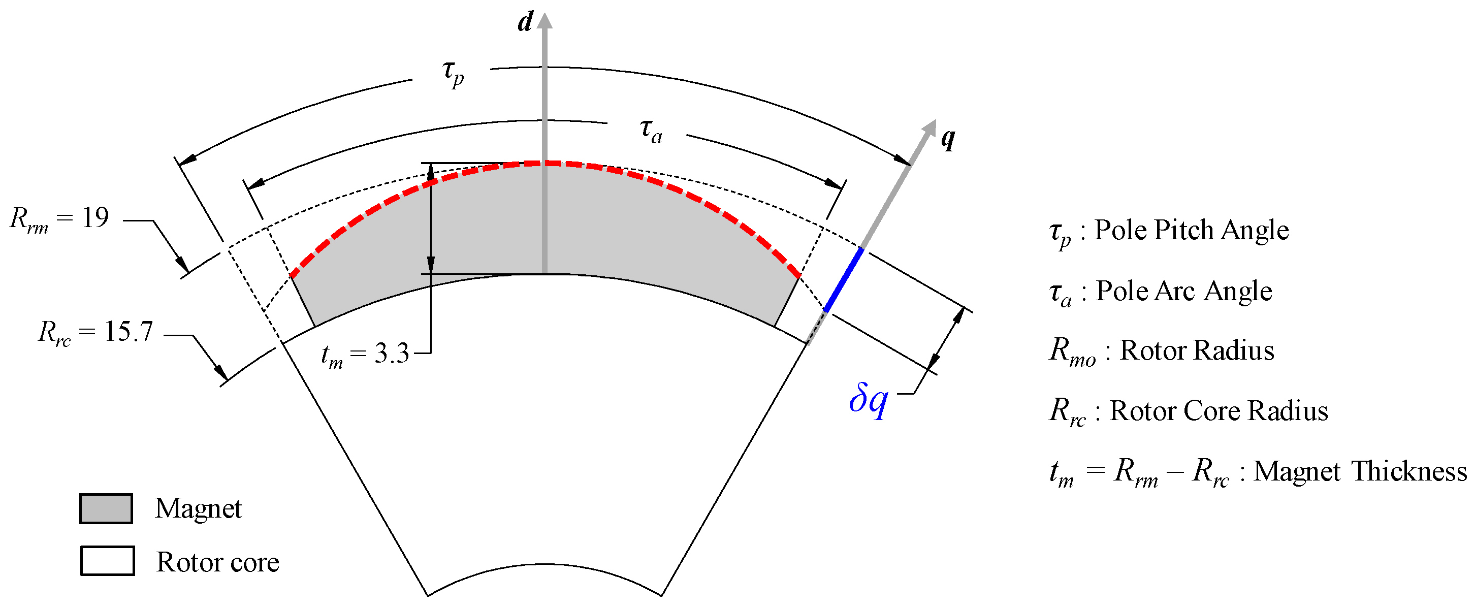
Based on the specification of the analysis model, as shown in Figure 2 and Table 1, an evaluation index δq is used to compare the proposed and conventional magnet curve, which is expressed as the red dotted line in Figure 3. δq is the air gap length on the q axis that is electrically at 90 degrees to the axis of the center axis, the d axis, which is the magnetic flux of the rotor magnet. The length of δq is described in Figure 3. In this paper, δq (blue solid line in Figure 3) is defined as the distance from the intersection point of the extended curve for the magnet shape (red dotted line in Figure 3) and the q axis to the intersection point of the rotor outer radius Rrm and the q axis.
Figure 3.
Definition of δq to compare the proposed and conventional magnet curve.
3. Proposed Model for Magnet Shape
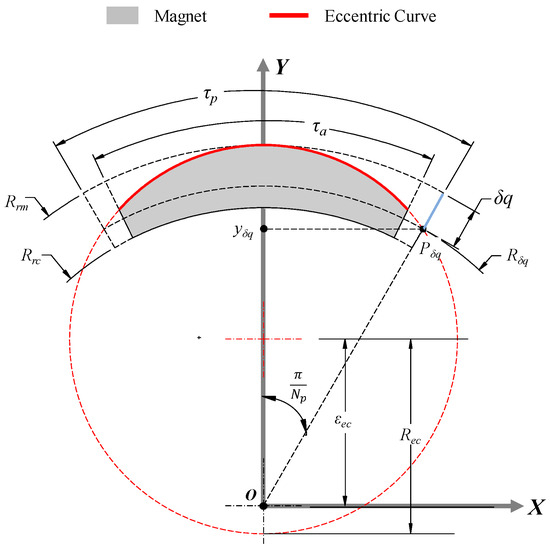
An eccentric curve has been generally used in the magnet shape of the SPMSM to reduce cogging torque and torque ripple [11,12]. In this study, an eccentric curve, which has an eccentricity from its center, is used to compare the proposed curve of the magnet shape, as shown in Figure 4. In order to apply the eccentric circle to the magnet shape, the known parameters are decided. The known parameters are δq, Rrm, tm, and Np (the number of poles). The unknown parameters of eccentric circle radius Rec and eccentricity εec can be calculated by using geometrical relationships, as shown in Figure 4 [13].
Figure 4.
Definition of eccentric curve for the conventional curve of the magnet.
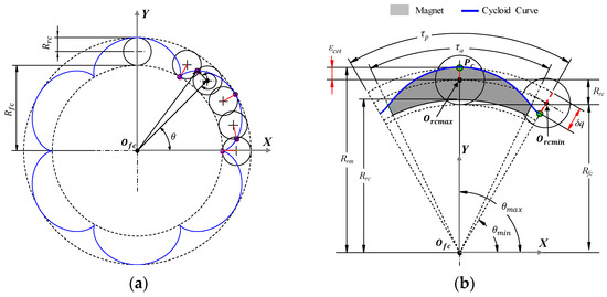
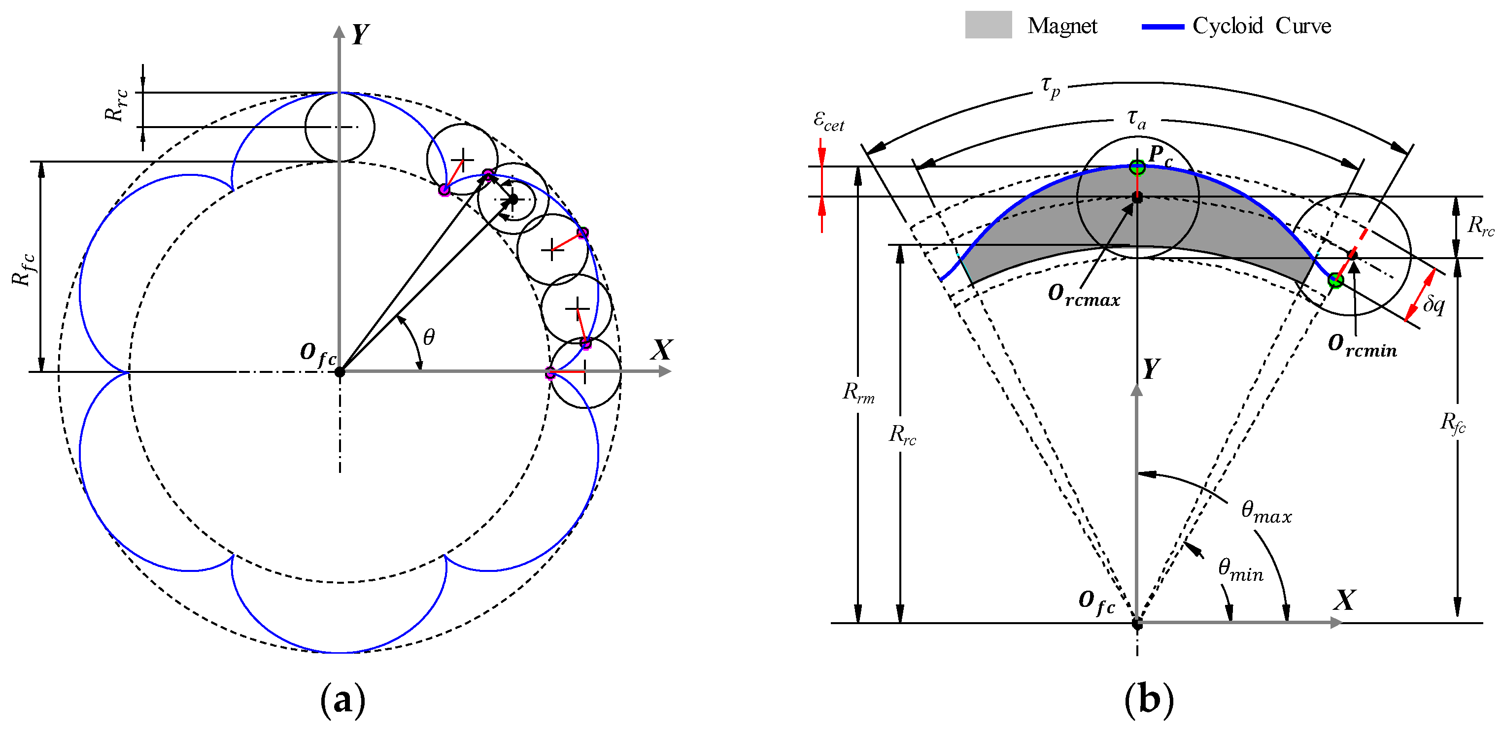
The proposed curve for the magnet shape is a cycloid curve. A cycloid is the curve traced by a point in or on rolling circle with radius Rrc as the rolling circle rolls along a fixed circle with radius Rfc without slippage, as shown in Figure 5a. In order to apply a cycloid curve to the magnet shape with the same procedure as an eccentric curve, the known parameters are also decided. The known parameters are those of the eccentric curve such as δq, Rrm, tm, and Np. The unknown parameters of Rfc, Rrc, and the eccentricity of cycloid curve εecc can also be calculated by using geometrical relationships, as shown in Figure 4 [25].
Figure 5.
Definition of cycloid curve for the conventional curve of the magnet: (a) trajectory of cycloid curve for 6 poles of rotor; (b) trajectory of cycloid curve of the magnet with 1 pole and δq.
Figure 5 shows the cycloidal curve trajectory of 6 poles of the magnet for the rotor model given in Figure 2b. In addition, Figure 5a shows the trajectory of the cycloid curve for 6 poles of the rotor without δq. In contrast to Figure 5a, Figure 5b shows the trajectory of the cycloid curve with a certain value of δq for 1 pole of the rotor.
Based on the design procedure of the conventional and proposed curve of the magnet for a given value of δq, the calculation of cogging torque is conducted. As described in Section 1, cogging torque is a torque pulsation due to the change in magnetic resistance at no-load drive. Generally, the equation of cogging torque Tcog is expressed in Equation (1) [12,13].
In Equation (1), θ is the rotational position of the rotor, Lstk is the stack length of the motor core, μair is the permeability of air, r is the radius of the rotor, 2π is 1 period of cogging toque pulsation, Br is the magnetic flux density in the radial direction, and Bθ is the magnetic flux density in the tangential direction. As described in Equation (1), the conventional and proposed method for the magnet is enabled to reduce cogging torque by reducing the harmonic magnitude and THD of the flux density waveform for Br and Bθ. Additionally, cogging torque also has the period of torque pulsation for a given number of poles and slots as shown in Equation (2).
In Equation (2), θcog is the mechanical angle of 1 period for cogging torque pulsation, Np and Ns denote the number of poles and slots, respectively, and LCM means the Least Common Multiple. In order to calculate cogging torque, the possible analytical method solution is shown in Equation (1). However, it is relatively difficult to calculate cogging torque due to the following factors. First, the non-linear properties of magnetic materials such as the permanent magnet and electric core. Second, the complex geometry of magnet shape such as the conventional and proposed curve. In this study, a numerical analysis of the FEM (Finite Element Method) is used in order to analyze cogging torque.
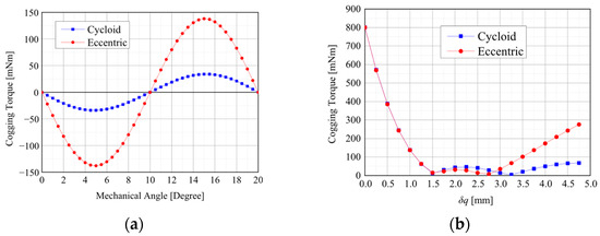
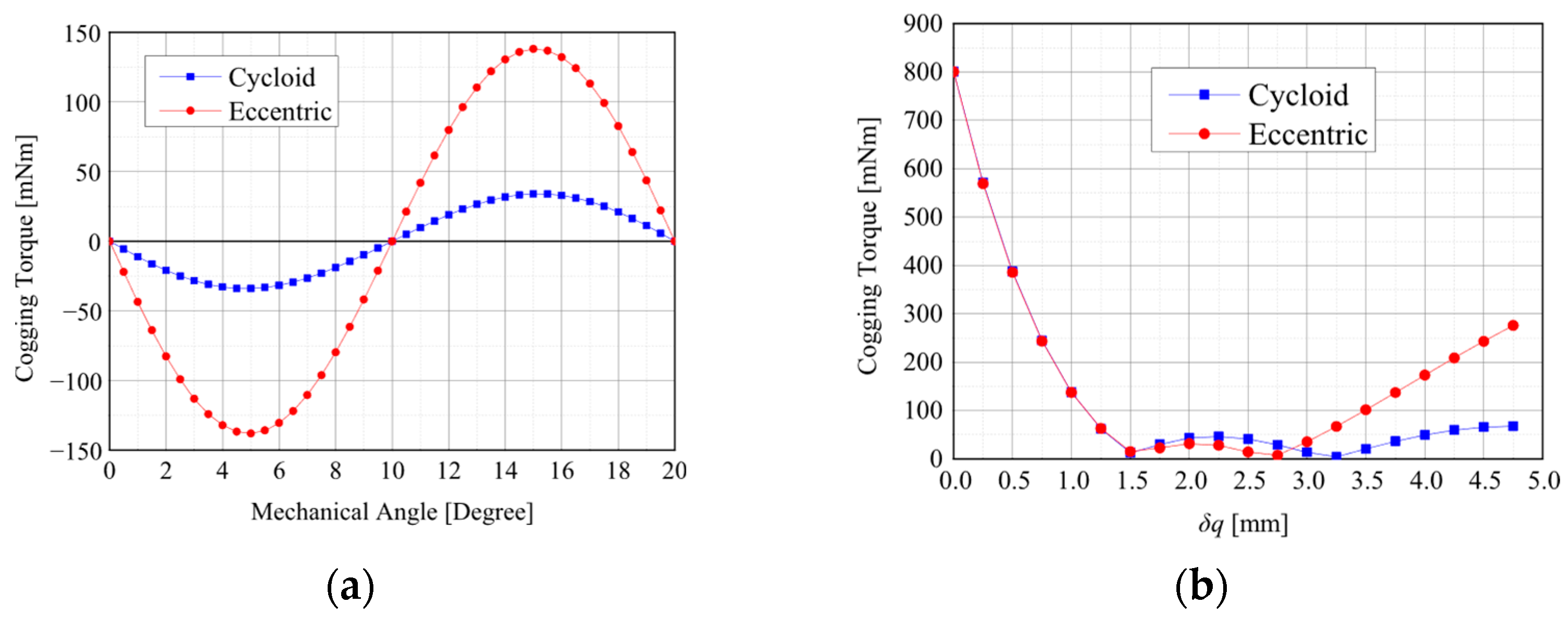
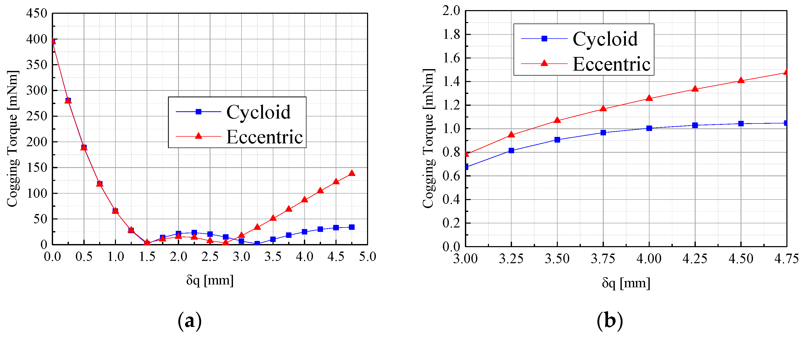
Figure 6 shows the calculation results of cogging torque. Figure 6a shows the wave-form of 1 period for cogging torque pulsation. As described in Equation (2), the mechanical angle of cogging torque θcog for Figure 6a is 20° at δq = 4.75 mm with 6 poles and 9 slots for this analysis model, as shown in Table 1. Figure 6b shows the peak-to-peak values of cogging torque at δq (0 ≤ δq ≤ 4.75).
Figure 6.
Calculation results of cogging torque: (a) wave-form of 1 period for cogging torque pulsation; (b) peak-to-peak values of cogging torque at δq (0 ≤ δq ≤ 4.75).
Based on the conventional and proposed curve of the magnet shape, the step-skew design, which is the method of cogging torque reduction, as explained in Section 1, is described to reduce cogging torque additionally. The step-skew angle θNskew is found by dividing by Nstep in Equation (2). Equation (3) shows the calculation of θNskew.
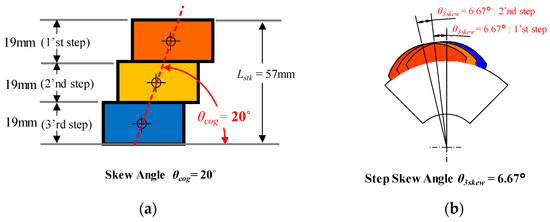
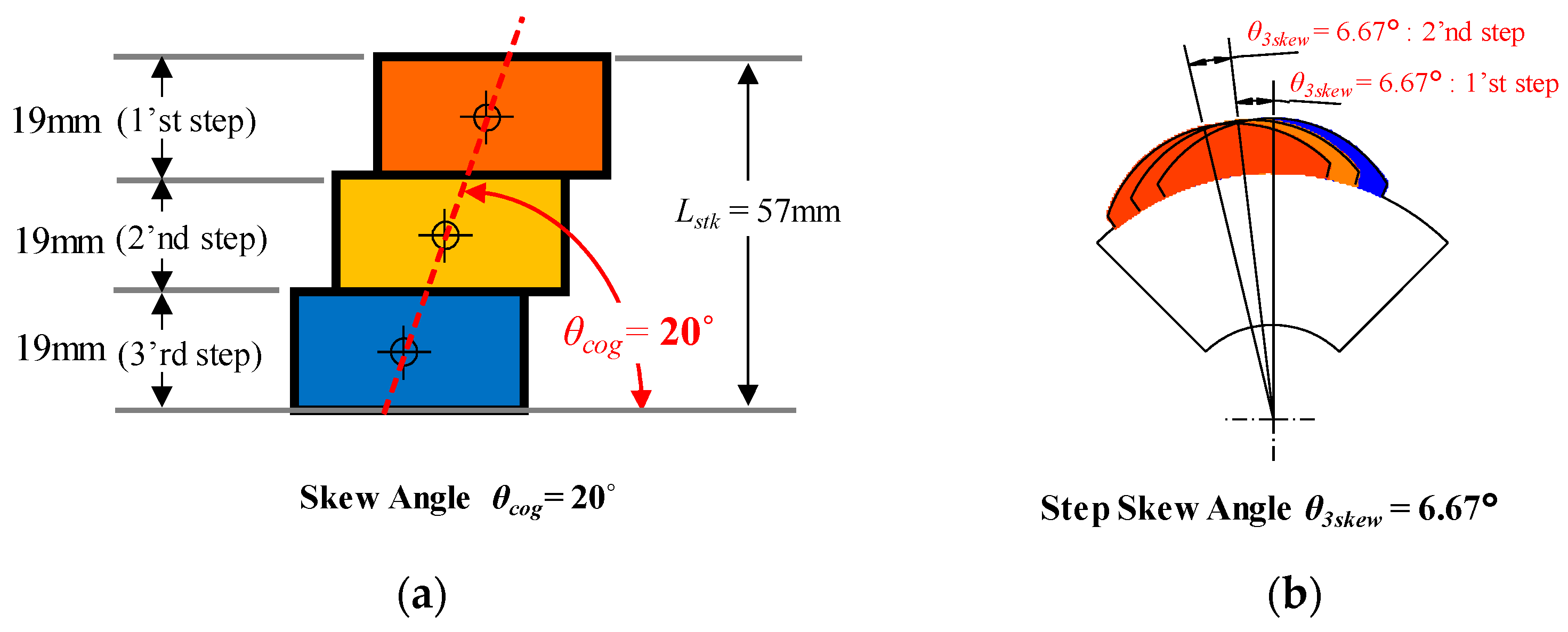
In Equation (3), Nstep is the number of steps and θNskew is the step-skew angle with Nstep. In this study, 3 step-skews, which have been widely used in EPS systems, is used to compare the conventional and proposed curve of the magnet shape [21]. Figure 7a and b show a skew angle θcog = 20° in Equation (2) and a step-skew angle θskew = 6.67° in Equation (3) with 6 poles and 9 slots for Lstk = 57 mm, respectively.
Figure 7.
Skew angle and step-skew angle for 6 poles and 9 slots: (a) skew angle θcog = 20°; (b) step-skew angle θ3skew = 6.67°.
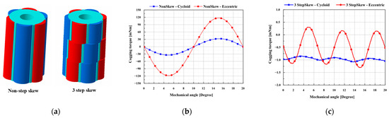
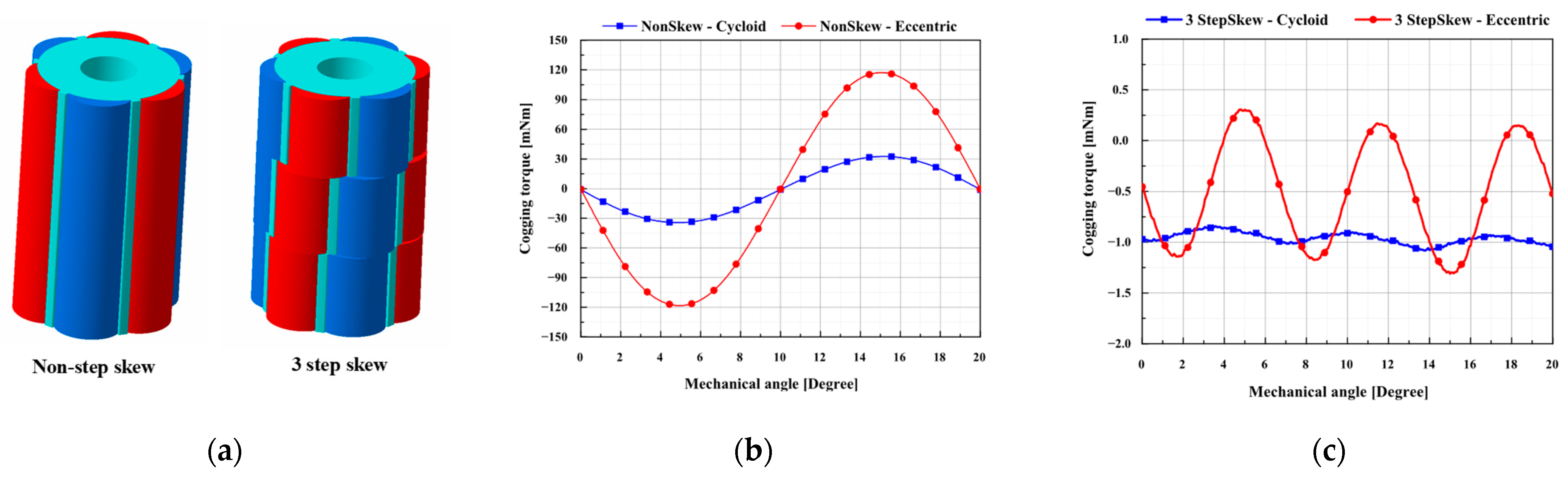
In this study, δq is selected as 4.5 by considering the performance variation due to the manufacturing tolerances or deteriorations. Three-dimensional models for the cycloid curve on the magnet shape are shown in Figure 8a and with 3 step-skews in Figure 7. In Figure 8b and c, the waveforms of 1 period for cogging torque pulsation are shown for the non-skew and 3 step-skews models of the eccentric and proposed curves at δq = 4.5, respectively.
Figure 8.
3 step-skew model and calculation results: (a) 3D models of non-step-skew and 3 step-skews for the cycloid curve at δq = 4.5; (b) wave-forms of cogging torque for non-skew model at δq = 4.5; (c) wave-forms of cogging torque for 3 step-skew model at δq = 4.5.
Table 2 shows the peak-to-peak values of cogging for the various step-skew models with the eccentric and cycloid curve of the magnet δq = 4.5. Based on the numerical analysis results, the effectiveness of step-skew models for the cogging torque reduction is validated on both the eccentric and cycloid curve models of the magnet.
Table 2.
Cogging torque analysis results for the step-skew models with δq = 4.5.
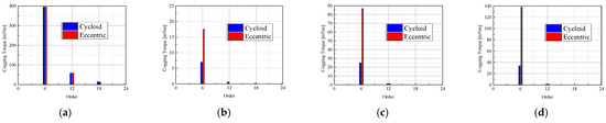
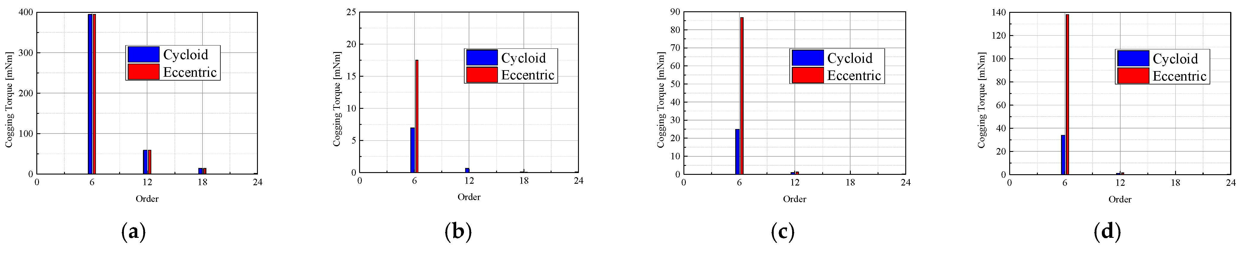
In order to explain the effective cogging reduction mechanism for the cycloid curve of the magnet, order analyses are conducted for the eccentric and cycloid curve of the magnet with the non-skew step rotor. The electric fundamental order of the PMSM with 6 poles and 9 slots in Table 1 is the 6’th order for the 360 mechanical degree. In addition to the fundamental order, the 6n’th orders with the positive integer value n are also generated. Figure 9 shows the order analysis results of cogging torque waveform for the non-skew model, with 6n’th orders in Figure 8.
Figure 9.
6n’th cogging torque for the eccentric and cycloid curve of the magnet: (a) δq = 0.0; (b) δq = 3.0; (c) δq = 4.0; (d) δq = 4.75.
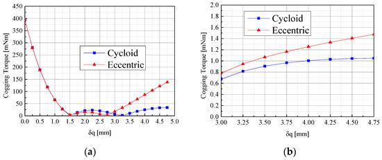
As shown in Figure 9, the 6’th orders are dominant orders for the cogging torque at the given values of δq. Figure 10a,b show the cogging torque of the 6’th and 12’th order for the value of δq. As shown in Figure 10a, the 6’th order of cogging torque for the eccentric curve of the magnet increases sharply after δq = 3.0. For this reason, the 6’th and 12’th orders of cogging torque are the main orders for the cogging torque generation for the eccentric and cycloid models. Compared with the eccentric curve model, the 6’th and 12’th orders of cogging torque for the cycloid model are decreased as the values of δq increased.
Figure 10.
Cogging torque (peak-to-peak value) of the 6’th and 12’th orders for the eccentric and cycloid curve of the magnet: (a) 6’th order cogging torque; (b) 12’th order cogging torque.
4. Validation
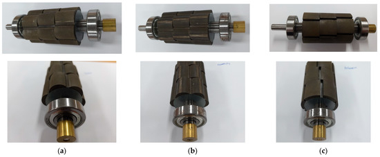
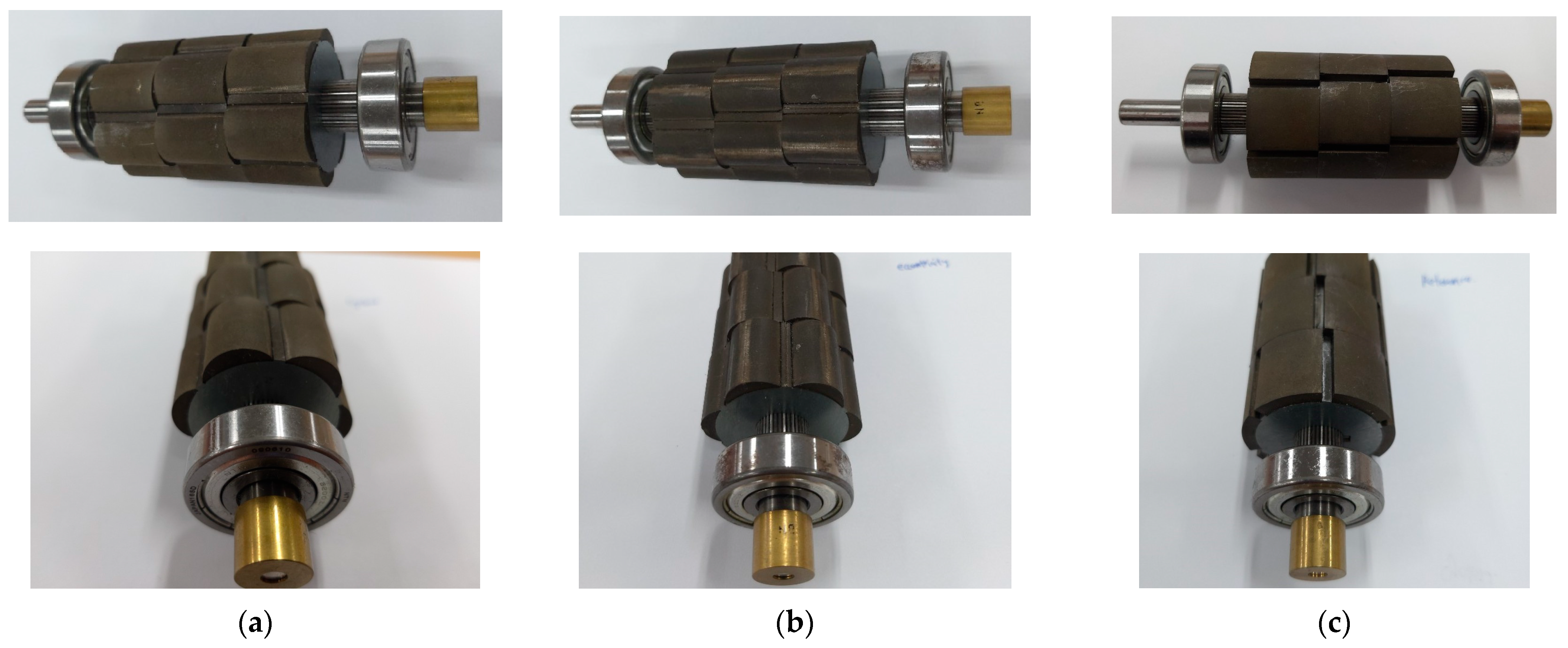
In order to validate the cogging torque reduction for the proposed model, the prototypes are built for the proposed and conventional models as shown in Figure 11. In Figure 11c, the reference model has the value of δq = 4.5, as shown in Figure 11a,b. The reference model was also built to compare the effectiveness for the proposed and conventional models in Figure 11c with δq = 0 for the conventional model.
Figure 11.
Protypes for the proposed and conventional model at δq = 4.5. (a) Cycloid for the proposed model; (b) eccentric for the conventional model; (c) reference model.
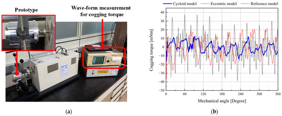
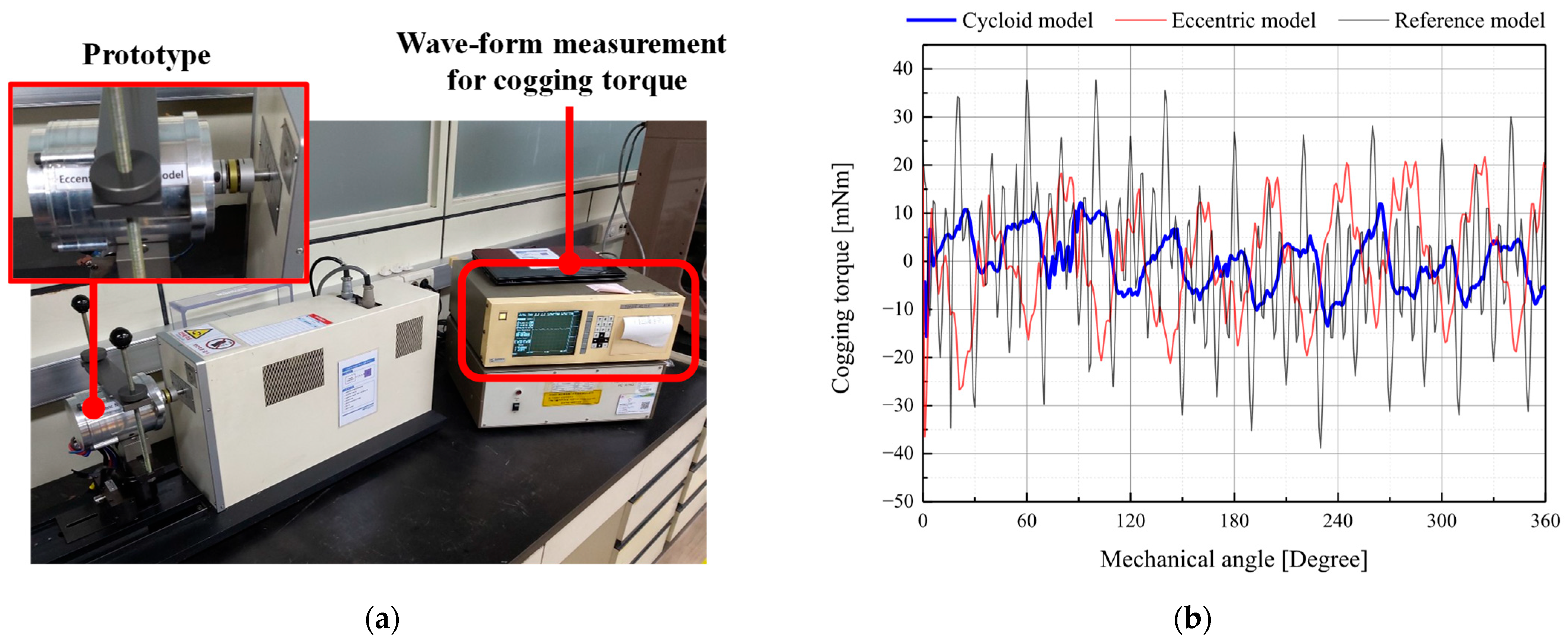
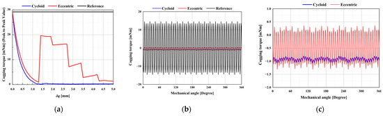
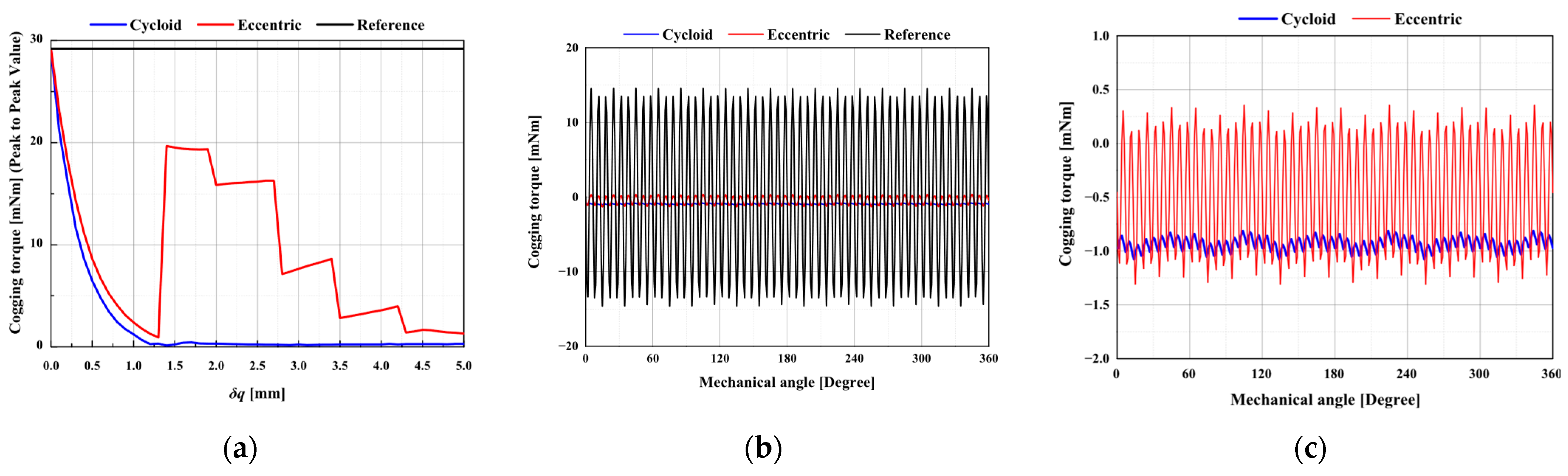
Figure 12a,b show the measurement equipment to measure the waveforms of cogging torque and the measurement results of cogging torque waveforms for the prototypes are shown in Figure 11. Figure 13 shows the analysis results of cogging torque waveforms for the prototypes as shown in Figure 11. Figure 13c shows the expanded cogging torque waveforms for the cycloid and eccentric model shown in Figure 13b.
Figure 12.
Measurement equipment and test results: (a) Measurement equipment; (b) Test results of cogging torque waveforms for the 3 prototypes with a 360 degree mechanical angle.
Figure 13.
FEM results: (a) cogging torque (peak-to-peak value) for the δq; (b) waveforms of cogging torque for the cycloid, eccentric, and reference models for a 360 degree mechanical angle; (c) waveforms of cogging torque for the cycloid and eccentric models for a 360 degree mechanical angle.
Based on the analysis and tests results shown in Figure 12 and Figure 13, the peak-to-peak values of cogging torque for the prototypes in Figure 11 are shown in Table 3. The effectiveness of cogging torque reduction for the proposed model with the cycloid was verified through the results of the analysis and test as shown in Figure 12 and Figure 13 and Table 3.
Table 3.
Cogging torque for the non-skew and 3 step-skew model δq = 4.5.
However, there are considerable differences in the peak-to-peak values of cogging torque between the analysis and test results in Table 3. In this study, the motor used in the EPS system was a high-precision motor, and the EPS system had a strict cogging torque limit, with units of mNm. For this reason, these considerable differences in cogging torque for the analysis and test results are affected by manufacturing deteriorations [6,25,28].
Although there are considerable differences between the analysis and test results, the peak-to-peak values of cogging torque for the proposed model have little variation for the δq from 1.0 to 5.0, as shown in Figure 10a and Figure 13a. For this reason, the proposed model for the non-skew and skew models are verified as the robust model for manufacturing deteriorations compared with the conventional model.
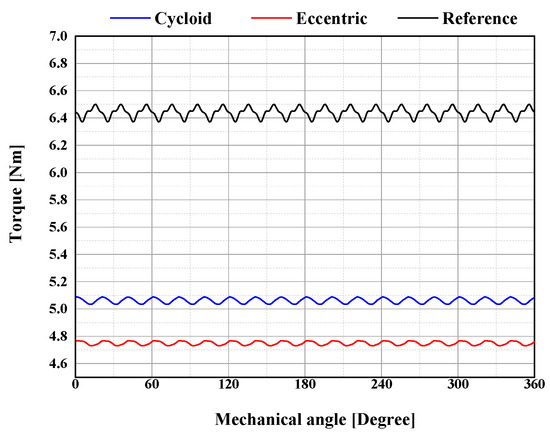
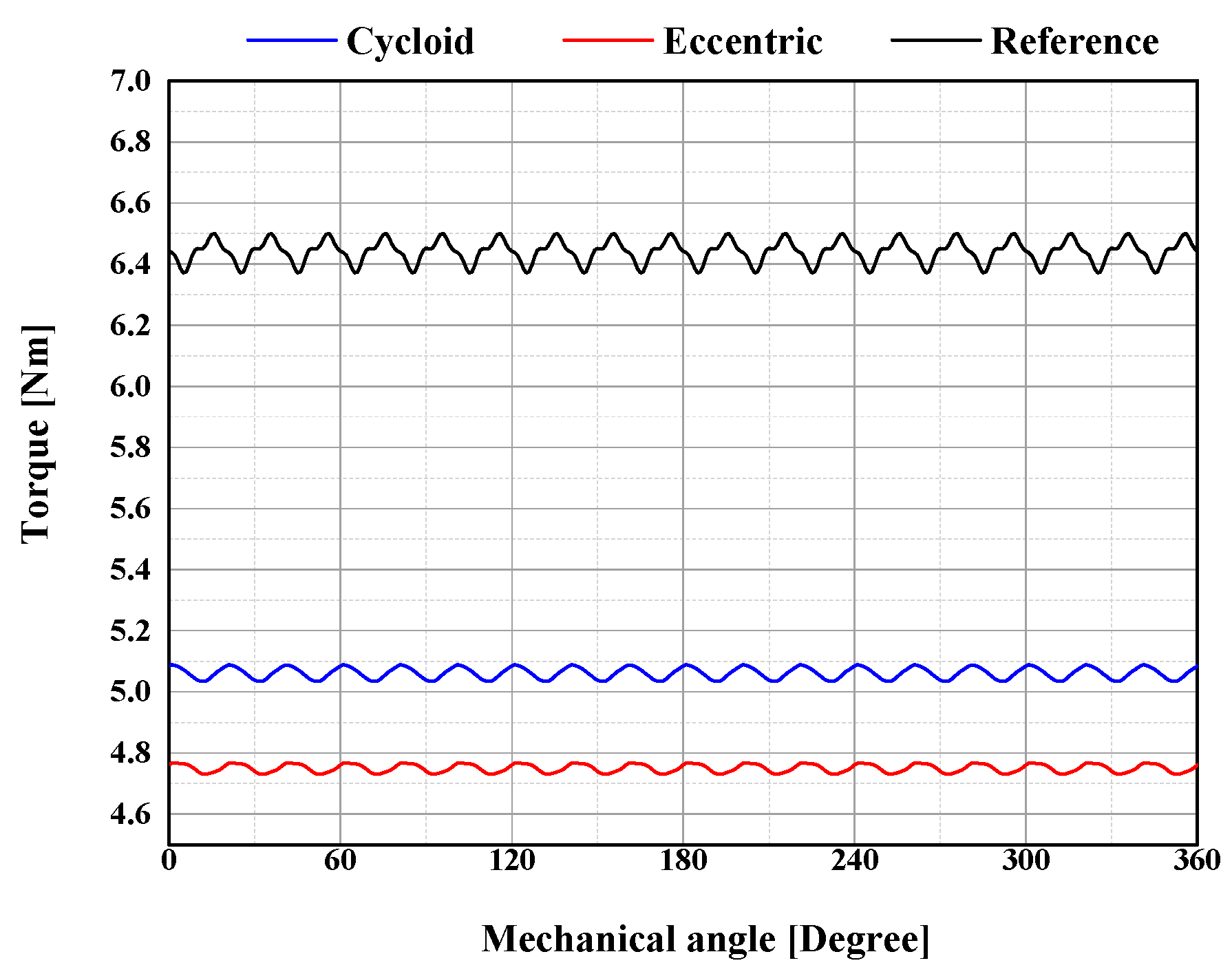
In the case of the load analysis of electromagnetic torque, the waveforms of torque are shown in Figure 14 and Table 4 for the conventional and proposed models. The numerical analysis conditions are conducted with 1500 rpm and 120 Apeak for mechanical 360 degrees rotation. As shown in Figure 14 and Table 4, the average torque for the proposed model is increased by 10% compared with the conventional model. In the case of torque ripple, there are little differences between the conventional and proposed models.
Figure 14.
Wave-forms of torque for the proposed, conventional and reference model.
Table 4.
Waveforms of torque for the 3 step-skew models with δq = 4.5.
5. Conclusions
This study considered cogging torque reduction and robustness design to improve steering feeling and drive stability in EPS systems. This study proposed a design method of magnet shape with a step-skew model to reduce cogging torque. The design strengths of the proposed design method with the cycloid curve of the magnet were verified through analysis and test results and compared with the conventional model.
The cogging torque for the proposed model is reduced by 72% compared with the conventional model in the case of the non-skew model. In the case of the 3 step-skew model, the cogging torque for the proposed model is reduced by 88% compared with the conventional model. Based on the order analysis results for cogging torque wave-form, the 6’th and 12’th orders of cogging torque are the most dominant orders to increase cogging torque in the proposed and conventional models. Compared with the conventional model, the 6’th and 12’th orders of cogging torque in the proposed model decreased sharply as the δq increased. The effectiveness of cogging torque reduction for the proposed model was validated through the test results with the prototypes.
However, it was verified that there were considerable differences in the cogging torque between the analysis and test results due to manufacturing deteriorations. These considerable differences in cogging torque for the analysis and test results are affected by manufacturing deteriorations for the motor in EPS systems with the required lowest cogging torque. In this study, it was also verified that the proposed model shows a robust cogging torque reduction for the manufacturing variations compared with the conventional model.
In the case of the load analysis of electromagnetic torque, a numerical analysis of the waveforms of torque was conducted for the conventional and proposed models. The numerical analysis conditions are conducted with 1500 rpm and 120 Apeak for mechanical 360 degrees rotation. The average torque for the proposed model is increased by 10% compared with the conventional model. For this reason, it is concluded that the proposed model will be a cost-effective candidate solution with a high-torque design compared with the conventional model. In the case of torque ripple, there are little differences between the conventional and proposed models.
The verified results for the proposed model will be extended to meet the required cogging torque variation constraints for the various applications driven by SPMSMs with the robust design model. In future studies, load tests for electromagnetic torque such as torque waveforms will be conducted.
Funding
This work was supported by the Sun Moon University Research Grant of 2023.
Data Availability Statement
The data are contained within the article.
Conflicts of Interest
The author declares no conflicts of interest.
References
- Zou, Y.; Yang, Y.; Zhang, Y. Configuration and parameter design of electrified propulsion systems for three dimensional transportation: A comprehensive review. Green Energy Intell. Transp. 2025. [Google Scholar] [CrossRef] [Scilit]
- Sankhwar, P. Application of Permanent Magnet Synchronous Motor for Electric Vehicle. Indian J. Des. Eng. 2024, 4, 1–6. [Google Scholar] [CrossRef] [Scilit]
- Yang, A.; Zang, Y.; Xu, L.; Li, L.; Tan, D. A systematic review and future development of automotive chassis control technology. Appl. Sci. 2023, 13, 11859. [Google Scholar] [CrossRef] [Scilit]
- Li, Y. Advanced X-by-Wire technologies in design, control and measurement for vehicular electrified chassis. World Electr. Veh. J. 2023, 14, 136. [Google Scholar] [CrossRef] [Scilit]
- EPS System. Available online: https://www.hlmando.com/en/solution/chassis/steering/electric-power/r-eps.do (accessed on 1 August 2025).
- Lee, C.S. Design and Validation of Magnet Shape for SPMSM with Cycloid Curve. Ph.D. Thesis, Hanyang University, Seoul, Republic of Korea, 2017. [Google Scholar]
- Choi, D.; Kim, D.; Han, D.; Kim, W. Design of a slotless structure for minimizing cogging torque and torque ripple in a column type EPS motor for vehicles. IEEE Trans. Magn. 2024, 60, 8700305. [Google Scholar] [CrossRef] [Scilit]
- Lee, Y.; Gil, J.; Kim, W. Velocity control for sideband harmonics compensation in permanent magnet synchronous motors with low switching frequency inverter. IEEE Trans. Ind. Electron. 2021, 68, 3434–3444. [Google Scholar] [CrossRef] [Scilit]
- Jung, W.-S.; Lee, H.-K.; Lee, Y.-K.; Kim, S.-M.; Lee, J.-I.; Choi, J.-Y. Analysis and comparison of permanent magnet synchronous motors according to rotor type under the same design specifications. Energies 2023, 16, 1306. [Google Scholar] [CrossRef] [Scilit]
- Wanjiku, J.; Khan, M.A.; Barendse, P.S.; Pilay, P. Influence of slot openings and tooth profile on cogging torque in axial-flux pm machines. IEEE Trans. Ind. Electron. 2015, 62, 7578–7589. [Google Scholar] [CrossRef] [Scilit]
- Hwang, M.; Lee, H.; Cha, H. Analysis of torque ripple and cogging torque reduction in electric vehicle traction platform applying rotor notched design. Energies 2018, 11, 3053. [Google Scholar] [CrossRef] [Scilit]
- Qian, H.; Guo, H.; Wu, Z.; Ding, X. Analytical solution for cogging torque in surface-mounted permanent-magnet motors with magnet imperfections and rotor eccentricity. IEEE Trans. Magn. 2014, 50, 8201615. [Google Scholar] [CrossRef] [Scilit]
- Zhou, Y.; Li, H.; Meng, G.; Zhou, S.; Cao, Q. Analytical calculation of magnetic field and cogging torque in surface-mounted permanent-magnet machines accounting for any eccentric rotor shape. IEEE Trans. Ind. Electron. 2015, 62, 3438–3447. [Google Scholar] [CrossRef] [Scilit]
- Zhang, G.; Hou, P. Optimization Design of Cogging Torque for Electric Power Steering Motors. Machines 2024, 12, 517. [Google Scholar] [CrossRef] [Scilit]
- Lee, C.-S.; Jung, K.-T.; Hong, J.-P.; Kim, H.-J.; Kim, Y.-K. Design of brushless permanent machine with skewed stator for electrical power steering system. J. Korean Magn. Soc. 2015, 25, 189–197. [Google Scholar] [CrossRef] [Scilit]
- Jiang, J.W.; Bilgin, B.; Yang, Y.; Sathyan, A.; Dadkhah, H.; Emadi, A. Rotor skew pattern design and optimization for cogging torque reduction. IET Electr. Syst. Transp. 2015, 6, 126–135. [Google Scholar] [CrossRef] [Scilit]
- Said, S.M.; Nur, T.; Herlina, H. The Application of Magnet Structures to Reduce the Cogging Torque Associated with Fractional Slot Number in Permanent Magnet Generators. Energies 2024, 17, 2505. [Google Scholar] [CrossRef] [Scilit]
- Ying, H.; Zhang, Z.; Gong, J.; Huang, S.; Ding, X. Application for Step-skewing of Rotor of IPM Motors Used in EV. World Electr. Veh. J. 2010, 4, 532–536. [Google Scholar] [CrossRef] [Scilit]
- Ozcelik, N.G.; Sen, I.; Ergene, L.T. A Case Study: An Approach to Decrease Voltage Distortion and Enhance Field Weakening Capability in BMW i3 Traction Motor. IEEE Access 2024, 12, 145881–145892. [Google Scholar] [CrossRef] [Scilit]
- Blum, J.; Merwerth, J.; Herzog, H.G. Investigation of the Segment Order in Step-Skewed Synchronous Machines on Noise and Vibration. In Proceedings of the 2014 4th International Electric Drives Production Conference (EDPC), Nuremberg, Germany, 30 September–1 October 2014; pp. 1–6. [Google Scholar]
- Wu, T.; Schwarzer, D.; Neuwald, T.; Wüst, P.; Maczionsek, D.; Seibicke, F.; Rauch, H.; Schäfer, U. Investigation and comparison of permanent magnet rotors produced by different additive manufacturing methods. Elektrotech. Inftech. 2024, 141, 155–163. [Google Scholar] [CrossRef] [Scilit]
- Frank, T.J.; Troben, O.A. The cycloid permanent magnetic gear. IEEE Trans. Ind. Appl. 2008, 244, 1659–1664. [Google Scholar] [CrossRef] [Scilit]
- Choi, T.H.; Kim, M.S.; Jung, S.Y. Design of gerotor using cycloid and circular-arc curves. Trans. Korean Soc. Mech. Eng. A 2011, 35, 241–250. [Google Scholar] [CrossRef] [Scilit]
- Shin, J.H.; Kown, S.M. On the lobe profile design in a cycloid reducer using instant velocity center. Mech. Mach. Theory 2006, 41, 596–616. [Google Scholar] [CrossRef] [Scilit]
- Lee, C.S.; Lim, M.S.; Park, H.J. Magnet shape design and verification for SPMSM of EPS System Using Cycloid Curve. IEEE Access 2019, 7, 137207–137216. [Google Scholar] [CrossRef] [Scilit]
- Jang, J.; Cho, S.-G.; Lee, S.-J.; Kim, K.-S.; Kim, J.-M.; Hong, J.-P.; Lee, T.H. Reliability-based robust design optimization with kernel density estimation for electric power steering motor considering manufacturing uncertainties. IEEE Trans. Magn. 2015, 51, 8001904. [Google Scholar] [CrossRef] [Scilit]
- Wang, C.; Shen, J.; Luk, P.; Fei, W.; Jin, M.; Masmoudi, A. Design issues of an IPM motor for EPS. COMPEL Int. J. Comput. Math. Electr. Electron. Eng. 2011, 31, 71–87. [Google Scholar]
- Lee, C.S.; Kim, H.J. Harmonic Order Analysis of Cogging Torque for Interior Permanent Magnet Synchronous Motor Considering Manufacturing Disturbances. Energies 2022, 15, 2428. [Google Scholar] [CrossRef] [Scilit]
- Kim, J.M.; Yoon, M.H.; Hong, J.P.; Kim, S.I. Analysis of cogging torque caused by manufacturing tolerances of surface-mounted permanent magnet synchronous motor for electric power steering. IEEE Trans. Electr. Power Appl. 2016, 10, 691–696. [Google Scholar] [CrossRef] [Scilit]
- Jun, C.S.; Kwon, B.I.; Kwon, O.B. Tolerance Sensitivity Analysis and Robust Optimal Design Method of a Surface-Mounted Permanent Magnet Motor by Using a Hybrid Response Surface Method Considering Manufacturing Tolerances. Energies 2018, 11, 1159. [Google Scholar] [CrossRef] [Scilit]
- Ma, B.; Lei, G.; Zhu, J.G.; Gou, Y.G.; Liu, C.C. Application-Oriented Robust Design Optimization Method for Batch Production of Permanent-Magnet Motors. IEEE Trans. Ind. Electron. 2017, 65, 1728–1739. [Google Scholar] [CrossRef] [Scilit]


Disclaimer/Publisher’s Note: The statements, opinions and data contained in all publications are solely those of the individual author(s) and contributor(s) and not of MDPI and/or the editor(s). MDPI and/or the editor(s) disclaim responsibility for any injury to people or property resulting from any ideas, methods, instructions or products referred to in the content. |
© 2025 by the author. Licensee MDPI, Basel, Switzerland. This article is an open access article distributed under the terms and conditions of the Creative Commons Attribution (CC BY) license (https://creativecommons.org/licenses/by/4.0/).