


Abstract
Fiber bridging and matrix fracture jointly govern tensile cracking in engineered cementitious composites (ECC), and the modeling scale depends on the response of interest. This structured narrative review uses topic searches and citation tracking to compare macroscale, Meso-II and Meso-I models. The comparison covers numerical method, spatial dimension, fiber representation, material variability, crack prediction and experimental evaluation. At the macroscale, a tensile damage model predicted a static peak load of 67.5 kN and a corresponding midspan deflection of 20.4 mm for a bridge deck link slab, compared with 67.1 kN and 21.1 mm measured. At Meso-II, a stochastic cohesive crack model linked collective bridging to multiple cracking and, with variable sectional fiber content, predicted a mean ultimate tensile strain of 1.78%, compared with 1.86% measured. At Meso-I, a three-dimensional finite element model resolved load transfer by individual fibers and predicted a mean crack width of 128 μm in direct tension, compared with 129 ± 12 μm measured. These comparisons identify the strengths and limitations of each scale, guide model selection for structural analysis, crack control and fiber–matrix interface design and establish priorities for further research.
1. Introduction
Engineered cementitious composites (ECC) combine high tensile ductility and toughness with a characteristic multiple-cracking failure mode and have attracted considerable interest in structural engineering [1,2,3]. Under uniaxial tension, ECC can sustain increasing stress after numerous fine cracks form. In mixtures designed for crack control, crack widths generally remain below 100 μm during strain hardening [1,4,5]. This combination of deformation capacity and crack control supports structural applications and can improve long-term performance by limiting the ingress of water and other substances through cracks in the matrix [4,5,6].
ECC belongs to the broader class of strain-hardening cementitious composites (SHCC) [1,7]. We use ECC as a general term in this review and retain the names used in individual studies, including SHCC, ultra-high-toughness cementitious composites (UHTCC) and high-strength, high-ductility concrete (HSHDC). Micromechanical design of ECC matches matrix fracture resistance to fiber-bridging capacity [8,9,10,11,12]. Fiber type, volume fraction, geometry and fiber–matrix interface properties jointly govern this balance [10,11,12,13,14].
The design theory of ECC can relate composite performance to its composition and material properties. In 2002, Victor Li [15] proposed the concept of Integrated Structures and Materials Design (ISMD), linking the mesoscale of materials with the macroscale of structures. In this concept, structural mechanics relates material properties, structural form, and structural performance, whereas micromechanics relates material microstructure, production technology, and material properties. Material properties provide the connection between these two levels; for ECC, the crack bridging stress–crack width (σ–δ) relation and the resulting composite tensile stress–strain (σ–ε) relation are central to this connection.
Figure 1 traces the transfer of constitutive information from the fiber–matrix interface to the ECC member [16]. At the microscale, fiber, matrix and interface properties determine the single-fiber pullout load–displacement relation during debonding and subsequent frictional slip. Single-fiber pullout tests provide data for parameter calibration and response checks [17,18,19,20]. At Meso-I, the number, embedment lengths and orientations of the fibers crossing a crack determine their individual force contributions. Summing these contributions and dividing by the crack area gives the bridging traction as a function of crack opening and slip. The tensile branch can be evaluated in a single-crack tension test [21]. At Meso-II, the bridging law and the statistics of matrix flaws and cracking thresholds govern the formation and evolution of multiple cracks. The model predicts crack number, spacing and widths and combines the matrix strain between cracks with their opening and sliding displacements to obtain an effective composite stress–strain law. Crack measurements and the overall stress–strain curve from a composite tension test evaluate these two outputs. At the macroscale, the effective law, member geometry and loading determine the predicted load response, deformation and progression of failure, which can be assessed in structural tests [16].
Figure 1.
Multiscale modeling framework and cross-scale information transfer for tensile cracking in ECC [15,16].
Experiments characterize the tensile response of ECC for a given mixture and loading condition and can resolve distinct aspects of crack development. Digital image correlation provides full-field measurements of surface crack openings [21], X-ray tomography resolves cracks within the imaged volume [22,23], and acoustic emission records the timing of damage initiation and progression [24,25]. Specimen variability, testing conditions and cost limit systematic variation in one mesoscale parameter at a time and make interactions among parameters difficult to quantify [19,20,21,26,27,28,29]. Starting from parameters calibrated in single-fiber pullout tests, numerical simulations can vary one parameter at a time, such as interfacial frictional bond strength, and trace its effect on pullout force, bridging stress, crack-width distribution and tensile strain capacity. Varying parameters in combination reveals their interactions. Comparison with stress–strain curves and crack measurements from independent tension tests evaluates how the model represents load transfer and cracking and informs interface design and control of tensile performance.
Previous reviews have examined experimental characterization, material design and numerical modeling of the tensile behavior of ECC from different perspectives. Yoo and Banthia [14] reviewed the influence of matrix proportions, fiber type and aspect ratio on the ductility of strain-hardening cementitious composites with tensile strain capacities above 4%. Yu et al. [27] examined how fiber type, specimen size and geometry, and strain rate affect direct tension results for ECC. Ding et al. [30] addressed joint design for strength and ductility, material properties and structural applications of high-strength, high-ductility concrete (HSHDC). Building on these studies and the review of pullout, bridging and tensile models by Ribeiro et al. [31], we classify numerical models of tensile cracking into macroscale, Meso-II and Meso-I formulations. Effective constitutive laws predict member capacity and deformation, collective bridging laws relate crack formation to spacing and width, and individual fiber models resolve how pullout and rupture influence cracking. We compare spatial dimension, crack discretization and material variability, and use test evidence to assess the suitability and limitations of each approach for structural analysis, crack control and fiber–matrix interface design.
2. Review Methodology and Model Classification
We used a structured narrative review to identify numerical studies of tensile cracking in ECC, SHCC, UHTCC and HSHDC. We combined material names with tensile cracking, multiple cracking and fiber bridging, and with numerical methods including lattice models, random fields and phase fields. We supplemented the searches by tracing references and subsequent citations. Publisher sites and institutional repositories provided original publications, and Crossref and OpenAlex supported bibliographic checks and citation tracking. We screened titles and abstracts and examined available full texts for constitutive assumptions, discretization and experimental validation. We included numerical studies investigating tensile cracking behavior, including those evaluating tensile constitutive models under different loading conditions, such as direct tension, flexural loading, and cyclic loading. Experimental studies supplied calibration and comparison data. Following the multiscale approaches of Li and Kabele [15,16], we classified the included models as macroscale, Meso-II or Meso-I and recorded their spatial dimension, fiber representation, treatment of material variability, representation of crack kinematics, input parameters, loading conditions and predicted quantities.
The finest interaction retained during the solution defines the scale. A macroscale model updates the material-point stress from the strain increment and loading history through an effective stress–strain law. A Meso-II model uses a single-crack traction–separation law to calculate the collective fiber traction per unit crack area from opening or tangential slip. A Meso-I model evaluates load transfer between each fiber and the matrix through an interface relation, such as a bond–slip law and calculates each fiber’s contribution to bridging.
3. Comparative Review of Models
This section starts with macroscale laws for member response, then considers Meso-II models of multiple cracking through collective bridging and Meso-I models of individual fiber force transfer. The applications, advantages and limitations of these formulations are systematically summarized. Comparisons with measured quantities provide a basis for selecting a model for a particular objective and dataset.
3.1. Macroscale Numerical Simulation of ECC
At the macroscale, an equivalent stress–strain law supplies the material response at each integration point. Its parameters can be fitted to coupon tests, derived by averaging a Meso-II response, or identified using both sources. Member analyses then predict internal forces, displacements and load capacity under the loading paths covered by that law.
The development of macroscale ECC simulation is closely related to advances in constitutive modeling. Reviews summarize the tensile behavior of ECC under different loading regimes [27,30], and dedicated cyclic formulations address unloading and reloading [32]. Rate effects have been investigated experimentally and through dynamic micromechanical modeling [33,34]. The models discussed below illustrate the progression from uniaxial idealizations to multidimensional formulations and from monotonic to cyclic and rate-dependent responses.
Based on direct tension test results, M. Maalej and V.C. Li [35] simplified the uniaxial tensile stress–strain curve of ECC into a bilinear constitutive model, which was used to derive the formula for the flexural capacity of ECC beams. Boshoff and van Zijl [36] incorporated tensile hardening and softening into a regularized continuum damage model and evaluated the model in three-point bending and shear. The model underestimated Iosipescu shear strength by approximately 30%, showing the limit of the tensile calibration under shear. Subsequently, considering that structural design requires a certain simplicity, the JSCE recommendations [37] and the RILEM state-of-the-art report [38] discuss ideal elastoplastic approximations of the tensile response. Schematic curves of the three aforementioned constitutive models are presented in Figure 2.
Figure 2.
Idealized tensile constitutive relations for ECC [35,36,37,38]: (a) bilinear tensile strain-hardening constitutive model; (b) trilinear tensile constitutive model with softening; (c) ideal elastoplastic tensile constitutive model. σ and ε denote tensile stress and strain.
The above ECC constitutive relations under one-dimensional stress states can only be used for the analysis of simple stress states, such as direct tension and pure bending, and cannot be applied to analysis of multidimensional stress states. Based on plasticity theory, Kabele [39,40] proposed a yield-surface rule for ECC under the two-dimensional stress state, arguing that when the maximum principal stress reaches the first-crack strength, cracks form perpendicular to the maximum principal stress direction and gradually develop into multiple cracking; this behavior is termed smeared plastic behavior. The yield surface under the two-dimensional stress state can be defined by the Rankine yield equation as:
where F is the yield function (F = 0 on the yield surface), σfc is the first-crack tensile strength, and σij* is the stress shifted by the back stress αij, as defined in Equation (2). The indices i and j denote the in-plane x and y directions. σij is the Cauchy stress tensor, for which σxy = σyx. The maximum principal value of the shifted stress combines the normal and shear components.
In Equation (3), d denotes an increment, αij is the back stress tensor controlling translation of the yield surface, εijc is the inelastic cracking-strain tensor, and h is the kinematic-hardening modulus relating their increments. The modulus is calibrated from the post-cracking uniaxial response [39].
Beyond plane-stress formulations, Wu et al. [41] developed a three-dimensional plasticity-based model for UHTCC, a strain-hardening cementitious composite in the ECC family. Calibrated for a 2% PVA-fiber content using uniaxial, biaxial and triaxial confinement data, the model describes pressure-dependent strength and distinct tensile and compressive stress–strain responses. The model captures tensile strain hardening followed by post-peak softening, as well as the increase in axial compressive strength with increasing lateral confinement. Figure 3 illustrates its macroscopic response features.
Figure 3.
Three-dimensional constitutive model for UHTCC [41]: (a) conventional triaxial compression; (b) tensile hardening and softening; (c) confinement-dependent compressive response. σ1, σ2 and σ3 denote principal stresses; sa = |σ1| is the axial compressive stress magnitude, and pc = |σ2| = |σ3| is the lateral confining pressure. σt and εt denote tensile stress and strain, and |ε1| denotes the axial compressive strain magnitude.
To conduct structural analysis under seismic action, Han et al. [42] proposed an ECC cyclic model to capture unloading and reloading. Gencturk and Elnashai [43] subsequently developed a cyclic constitutive formulation with distinct tensile and compressive envelopes, stiffness degradation and residual strains. Their model was calibrated mainly against the experiments of Kesner and Billington [44] and independently assessed using the results of Fukuyama et al. [45]. It was implemented for structural component analysis under cyclic loading. Zhu et al. [46] used a macroscale tensile damage law for ECC under high-cycle loading in a cycle-driven finite element model of a reinforced bridge link slab. The calculation tracks damage in ECC and reinforcement separately. As cycles accumulate, residual plastic strain shifts the start of tensile reloading and stiffness degradation reduces its slope. The reloading branch meets the static envelope at a point determined by the damage state (Figure 4c). Under static bending, the predicted peak load was 67.5 kN at a midspan deflection of 20.4 mm, compared with 67.1 kN at 21.1 mm in the test. For the second stage fatigue loading of link slab LS2, the calculated and measured fatigue lives are 63,360 and 45,317 cycles, respectively. Figure 4 shows the constitutive relationships described above.
Figure 4.
Schematic constitutive responses of ECC under cyclic loading and high-cycle fatigue: (a) tensile–compressive envelopes and unloading–reloading responses of ECC [42]; (b) reversed cyclic tension–compression response of ECC [43]; (c) schematic tensile constitutive responses of ECC after different levels of fatigue damage. σ and ε denote stress and strain [46]. In (a), A, B and C mark tensile first cracking (εt0, σt0), the tensile peak (εtp, σtp) and the compressive peak (εcp, σcp), respectively; εr,t and εr,c denote residual strains. In (b), T and C mark the attained tensile and compressive extremes (εtmax, σtmax) and (εcmin, σcmin), respectively; εtul and εcul are unloading zero-stress intercepts.
To account for strain rate effects in high-strength, high-ductility concrete (HSHDC), Ranade [47] used direct tension tests to relate tensile strength to strain rate through a dynamic increase factor (DIF). Two power laws meet at 10 s−1, giving two linear branches on logarithmic axes (Figure 5a). Companion direct tension measurements for this material are reported by Ranade et al. [48]. Wu et al. [41] developed a macroscale dynamic plasticity and damage model for UHTCC that accounts for the combined effects of strain rate on strength, deformation and damage evolution. The model describes dynamic tension and compression separately. It represents tensile strain hardening, softening and damage evolution, as well as the rate dependence of tensile strength and strain at peak tensile stress (Figure 5b). The authors implemented the model through a user material interface in LS-DYNA and assessed it using single-element simulations and high-velocity penetration and contact explosion tests. They reported overall agreement between the calculations and measurements. Extending the description beyond strength enhancement alone, the model accounts for rate effects on tensile deformation capacity and damage evolution in macroscale analyses of ECC-type materials under dynamic loading.
Figure 5.
Schematic representation of strain rate effects on the tensile behavior of high-ductility cementitious composites: (a) tensile dynamic increase factor (DIF) versus strain rate for HSHDC [47]; (b) Rate-dependent tensile stress–strain response of UHTCC [41].
Macroscale constitutive models can be used to calculate member forces and deformations. Distributed cracking enters through the average stress–strain relation, so agreement with a measured load–deflection curve does not determine individual crack locations or widths. One extension represents the cumulative deformation of fine cracks by an equivalent strain and localized fracture by a separate field.
Y. Yu et al. [49] coupled a pseudo-plastic constitutive law to a fracture phase field to describe the transition from strain hardening to localized fracture in ECC. During hardening, pseudo-plastic strain represents the cumulative opening of distributed fine cracks. A von Mises flow rule with linear isotropic hardening describes the continued increase in tensile stress after first cracking. A stress-weighted degradation law then updates fracture toughness according to the history of multiaxial stress. Evolution of the phase field describes the formation and propagation of the dominant crack. The authors applied the model to four-point bending of PVA-ECC beams with offset notches of different depths to examine crack growth under combined opening and in-plane shear.
Macroscale models can also account for environmental changes in material properties to analyze how ECC members respond to fire or freeze–thaw exposure. Tang et al. [50] represented the loss of stiffness and strength of ultra-lightweight ECC during fire exposure by a temperature-dependent macroscale constitutive law. A thermomechanical finite element analysis predicted midspan deflection under standard fire exposure. For the 160 mm thick EC-60-100-3 composite slab, the predicted deflection at 60 min was approximately 23.2 mm, about 7% below the measured value of approximately 24.9 mm.
Han et al. [51] treated PE-ECC as a continuum. A trilinear tensile law represented the elastic, strain-hardening and post-peak softening stages, and a damage plasticity law described compression. The authors first calculated the transient temperature field during freezing and thawing. They then adjusted the constitutive model parameters of PE-ECC as a function of the minimum cycle temperature and the number of cycles to simulate four-point bending of reinforced beams after exposure. After 200 cycles, the calculated and measured ultimate loads were 56.6 and 54.0 kN, respectively. The corresponding ultimate deflections were 12.9 and 12.3 mm. The model overpredicted load by 4.8% and deflection by 4.9%.
3.2. Meso-II Scale Numerical Simulation of ECC
Meso-II models describe the collective force transfer of crossing fibers through a single-crack bridging stress–opening relation. This relation can be measured in single-crack tests or calculated from single-fiber load–slip laws and orientation statistics. Analytical models use it to estimate crack spacing and ultimate tensile strain. Volume averaging includes the deformation associated with crack opening in the composite strain. Lattice and finite element models can assign the relation to crack-crossing links or to cohesive interfaces [52,53].
Kanda et al. [54] used a bilinear approximation to the tensile stress–strain curve. The first branch has the composite elastic modulus as its slope and ends at the steady-state cracking stress, used to approximate first cracking. The second branch connects this point to the peak tensile stress, determined by the maximum bridging stress. Assuming comparable openings at peak load and neglecting elastic extension between cracks, ultimate tensile strain is approximated by the opening at peak bridging stress divided by the final mean crack spacing.
To calculate final spacing, Kanda et al. [54] accounted for the dependence of cracking stress on matrix flaw size. Smaller flaws require higher stresses to grow. Where the required stress exceeds the maximum bridging stress, a flaw remains inactive even at peak load. Fewer cracks then form, so the final mean spacing exceeds the saturated spacing (Figure 6). The model estimates the fraction of inactive flaws from their size distribution. For the four-week-old composite with 1.0 vol% PE fibers, the calculated saturated spacing was 4.12 mm. Allowing for inactive flaws gave 6.98 mm, approximately 4.4% below the measured mean of 7.30 mm for two specimens.
Figure 6.
Link between crack bridging and the ultimate tensile state [54]: (a) stress–COD point corresponding to the ultimate state; (b) composite surface at the ultimate state; (c) stress–strain relation. σpeak is the peak bridging stress, δpeak its associated opening, xd the final crack spacing, and εcu the ultimate average tensile strain.
Lu and Leung [55] developed an axial stress transfer model of successive crack formation. It accounts for strength variations along the matrix, the growth of bridging stress with crack opening, and fiber rupture. After a crack forms, the crossing fibers transfer load back to the matrix on either side through the interface. A new crack forms where the recovered stress reaches the local matrix cracking strength. This calculation yields nonuniform spacing along the specimen and relates the openings of successive cracks to tensile deformation.
Kabele’s RVE-II model [16] adopts an equivalent continuum description [56] and relates volume-averaged stress to volume-averaged strain. The two orthogonal crack families in Figure 7a illustrate multiple cracking in two dimensions. The first family forms normal to the maximum principal tensile stress at first cracking. The second forms only if the orthogonal direction also satisfies the initiation criterion. The bridging law relates normal opening and tangential slip to the traction carried by fibers across the crack (Figure 7b) [16]. Volume averaging combines the elastic strain between cracks with the deformation of each active crack family to obtain the total strain in Figure 7c. Each family’s contribution depends on crack count, orientation, opening and slip. At the same mean opening, a higher crack density produces a greater accumulated tensile strain [56]. Updating crack count and deformation during loading gives the effective stress–strain law in the multiple-cracking regime [16].
Figure 7.
Kabele’s RVE-II formulation [16,56]: (a) representative volume element with orthogonal crack sets; (b) opening and sliding of a fiber-bridged crack; (c) strain decomposition of the representative volume element. δn and δs denote normal opening and tangential sliding; t and denote the traction vector and its constitutive relation. The overall strain combines the average elastic strain and the contributions εijcr,1 and εijcr,2 of the active crack families; i and j are tensor-component indices.
Among these subsequent numerical strategies, the lattice approach, originally proposed for elasticity by Hrennikoff [57] and later adapted for concrete fracture simulations by Schlangen and van Mier [58], was adopted by Spagnoli [59] to analyze ECC under tension using an equilateral triangular lattice model, which substitutes the continuum multiphase model with discrete truss elements. This equilateral triangular lattice model consists of hinged trusses assembled from hexagonal unit cells. Spagnoli’s work established a transformation scheme to convert the continuum plane-stress field into the truss stress field of the lattice model and treated the ECC tensile stress–strain constitutive response as a combination of matrix deformation, matrix cracking, and fiber-bridging contributions. For the homogeneous regular triangular pin-jointed lattice, the equivalent Poisson ratio is fixed at 1/3 [59]. Figure 8 distinguishes crack-face traction superposition from the addition of elastic and cracking strains.
Figure 8.
Spagnoli’s lattice formulation [59]: (a) triangular lattice model with zero-stiffness void links; (b) superposition of matrix and fiber-bridging tractions; (c) construction procedure for the truss element constitutive law. w is crack opening; t = tm + tf combines matrix and fiber tractions. σ, E and Gf denote stress, Young’s modulus and fracture energy; overbars identify mapped truss quantities. is total truss strain, = w/l is cracking strain, and l is truss length.
The superimposed ECC stress–strain constitutive model is linear before first cracking and thereafter a piecewise linear post-cracking curve with a softening branch. This constitutive curve was programmed into a UMAT subroutine to simulate the direct tension behavior of the equilateral triangular lattice model in ABAQUS.
To account for material scatter, Spagnoli assigned different material constitutive properties to lattice elements; using the Monte Carlo method, void lattices of different sizes and positions were randomly generated in the matrix, and the stiffness of the void-lattice truss elements was set to zero to simulate the void defects of the matrix. Spagnoli used this lattice model to predict the ECC stress–strain curve under direct tension and characterized the distribution of multiple cracking according to the distribution of damaged truss elements.
Irregular lattices have also been used to describe tensile cracking. Mustafa et al. [60] distributed nodes randomly within cubic voxels and connected them by Delaunay triangulation to form a three-dimensional beam lattice. Each link followed a three-stage effective SHCC stress–strain law. For a 100 × 100 × 200 mm prism in uniaxial tension, a 10 mm voxel size limited the formation of closely spaced cracks and the accumulated extension. A separate comparison concerned a composite PVA-SHCC concrete beam with a smooth interface in four-point bending. At a deflection of 3.8 mm, the calculated and measured maximum surface crack widths in the SHCC layer were approximately 0.16 and 0.13 mm.
Kabele [61] represented the cracking strength σc by a Gaussian random field with an isotropic squared exponential spatial autocorrelation function. The correlation lengths dx and dy were both 10 mm, with correlation almost vanishing at a separation of 2.5 times the correlation length. After cracking, the bridging relation starts at σpc, hardens quadratically to σmb at δmb, and then follows a bilinear softening branch through (δ1, σ1) to (δ0, 0). The local Young’s modulus E, bridging strength σmb and softening-branch stress σ1 are fully correlated with σc at each material point, while the crack opening parameters are deterministic. This couples the local matrix and bridging properties to the same spatially varying strength field.
In Kabele’s work, spatial random fields were generated using the FReET [62] program and then incorporated into an ATENA finite element model [61]. Within this modeling framework, individual cracks were formulated using a crack band approach [63] with a hardening–softening cohesive law. The key characteristics of the model are presented in Figure 9. Measurements of flaw sizes and fiber distribution in PVA-ECC provide a basis for assessing these spatial assumptions [64].
Figure 9.
Kabele’s stochastic finite element model [61]: (a) spatial autocorrelation function of the material random field; (b) fiber-bridging stress–crack opening relationship; (c) stochastic finite element model of the direct tension specimen. ρ is the correlation coefficient, r the separation distance, and d the correlation length (dx = dy = 10 mm). σpc is the initial post-cracking bridging stress; (δmb, σmb) and (δ1, σ1) denote the peak and softening kink, respectively; δ0 is the opening at zero traction. u denotes applied end displacement.
Kabele’s stochastic finite element model [61] is a Meso-II formulation in which spatial variations in matrix cracking strength and fiber-bridging properties affect tensile response and crack pattern. A spatially correlated random field represents continuous variation between neighboring positions. Four limitations follow.
- (1)
- Kabele assumed a Gaussian distribution of local matrix cracking strength. When initiation is governed by the most critical flaw in the tensile region, a weakest-link Weibull distribution is appropriate for strength. Under uniform tension, a larger stressed volume is more likely to contain a critical flaw and has a lower characteristic strength. The scale parameter should therefore be reported with its reference tensile volume and transformed using the effective stressed volume when applied to specimens of different sizes. Each local strength in a Gaussian field can be replaced by the Weibull strength at the same percentile. The resulting strength distribution and the correlation between strengths at different separations should both be checked against their targets.
- (2)
- Mixing and casting can influence both fiber placement and matrix flaws, producing some statistical dependence. Kabele additionally assumed that the peak bridging stress and the stress at the softening kink are proportional to the local matrix cracking strength, with fixed corresponding openings. Bridging also depends on the number, orientation and embedment of crossing fibers. Fiber-rich and fiber-poor regions can therefore show different peak tractions and softening even at similar matrix strengths. A fixed proportion restricts the variation available for crack growth. Paired measurements of cracking strength and bridging at the same positions would test this assumption.
- (3)
- Kabele used a spatially correlated Gaussian strength field with a 10 mm correlation length in both in-plane directions and qualitatively reproduced the influence of specimen width on tensile strength and strain capacity [61]. Correlation length sets the spatial extent of weak regions. The original study did not vary it to test the persistence of the width effect. Directional correlation lengths should be estimated from spatial measurements and their influence examined at fixed element size.
- (4)
- The crack band formulation represents the formation and evolution of multiple cracks. Its local straight crack idealization limits the description of crack deflections and the resulting tortuous paths in ECC.
Huang and Zhang [65] developed a stochastic cohesive crack model in ABAQUS using the extended finite element method (XFEM). Building on the enrichment of Belytschko and Black [66] and its extension to cohesive cracks by Moës and Belytschko [67], the model activates a cohesive crack at an element center when the local criterion is satisfied. The quadrilaterals are arranged in an axial strip. Each element admits one crack perpendicular to the loading axis and spanning the section. The cohesive law superposes matrix and fiber-bridging contributions and is approximated by four linear segments (Figure 10).
Figure 10.
Huang and Zhang’s XFEM model [65]: (a) stochastic characterization of matrix flaws and fiber distribution; (b) normal cohesive constitutive law for cracks; (c) extended finite element model with cracks embedded within elements. tn and δn denote normal traction and opening, related by . The law comprises a plateau at σck up to δck, a peak (δpb, σpb), a softening kink (δnf, σnf), and zero traction at δu.
Huang and Zhang [65] sampled initial matrix flaw sizes from a Weibull distribution and used fracture mechanics to obtain the cracking stress. The fiber volume fraction at each section followed a Gaussian distribution centered on the nominal content. In the direct tension simulation of PVA-ECC, a uniform fiber distribution gave a tensile strain capacity of 3.20%. Allowing sectional fiber content to vary reduced the predicted mean to 1.78%, close to the measured 1.86%.
3.3. Meso-I Scale Numerical Simulation of ECC
Meso-I models evaluate load transfer by each crossing fiber from its properties, embedment length and interfacial law. Figure 11 distinguishes three force–displacement histories. Hydrophobic PE fibers bond weakly to the cementitious matrix, so complete debonding generally produces no pronounced force drop. Friction then resists sliding, and pullout force falls to zero as the remaining embedment is exhausted. Chemical adhesion of PVA raises the force needed for debonding. Surface oiling can reduce adhesion sufficiently for complete frictional pullout [19,20]. In some strongly bonded untreated PVA systems, slip hardening can raise fiber stress to the tensile strength before extraction is complete [68,69]. Rupture then causes an abrupt loss of bridging force, whereas complete pullout gives gradual unloading.
Figure 11.
Schematic single-fiber pullout responses for different fiber types and interfacial conditions: (a) PE fiber; (b) oil-coated PVA fiber; (c) untreated PVA fiber. The horizontal and vertical axes represent pullout displacement and pullout load, respectively. The double-peak responses in (b,c) reflect interfacial debonding and subsequent slip hardening, while the abrupt load drop in (c) indicates fiber rupture.
Kunieda et al. [70] built on Kawai’s rigid body spring model (RBSM) [71] to develop a three-dimensional model of tensile cracking in SHCC that represents the cementitious matrix and randomly distributed fibers (Figure 12). The matrix is discretized into rigid polyhedra connected by interface springs, each cell having three translational and three rotational degrees of freedom. Matrix fracture is represented by crack bands on interfaces between adjacent cells, with a characteristic width equal to the distance between the representative cell nodes. A zero-size spring at each fiber–facet intersection transmits the individual fiber force. Integrating the fiber–matrix bond stress–slip law along the embedded segment gives the spring force–displacement response for the specified embedment length and inclination to the facet normal. In direct tension, a normal distribution of matrix cracking strength was prescribed along the specimen axis [70].
Figure 12.
Kunieda et al.’s rigid body spring model (RBSM) [70]: (a) rigid cells and their spring connections; (b) zero-size spring representation of fiber bridging; (c) single-fiber bond stress–slip relationship; (d) matrix discretization and random fiber distribution in the tensile specimen. In (a), i and j identify adjacent rigid cells. θ is fiber inclination relative to the facet normal. τ is bond stress, s is slip, τmax is peak bond stress, and G = τmax/sp is the initial bond stiffness (MPa/mm). sp and su denote slip at the peak and at zero bond stress, respectively.
The RBSM established by Kunieda belongs to the Meso-I scale; it links the microscale properties—single-fiber bond stress–slip relation, matrix defect (cracking strength) probability distribution, uneven fiber distribution, fiber volume fraction—with the ECC stress–strain constitutive model and cracking behavior, enabling prediction of the ECC stress–strain constitutive model and simulation of cracking. The model has some points to be improved:
- (1)
- The illustrated bond–slip relation was calibrated for PE fibers. It does not explicitly separate chemical debonding from the subsequent slip hardening found in some PVA systems.
- (2)
- Fiber bridging is represented by zero-size springs with directions tied to the modeled fiber geometry. This does not explicitly resolve fiber bending and reorientation across an opening crack, which may affect force transfer for inclined flexible fibers.
- (3)
- The model assumes that matrix cracking strength follows a normal distribution only along the specimen axis, restricting its spatial variability to one dimension. This simplification neglects the spatial continuity and correlation of matrix defects. We recommend representing matrix strength with a spatially correlated random field whose marginal distribution reflects the measured defect statistics. This approach would provide a more realistic representation of the spatial variability of matrix strength and improve the prediction accuracy of crack initiation locations and the sequence of crack development.
- (4)
- The crack band method utilized in the model restricts crack propagation strictly to planar paths, limiting its capability to perform refined simulations of complex three-dimensional cracking behaviors.
Kang et al. [72,73,74] refined both bridging force transfer and the solution procedure in discrete-fiber lattice models. The earlier formulation concentrated the bridging action at a zero-size spring on a crack face. In the distributed formulation, the embedment of the fiber within each cell determines the bond force transferred to that cell and the eccentric moment about its center. Distributing the force along the embedment avoids treating the interfaces crossed by one fiber as independent bridges and reduces artificially close cracking. Kang and Bolander [72] advanced the solution by critical events. After each load increment, the ratio of matrix stress to cracking strength is checked. If a new crack forms, the softening state of its critical facet is updated. Otherwise, the normalized bridging force identifies the critical cracked facet, and debonding or sliding is updated in the associated fibers. Facet forces and stiffness are then adjusted until equilibrium is restored before the next increment (Figure 13).
Figure 13.
Kang and Bolander’s model [72,73,74]: (a) distributed transfer of fiber-bridging forces and moments; (b) bond stress and axial force distributions along embedded fiber segments; (c) event-based equilibrium iteration procedure; (d) schematic three-dimensional multiple cracking with nonplanar crack surfaces. P is applied load; Fi and Mi are cell forces and moments; τ, Nf, x and w denote bond stress, fiber axial force, fiber coordinate and crack opening. ρm is the maximum matrix stress-to-resistance ratio; R and F are external and internal nodal force vectors, and ε is the equilibrium tolerance.
In three-dimensional simulations of randomly placed fibers, Kang and colleagues [72,73,74] obtained distributed cracks with nonplanar surfaces made up of connected facets. Sections with fewer crossing fibers carried less bridging force and developed wider openings. Kang and Bolander [74] compared simulated crack counts and width distributions with direct tension measurements. At 2.0% tensile strain, the simulation and test both gave 32 cracks, but the model underestimated the number smaller than 30 μm. At 3.0% tensile strain, the calculated and measured totals were 43 and 49, respectively. The model therefore captured the overall progression of multiple cracking, with discrepancies in the fine-crack population and the total crack count at higher strain.
Huo et al. [75] adapted the combined fiber–interface constitutive law of Cunha [76] for ECC finite element analysis. A combined element represents fiber deformation and interfacial slip through a single load–displacement law. This reduces the cost of resolving a large number of interfaces. The law is based on the single-fiber pullout response and accounts for fiber inclination, embedment length and rupture.
Huo et al. [75] represented the 0–30°, 30–60° and 60–80° orientation intervals by fibers at 15°, 45° and 70°, respectively. The near-parallel group at 80–90° was omitted because its bridging contribution was small in this idealization. Each representative angle had a pullout and a rupture branch, giving six combined fiber–interface laws. The number assigned to each group followed the orientation distribution (Figure 14).
Figure 14.
Huo et al.’s combined fiber–interface model [75]: (a) load–displacement responses for fiber pullout and rupture; (b) fiber orientation groups and representative inclinations; (c) equivalent force and displacement transformations from fiber to truss; (d) finite element model of a four-point bending beam with embedded fibers. P and δ denote pullout force and displacement; φ is fiber inclination relative to the loading direction. P′ and δ′ are the transformed truss force and displacement. The equivalent stress and strain are σ = P′/Af and ε = δ′/Le, where Af is fiber cross-sectional area and Le is embedded length. CDP denotes concrete damaged plasticity.
Huo et al. [75] embedded fiber trusses in a three-dimensional matrix with concrete damaged plasticity [77,78]. The transformations in Figure 14c resolve the inclined truss force and displacement into quantities normal to the crack. In four-point bending of 2% PVA-SHCC, the calculated and measured flexural strengths were 14.20 and 14.33 MPa, respectively. The model closely reproduced peak flexural strength in this test; its continuum matrix does not provide an opening displacement for each crack.
The model combines fiber inclination, embedment depth and rupture in six fiber–interface constitutive relations. These relations simplify calculations under tensile loading and provide a basis for Meso-I finite element simulations of ECC in tension. The formulation has the following limitations.
- (1)
- The continuous fiber orientation distribution is simplified into three representative angles (15°, 45°, and 70°), while fibers inclined at 80–90° are neglected. Due to the nonlinear effects of fiber orientation, this approximation may reduce the accuracy of fiber-bridging predictions. Its validity has not been verified against models considering the full orientation distribution;
- (2)
- A single-peak, piecewise linear fiber–interface relation cannot reproduce the second peak that slip hardening can produce after chemical debonding of PVA fibers [19,69]. This affects predictions of pullout energy, the bridging curve and the strain-hardening response.
- (3)
- The matrix is modeled using a damaged plasticity model without explicitly representing discrete cracks. Consequently, crack width, spacing, number, and multiple-cracking patterns cannot be directly predicted;
- (4)
- The spatial randomness of matrix defects is not considered, limiting the model’s ability to reproduce the variability of matrix cracking strength and the randomness of crack distributions.
P. Yu et al. [79] developed a three-dimensional discrete-fiber finite element model for direct tension. Each PVA fiber is represented by a three-dimensional truss. Fiber volume fraction determines the number of fibers, and their positions and orientations are generated randomly within the specimen. Crossing fibers are grouped by the angle between the fiber axis and the crack plane normal. Pullout laws for representative inclinations of 15°, 45° and 70° account for the effect of orientation on the bridging force. The combined fiber–interface law retains the elastic, debonding and frictional sliding stages of single-fiber pullout. The drop in load at debonding and subsequent slip hardening can produce two peaks, while fiber rupture can terminate the response early. Zero-thickness cohesive elements between matrix solids represent matrix cracking through a separate traction–separation law. Figure 15 shows the pullout and matrix cohesive responses.
Figure 15.
Yu et al.’s mesoscale model [79]: (a) fiber pullout response incorporating debonding, slip hardening and rupture; (b) normal constitutive law of matrix cohesive interfaces; (c) tangential constitutive law of matrix cohesive interfaces; (d) tensile model with embedded fibers and zero-thickness cohesive interfaces. P and δ denote pullout force and displacement; Pfu(θ) is the rupture force at inclination θ. tn and ts are normal and tangential tractions; δn and δs are opening and sliding. Superscripts 0 and f denote damage initiation and complete decohesion in the corresponding pure mode.
P. Yu et al. [79] compared calculated tensile curves and crack widths with direct tension measurements. For the 2% PVA mixture, some parameters were calibrated against the experimental data. The calculated mean crack width was 128 μm versus 129 ± 12 μm measured; the calculated strain at peak stress was 4.96% versus 5.08 ± 0.15% measured.
This Meso-I finite element model relates the single-fiber bond stress–slip response, orientation, volume fraction, embedment depth and rupture criterion to bridging stress, crack opening and multiple cracking in ECC. Frictional bond strength, chemical debonding energy and the slip-hardening coefficient enter the interface response. The comparisons support application to the material and loading conditions examined. Two restrictions remain.
- (1)
- Zero-thickness cohesive elements occupy prescribed cross-sections normal to the tensile axis within the gauge length. These candidate planes constrain crack locations and restrict the prediction of inclined or tortuous fracture surfaces.
- (2)
- The model assumes spatially uniform matrix properties and omits randomly distributed matrix flaws. Random fiber placement introduces some tensile response variability but cannot represent the influence of local matrix flaws on initiation. Its description of scatter in first-cracking strength and location is therefore incomplete.
Shen et al. [80] extended the three-dimensional lattice discrete particle model to include fiber reinforcement in LDPM-MicroF. In this Meso-I formulation, matrix fracture occurs at facets between adjacent particles. When a facet opens, the model calculates the force in each crossing fiber from its orientation, embedment on either side and fiber–matrix bond–slip relation. The forces are summed to obtain facet bridging (Figure 16a). To reduce the computational cost at high fiber content, the effective fiber diameter is increased at constant volume fraction and the force per effective fiber is adjusted, reducing the number of fibers and intersections (Figure 16b). The authors compared simulations with direct tension tests on 28-day ECC dogbones containing 2 vol% PVA fibers. Calculated and measured stress–strain curves were close up to approximately 1.5% strain. Multiple cracks developed roughly perpendicular to the loading direction, consistent with the distributed transverse cracking observed experimentally (Table 1).
Figure 16.
Schematic illustration of the LDPM-MicroF model proposed by Shen et al. [80]: (a) fiber–facet interactions and crack bridging mechanisms; (b) fiber pullout constitutive response and equivalent fiber approximation. In (a), i and j denote adjacent cells, n is the facet normal, θ is the fiber inclination to that normal, and δn is the normal opening. Ls and Ll are the shorter and longer embedment lengths, ts is the matrix traction, and Pf is the force carried by a crossing fiber. In (b), P is the bridging force, v is relative slip, and β controls slip hardening or softening. rf is the ratio of equivalent to actual fiber diameter. At fixed fiber volume fraction and length, the diameter changes from df to deq, the fiber count from Nf to Neq, and the force per fiber from P to Peq.
Table 1.
Representative models at the three modeling scales.
Across the three scales, the representation of fiber load transfer determines which cracking processes are resolved and which quantities can be predicted.
At the macroscale, the average stress–strain law incorporates the combined effects of matrix cracking and fiber bridging. The relatively small set of inputs suits member analysis. Uniaxial tensile laws describe hardening, softening and deformation capacity. Multiaxial plasticity and damage formulations represent tension–compression asymmetry, plastic strain and damage under combined stresses. Cyclic models use unloading, reloading and stiffness degradation to calculate hysteresis and energy dissipation. Rate-dependent laws extend member analysis to dynamic loading. Temperature-dependent properties and environmental damage variables have enabled structural fire analysis and prediction of residual capacity after freeze–thaw exposure. An average material response provides little information about the individual crack widths, spacings and positions or the underlying fiber pullout and rupture. Existing models generally address a particular loading or exposure history. Their response under combined multiaxial, cyclic, rate and environmental effects requires further study.
Meso-II models combine collective fiber bridging at a crack with a matrix initiation condition, relating crack opening and spacing to overall tensile deformation. Representative volume models connect bridging capacity and matrix cracking strength to multiple cracking and the average tensile response. Lattices resolve crack initiation and growth by damage to discrete links. Stochastic finite element models relate local crack formation, number and spacing to spatial variations in strength. XFEM permits displacement discontinuities inside elements, although the admissible paths depend on the implementation. These models address crack control without tracking every fiber. Accuracy depends on the measured bridging law and the spatial variability of matrix strength, and the available crack width and path outputs differ among methods. An effective bridging law also limits access to individual debonding, slip, pullout and rupture events. Complex three-dimensional crack networks, mixed-mode fracture and bridging under coupled service conditions require further evaluation.
Meso-I models resolve the geometry, orientation and embedment of individual fibers and their bond–slip interaction with the matrix. Separate debonding, pullout and rupture criteria allow changes in fiber length, orientation and interface properties to be related to bridging, crack growth and the tensile response. This resolution is useful in studies of fiber surface treatments and hybrid reinforcement. Particle and lattice formulations can couple matrix fracture to the evolving contributions of individual crossing fibers. These calculations require detailed geometry and interface data. At high fiber contents or in large three-dimensional domains, the number of interactions can motivate an equivalent fiber approximation. Interfacial evolution under complex loading and environmental exposure, and the transfer of independently measured parameters to composite response, remain incompletely characterized.
Model selection should account for the target quantity and available computational resources. For member capacity, deflection, hysteresis or structural response under a given exposure, choose a macroscale law evaluated under the corresponding loading history. For crack width, spacing or the development of multiple cracking, select a Meso-II formulation that resolves the required crack measure. To study how fiber length, orientation, surface treatment or hybridization affects interfacial transfer and bridging, use a Meso-I model. In each case, validate the quantity of interest against a corresponding observation and state the conditions over which the comparison applies.
4. Existing Problems and Future Research Directions
Multiscale models of tensile cracking in ECC link fiber–matrix load transfer and single-crack bridging to distributed cracking and member response. The scales differ in their constitutive detail, the cracks they resolve and the computational effort they require. Most models have been developed and evaluated for particular mixtures, loading conditions and specimen sizes. Extending their predictive range to other materials, complex fracture processes and service conditions at a practical computational cost remains an open problem.
4.1. Limitations and Research Priorities at the Macroscale
Macroscale models use effective constitutive laws to analyze the capacity, deformation and damage of ECC members. Their range of application generally depends on the mixture, stress state and loading history. Some reproduce a particular experiment closely, but their predictions under complex loading and environmental exposure still require evaluation.
- (1)
- Constitutive models for different loading conditions and their use in engineering design.
Macroscale formulations for uniaxial and multiaxial stress, tensile hardening and softening, cyclic loading and strain rate effects provide a basis for ECC member analysis. These formulations use different yield criteria, hardening laws and damage variables, with different calibration procedures and domains of applicability. A common framework would require explicit links among tensile hardening, compressive plasticity, stiffness degradation and damage evolution. Its parameters should have identifiable physical meanings. Calibration and validation procedures should define the conditions under which each law applies. Simplified forms that retain the accuracy required for a specified design calculation could then inform engineering design methods and standards.
- (2)
- Coupled constitutive models for environmental exposure and mechanical loading.
Tang et al. [50] used temperature-dependent properties to analyze the response of ECC members to fire, while Han et al. [51] calculated the temperature field during freeze–thaw cycling and updated the PE-ECC constitutive parameters to predict the residual flexural capacity of reinforced beams. These approaches capture property changes under the respective exposures, but the interactions among environmental change, sustained loading and damage remain poorly characterized. Temperature changes, freezing and thawing, long-term loading and fatigue can affect stiffness, strength and deformation capacity simultaneously. Future models should relate the evolution of internal damage variables to both exposure and load history. Material and member tests that vary the sequence and combination of actions could evaluate tensile strain hardening, damage progression and residual capacity and support long-term assessment of ECC structures.
4.2. Limitations and Research Priorities at Meso-II
Meso-II models combine a collective fiber-bridging law at a crack with a matrix cracking criterion to describe multiple cracking. This permits a direct link among bridging properties, crack width and spacing, and composite tensile response. The treatment of spatial heterogeneity, mesh dependence and complex three-dimensional crack geometry still limits transfer of results across specimen sizes and loading conditions.
- (1)
- Spatial variability of matrix flaws and fiber-bridging properties.
The local distribution of matrix flaws influences where cracks initiate, while the spatial distribution of bridging capacity governs load transfer after cracking. Stochastic finite element and XFEM models have improved predictions by allowing matrix strength or fiber-bridging properties to vary [61,65]. Some formulations rely on simplified marginal distributions, spatial correlation parameters with limited experimental support or an assumed correlation between matrix strength and bridging capacity. Measured flaw statistics should inform the marginal distributions, and spatially correlated random fields can represent changes in local properties. Measurements of both quantities at matched locations could constrain their correlation, their respective correlation lengths and their effects on crack initiation, count, spacing and width. Accounting for changes in flaw statistics and effective stressed volume across specimen sizes could improve predictions of size effects and scatter in tensile response.
- (2)
- Mesh objectivity and regularization for distributed multiple cracking in ECC.
During tensile hardening, deformation in ECC accumulates through the opening of many fine cracks. Mesh size and orientation can therefore change crack initiation sites and paths, the number and spacing of cracks, and the total extension due to cracking. Crack band formulations use an element characteristic length to regularize energy dissipation during softening [63]. Cohesive formulations prescribe energy dissipated per unit crack area through a traction–separation law. Preserving this energy for one crack does not establish mesh independence for a population of cracks. Regularization should address both distributed hardening and subsequent softening and distinguish the element length, the correlation length of the material field and the physical length governing crack interactions. Nonlocal or gradient approaches merit examination where discretization suppresses closely spaced cracks. Refinement and mesh rotation studies should hold the material parameters, spatial field and boundary conditions fixed and check convergence of crack counts, spacing and width distributions as well as the overall stress–strain curve.
- (3)
- Prediction and validation of complex three-dimensional cracks and mixed-mode fracture.
Meso-II formulations simplify crack geometry in different ways. Some assume cracks normal to the principal tensile direction. Prescribed cohesive interfaces restrict available paths, and some XFEM models allow cracks to cross elements while retaining restrictions on initiation sites and directions [61,65]. Such assumptions can be adequate in direct tension, but restrict predictions of deflection, branching and nonplanar growth under complex stress states. Future three-dimensional models should describe how fibers transmit normal and shear tractions across a crack as its faces open and slide. Their predictions should be evaluated against measured crack opening and sliding displacements and observed three-dimensional crack paths under mixed-mode loading.
4.3. Limitations and Research Priorities at Meso-I
Meso-I models represent individual fibers and their interaction with the matrix to examine how debonding, sliding, pullout and rupture affect bridging and composite tensile response. The models require fiber geometry and interface parameters, some of which are difficult to measure directly. The number of fiber–matrix interactions also increases the cost of three-dimensional analysis. More accurate descriptions of local load transfer and efficient methods of carrying that information across scales are both needed.
- (1)
- Load transfer in hybrid-fiber ECC.
Most Meso-I formulations were developed for a single fiber type. Fibers in hybrid ECC can differ substantially in elastic modulus, interfacial bonding, pullout and rupture [81,82,83]. Frictional sliding generally dominates load transfer by PE fibers. PVA fibers can exhibit chemical debonding and slip hardening, while the transfer by steel fibers also depends on end geometry and mechanical anchorage. A common effective interface law can mask these differences and the redistribution of load among fibers. Type- and treatment-specific laws should be combined with fiber volume fractions, orientations and embedment lengths. Tracking the load taken up by other fibers after a given fiber debonds, pulls out or breaks would help guide hybrid fiber design.
- (2)
- Characterization of mesoscale parameters and validation across scales.
Interfacial chemical debonding energy, frictional bond strength and the slip-hardening coefficient can influence bridging and tensile strain capacity, as can fiber orientation, embedment length and matrix flaw distributions [19,20,21,70,79]. Some model inputs still come from literature values or limited calibration data, and different parameter combinations can yield similar composite tensile curves. Sensitivity analysis can identify the variables that most strongly affect bridging and multiple cracking. Single-fiber pullout, single-crack bridging and composite tension measurements can then constrain these variables jointly. Independent specimens should be used to test predicted crack counts, width distributions and strain capacity and to assess transfer to other mixtures.
- (3)
- Computational efficiency and application across scales in three-dimensional models.
Tracking fiber–matrix interactions becomes expensive at high fiber volume fractions and in three dimensions as the number of fibers and intersected interfaces increases. Equivalent fiber methods reduce the number of fibers and intersections [80]. Their ability to preserve bridging force, pullout work and crack distributions still requires validation. Efficient fiber representations, local updates of interactions and numerical solution methods should retain the load transfer mechanisms needed for the target response. Comparisons with experiments across fiber contents, specimen sizes and loads should establish how each simplification affects fiber pullout, crack bridging and multiple cracking, and quantify the accuracy obtained for the computational cost. Such tests would help establish the practical scale of three-dimensional fracture simulations.
5. Conclusions
This structured narrative review examines numerical models of tensile cracking in ECC at the macroscale, Meso-II and Meso-I. The comparison covers numerical methods, spatial dimension, fiber representation, material variability, crack predictions and the experimental evidence used to assess them. Four findings emerge.
- (1)
- Macroscale models can predict the overall mechanical response of ECC members when their constitutive laws represent the imposed loading conditions. Available formulations describe tensile strain hardening and softening, multiaxial stress states, cyclic loading, strain rate effects and the response to selected environmental exposures. For example, the calculated and measured peak loads of an ECC bridge deck link slab in static bending were 67.5 and 67.1 kN, respectively [46]. This agreement supports the peak load prediction for the tested case. Macroscopic laws generally represent distributed cracking through average material deformation, which limits their ability to resolve individual crack widths and spacings. Their predictive performance under complex loading and coupled environmental actions requires further testing.
- (2)
- Meso-II models link collective fiber bridging to multiple cracking and can be used to investigate crack widths, spacing and tensile deformation in ECC. Representative volume elements, lattices, stochastic finite elements and XFEM capture different aspects of crack formation and growth. How the model represents spatial heterogeneity affects its predictions. For example, introducing variability in sectional fiber content reduced the predicted ultimate tensile strain from 3.20% to 1.78%, closer to the measured 1.86% [65]. Open questions concern the spatial correlation between matrix flaws and fiber-bridging properties, the mesh objectivity of distributed multiple cracking and the prediction of complex three-dimensional crack paths.
- (3)
- Meso-I models relate crack bridging and tensile strain hardening in ECC to the interactions between individual fibers and the matrix. Representing fiber geometry and placement, interfacial debonding, frictional sliding and fiber rupture makes it possible to examine how fiber and interface properties affect multiple cracking. For example, a three-dimensional discrete-fiber finite element model predicted a mean crack width of 128 μm, close to the measured 129 ± 12 μm [79]. These formulations require extensive parameter calibration and substantial computational resources. Further work is needed on load sharing among dissimilar fibers, the evolution of interface properties and three-dimensional simulations of large specimens and members.
- (4)
- Greater model detail does not by itself ensure a more reliable prediction. The modeling scale should follow from the research objective, and validation should use an experimental measurement of the quantity to be predicted. Macroscale models address member response, Meso-II models address collective fiber bridging and multiple cracking, and Meso-I models address force transfer by individual fibers and their interfaces. Agreement with an overall stress–strain curve alone cannot establish the accuracy of a crack distribution or a local force-transfer mechanism. Model assessment should therefore consider the target quantity, the reliability of the material parameters, computational cost and independent experimental evidence.
This review identifies the responses that each scale can predict and the conditions under which each can inform model selection and material design. Spatial variability, mesh objectivity in distributed cracking, complex three-dimensional fracture, coupled loading and exposure, and the identification and transfer of microscale parameters remain central challenges. Our future work will link microscale parameters, fiber bridging, multiple cracking and composite properties in both directions. In forward analysis, fiber properties, geometry and interface parameters will be used to predict single-fiber transfer, collective bridging and ultimately crack counts, width distributions and tensile strain capacity. In inverse analysis, composite tensile stress–strain curves, single-crack bridging stress–opening relations and observations of crack evolution will jointly constrain individual fiber mechanical properties, interfacial chemical debonding energy, frictional bond strength and the slip-hardening coefficient. We will examine which parameters and ranges each measurement can distinguish, assess uncertainty arising from parameter coupling and non-uniqueness, and test the estimates against independent experiments. The resulting links can inform interface treatment and mixture design for a specified tensile response.
Author Contributions
Conceptualization, H.X. and Q.L.; Methodology, Q.L. and C.Z.; Formal Analysis, Q.L.; Investigation, Q.L. and C.Z.; Resources, H.X.; Data Curation, Q.L.; Writing—Original Draft Preparation, Q.L.; Writing—Review and Editing, Q.L., C.Z. and H.X.; Visualization, Q.L.; Supervision, H.X.; Project Administration, H.X.; Funding Acquisition, H.X. All authors have read and agreed to the published version of the manuscript.
Funding
This research was funded by The National Natural Science Foundation of China (Grant No. U2468231).
Institutional Review Board Statement
Not applicable.
Informed Consent Statement
Not applicable.
Data Availability Statement
No new data were created or analyzed in this study. Data sharing is not applicable to this article.
Conflicts of Interest
Author Chunlei Zhang was employed by Urban Rail Transit System Division, China Railway Design Corporation (China), Tianjin, China. The remaining authors declare that the research was conducted in the absence of any commercial or financial relationships that could be construed as a potential conflict of interest.
Abbreviations
| ECC | Engineered Cementitious Composites |
| SHCC | Strain-Hardening Cementitious Composites |
| UHTCC | Ultra-High-Toughness Cementitious Composites |
| PVA | Polyvinyl Alcohol |
| PE | Polyethylene |
| ISMD | Integrated Structures and Materials Design |
| RVE | Representative Volume Element |
| RBSM | Rigid-Body-Spring Model |
| XFEM | Extended Finite Element Method |
| FEM/FE | Finite Element Method/Finite Element |
| DIF | Dynamic Increase Factor |
| CDP | Concrete Damaged Plasticity |
| HPFRCC | High-Performance Fiber-Reinforced Cementitious Composites |
References
- Li, V.C. On Engineered Cementitious Composites (ECC): A review of the material and its applications. J. Adv. Concr. Technol. 2003, 1, 215–230. [Google Scholar] [CrossRef] [Scilit]
- Li, V.C. From micromechanics to structural engineering—The design of cementitious composites for civil engineering applications. Doboku Gakkai Ronbunshu 1993, 1993, 1–12. [Google Scholar] [CrossRef] [Scilit] [PubMed]
- Cheng, L.; Chen, S.; Chen, F.; Wang, C.; Chen, Q. Research progress and performance evaluation of polyvinyl alcohol fiber engineered cementitious composites. Sustainability 2023, 15, 10991. [Google Scholar] [CrossRef] [Scilit]
- Liu, H.; Zhang, Q.; Gu, C.; Su, H.; Li, V.C. Influence of micro-cracking on the permeability of engineered cementitious composites. Cem. Concr. Compos. 2016, 72, 104–113. [Google Scholar] [CrossRef] [Scilit]
- Lepech, M.D.; Li, V.C. Water permeability of engineered cementitious composites. Cem. Concr. Compos. 2009, 31, 744–753. [Google Scholar] [CrossRef] [Scilit]
- Ma, H.; Yi, C.; Wu, C. Review and outlook on durability of engineered cementitious composite (ECC). Constr. Build. Mater. 2021, 287, 122719. [Google Scholar] [CrossRef] [Scilit]
- Li, V.C. Tailoring ECC for special attributes: A review. Int. J. Concr. Struct. Mater. 2012, 6, 135–144. [Google Scholar] [CrossRef] [Scilit]
- Li, V.C.; Mishra, D.K.; Wu, H.-C. Matrix design for pseudo-strain-hardening fibre reinforced cementitious composites. Mater. Struct. 1995, 28, 586–595. [Google Scholar] [CrossRef] [Scilit]
- Li, V.C.; Leung, C.K.Y. Steady-state and multiple cracking of short random fiber composites. J. Eng. Mech. 1992, 118, 2246–2264. [Google Scholar] [CrossRef] [Scilit]
- Lin, Z.; Li, V.C. Crack bridging in fiber reinforced cementitious composites with slip-hardening interfaces. J. Mech. Phys. Solids 1997, 45, 763–787. [Google Scholar] [CrossRef] [Scilit]
- Kanda, T.; Li, V.C. New Micromechanics Design Theory for Pseudostrain Hardening Cementitious Composite. J. Eng. Mech. 1999, 125, 373–381. [Google Scholar] [CrossRef] [Scilit]
- Kanda, T.; Li, V.C. Practical Design Criteria for Saturated Pseudo Strain Hardening Behavior in ECC. J. Adv. Concr. Technol. 2006, 4, 59–72. [Google Scholar] [CrossRef] [Scilit]
- Singh, M.; Saini, B.; Chalak, H.D. Performance and composition analysis of engineered cementitious composite (ECC)—A review. J. Build. Eng. 2019, 26, 100851. [Google Scholar] [CrossRef] [Scilit]
- Yoo, D.-Y.; Banthia, N. High-performance strain-hardening cementitious composites with tensile strain capacity exceeding 4%: A review. Cem. Concr. Compos. 2022, 125, 104325. [Google Scholar] [CrossRef] [Scilit]
- Li, V.C. Reflections on the Research and Development of Engineered Cementitious Composites (ECC). In Proceedings of the JCI International Workshop on Ductile Fiber Reinforced Cementitious Composites (DFRCC): Application and Evaluation, Takayama, Japan, 21–22 October 2002; pp. 1–21. [Google Scholar]
- Kabele, P. Multiscale framework for modeling of fracture in high performance fiber reinforced cementitious composites. Eng. Fract. Mech. 2007, 74, 194–209. [Google Scholar] [CrossRef] [Scilit]
- Li, V.C.; Wang, Y.; Backer, S. Effect of inclining angle, bundling and surface treatment on synthetic fibre pull-out from a cement matrix. Composites 1990, 21, 132–140. [Google Scholar] [CrossRef] [Scilit]
- Leung, C.K.Y.; Ybanez, N. Pullout of Inclined Flexible Fiber in Cementitious Composite. J. Eng. Mech. 1997, 123, 239–246. [Google Scholar] [CrossRef] [Scilit]
- Redon, C.; Li, V.C.; Wu, C.; Hoshiro, H.; Saito, T.; Ogawa, A. Measuring and modifying interface properties of PVA fibers in ECC matrix. J. Mater. Civ. Eng. 2001, 13, 399–406. [Google Scholar] [CrossRef] [Scilit]
- Li, V.C.; Wu, C.; Wang, S.; Ogawa, A.; Saito, T. Interface Tailoring for Strain-Hardening Polyvinyl Alcohol-Engineered Cementitious Composite (PVA-ECC). ACI Mater. J. 2002, 99, 463–472. [Google Scholar] [CrossRef] [Scilit] [PubMed]
- Pereira, E.B.; Fischer, G.; Barros, J.A.O. Direct assessment of tensile stress–crack opening behavior of strain hardening cementitious composites (SHCC). Cem. Concr. Res. 2012, 42, 834–846. [Google Scholar] [CrossRef] [Scilit]
- Pang, Z.; Lu, C.; Zhang, Y. Analyzing water permeation in Engineered Cementitious Composites through inner crack morphology: An X-ray computed tomography based study. Constr. Build. Mater. 2024, 416, 135093. [Google Scholar] [CrossRef] [Scilit]
- Xu, K.; Jin, Q.; Li, J.; Ushizima, D.M.; Li, V.C.; Kurtis, K.E.; Monteiro, P.J.M. In-situ microtomography image segmentation for characterizing strain-hardening cementitious composites under tension using machine learning. Cem. Concr. Res. 2023, 169, 107164. [Google Scholar] [CrossRef] [Scilit]
- Zaki, Y.; Abouhussien, A.; Hassan, A. Acoustic Emission Analysis of the Cracking Behavior in ECC-LWSCC Composites. Appl. Sci. 2025, 15, 594. [Google Scholar] [CrossRef] [Scilit]
- Wang, W.; Xu, M.; Bao, Y. Assessment of fracture process of engineered cementitious composite (ECC) by time-frequency analysis of acoustic emission signals. Smart Mater. Struct. 2023, 32, 044003. [Google Scholar] [CrossRef] [Scilit]
- Qian, S.; Li, V.C. Simplified Inverse Method for Determining the Tensile Properties of Strain Hardening Cementitious Composites (SHCC). J. Adv. Concr. Technol. 2008, 6, 353–363. [Google Scholar] [CrossRef] [Scilit]
- Yu, K.; Li, L.; Yu, J.; Wang, Y.; Ye, J.; Xu, Q. Direct tensile properties of engineered cementitious composites: A review. Constr. Build. Mater. 2018, 165, 346–362. [Google Scholar] [CrossRef] [Scilit]
- Li, M.; Li, V.C. Rheology, fiber dispersion, and robust properties of Engineered Cementitious Composites. Mater. Struct. 2013, 46, 405–420. [Google Scholar] [CrossRef] [Scilit]
- Zhou, J.; Qian, S.; Ye, G.; Copuroglu, O.; van Breugel, K.; Li, V.C. Improved fiber distribution and mechanical properties of engineered cementitious composites by adjusting the mixing sequence. Cem. Concr. Compos. 2012, 34, 342–348. [Google Scholar] [CrossRef] [Scilit]
- Ding, Y.; Yu, K.; Li, M. A review on high-strength engineered cementitious composites (HS-ECC): Design, mechanical property and structural application. Structures 2022, 35, 903–921. [Google Scholar] [CrossRef] [Scilit]
- Ribeiro, P.O.; Krahl, P.A.; Carrazedo, R.; Bernardo, L.F.A. Modeling the Tensile Behavior of Fiber-Reinforced Strain-Hardening Cement-Based Composites: A Review. Materials 2023, 16, 3365. [Google Scholar] [CrossRef] [Scilit] [PubMed]
- Li, X.; Zhou, X.; Tian, Y.; Li, M. A modified cyclic constitutive model for engineered cementitious composites. Eng. Struct. 2019, 179, 398–411. [Google Scholar] [CrossRef] [Scilit]
- Mechtcherine, V.; de Andrade Silva, F.; Butler, M.; Zhu, D.; Mobasher, B.; Gao, S.-L.; Mäder, E. Behaviour of Strain-Hardening Cement-Based Composites Under High Strain Rates. J. Adv. Concr. Technol. 2011, 9, 51–62. [Google Scholar] [CrossRef] [Scilit]
- Yang, E.-H.; Li, V.C. Strain-rate effects on the tensile behavior of strain-hardening cementitious composites. Constr. Build. Mater. 2014, 52, 96–104. [Google Scholar] [CrossRef] [Scilit]
- Maalej, M.; Li, V.C. Flexural/tensile-strength ratio in engineered cementitious composites. J. Mater. Civ. Eng. 1994, 6, 513–528. [Google Scholar] [CrossRef] [Scilit]
- Boshoff, W.P.; van Zijl, G.P.A.G. A computational model for strain-hardening fibre-reinforced cement-based composites. J. S. Afr. Inst. Civ. Eng. 2007, 49, 24–31. [Google Scholar]
- Japan Society of Civil Engineers. Recommendations for Design and Construction of High Performance Fiber Reinforced Cement Composites with Multiple Fine Cracks (HPFRCC); Concrete Engineering Series 82; Japan Society of Civil Engineers: Tokyo, Japan, 2008. [Google Scholar]
- Rokugo, K.; Kanda, T. (Eds.) Strain Hardening Cement Composites: Structural Design and Performance; RILEM State-of-the-Art Reports; Springer: Dordrecht, The Netherlands, 2013. [Google Scholar] [CrossRef] [Scilit]
- Kabele, P.; Horii, H. Analytical model for fracture behaviors of pseudo strain-hardening cementitious composites. J. Mater. Concr. Struct. Pavements 1996, 532, 209–219. [Google Scholar] [CrossRef] [Scilit] [PubMed]
- Kabele, P. Finite element fracture analysis of reinforced SHCC members. In Advances in Cement-Based Materials: Proceedings of the International Conference on Advanced Concrete Materials, Stellenbosch, South Africa, 17–19 November 2009; van Zijl, G.P.A.G., Boshoff, W.P., Eds.; CRC Press/Balkema: Leiden, The Netherlands, 2009; pp. 251–258. [Google Scholar] [CrossRef] [Scilit]
- Wu, P.; Xu, S.; Li, Q.; Zhou, F.; Al-Mansour, A.; Zhao, X. A plasticity-based dynamic constitutive model for ultra high toughness cementitious composites. Int. J. Impact Eng. 2022, 161, 104086. [Google Scholar] [CrossRef] [Scilit]
- Han, T.-S.; Feenstra, P.H.; Billington, S.L. Simulation of highly ductile fiber-reinforced cement-based composite components under cyclic loading. ACI Struct. J. 2003, 100, 749–757. [Google Scholar] [CrossRef] [Scilit] [PubMed]
- Gencturk, B.; Elnashai, A.S. Numerical modeling and analysis of ECC structures. Mater. Struct. 2013, 46, 663–682. [Google Scholar] [CrossRef] [Scilit]
- Kesner, K.E.; Billington, S.L. Tension, Compression and Cyclic Testing of Engineered Cementitious Composite Materials; Technical Report MCEER-04-0002; Multidisciplinary Center for Earthquake Engineering Research, University at Buffalo, State University of New York: Buffalo, NY, USA, 2004. [Google Scholar]
- Fukuyama, H.; Suwada, H.; Yang, I. HPFRCC damper for structural control. In Proceedings of the JCI International Workshop on Ductile Fiber Reinforced Cementitious Composites (DFRCC)—Application and Evaluation, Takayama, Japan, 21–22 October 2002; Japan Concrete Institute: Tokyo, Japan, 2002; pp. 219–228. [Google Scholar]
- Zhu, S.; Zhang, Y.X.; Lee, C.K. Modelling of flexural fatigue behaviours of hybrid engineered cementitious composite link slabs using cycle-driven analysis. Structures 2024, 63, 106476. [Google Scholar] [CrossRef] [Scilit]
- Ranade, R. Advanced Cementitious Composite Development for Resilient and Sustainable Infrastructure. Ph.D. Thesis, University of Michigan, Ann Arbor, MI, USA, 2014. [Google Scholar]
- Ranade, R.; Li, V.C.; Heard, W.F. Tensile rate effects in high strength-high ductility concrete. Cem. Concr. Res. 2015, 68, 94–104. [Google Scholar] [CrossRef] [Scilit]
- Yu, Y.; Dong, B.; Liu, A.; Fu, J.; Gao, W. Phase field to fracture analysis on engineered cementitious composites under complex stress states. Int. J. Mech. Sci. 2024, 261, 108672. [Google Scholar] [CrossRef] [Scilit]
- Tang, Z.-M.; Li, X.; Li, L.-Z.; Wang, T.-T.; Wang, L.-T.; Vokhidov, O.; Yu, K.-Q.; Deng, B.-Y. Superior fire resistance of precast ultra-lightweight ECC composite slab with lattice girders: Experimental and numerical investigations. Constr. Build. Mater. 2026, 527, 146452. [Google Scholar] [CrossRef] [Scilit]
- Han, F.; Guo, X.; Liu, Q. Experimental study and finite element analysis on freeze-thaw resistance of PE-ECC beams. J. Hebei Univ. Sci. Technol. 2022, 43, 221–230. [Google Scholar] [CrossRef]
- Huang, T.; Zhang, Y.X.; Yang, C. Multiscale modelling of multiple-cracking tensile fracture behaviour of engineered cementitious composites. Eng. Fract. Mech. 2016, 160, 52–66. [Google Scholar] [CrossRef] [Scilit]
- Hillerborg, A.; Modéer, M.; Petersson, P.-E. Analysis of crack formation and crack growth in concrete by means of fracture mechanics and finite elements. Cem. Concr. Res. 1976, 6, 773–781. [Google Scholar] [CrossRef] [Scilit]
- Kanda, T.; Lin, Z.; Li, V.C. Tensile stress–strain modeling of pseudostrain hardening cementitious composites. J. Mater. Civ. Eng. 2000, 12, 147–156. [Google Scholar] [CrossRef] [Scilit]
- Lu, C.; Leung, C.K.Y. A new model for the cracking process and tensile ductility of strain hardening cementitious composites (SHCC). Cem. Concr. Res. 2016, 79, 353–365. [Google Scholar] [CrossRef] [Scilit]
- Kabele, P. Equivalent continuum model of multiple cracking. Eng. Mech. 2002, 9, 75–90. [Google Scholar]
- Hrennikoff, A. Solution of problems of elasticity by the framework method. J. Appl. Mech. 1941, 8, A169–A175. [Google Scholar] [CrossRef] [Scilit]
- Schlangen, E.; van Mier, J.G.M. Simple lattice model for numerical simulation of fracture of concrete materials and structures. Mater. Struct. 1992, 25, 534–542. [Google Scholar] [CrossRef] [Scilit]
- Spagnoli, A. A micromechanical lattice model to describe the fracture behaviour of engineered cementitious composites. Comput. Mater. Sci. 2009, 46, 7–14. [Google Scholar] [CrossRef] [Scilit]
- Mustafa, S.; Singh, S.; Hordijk, D.; Schlangen, E.; Luković, M. Experimental and numerical investigation on the role of interface for crack-width control of hybrid SHCC concrete beams. Eng. Struct. 2022, 251, 113378. [Google Scholar] [CrossRef] [Scilit]
- Kabele, P. Stochastic finite element modeling of multiple cracking in fiber reinforced cementitious composites. In Fracture and Damage of Advanced Fibre-Reinforced Cement-Based Materials: Proceedings of a Symposium Organized within ECF18, Dresden, Germany, 30 August–3 September 2010; Mechtcherine, V., Kaliske, M., Eds.; Aedificatio Publishers: Freiburg, Germany, 2010; pp. 155–163. [Google Scholar]
- Novák, D.; Vořechovský, M.; Teplý, B. FReET: Software for the statistical and reliability analysis of engineering problems and FReET-D: Degradation module. Adv. Eng. Softw. 2014, 72, 179–192. [Google Scholar] [CrossRef] [Scilit]
- Bažant, Z.P.; Oh, B.H. Crack band theory for fracture of concrete. Mater. Struct. 1983, 16, 155–177. [Google Scholar] [CrossRef] [Scilit]
- Tosun-Felekoğlu, K.; Felekoğlu, B.; Ranade, R.; Lee, B.Y.; Li, V.C. The role of flaw size and fiber distribution on tensile ductility of PVA-ECC. Compos. B Eng. 2014, 56, 536–545. [Google Scholar] [CrossRef] [Scilit]
- Huang, T.; Zhang, Y.X. Numerical modelling of mechanical behaviour of engineered cementitious composites under axial tension. Comput. Struct. 2016, 173, 95–108. [Google Scholar] [CrossRef] [Scilit]
- Belytschko, T.; Black, T. Elastic crack growth in finite elements with minimal remeshing. Int. J. Numer. Methods Eng. 1999, 45, 601–620. [Google Scholar] [CrossRef] [Scilit]
- Moës, N.; Belytschko, T. Extended finite element method for cohesive crack growth. Eng. Fract. Mech. 2002, 69, 813–833. [Google Scholar] [CrossRef] [Scilit]
- Kanda, T.; Li, V.C. Interface Property and Apparent Strength of High-Strength Hydrophilic Fiber in Cement Matrix. J. Mater. Civ. Eng. 1998, 10, 5–13. [Google Scholar] [CrossRef] [Scilit]
- Yang, E.-H.; Wang, S.; Yang, Y.; Li, V.C. Fiber-bridging constitutive law of engineered cementitious composites. J. Adv. Concr. Technol. 2008, 6, 181–193. [Google Scholar] [CrossRef] [Scilit]
- Kunieda, M.; Ogura, H.; Ueda, N.; Nakamura, H. Tensile fracture process of strain hardening cementitious composites by means of three-dimensional meso-scale analysis. Cem. Concr. Compos. 2011, 33, 956–965. [Google Scholar] [CrossRef] [Scilit]
- Kawai, T. New discrete models and their application to seismic response analysis of structures. Nucl. Eng. Des. 1978, 48, 207–229. [Google Scholar] [CrossRef] [Scilit]
- Kang, J.; Bolander, J.E. Event-based lattice modeling of strain-hardening cementitious composites. Int. J. Fract. 2017, 206, 245–261. [Google Scholar] [CrossRef] [Scilit]
- Kang, J.; Kim, K.; Lim, Y.M.; Bolander, J.E. Modeling of fiber-reinforced cement composites: Discrete representation of fiber pullout. Int. J. Solids Struct. 2014, 51, 1970–1979. [Google Scholar] [CrossRef] [Scilit]
- Kang, J.; Bolander, J.E. Multiscale modeling of strain-hardening cementitious composites. Mech. Res. Commun. 2016, 78, 47–54. [Google Scholar] [CrossRef] [Scilit]
- Huo, Y.; Lu, D.; Wang, Z.; Liu, Y.; Chen, Z.; Yang, Y. Bending behavior of strain hardening cementitious composites based on the combined fiber–interface constitutive model. Comput. Struct. 2023, 281, 107017. [Google Scholar] [CrossRef] [Scilit]
- Cunha, V.M.C.F.; Barros, J.A.O.; Sena-Cruz, J.M. An integrated approach for modelling the tensile behaviour of steel fibre reinforced self-compacting concrete. Cem. Concr. Res. 2011, 41, 64–76. [Google Scholar] [CrossRef] [Scilit]
- Lubliner, J.; Oliver, J.; Oller, S.; Oñate, E. A plastic-damage model for concrete. Int. J. Solids Struct. 1989, 25, 299–326. [Google Scholar] [CrossRef] [Scilit]
- Lee, J.; Fenves, G.L. Plastic-damage model for cyclic loading of concrete structures. J. Eng. Mech. 1998, 124, 892–900. [Google Scholar] [CrossRef] [Scilit]
- Yu, P.; Li, T.; He, S.; Ren, Z.; Luo, Y. A mesoscale model for multiple cracking behavior of strain-hardening cementitious composites. J. Build. Eng. 2024, 86, 108662. [Google Scholar] [CrossRef] [Scilit]
- Shen, L.; Hu, L.; Di Luzio, G.; Cao, M.; Xu, L.; Cusatis, G. Mesoscale Mechanical Discrete Model for Cementitious Composites with Microfibers. Engineering 2026, 61, 159–174. [Google Scholar] [CrossRef] [Scilit]
- Feng, Q.; Wang, D.; Hu, W.; Zhao, W. Hybrid fiber engineered cementitious composites (HFECC): A review. Struct. Durab. Health Monit. 2026, 20, 15. [Google Scholar] [CrossRef] [Scilit]
- Hou, J.; Bai, J.; Mou, H.; Xiang, Z. Tensile properties and constitutive model of cost-effective multiscale hybrid fiber reinforced strain hardening cementitious composites. Front. Mater. 2024, 11, 1378089. [Google Scholar] [CrossRef] [Scilit]
- Pakravan, H.R.; Jamshidi, M.; Latifi, M. Study on fiber hybridization effect of engineered cementitious composites with low- and high-modulus polymeric fibers. Constr. Build. Mater. 2016, 112, 739–746. [Google Scholar] [CrossRef] [Scilit]
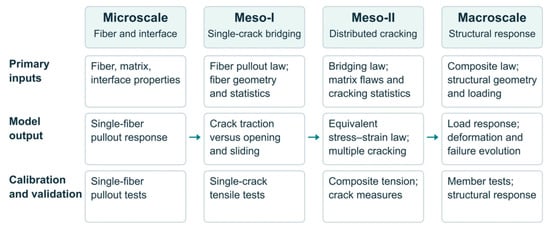
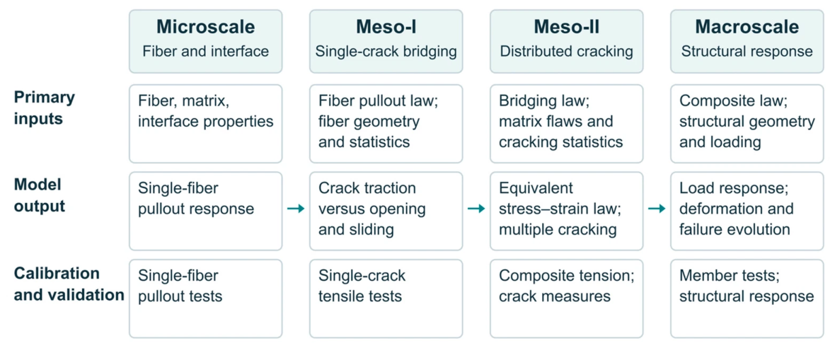
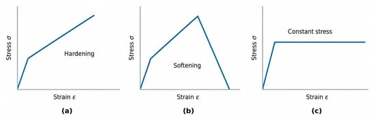
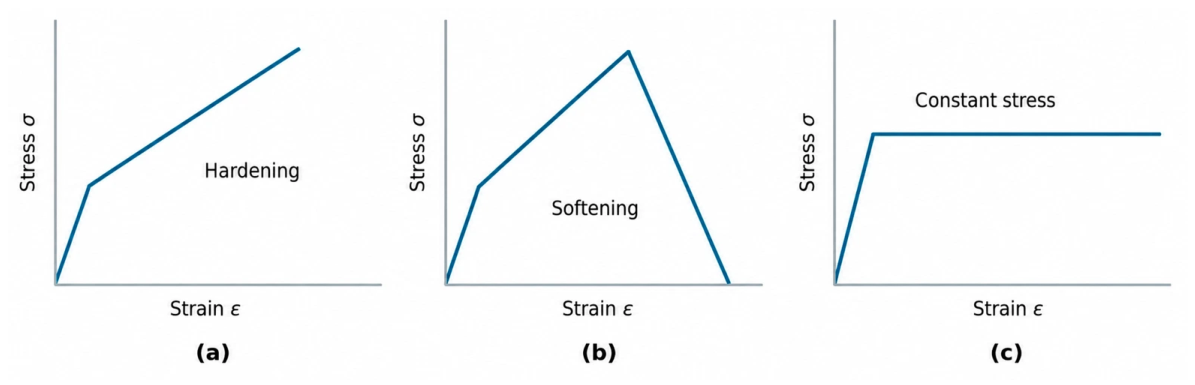
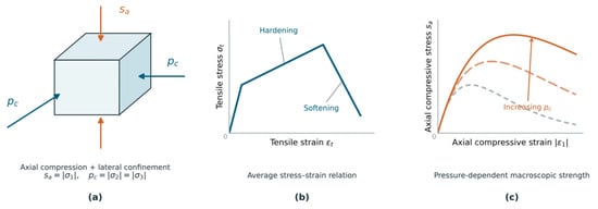
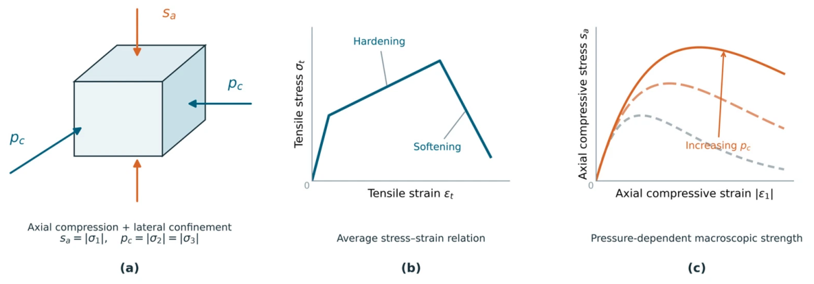
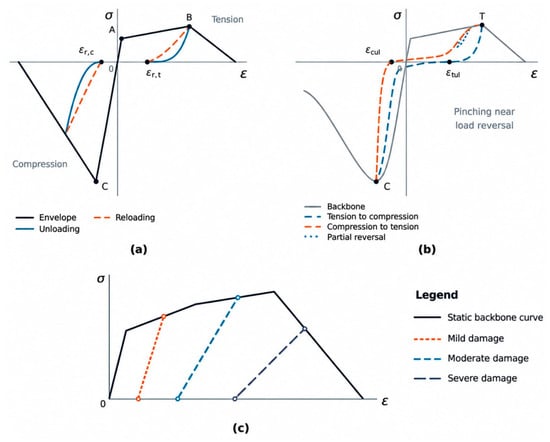
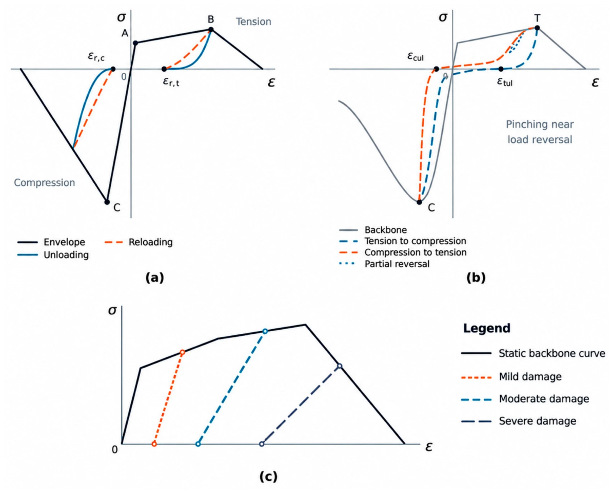
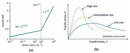
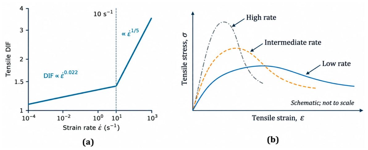
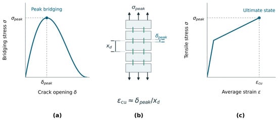
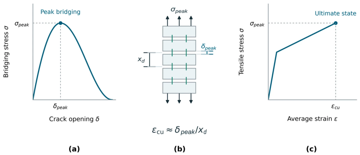
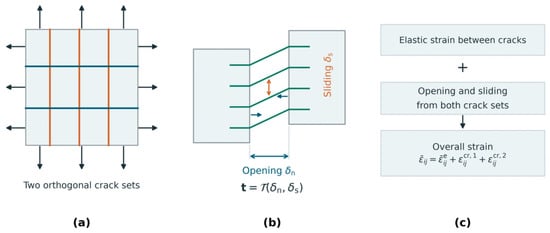
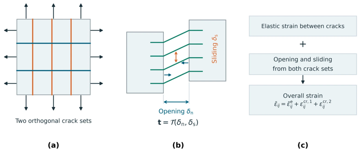
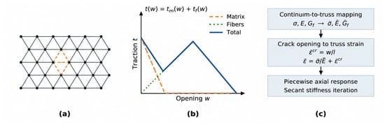
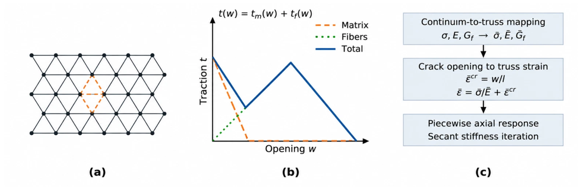
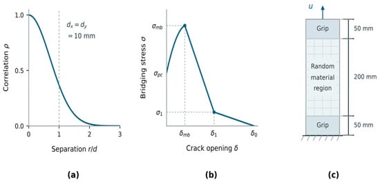
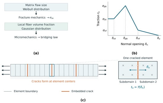
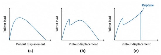
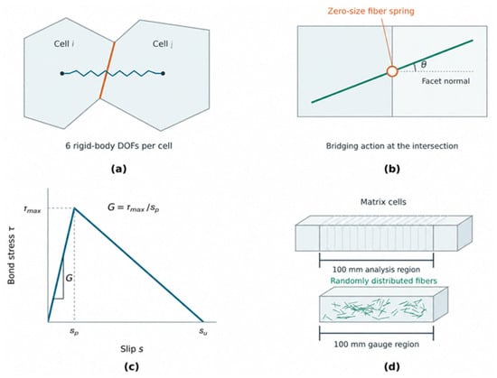
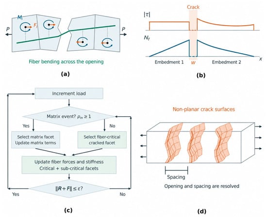
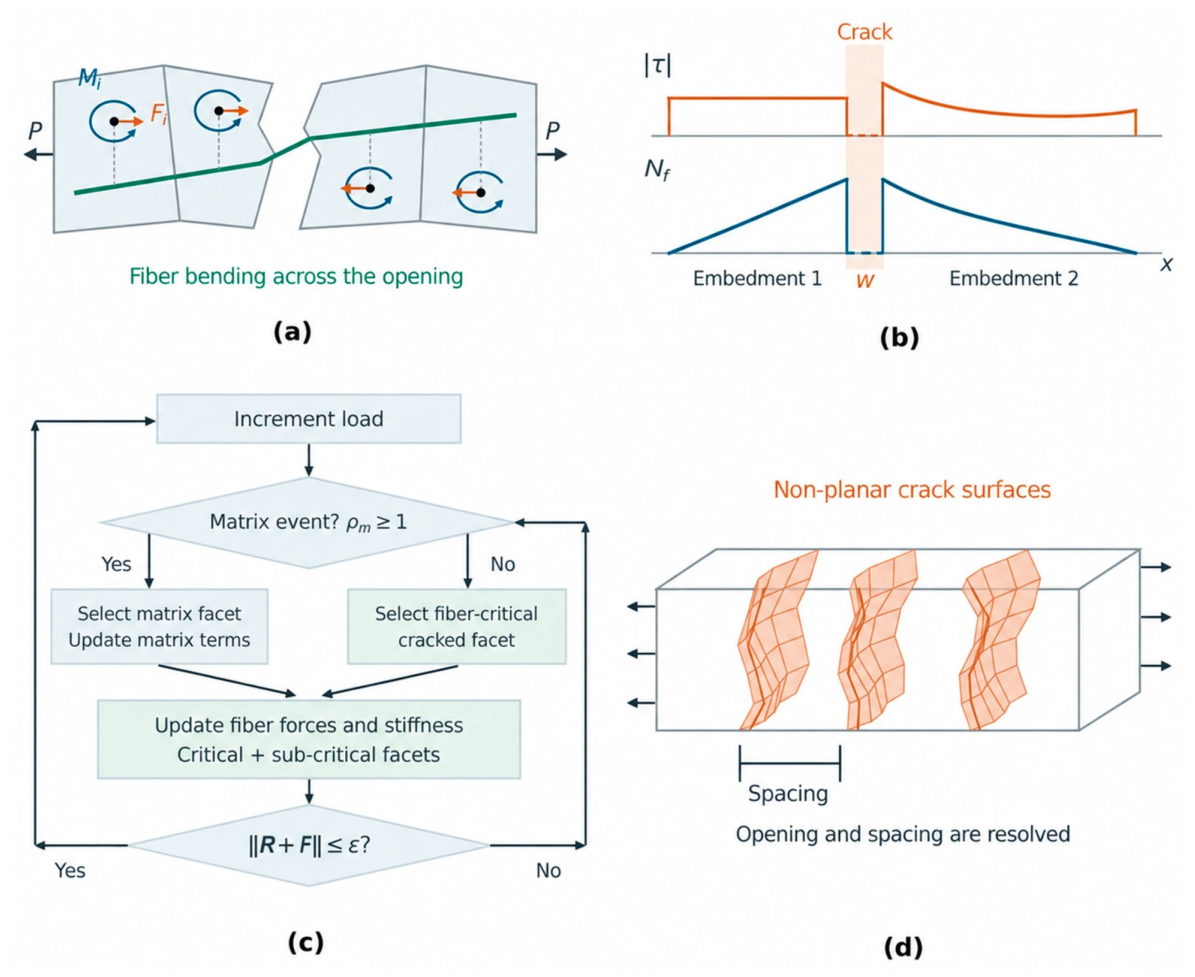
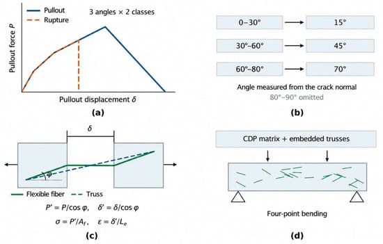
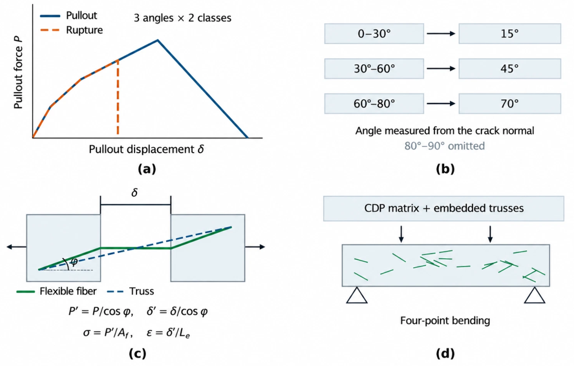
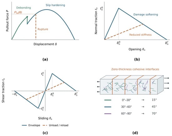
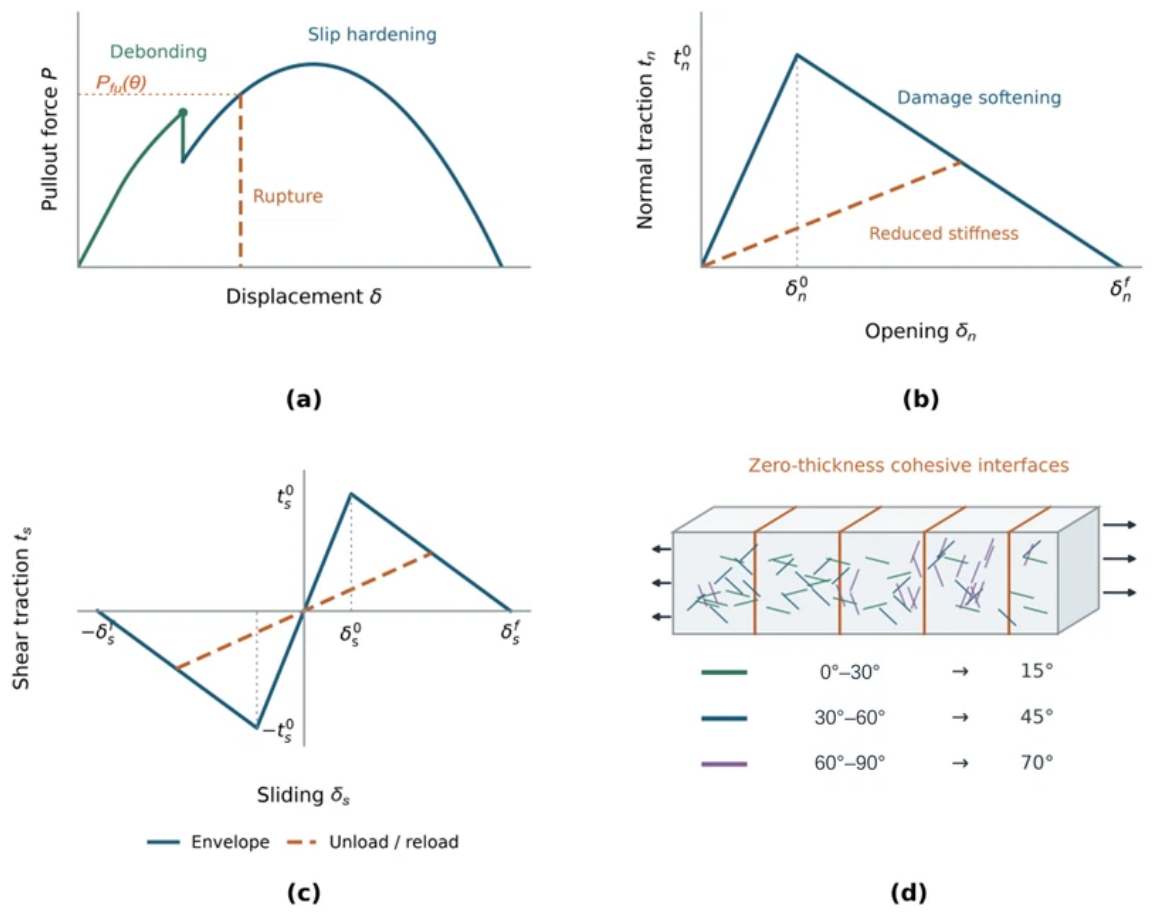
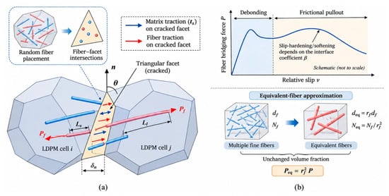
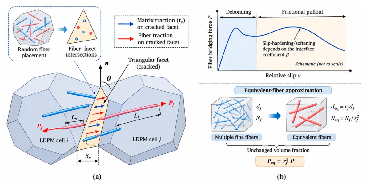
Disclaimer/Publisher’s Note: The statements, opinions and data contained in all publications are solely those of the individual author(s) and contributor(s) and not of MDPI and/or the editor(s). MDPI and/or the editor(s) disclaim responsibility for any injury to people or property resulting from any ideas, methods, instructions or products referred to in the content. |
© 2026 by the authors. Licensee MDPI, Basel, Switzerland. This article is an open access article distributed under the terms and conditions of the Creative Commons Attribution (CC BY) license.