


Abstract
In this study, HC420LA steel plates joined by gas metal arc welding (MAG), manual laser welding (ML), and robotic laser welding (RL) were comparatively examined under heat input (HI) levels obtained from an active production line exhibiting weld defects. The effect of HI and welding method on mechanical properties, microstructural evolution, phase characteristics, and weld integrity was evaluated using tensile and hardness tests, scanning electron microscopy (SEM), energy-dispersive X-ray spectroscopy (EDS), and X-ray diffraction (XRD). Weld imperfections were evaluated according to ISO 5817:2023(E) for MAG welds and BS EN ISO 13919-1:2019 for laser welds, and the corresponding quality levels were determined. The highest tensile strength (568 MPa) and elongation (23%) were achieved in RL welds at the lowest HI value (0.108 kJ/mm), with fracture occurring outside the weld region, indicating superior joint integrity and mechanical compatibility with the base metal. In contrast, MAG and ML welds exhibited a non-linear relationship between HI and ductility and tensile strength. ML welds showed higher hardness and reduced ductility due to the formation of harder transformation products, while MAG welds demonstrated a non-linear response associated with heat-affected zone (HAZ) coarsening. Heterogeneous phase distribution XRD analysis confirmed the presence of α-Fe-based phases and secondary alloyed structures, while EDS analyses revealed a relatively homogeneous distribution of the principal alloying elements within the weld regions and provided supporting evidence for the Mn3O4 oxide phase identified in the RL welds. SEM observations further demonstrated distinct microstructural transitions across the fusion zone (FZ) and HAZ, reflecting the influence of the welding process and heat input on weld evolution. The assessment of weld imperfections according to the relevant ISO standards showed that ML and RL welds satisfied Quality Level B, whereas MAG welds exhibited quality levels ranging from B to D, depending on the evaluated imperfection. These results indicate that equivalent HI values do not guarantee comparable weld quality or mechanical performance across different welding processes. The study provides insight into the relationship between heat input, weld quality, microstructural evolution, phase constitution, and mechanical performance in HSLA steels.
1. Introduction
Increasing demands for lightweight, cost-effective, and mechanically reliable structures in the railway and automotive industries have accelerated the use of high-strength low-alloy (HSLA) steels. These steels, also known as micro-alloyed steels, offer an advantageous strength-to-weight ratio and are widely used in applications requiring high mechanical performance and weldability. Their properties are achieved through low carbon content combined with alloying elements such as Mo, Nb, Ti, and V, which enhance strength through grain refinement, precipitation hardening, and solid-solution strengthening [1,2]. HSLA steels are extensively used in automotive, railway, construction, and energy applications due to their high strength-to-weight ratio, durability, and structural reliability [3,4,5,6,7]. In railway applications, particularly load-bearing components such as seat chassis, weld quality is critical for long-term service performance and passenger safety [7].
Welding remains one of the most widely used permanent joining methods for HSLA steels. Selecting an appropriate welding process and controlling thermal history during joining are critical for ensuring structural reliability, microstructural evolution, and mechanical performance [6,8]. Process instabilities may still lead to imperfections such as porosity, undercutting, incomplete penetration, and cracking, which can adversely affect weld integrity [9,10]. Among fusion welding processes, gas metal arc welding (MAG) and laser welding are particularly relevant for lightweight structural applications due to their industrial relevance and compatibility with automation [11,12,13]. Laser welding has gained increasing attention for joining thin HSLA sheets because of its low heat input (HI), high precision, minimal distortion, and high productivity [11,14,15,16].
Heat input (HI) is a key welding parameter influencing weld geometry, cooling rate, microstructural evolution, and the resulting mechanical performance of welded joints. Increased HI generally reduces cooling rates and may promote grain coarsening, whereas insufficient HI may lead to inadequate fusion or penetration [14,17,18]. Laser welding processes typically operate at power densities on the order of 106–108 W/cm2, which is significantly higher than conventional arc methods, allowing for deep penetration with relatively low linear HI [19]. This high energy density is typically associated with rapid cooling cycles that facilitate finer microstructures in both the fusion zone (FZ) and the heat-affected zone (HAZ) [20,21,22]. Comparable thermal–microstructural relationships have also been discussed in arc-based additive manufacturing systems, where thermal input and cooling history strongly influence phase evolution and mechanical behavior [23,24,25].
Among cold-formable HSLA grades specified in DIN EN 10268:2006+A1:2013 [26], HC420LA is widely used in lightweight structural applications requiring a balance of strength, ductility, and weldability [27]. Under conventional conditions, its microstructure is predominantly composed of polygonal ferrite with fine pearlitic constituents, which contributes to its favorable combination of formability and mechanical strength [2,28,29]. Reported mechanical properties typically include yield strengths in the range of 420–520 MPa and ultimate tensile strengths of approximately 470–590 MPa, supporting its suitability for demanding automotive and railway structural applications [29,30,31]. However, as with other thin HSLA steels, welding thermal cycles may significantly alter the local microstructure through phase transformation, residual stress development, hardness variation, and heat-affected zone (HAZ) softening, which may ultimately affect weld integrity and mechanical performance [2,30]. In laser-welded HC420LA joints, the fusion zone (FZ) has been reported to exhibit ferritic–bainitic microstructures associated with rapid thermal cycling, while microstructural heterogeneity across the HAZ may adversely influence weld integrity and mechanical behavior [2,28,30]. Previous studies on HC420LA and related HSLA steels further indicate that weld quality is highly sensitive to thermal input and process parameter selection; insufficient heat input may lead to incomplete fusion, whereas excessive thermal exposure may promote HAZ softening, localized defects, and deterioration of mechanical performance [2,28,30,31].
As thermal history influences not only microstructural development but also weld morphology and imperfection formation, standardized weld quality criteria provide an objective basis for industrial assessment of weld discontinuities. However, overall welded joint performance cannot be evaluated solely on the basis of geometric acceptance criteria but must also be interpreted in conjunction with microstructural evolution and mechanical behavior. Therefore, weld quality assessment standards such as EN ISO 5817:2023 [32] for fusion welding and BS EN ISO 13919-1:2019 [33] for laser beam welding were adopted in this study specifically for the classification of weld imperfections within a broader experimental evaluation framework. The motivation for this study arises from weld imperfections observed during industrial production of HC420LA railway seat chassis components under existing joining conditions. In this context, manual laser (ML), robotic laser (RL), and MAG welding—three industrially relevant joining approaches differing in automation level, process flexibility, and thermal characteristics—were comparatively investigated under nominally comparable heat input conditions derived from production parameters. Although previous studies have examined welding of HSLA steels, comparative investigations on HC420LA involving these three joining methods remain limited. Accordingly, this study evaluates the influence of welding method and HI on weld quality, microstructural evolution, and mechanical performance using SEM, XRD, and complementary EDS characterization alongside ISO-based imperfection assessment.
2. Materials and Methods
In this study, HSLA cold-rolled and uncoated HC420LA (1.0556) steel was selected as the base material. Its chemical composition is presented in Table 1. Beyond its high strength, HC420LA exhibits superior crashworthiness and impacts energy absorption, making it suitable for components and spare parts in the automotive and railway industries [34].
Table 1.
The chemical composition of the HC420LA steel (in wt., %).
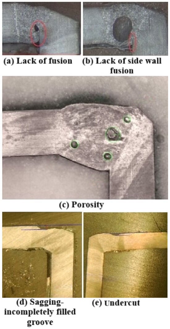
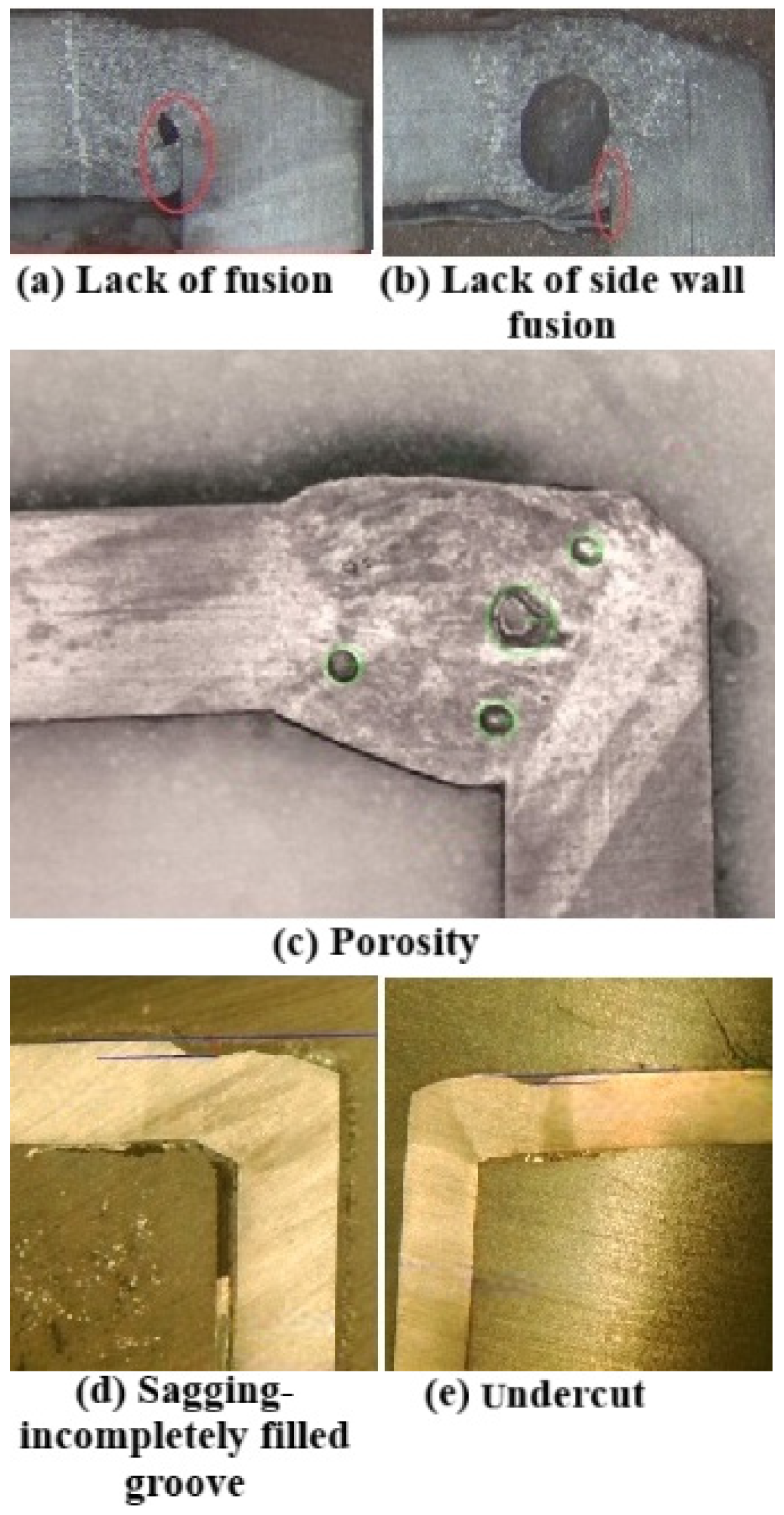
The experimental design of this study was motivated by weld imperfections observed during industrial production of HC420LA railway seat chassis components under the existing laser welding conditions, particularly at a heat input (HI) of 0.168 kJ/mm (Figure 1). Since weld quality in thin HSLA steels is strongly influenced by both heat input and process-specific characteristics, the present study was designed to investigate the effect of reduced heat input levels as well as alternative joining approaches. For this purpose, manual laser (ML), robotic laser (RL), and MAG welding were comparatively evaluated under nominally comparable heat input conditions to assess differences in weld quality, microstructural evolution, and mechanical performance. These three joining approaches were selected due to their industrial relevance and practical applicability in lightweight structural manufacturing.
Figure 1.
Representative weld imperfections observed in HC420LA components under the original industrial laser welding condition (HI = 0.168 kJ/mm).
All welding operations were conducted at Askon Demir Çelik Sanayi ve Ticaret A.Ş. (Askon Iron & Steel Industrial Inc., Denizli, Türkiye). Uncoated HC420LA steel sheets were cut into specimens measuring 50 mm × 100 mm × 2 mm. The samples were prepared in a square butt joint (I-joint) configuration, considering the general joint preparation principles for thin-sheet butt welding described in ISO 9692-1 [35]. Due to the 2 mm sheet thickness, no groove preparation was required. No intentional gap was introduced between the sheets, and the same joint geometry was maintained for all welding methods to ensure comparability. Prior to welding, surface oxides and contaminants were mechanically removed by wire brushing and sanding, followed by acetone cleaning to remove oil, grease, and residual organic contaminants. No additional process-specific surface preparation was applied for MAG welding. All welding procedures were performed in a single pass.
MAG welding was performed using a water-cooled Fronius TPS 500i MIG-MAG welding machine (Fronius International GmbH, Pettenbach, Austria) with a welding current capacity of 500 A [36]. Magmaweld MG2 (G 42 4 M21 G 3Si1—EN ISO 14341-A) filler wire (Magmaweld, Manisa, Türkiye) with a diameter of 0.8 mm was used as the consumable electrode [37]. According to the manufacturer’s technical specifications, the filler metal contains approximately 0.07 wt.% C, 0.90 wt.% Si, and 1.45 wt.% Mn, with typical mechanical properties including a yield strength of 430–460 MPa, tensile strength of 540–560 MPa, and elongation of 27–29% [38]. The selected filler wire is suitable for structural steel welding applications. HB-212 shielding gas (Ar-based, 12% CO2 and 2% O2; ISO 14175, M21 classification) was used during MAG welding.
Manual laser (ML) welding was performed using a water-cooled Lasersonic LHW 1500 handheld fiber laser system (Lasersonic, Bursa, Türkiye) with a nominal maximum power output of 1500 W [39]. Handheld fiber laser welding is increasingly used in thin-sheet joining applications due to its concentrated energy input, reduced thermal distortion, and operational flexibility compared with conventional arc-based manual welding methods [40,41,42]. The experimental ML welding parameters are summarized in Table 2. Welding was conducted at a constant travel speed of 10 mm/s using laser power levels between 1200 and 1500 W, corresponding to heat input values of 0.108–0.135 kJ/mm. Pure argon was used as the shielding gas to protect the weld pool from atmospheric contamination and reduce oxidation during welding.
Table 2.
Laser welding parameters.
Robotic laser (RL) welding was performed using a CorActive CFLS-4000 CW fibre laser system (CorActive High-Tech Inc., Quebec City, QC, Canada) with a nominal maximum power output of 4000 W [43]. The experimental RL parameters are listed in Table 2. Welding was conducted at a constant travel speed of 20 mm/s using laser power levels between 2400 and 3000 W, corresponding to HI values of 0.108–0.135 kJ/mm. Pure argon was used as the shielding gas during RL welding.
Heat input (HI) during welding was calculated according to Equations (1) and (2) for laser and MAG welding, respectively [17,18,44]. In Equation (1), P is the laser power (kW), v is the travel speed (mm/s), and η is the process efficiency, assumed to be 0.9 for laser welding [44]. In Equation (2), V is the arc voltage (V), I is the welding current (A), v is the travel speed (mm/s), and η is the arc efficiency factor, fixed at 0.8 for MAG welding according to EN ISO 1011-1 [45]. The selected welding parameters were designed to produce nominally comparable HI values across ML, RL, and MAG conditions, enabling systematic comparison of process stability, weld quality, microstructural evolution, and mechanical performance. However, differences in energy delivery mode and thermal distribution between processes were also considered, as these may influence cooling behavior and defect susceptibility. The corresponding experimental parameters are summarized in Table 2 and Table 3.
HI = η∙P/v
HI = η∙V∙I/v
Table 3.
MAG welding parameters.
In the design of the study, it was recognized that identical nominal heat input values do not necessarily correspond to identical energy densities or thermal fields. Laser welding is characterized by a substantially higher power density than MAG welding and delivers energy through a highly concentrated beam, resulting in different melting characteristics, cooling rates, and fusion zone geometries. Therefore, nominally comparable heat input values were selected to enable a systematic comparison of the welding processes. However, the inherent differences in energy delivery mechanisms and thermal distributions were taken into account when interpreting the experimental results.
Prior to SEM and XRD analyses, the welded specimens were ground successively using 100, 200, 400, 800, and 1000 grit SiC abrasive papers to remove surface irregularities, oxide layers, and burrs formed during sectioning. The surfaces were subsequently cleaned with acetone to remove oil, grease, and other organic contaminants. Specimen preparation followed the general metallographic procedures described in ASTM E3. Microstructural characterization was performed using a Schottky Field Emission Scanning Electron Microscope (FE-SEM, Zeiss Supra 40 VP, Zeiss, Oberkochen, Germany) equipped with an EDAX Element EDS system (Bruker, Berlin, Germany). The system operated under high vacuum mode (≤10−6 mbar) and the observations were performed using the SE2 detector at an accelerating voltage of 30 kV at the Pamukkale University Advanced Materials Research Center (ILTAM).
Phase identification was conducted using a Bruker D8 Advance X-ray diffractometer (Bruker, Billerica, MA, USA) at the Afyon Kocatepe University Technology Application and Research Center (TUAM). XRD measurements were performed using Cu Kα radiation (λ = 1.5406 Å) over a 2θ scanning range of 20–100°.
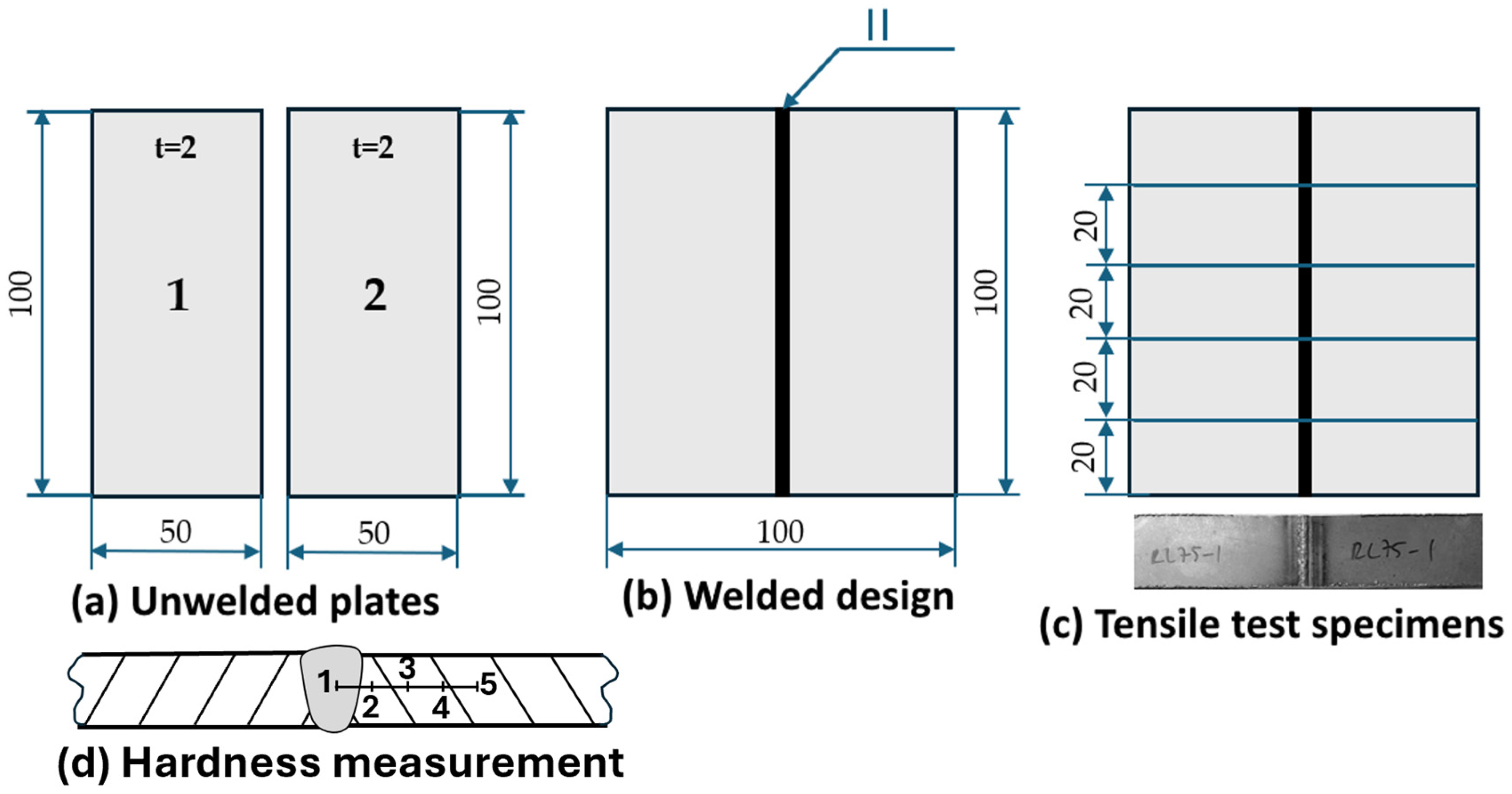
Tensile testing was conducted in accordance with DIN EN ISO 6892-1 [46] using a 10-ton universal testing machine (Hardway, MTC Metalurji, Bursa, Türkiye). The geometry and dimensions of the tensile specimens are presented in Figure 2a,b. The welded plates were initially prepared by laser cutting in accordance with the thermal cutting quality requirements of ISO 9013 (Class 1) [47]. After welding, tensile specimens were divided by mechanical sawing to avoid additional thermal effects and possible microstructural alteration. To minimize potential edge-related effects associated with weld initiation and termination, only the three centrally extracted specimens from each welded plate were selected for tensile evaluation (Figure 2c). Following extraction, specimen edges were sequentially ground using 100–1000 grit SiC abrasive papers to remove burrs and surface irregularities prior to testing. Flat tensile specimens (2 × 20 × 100 mm) were selected because the investigated material consisted of 2 mm thick welded sheets, allowing the weld centerline to coincide with the tensile loading axis so that the FZ and adjacent HAZ were subjected to the applied load. A constant crosshead speed of 20 mm/min was applied throughout the tests. Considering the effective parallel length of approximately 60 mm, this speed corresponds to a strain rate within the ±20% tolerance specified for Method A in DIN EN ISO 6892-1. The selected testing conditions therefore complied with the requirements of the standard for flat metallic specimens of this thickness. For each welding condition, three tensile specimens were tested under identical loading conditions, and the average values were used for data evaluation. The total specimen length was 100 mm, with approximately 20 mm at each end clamped during testing, resulting in an effective parallel length of approximately 60 mm. An initial gauge length (L0) of 36 mm was used for engineering elongation measurements, as defined in the tensile testing system.
Figure 2.
Dimensions and preparation of the test specimens used in this study (all dimensions are in mm). (a) Geometry and dimensions of the unwelded HC420LA plates prior to joining; (b) Schematic illustration of the welded plate configuration; (c) Extraction layout of the tensile test specimens from the welded plate; (d) Schematic representation of the Vickers hardness measurement locations across the weld cross-section.
To ascertain whether the variations in welding techniques were significant, tensile test data (Rm, Re, and A (%)) from the welded specimen groups (according to welding method ML, RL, and MAG, irrespective of HI level) were statistically assessed. For statistical evaluation, specimens were grouped. Each mechanical attribute was subjected to a separate one-way analysis of variance (one-way ANOVA) using the individual specimen data within each welding group as independent observations. Data were examined for homogeneity of variances and normality prior to analysis. Pairwise comparisons of welding techniques were carried out using a Tukey post hoc test to determine whether groups differed when the ANOVA revealed a significant effect (p < 0.05). Standard computing methods were used for all statistical analyses, and a significance level of α = 0.05 was used for every test.
Vickers hardness measurements were performed in accordance with ISO 6507-1 using a load of 1470 N (HV15) and a dwell time of 5 s [48]. Due to equipment availability limitations, macrohardness testing was employed instead of microhardness mapping; therefore, the measurements were intended to provide a comparative assessment of hardness variation across the weld region rather than fine-scale local hardness profiling. Indentations were positioned at 1 mm intervals along a transverse line crossing the weld center, covering the weld metal (FZ), heat-affected zone (HAZ), and adjacent base material (BM). Measurements were repeated three times, and average values were reported. A schematic representation of the hardness measurement locations is provided in Figure 2d.
3. Results
3.1. Mechanical Properties
3.1.1. Tensile Test Results
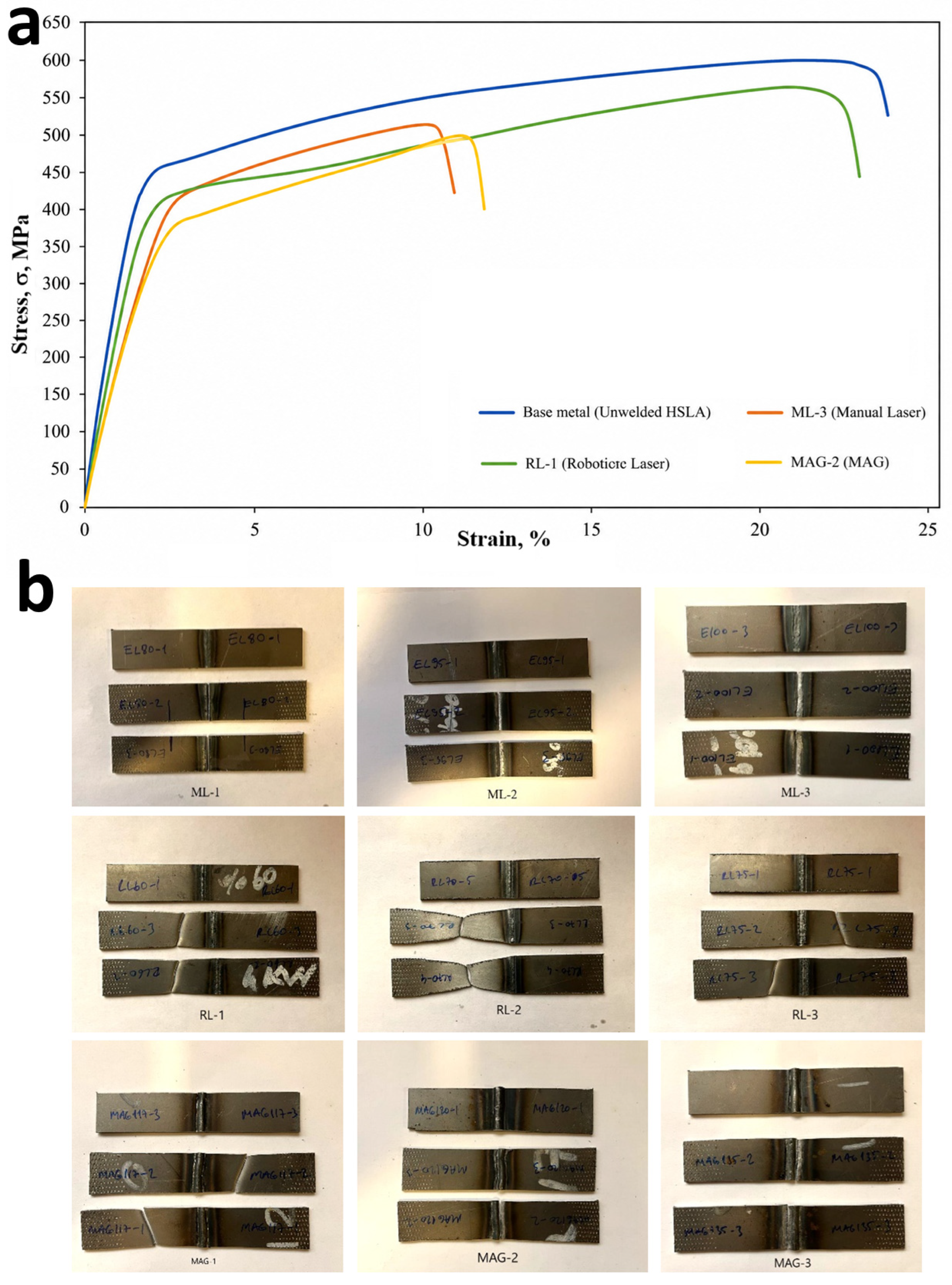
Table 4 summarizes the tensile test results for all welding parameters. The ultimate tensile strength (Rm), yield strength (Re), and elongation at break (A) of the unwelded HC420LA steel were 601.5 MPa, 504.5 MPa, and 23.75%, respectively. In contrast, the mechanical performance of the welded specimens produced via the MAG, ML, and RL processes clearly depended on the welding technique and HI. Depending on the particular procedure and settings, all welded joints showed decreases in Rm and Re in comparison to the base metal, with strength losses ranging from roughly 7% to 30%. It should be noted that the reported Re values were obtained from the global tensile response of the welded joints. Since the weld metal, HAZ, and base metal exhibit different microstructures and mechanical properties, the reported Re represents the overall behaviour of the welded assembly rather than the local yield behaviour of individual regions. Local mechanical characterization of the FZ and HAZ would require techniques such as digital image correlation, micro-tensile testing, or local indentation methods, which were beyond the scope of the present study.
Table 4.
Mechanical properties and fracture locations of HC420LA welded joints under different welding conditions.
Elongation and fracture location also showed clear variations depending on welding method and heat input. RL specimens, particularly RL-1, exhibited elongation values close to the unwelded base material and predominantly fractured outside the weld region, indicating adequate weld integrity and balanced deformation behavior. In contrast, ML specimens consistently fractured within the weld metal and showed substantially reduced elongation, suggesting localized brittleness and reduced ductility associated with process instability and thermal effects. A similar trend was observed in the MAG group, where the low-HI MAG-1 specimen fractured outside the weld seam with comparatively balanced mechanical behavior, whereas higher-HI MAG specimens fractured within the weld metal, accompanied by marked reductions in elongation and tensile strength. These observations indicate that both HI and process characteristics strongly influenced the integrity of the FZ and adjacent HAZ, likely through differences in thermal cycling, microstructural evolution, and localized softening or embrittlement.
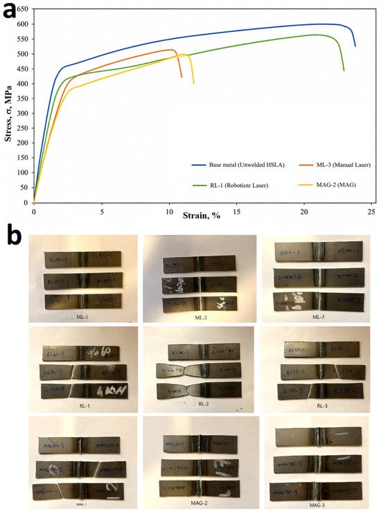
Among the laser-welded groups, ML joints showed the lowest ductility together with moderate tensile strength, with elongation remaining limited (~7–9.5%) across all HI conditions. Although some variation in Rm was observed within the ML group (465–518 MPa), no clear monotonic relationship between HI and tensile strength could be established. In contrast, RL welds exhibited improved mechanical behaviour, particularly at lower HI values. Among RL specimens, the highest tensile strength was obtained for RL-1 (568 MPa), whereas the highest elongation was observed for RL-2 (23%). This is consistent with the more pronounced necking observed for RL-2 in Figure 3. At higher HI values, RL specimens showed a gradual reduction in tensile strength, suggesting that increased thermal input adversely affected joint performance. The improved repeatability and precision of robotic control likely contributed to more consistent fusion characteristics and reduced thermal distortion, resulting in superior mechanical performance compared with ML welding.
Figure 3.
(a) Representative engineering stress–strain curves of the unwelded base material and selected welded joints (ML-3, RL-1, and MAG-2); (b) representative tensile specimens before and after testing, illustrating the fracture locations under different welding conditions.
Although the RL specimens fractured outside the weld region, their ultimate tensile strength and elongation remained slightly lower than those of the unwelded base material. This behavior can be explained by the fact that the measured tensile properties represent the global mechanical response of the entire welded joint rather than the local properties at the fracture location. During tensile loading, deformation is distributed across the base metal, heat-affected zone (HAZ), and fusion zone (FZ). Consequently, the heterogeneous microstructure produced by the welding thermal cycle, together with residual stresses and the comparatively higher stiffness of the weld region, influences the overall tensile response of the specimen. Therefore, fracture in the base metal indicates that the weld is not the weakest region of the joint, but it does not necessarily imply that the welded assembly exhibits mechanical properties identical to those of the unwelded base material.
A similar trend has been reported in the literature. Mičian et al. [49] observed that laser-welded HSLA steel joints fractured in the base metal while their yield strength and ultimate tensile strength remained approximately 90–96% of the base metal values, and elongation decreased to 23–79% of the base metal, demonstrating that base-metal fracture does not necessarily imply identical global tensile properties. Likewise, Mansur et al. [50] reported that all tensile specimens fractured away from the HAZ, confirming the absence of weld softening, although the welded joints still exhibited a slight reduction in ductility. The authors attributed the reduced elongation to the hardened weld bead, which undergoes less plastic deformation than the surrounding material, thereby decreasing the overall deformation capacity of the welded specimen. For HC420LA steel, Wang et al. [2] reported an ultimate tensile strength of 523 MPa for laser-welded joints produced using a laser power of 1.8 kW and a welding speed of 2.5 m/min. In the present study, the RL-1 condition achieved an ultimate tensile strength of 568 MPa, representing an approximately 9% improvement over the previously reported value while remaining only about 7% lower than the unwelded base material. Furthermore, under comparable heat input conditions, the RL process exhibited mechanical properties that were 2–15% higher than those obtained by ML welding, highlighting the beneficial effect of improved process stability and parameter control achieved through robotic welding.
The mechanical behavior of the MAG welding group demonstrated a non-linear dependence on HI. While high HI (MAG-3, 0.150 kJ/mm) caused noticeable softening, with Rm falling to 418 MPa and A dropping to 6%, moderate HI (MAG-2, 0.112 kJ/mm) produced the highest Rm (542 MPa). The MAG-1 sample, which had the lowest HI (0.096 kJ/mm), exhibited balanced behaviour (Rm = 522 MPa, A = 15%), suggesting that excessive thermal input may degrade joint performance through increased HAZ development and microstructural coarsening. A similar qualitative dependence of mechanical performance on heat input has been reported for other HSLA steel grades [45,51]; however, direct quantitative comparison should be made cautiously due to differences in base material strength, alloy composition, and weldability characteristics.
The representative stress–elongation curves (Figure 3a) and the corresponding fracture locations (Figure 3b) were in good agreement with the tensile test results summarized in Table 4, providing qualitative support for the measured mechanical performance. While the elongation values represent average results obtained from three specimens per condition, the fracture locations and visible deformation behaviour offer additional insight into failure modes under different welding conditions. RL specimens generally exhibited fracture outside the weld region together with more pronounced plastic deformation, consistent with their higher elongation values and improved ductility.
The more pronounced necking observed in certain RL specimens, particularly RL-2, reflects enhanced plastic deformation capacity compared with ML and higher-HI MAG conditions. In contrast, ML specimens predominantly fractured within the weld metal and showed more limited visible deformation, consistent with their substantially reduced elongation and localized brittle behaviour. A similar trend was observed in the MAG group: the low-HI MAG-1 specimen fractured outside the weld seam with comparatively balanced deformation behaviour, whereas MAG-2 and MAG-3 fractured within the weld metal, corresponding to their lower tensile strength and ductility. One specimen exhibited limited visible necking prior to fracture; while this may suggest localized premature failure associated with weld heterogeneity, definitive attribution to a specific weld defect would require additional dedicated defect characterization. Overall, these fracture characteristics support the interpretation that welding method and thermal input significantly influenced the integrity of the FZ and adjacent heat-affected regions. Similar fracture behaviour, with failure occurring outside the weld seam in ductile HSLA welded joints, has also been reported by Riofrio et al. [52].
Statistical analysis confirmed differences among the welding methods (Table 5). Rm and A showed statistically significant differences between the welding procedures (p < 0.05), while Re differences were not significant (p > 0.05), according to the one-way ANOVA results. The improved automation and regulated HI in RL welding directly improved the joint integrity and ductility, as demonstrated by post hoc analysis, which showed that RL-welded specimens had significantly higher Rm and A values compared to both ML and MAG groups. On the other hand, the MAG and ML joints exhibited significantly less elongation, which is in line with the weld seam fracture location.
Table 5.
Statistical comparison of mechanical properties between different welding methods (one-way ANOVA).
3.1.2. Hardness Analysis
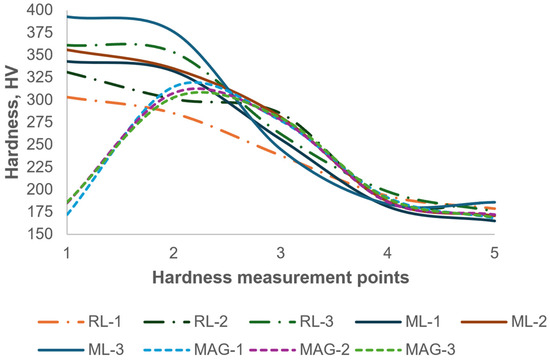
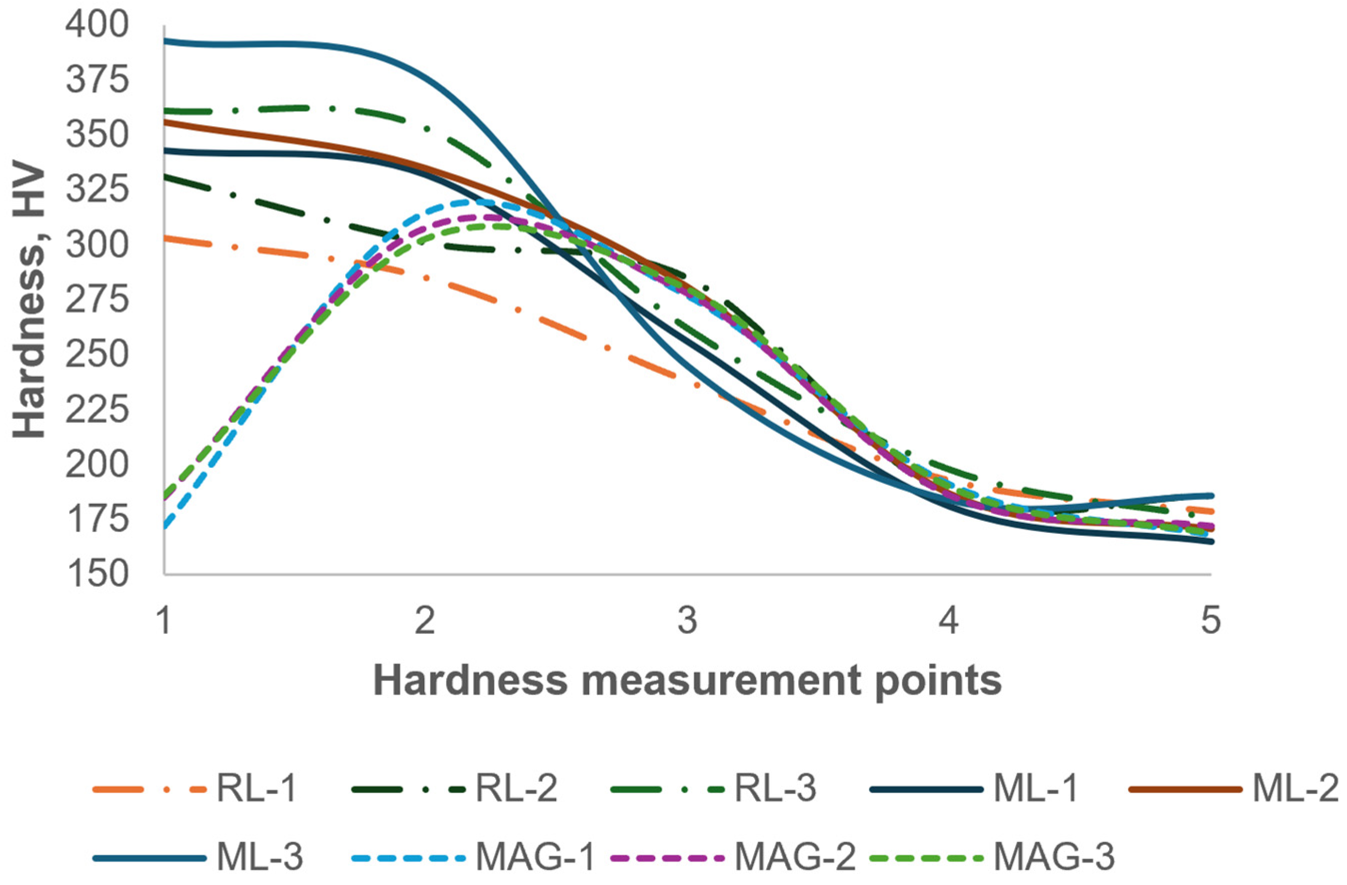
The base metal hardness was around 170 HV. As illustrated in Figure 4, laser-welded specimens exhibited the highest hardness values at the weld center, followed by a gradual decrease across the HAZ toward the base material. In both RL and ML conditions, FZ hardness increased with increasing nominal HI, with the lowest value observed in RL-1 (303 HV) and the highest in ML-3 (393 HV). Although lower heat input is commonly associated with faster cooling and higher hardness, the present results indicate that the hardness response in laser welding cannot be interpreted solely on the basis of nominal HI. The observed trend suggests that the effective thermal cycle within the fusion zone may also depend on local heat distribution and process-specific thermal characteristics, which can influence phase transformation behaviour and the resulting hardness. At 1 mm from the weld center, hardness values showed an initial decrease, while at 2 mm, values ranged between 245 and 262 HV. At 3 mm, hardness approached base metal levels, indicating a gradual hardness transition from the fusion zone toward the base material. A generally similar hardness distribution has been reported by Wang et al. [2] for laser-welded HC420LA steel; however, unlike their observations, a pronounced hardness reduction within the HAZ was not detected in the present study.
Figure 4.
Hardness distribution of the welded specimens.
The hardness measurements revealed distinct differences between welding methods. ML joints exhibited the highest FZ hardness (343–393 HV), suggesting the formation of harder transformation products associated with rapid thermal cycling, as reported for laser-welded HSLA steels [2]. However, these elevated local hardness values did not directly correspond to superior tensile strength, indicating that overall mechanical behaviour was influenced not only by local hardness but also by weld integrity, fracture location, and deformation behaviour. RL welds showed a more balanced hardness profile with moderate FZ hardness (303–361 HV) and a smoother transition toward the base metal, which was consistent with their improved ductility and predominantly base-metal fracture behaviour. A hardness peak was detected in the MAG welds, with relatively low FZ hardness (172–186 HV) but a pronounced HAZ hardness increase (≈300–315 HV), a characteristic behaviour commonly reported for GMAW of HSLA steels [51]. This hardness distribution may have contributed to the observed fracture behaviour, where MAG-1 fractured outside the weld seam, whereas MAG-2 and MAG-3 fractured within the weld metal under higher HI conditions.
3.2. Weld Appearance, Microstructure, and XRD Analyses
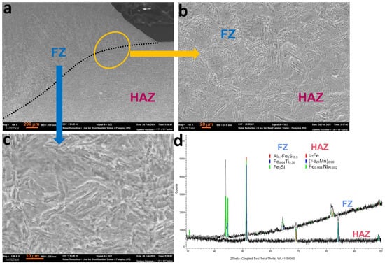
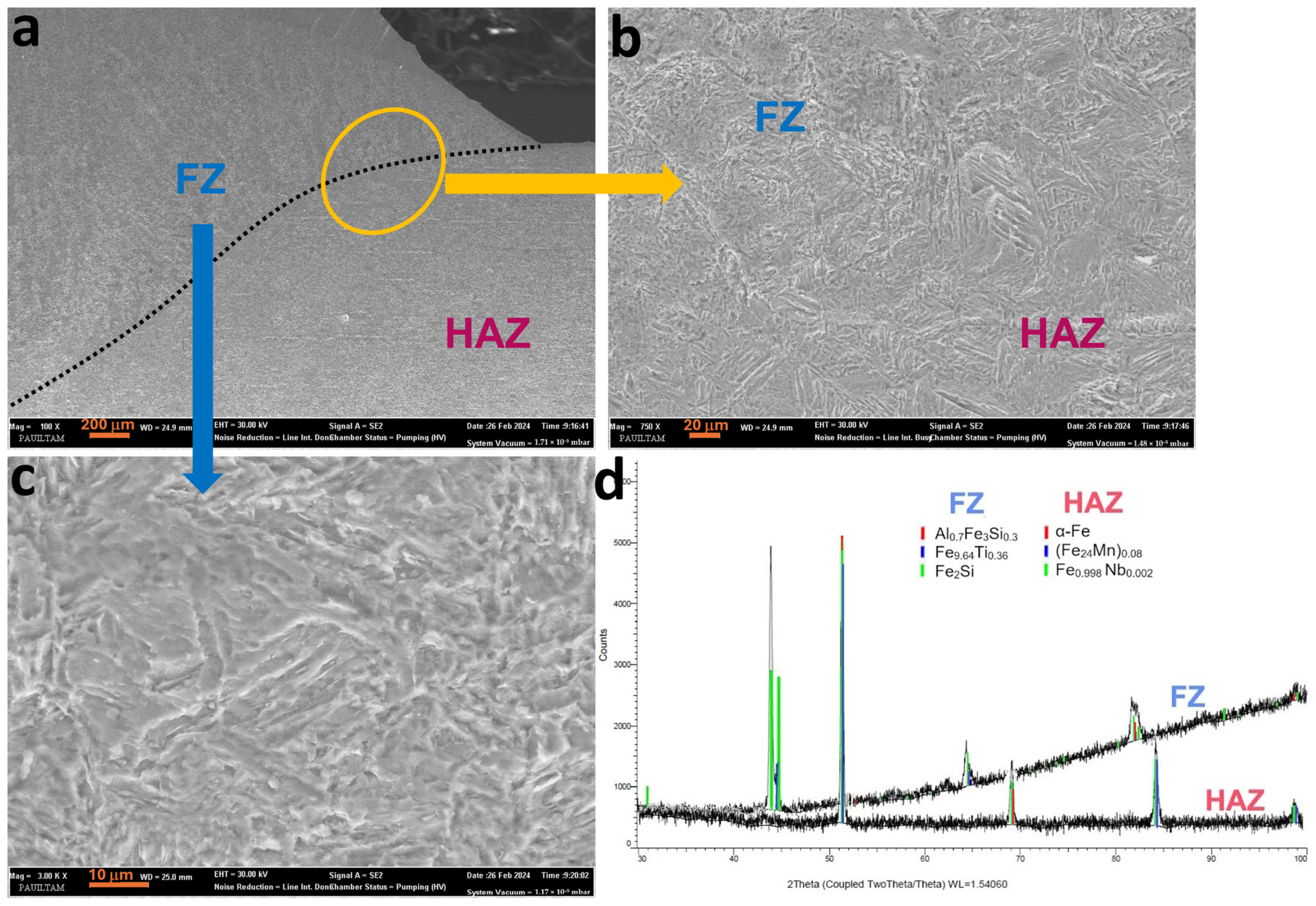
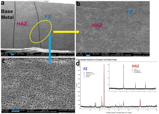
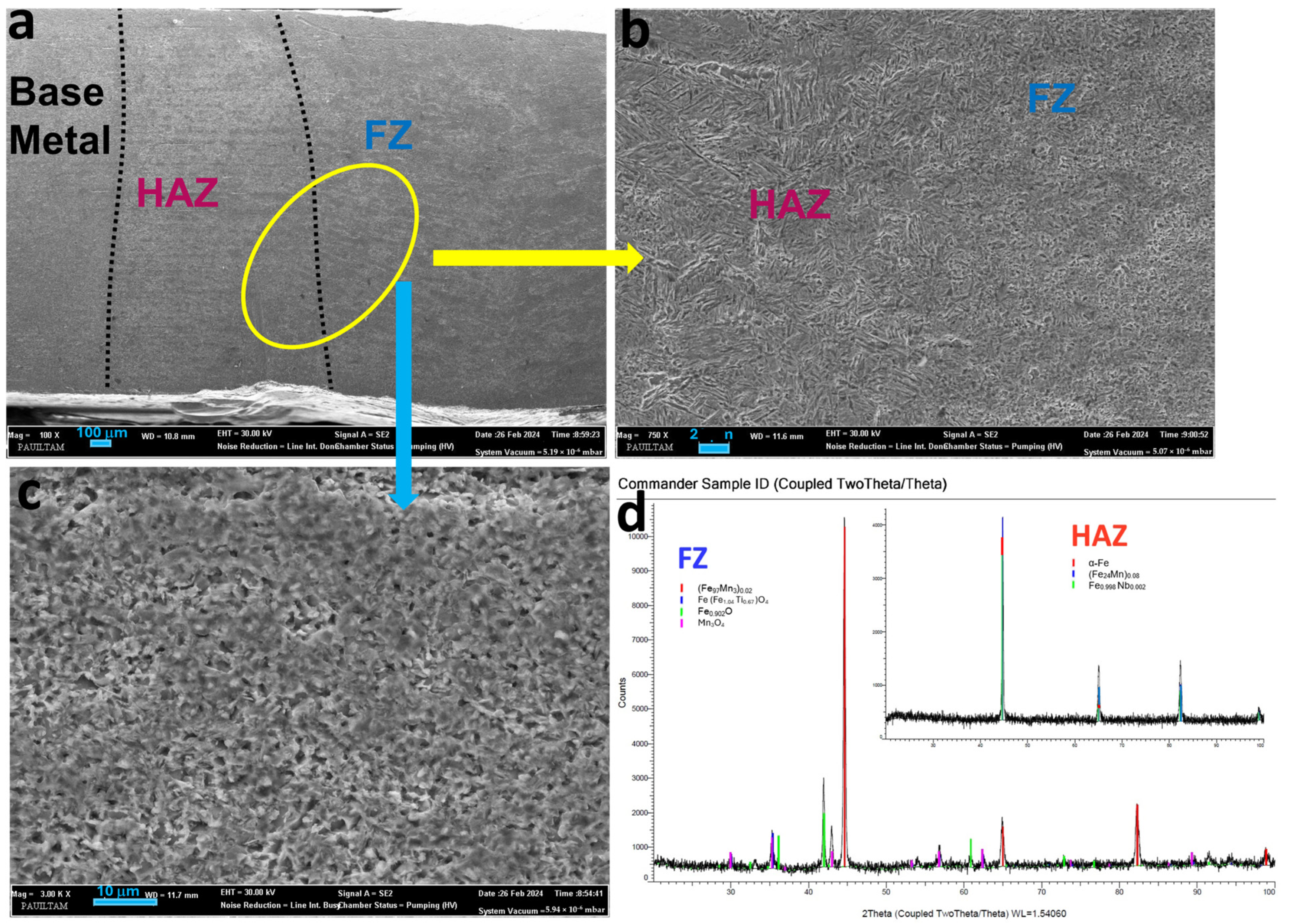
Figure 5a–c show SEM micrographs illustrating the fusion zone (FZ) and heat-affected zone (HAZ) of the MAG1 specimen welded at a heat input of 0.096 kJ/mm.
Figure 5.
Microstructural characterization and XRD analysis of the MAG-1 specimen welded at a heat input of 0.096 kJ/mm: (a) SEM image showing the fusion boundary between the fusion zone (FZ) and heat-affected zone (HAZ); (b) higher-magnification SEM image highlighting the microstructural transition between the FZ and HAZ; (c) high-magnification SEM image of the fusion zone microstructure; (d) XRD patterns obtained from the FZ and HAZ.
The fusion boundary is indicated in Figure 5a, while the higher-magnification image in Figure 5b highlights the microstructural transition between the FZ and HAZ. A relatively coarse-grained microstructure was observed in the HAZ compared with the FZ. The formation of coarse grains in the HAZ and the tendency for grain coarsening to increase with increasing HI have also been reported for pulsed gas metal arc welded HSLA steel [53]. Figure 5c shows a high-magnification SEM image of the fusion zone microstructure. The microstructural appearance of the FZ and HAZ is broadly consistent with features reported in the literature for bainitic and Widmanstätten ferrite microstructures in comparable MAG-welded HSLA steels [54].
The XRD analysis in the present study was primarily intended to identify the phase constituents formed within the weld-affected regions (FZ and HAZ), where phase transformations are expected as a result of the welding thermal cycle. Since the base material was a commercially supplied HC420LA steel with a well-documented ferritic microstructure, its phase constitution was discussed based on the available literature rather than being re-characterized experimentally. XRD results (Figure 5d) demonstrate that no oxidized phases were detected in either the weld center or the HAZ of HC420LA steel joined by MAG welding using C/Si/Mn-alloyed MG2 wire at a HI value of 0.096 kJ/mm. α-Fe, (Fe24Mn)0.08, and Fe0.998Nb0.002 phases were identified in the HAZ, whereas Al0.7Fe3Si0.3, Fe9.64Ti0.36, and Fe2Si phases were detected in the weld center.
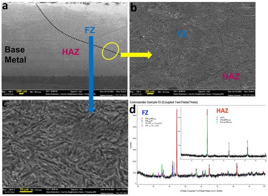
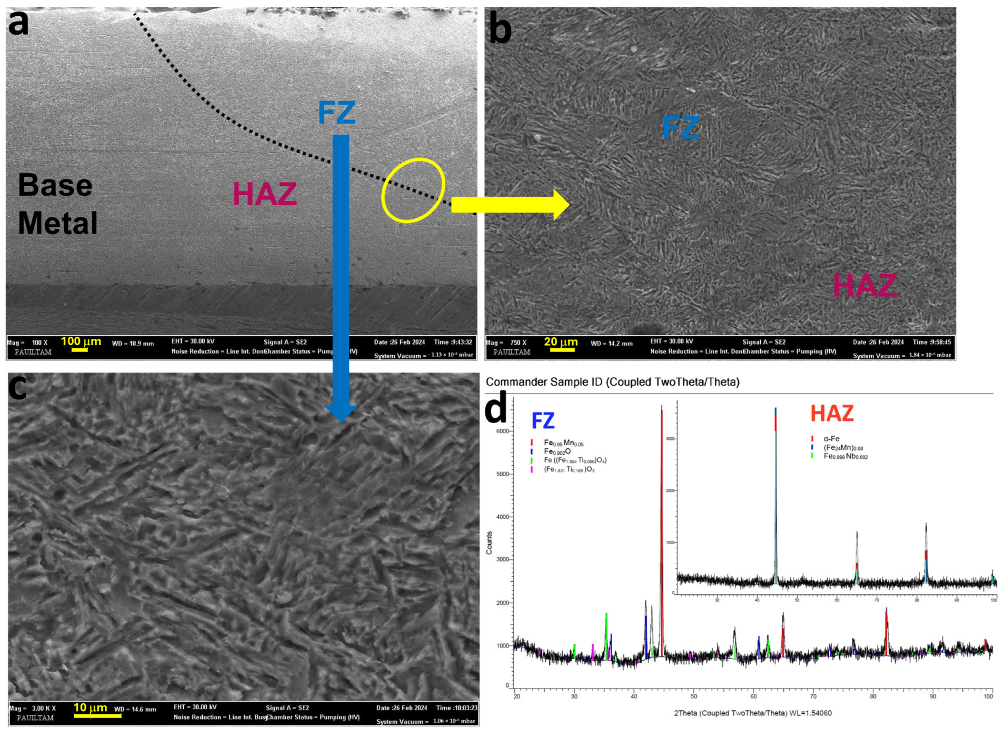
Figure 6a–c illustrate the base metal, HAZ, and FZ of the ML-3 specimen. The fusion boundary is indicated by the dashed line. Figure 6b presents a higher-magnification SEM image of the selected region, highlighting the microstructural transition between the FZ and HAZ. The weld region exhibits a finer lath- and needle-like morphology (Figure 6c), reflecting the thermal cycles associated with laser welding. Similar microstructural features have been reported in welded HSLA steels subjected to rapid heating and cooling conditions [7].
Figure 6.
Microstructural characterization and XRD analysis of the ML-3 specimen welded at a heat input of 0.135 kJ/mm: (a) SEM image showing the base metal, heat-affected zone (HAZ), fusion zone (FZ), and fusion boundary; (b) higher-magnification SEM image highlighting the microstructural transition between the FZ and HAZ; (c) high-magnification SEM image of the fusion zone microstructure; (d) XRD patterns obtained from the FZ and HAZ.
XRD analyses were conducted on the ML-3 (Figure 6d) specimen, which exhibited the highest tensile strength values in their respective groups. The phases identified in the HAZ included α-Fe, (Fe24Mn)0.08, Fe0.998Nb0.002. No oxidized structures were detected in the HAZ, while oxidized structures were detected in the FZ.
Figure 7 shows the morphology and XRD results of welds joined using the RL method. Consistent welds were obtained across all three HI levels. Figure 7a illustrates the base metal, HAZ, and FZ of the RL-1 specimen. The fusion boundaries are indicated by the dashed lines. Figure 7b presents a higher-magnification SEM image of the FZ, while Figure 7c highlights the microstructural transition between the HAZ and FZ. The weld region exhibits a finer lath- and needle-like morphology, reflecting the rapid thermal cycles associated with laser welding. Similar microstructural features have been reported in welded HSLA steels subjected to rapid heating and cooling conditions [55,56].
Figure 7.
Microstructural characterization and XRD analysis of the RL-1 specimen welded at a heat input of 0.108 kJ/mm: (a) SEM image showing the base metal, heat-affected zone (HAZ), fusion zone (FZ), and fusion boundary; (b) higher-magnification SEM image highlighting the microstructural transition between the FZ and HAZ; (c) high-magnification SEM image of the fusion zone microstructure; (d) XRD patterns obtained from the FZ and HAZ.
In contrast to the ML welds, an increase in weld discontinuities was observed with increasing HI in the RL welds, indicating different responses of the two welding approaches to increasing heat input. Similar observations have been reported for autogenous laser welding of HSLA steels, where weld defects such as undercut, spatter, and humping became more pronounced with increasing HI [15]. In the present study, a similar trend was observed for RL welding; however, ML welding exhibited a reduction in weld discontinuities as HI increased. Previous studies have reported that hand-held laser welding systems may exhibit lower process stability than fully automated laser welding systems [41,42]. In addition, inadequate control of ionized gases and vapor plume dynamics during laser welding may promote porosity formation and weld discontinuities [42]. These factors may contribute to the contrasting behaviour observed between ML and RL welding in the present study.
XRD analysis (Figure 7d) showed that, similar to the ML method, the phases identified in the HAZ included α-Fe, (Fe24Mn)0.08, and Fe0.998Nb0.002. No oxidized phases were detected in the HAZ, whereas oxidized phases were identified in the FZ. A notable difference between the ML and RL specimens was the detection of Mn3O4 in the FZ of the RL-1 sample, which was absent in the ML-3 sample. Although Mn3O4 has been reported in applications related to oxidation resistance and protective oxide formation [57,58], its direct influence on the mechanical behaviour of welded HC420LA steel remains unclear and requires further investigation.
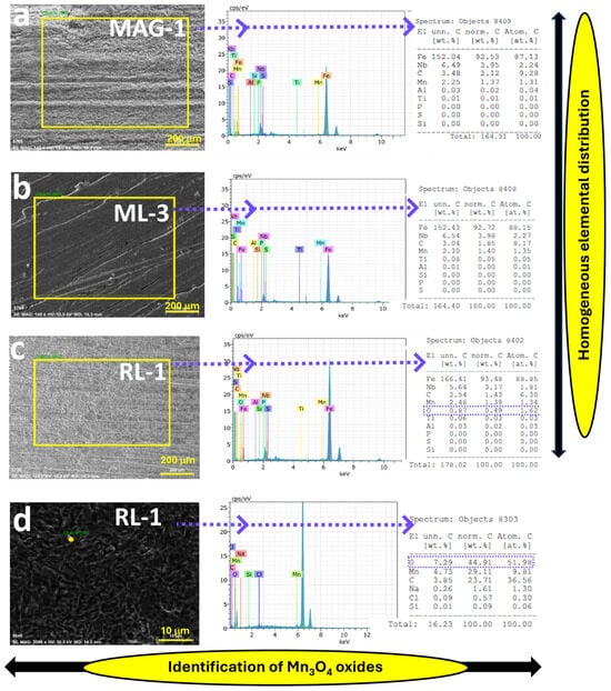
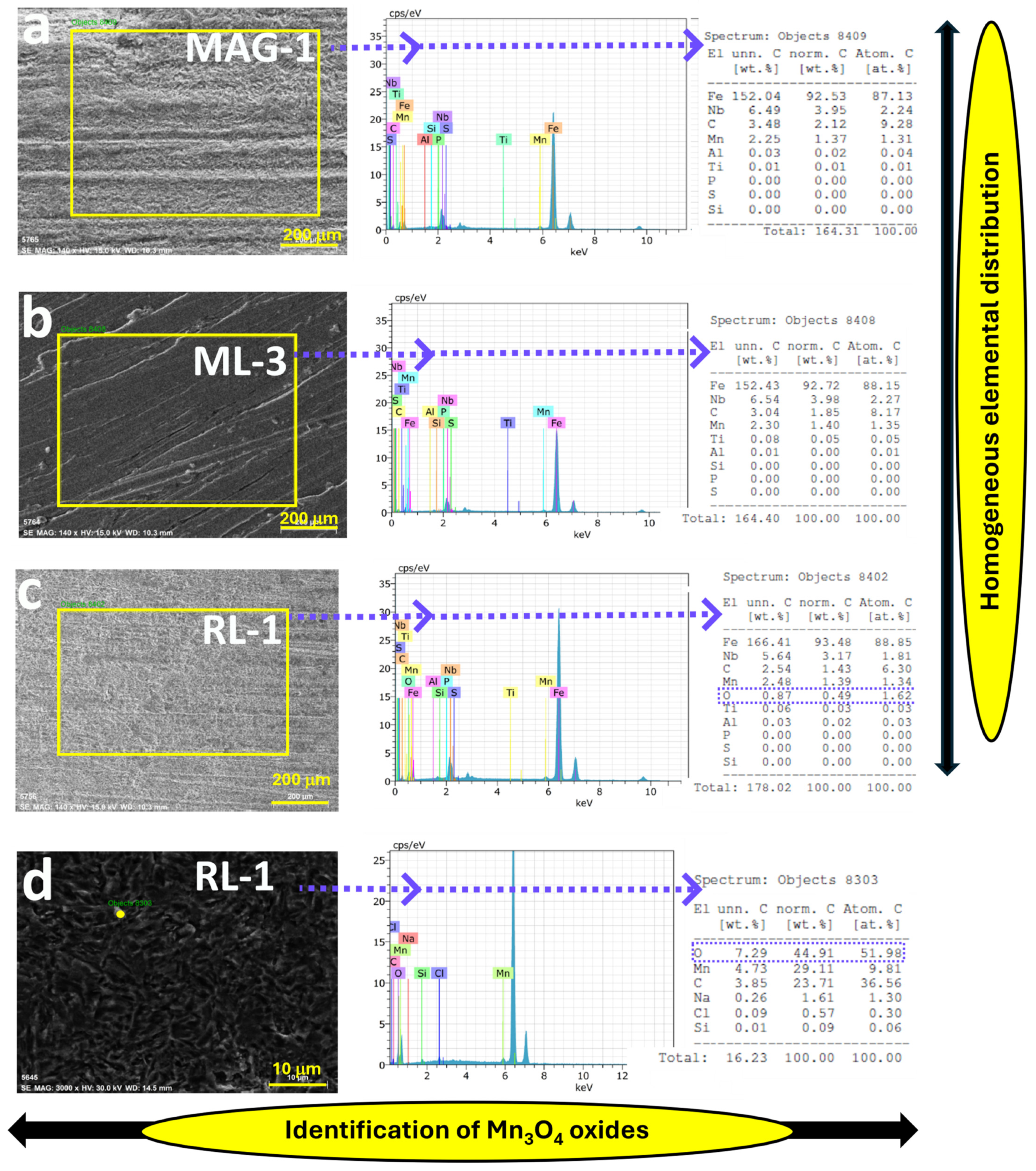
To provide a more comprehensive characterization of the microstructural evolution and the distribution of alloying elements in the weld zones, detailed EDS analyses were integrated into the study (Figure 8). Representative EDS analyses were performed on the MAG-1, ML-3, and RL-1 specimens to evaluate the elemental distribution within the weld regions. It was found that critical microalloying elements, particularly Nb and Mn, are distributed quite homogeneously throughout the matrix in MAG-1 (Figure 8a), ML-3 (Figure 8b), and RL-1 (Figure 8c), respectively. The homogeneous distribution of Nb detected by EDS is consistent with the Nb-containing phases identified by XRD (Fe0.998Nb0.002) in both the fusion and HAZ. Similarly, the measured Mn distribution is consistent with the Mn-containing phases identified by XRD (Fe24Mn)0.08. Localized point analysis (Figure 8d) under the RL-1 condition revealed micro-scale areas with significantly high concentrations of manganese (29.11 wt%) and oxygen (44.91 wt%) but the overall matrix remained mostly devoid of significant oxidation. These localized chemical enrichments provide supporting evidence for the formation of Mn3O4 detected by XRD, thereby strengthening the correlation between the elemental distribution, phase constitution, and microstructural evolution of the welded joints.
Figure 8.
Comprehensive EDS analysis of HC420LA welded joints: (a–c) Representative area mappings and spectra for MAG-1, ML-3, and RL-1 specimens, confirming a homogeneous distribution of Fe, Nb (~3.17–3.98 wt.%), and Mn (~1.4 wt.%), consistent with the XRD results; (d) Detailed point analysis of a microscopic feature in the RL-1 condition revealing significantly high O (44.91 wt.%) and Mn (29.11 wt.%) concentrations, providing direct chemical evidence for the oxide phase detected in XRD.
The correlation between heat input (HI) management and microstructural refinement observed in this study shares strong metallurgical parallels with recent advancements in arc-based additive manufacturing (WAAM) of HSLA steels. Research by Panchenko et al. (2022) highlights that the final microstructure of HSLA-WAAM components is partitioned into distinct zones: an upper ‘no-diffusion’ zone governed by the cooling rate and a lower ‘tempered’ zone determined by thermal residence time, which aligns with our findings regarding the role of HI in shaping the morphology of bainitic and ferritic phases [23]. Similarly, Kumari et al. (2025) demonstrated that while cooling rates vary during multi-layer deposition, the resulting bainitic–martensitic distributions remain relatively homogeneous with low anisotropy, corroborating the stable elemental partitioning we observed in both laser and MAG joints [24].
The systemic reviews by Mohd Ghazali et al. (2025) [25] and Kang et al. (2025) [59] underscore that managing complex thermal cycles is the primary challenge in high-strength fabrication, as heat accumulation can induce grain coarsening and localized overheating. Furthermore, advancements in post-deposition strategies, such as the normalizing heat treatments discussed by Fonseca et al. (2025), illustrate how controlled thermal processing can restore mechanical properties and refine grain structures compromised by successive thermal cycles [60]. These parallels confirm that the precise control of solidification kinetics and localized thermal cycles is a universal necessity for ensuring the structural reliability of advanced HSLA steel fabrications, whether produced through permanent joining or additive techniques.
3.3. Analysis of the Welds in Accordance with ISO 5817 and ISO 13919-1
3.3.1. Evaluation of MAG Welding
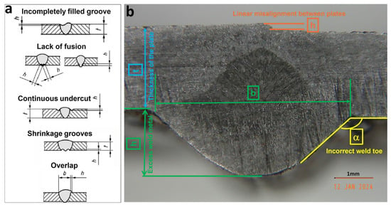
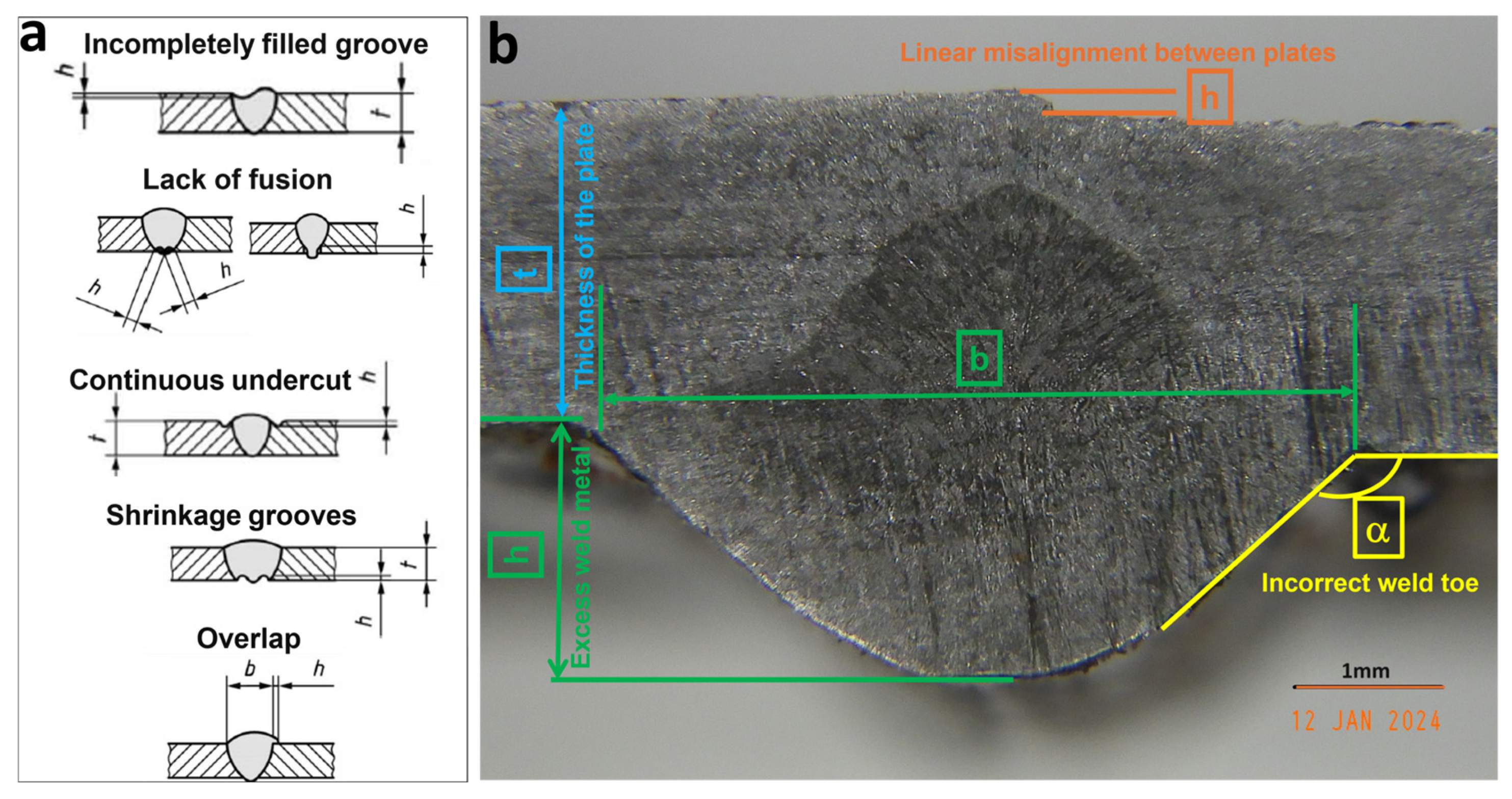
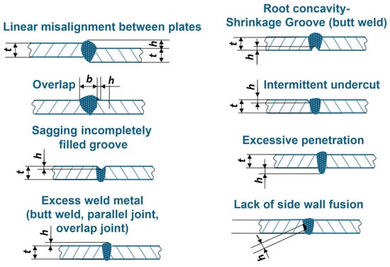
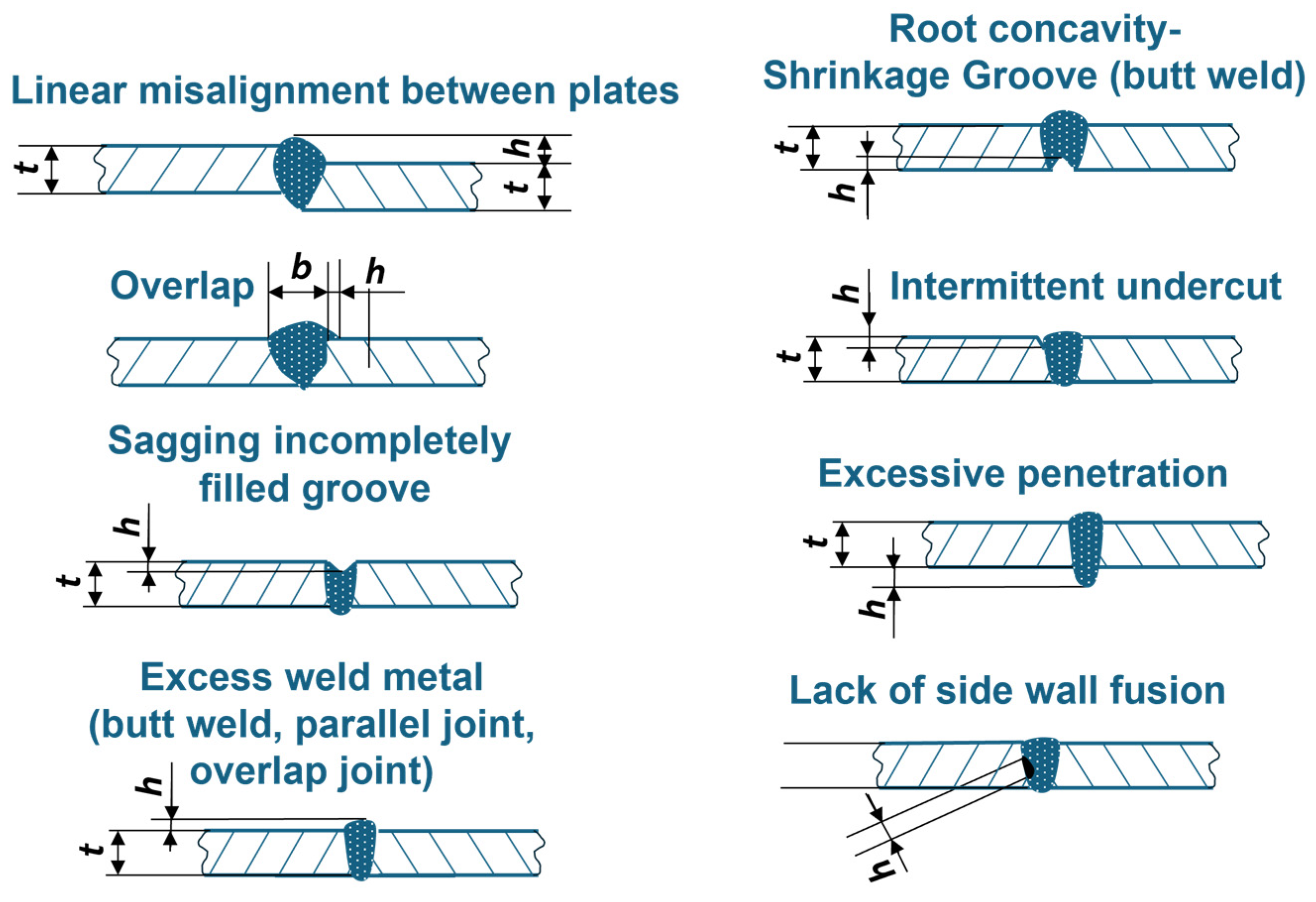
The analysis of the welded joints obtained by the MAG method was performed in accordance with ISO 5817:2023(E) (Welding—Fusion-welded joints in steel, nickel, titanium and their alloys (beam welding excluded)—Quality levels for imperfections). This standard specifies typical imperfections and their dimensions that may occur in welded joints during fabrication. It provides three sets of dimensional values to choose from, depending on the application. In the ranking of quality levels D, C, and B specified in the ISO 5817:2023(E) standard, B is considered the highest quality. According to the standard, the following defects based on only weld geometry are considered in weld analyses: lack of fusion (incomplete fusion), continuous undercut, shrinkage grooves, excess weld metal (butt weld), excessive penetration, incorrect weld toe, overlap, incompletely filled groove, root concavity, and linear misalignment between plates (Figure 9a). Imperfection limits for quality levels are determined according to the measurements and angle shown in Figure 9b.
Figure 9.
(a) Schematic representation of typical welding imperfections adapted from ISO 5817:2023(E); (b) measurements and angles used to determine the defects and quality classes identified in this study [32].
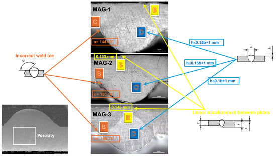
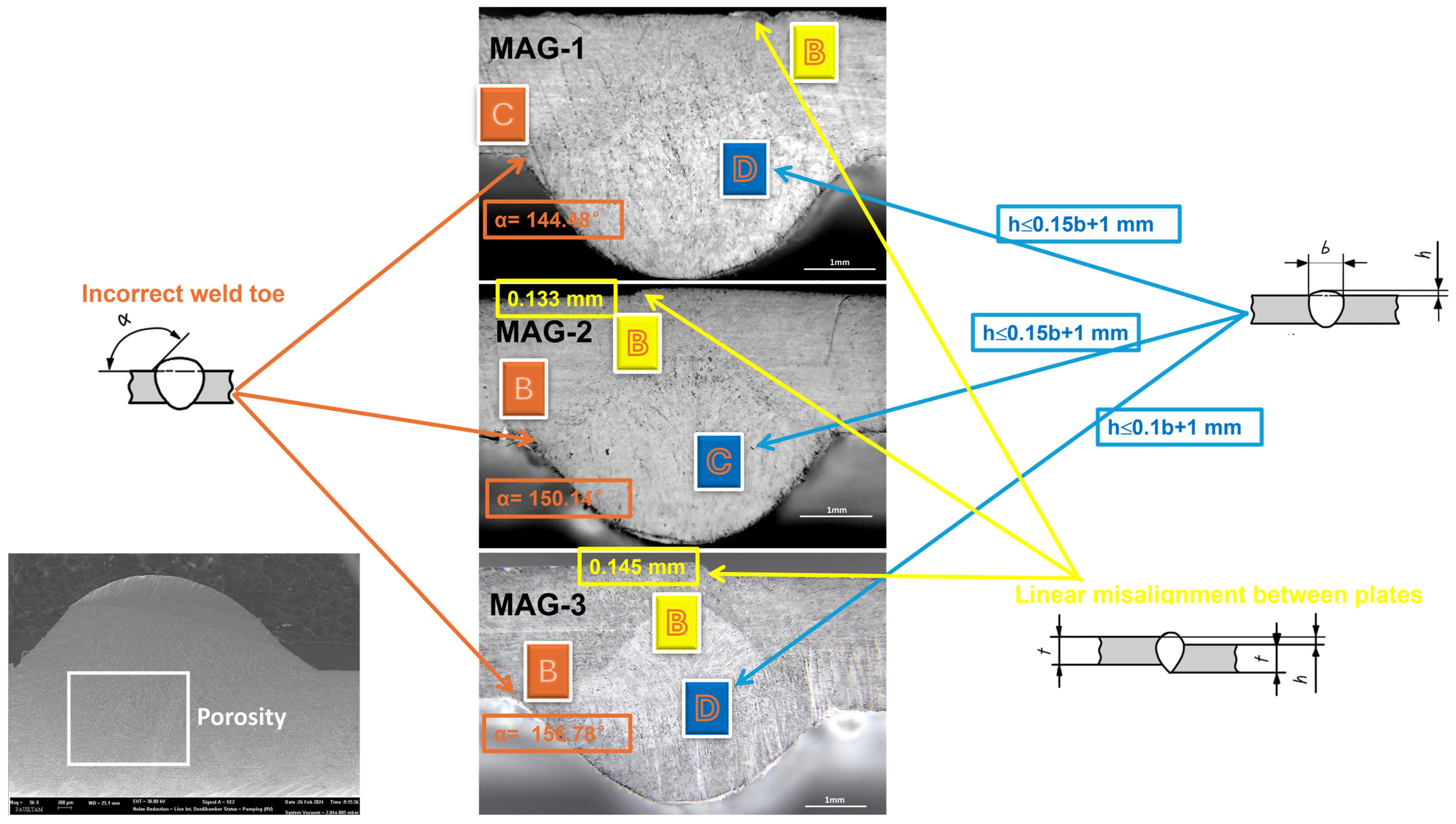
For butt welds, the incorrect weld toe angle values are given as α ≥ 90° for D grade, α ≥ 110° for C grade, and α ≥ 150° for B grade. The α values were obtained to be 144.48°, 150.14°, and 156.78° for MAG-1, MAG-2, and MAG-3 specimens, respectively. As a result of the evaluation, MAG-2 and MAG-3 were determined to be Class B, while MAG-1 was determined to be Class C.
For butt welds with excess weld metal imperfections, smooth transition is required between the capping run(s) and the plate surface and/or the adjacent welding bead(s). For grade D, h ≤ 0.25 b + 1 mm (but max. 10 mm), for grade C, h ≤ 0.15 b + 1 mm (but max. 7 mm), and for grade B, h ≤ 0.1 b + 1 mm (but max. 5 mm) must be met. The b and h values were found to be 4.85 and 1.8 mm for MAG-1, 4.3 and 1.54 mm for MAG-2, and 5.16 and 1.58 mm for MAG-3 specimens. As a result of the evaluation, MAG-1 and MAG-3 were determined to be class D, while MAG-2 was determined to be class C.
Butt welding criteria for determining linear misalignment between plate imperfections for plates under 3 mm are as follows: For D grade, h ≤ 0.25 t + 0.2 mm; For C grade, h ≤ 0.15 t + 0.2 mm; for B grade, h ≤ 0.1 t + 0.2 mm. t represents the plate thickness and h represents the plate displacement. This imperfection type has not formed for the MAG-1 sample. For MAG-2 and MAG-3, the h values were found to be 0.133 and 0.145 mm, respectively. Since h ≤ 0.4 mm is required for B grade, all samples were classified as B grade for this imperfection.
According to the porosity assessment given in Annex A of BS EN ISO 13919-1:2019, the porosity surface percentage in the MAG remains below 2%, and the welds are therefore acceptable as Class B in this respect.
The classification of MAG-1, MAG-2, and MAG-3 specimens based on the observed quality levels is revealed by the examination of weld imperfections such as the weld toe angle, linear misalignment, and excess weld metal, as seen in Figure 10. According to ISO 5817:2023(E), the overall quality level of a weld is governed by the most restrictive imperfection; therefore, the lowest quality class determined among the evaluated parameters was considered representative. No defects that primarily affect the strength of the weld, such as undercut, were detected. MAG-2 and MAG-3 satisfied Class B requirements with respect to the incorrect weld toe angle; however, lower quality levels were assigned for excess weld metal imperfections. MAG-1 was classified as Class C due to the weld toe angle. For excessive weld metal, MAG-1 and MAG-3 were classified as Class D, while MAG-2 was classified as Class C. For linear misalignment defects, all samples met the Class B requirements. These findings emphasize that a weld must meet the specified defect criteria to be considered successful. Compliance with these criteria is crucial in determining the overall quality classification of the weld. Since the imperfections did not exceed the limits specified in the standard and the specified criteria were met, the weld can be considered successful.
Figure 10.
Evaluation of weld imperfections in MAG-welded specimens. The classification results for each specimen (Class C, B, or D) are linked to the observed imperfections, including incorrect weld toe angles (orange), linear misalignment (blue), weld bead dimensions (yellow), and porosity (white).
As the HI increased (from 0.096 kJ/mm to 0.150 kJ/mm) in MAG welding, changes were observed in the geometric characteristics of the welds. No undercut defects were detected in any MAG condition, and all specimens satisfied the acceptance criteria defined by ISO 5817:2023(E) for the evaluated imperfections. However, higher HI values were also associated with increased excess weld metal and the development of coarser microstructures within the HAZ. These findings indicate that HI influences both weld geometry and microstructural evolution and should therefore be carefully controlled to achieve the desired weld quality.
3.3.2. Evaluation of ML and RL Welding Results
The analysis of the welded joints obtained by the ML and RL methods were performed in accordance with BS EN ISO 13919-1:2019 (Electron and laser-beam welded joints—Requirements and recommendations on quality levels for imperfections. Part 1: Steel, nickel, titanium and their alloys). Requirements and suggestions on the degree of defects in electron and laser-beam welded joints in steel, nickel, titanium, and their alloys are provided in this standard. In order to enable the use of a variety of welded fabrications, three levels are provided: B, C, and D. The highest standards for the final weld are associated with quality level B. The levels pertain to manufacturing quality rather than the created product’s suitability for its intended use. According to the standard, the following defects based on only weld geometry are considered in weld analyses: Lack of fusion, undercut, porosity, cracks, inclusions, overlap, excessive spatter, root concavity, misalignment, excess weld metal, and inadequate penetration (Figure 11).
Figure 11.
Schematic illustrations of welding imperfections adapted from BS EN ISO 13919-1:2019 [33].
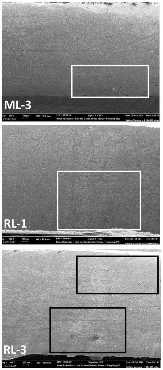
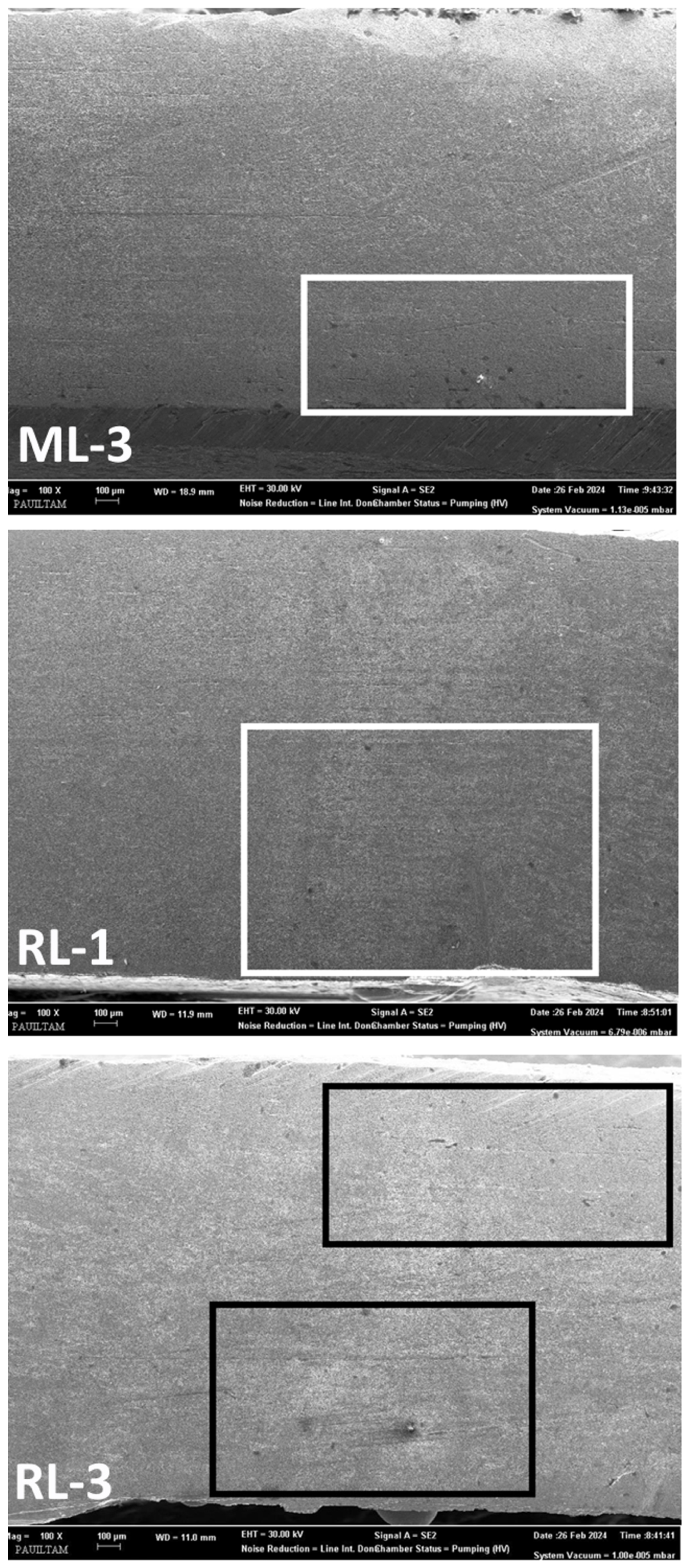
The welded joints exhibited proper fusion with no visible undercuts in the ML and RL-welded samples. Furthermore, there were no defects such as lack of fusion, root concavity, shrinkage groove, excess weld metal, excessive penetration, or lack of side wall fusion as specified in BS EN ISO 13919-1:2019 (Figure 10). In this sense, both ML and RL welds satisfy the requirements of quality level B. According to the porosity assessment and the acceptance requirements met, as given in Annex A of BS EN ISO 13919-1:2019, the porosity surface percentage in the ML and RL samples remains below 2%, and the welds are therefore acceptable as Class B in this respect. Different areas marked with porosity in the ML-3, RL-1, and RL-3 samples are shown in Figure 12.
Figure 12.
The specified sections for the porosity assessment of the ML-3, RL-1, and RL-3 samples according to BS EN ISO 13919-1:2019—Annex A.
Weld imperfections such as undercut, overlap, and lack of fusion are generally recognized as local stress concentrators that may reduce the effective load-bearing area and promote premature crack initiation during tensile loading. Since these imperfections were not detected in the present ML and RL welds, they were not considered to have contributed significantly to the measured tensile behavior. Consequently, the differences observed in the mechanical properties are more likely associated with variations in heat input, porosity distribution, and the resulting microstructural evolution. For clarity, the weld quality assessment results for all welding methods are summarized in Table 6, based on the evaluated imperfections and the corresponding acceptance criteria specified in ISO 5817:2023(E) and BS EN ISO 13919-1:2019.
Table 6.
Summary of weld quality classifications for all welding methods based on the evaluated weld imperfections in accordance with ISO 5817:2023(E) and BS EN ISO 13919-1:2019.
4. Conclusions
In the industrial production line of the collaborating manufacturing facility, HC420LA steel components are currently welded under predefined heat input (HI) conditions. Weld discontinuities were found in preliminary assessments conducted under these facility-specific welding settings, especially in laser-welded joints operated at rather high HI levels. Therefore, rather than suggesting universal or laboratory-optimized welding settings, the current investigation was driven by the need to reevaluate and refine the HI conditions utilized in this particular production scenario.
This study combined mechanical testing, hardness mapping, SEM/EDS/XRD characterization, and ISO-based weld quality assessment to compare the effects of manual laser (ML), robotic laser (RL), and MAG welding of 2 mm-thick HC420LA HSLA steel under various HI circumstances. Through their effects on defect generation, fusion stability, and the microstructural evolution of the fusion zone (FZ) and heat-affected zone (HAZ), the results show that welding procedure and HI mutually determine weld integrity. In particular, the findings demonstrate that variations in heat input significantly influence phase transformation behaviour and microstructural heterogeneity within the FZ and HAZ, which in turn govern the mechanical response of the welded joints.
With tensile strength and ductility values closest to those of the base material, particularly at the lowest HI level (0.108 kJ/mm), RL welding provided the best overall mechanical performance among the investigated joining methods. Although the RL specimens exhibited slightly lower ultimate tensile strength and elongation than the unwelded base material, fracture consistently occurred in the base metal rather than in the weld region, demonstrating that the welded joint was not the weakest section of the assembly. This observation indicates that the measured tensile properties reflect the global mechanical response of the heterogeneous welded joint rather than solely the local properties at the fracture location. Together with the balanced hardness distribution, high weld quality, and the stable microstructural and phase evolution confirmed by SEM, XRD, and EDS analyses, these findings demonstrate the high integrity and reliability of the RL joints.
On the other hand, under all HI circumstances, ML welds showed a noticeable loss of ductility and weld-metal fracture. The ML joints retained high FZ hardness and steep hardness gradients, which are consistent with the development of hard/brittle transformation products and decreased plastic deformability, even though increased HI enhanced surface appearance and decreased visible discontinuities in ML welds. These findings suggest that the rapid thermal cycles associated with ML welding promote the development of a harder weld microstructure, resulting in reduced ductility despite the improved geometric weld quality.
MAG welding demonstrated a non-linear dependence on HI: the MAG group’s highest tensile strength was produced by the intermediate HI condition (0.112 kJ/mm), while the excessive HI condition (0.150 kJ/mm) caused a significant decline in both strength and elongation, which was consistent with increased thermal exposure and microstructural coarsening effects. The observed degradation at higher HI levels is attributed to grain coarsening in the HAZ and the development of greater microstructural heterogeneity, which negatively affects mechanical performance.
The ISO 5817:2023(E) examination also revealed that the most restrictive flaw controls MAG weld quality; extra weld metal limited the overall quality level for certain situations, but weld toe angle and plate misalignment satisfied greater quality standards. The BS EN ISO 13919-1:2019 assessment for laser-based procedures verified that porosity levels stayed below the 2% threshold and that ML and RL welds fulfilled quality level B with regard to the assessed geometric flaws. The overall quality classifications obtained for all welding conditions provide a concise comparison of the weld integrity achieved by the three joining processes.
Overall, the results highlight that process stability, energy delivery characteristics, and thermal gradient control play critical roles in defect susceptibility and microstructure–property relationships; matching HI alone is not sufficient to guarantee equivalent weld performance across different joining technologies. The combined SEM, EDS, XRD, mechanical, and weld quality analyses demonstrate that reliable assessment of welded joints requires an integrated evaluation of microstructural evolution, phase constitution, elemental distribution, and mechanical behaviour.
The best method for creating mechanically sound and ISO-compliant joints in HC420LA within the examined parameter window was RL welding at low HI; MAG welding needs to be carefully optimized to prevent excess weld metal and thermal degradation at high HI; and ML welding gains from better process control to increase ductility and reduce weld-zone fracture.
The results of this study offer a framework for future welding parameter optimization in production conditions unique to individual facilities. Future work should focus on linking real-time process control with microstructural evolution and phase transformation mechanisms through advanced local characterization techniques to further improve weld performance and reliability.
Author Contributions
Conceptualization, C.K. and A.I.; methodology, C.K. and A.I.; formal analysis, A.I.; investigation, C.K.; resources, C.K. and A.I.; writing—original draft preparation, A.I.; writing—review and editing, C.K. and A.I.; supervision, A.I. All authors have read and agreed to the published version of the manuscript.
Funding
This research received no external funding.
Data Availability Statement
The original contributions presented in this study are included in the article. Further inquiries can be directed to the corresponding author.
Acknowledgments
All data in this study were obtained from the master science thesis entitled “Investigation of the mechanical and metallurgical properties of welded joints of HC420LA steel sheet with laser (RLW) and gas metal arc welding (MAG) techniques”, completed by Cemil Kobak under the supervision of Arzum Işıtan [61]. One part of this study was presented as an oral presentation at the KSME Annual Meeting 2024 International Session, held in Jeju, Korea, and online from 6 November (Wednesday) to 9 November (Saturday), 2024 [62]. The authors would like to thank Askon Demir Çelik for providing materials and welding machines as well as other equipment. The authors have reviewed and edited the output and take full responsibility for the content of this publication.
Conflicts of Interest
Author Cemil Kobak was employed by the company Askon Demir Çelik, author Arzum Işıtan was employed by the company Bilgece Mühendislik Geri Dönüşüm Ltd. The authors declared that the research was conducted in the absence of any commercial or financial relationships that could be construed as a potential conflict of interest.
References
- Rodionova, I.G.; Amezhnov, A.V.; Kudashov, D.V.; Naumenko, V.V.; D’yakonov, D.L.; Stukalova, N.A.; Arutyunyan, N.A. Effect of Heat Treatment in Pipe Processing Stage on Corrosion Resistance of Micro-Alloyed Steel Hot-Rolled Products. Metallurgist 2020, 64, 322–333. [Google Scholar] [CrossRef] [Scilit]
- Wang, Y.; Feng, A.; Pan, X.; Chen, C.; Wei, Y.; Wang, J. Study on the Microstructure and Properties of Welded Joints of Laser Shock Peening on HC420LA Low-Alloy High-Tensile Steel. Materials 2023, 16, 4238. [Google Scholar] [CrossRef] [Scilit] [PubMed]
- Xie, Z.; Song, Z.; Chen, K.; Jiang, M.; Tao, Y.; Wang, X.; Shang, C. Study of Nanometer-Sized Precipitation and Properties of Fire Resistant Hot-Rolled Steel. Metals 2019, 9, 1230. [Google Scholar] [CrossRef] [Scilit]
- Li, Z.; Jia, P.; Liu, Y.; Qi, H. Carbide Precipitation, Dissolution, and Coarsening in G18CrMo2-6 Steel. Metals 2019, 9, 916. [Google Scholar] [CrossRef] [Scilit]
- Dzioba, I.; Pala, R. Strength and Fracture Toughness of Hardox-400 Steel. Metals 2019, 9, 508. [Google Scholar] [CrossRef] [Scilit]
- Gáspár, M. Effect of Welding Heat Input on Simulated Haz Areas in S960ql High Strength Steel. Metals 2019, 9, 1226. [Google Scholar] [CrossRef] [Scilit]
- Dong, H.; Hao, X.; Deng, D. Effect of Welding Heat Input on Microstructure and Mechanical Properties of HSLA Steel Joint. Metallogr. Microstruct. Anal. 2014, 3, 138–146. [Google Scholar] [CrossRef] [Scilit]
- Andrade, D.G.; Leitão, C.; Rodrigues, D.M. Influence of Base Material Characteristics and Process Parameters on Frictional Heat Generation during Friction Stir Spot Welding of Steels. J. Manuf. Process. 2019, 43, 98–104. [Google Scholar] [CrossRef] [Scilit]
- Mandal, N.R. Welding Defects. In Ship Construction and Welding; Springer: Singapore, 2017; Volume 2, pp. 283–292. ISBN 978-981-10-2955-4. [Google Scholar]
- Madhvacharyula, A.S.; Pavan, A.V.S.; Gorthi, S.; Chitral, S.; Venkaiah, N.; Kiran, D.V. In Situ Detection of Welding Defects: A Review. Weld. World 2022, 66, 611–628. [Google Scholar] [CrossRef] [Scilit]
- Atabaki, M.; Yazdian, N.; Kovacevic, R. Hybrid Laser/Arc Welding of Thick High-Strength Steel in Different Configurations. Adv. Manuf. 2018, 6, 176–188. [Google Scholar] [CrossRef] [Scilit]
- Liu, P.; Lu, F.; Liu, X.; Ji, H.; Gao, Y. Study on Fatigue Property and Microstructure Characteristics of Welded Nuclear Power Rotor with Heavy Section. J. Alloys Compd. 2014, 584, 430–437. [Google Scholar] [CrossRef] [Scilit]
- Hobart Brothers. Tips for Achieving Success When Welding High-Strength Low-Alloy Steels. Available online: https://www.hobartbrothers.com/resources/technical-articles/tips-for-achieving-success-when-welding-high-strength-low-alloy-steels/ (accessed on 4 July 2024).
- Khan, M.S.; Soleimani, M.; Midawi, A.R.H.; Aderibigbe, I.; Zhou, Y.N.; Biro, E. A Review on Heat Affected Zone Softening of Dual-Phase Steels during Laser Welding. J. Manuf. Process. 2023, 102, 663–684. [Google Scholar] [CrossRef] [Scilit]
- Zhang, S.; Sun, J.; Zhu, M.; Zhang, L.; Nie, P.; Li, Z. Fiber Laser Welding of HSLA Steel by Autogenous Laser Welding and Autogenous Laser Welding with Cold Wire Methods. J. Mater. Process. Technol. 2020, 275, 116353. [Google Scholar] [CrossRef] [Scilit]
- Xu, W.; Westerbaan, D.; Nayak, S.S.; Chen, D.L.; Goodwin, F.; Biro, E.; Zhou, Y. Microstructure and Fatigue Performance of Single and Multiple Linear Fiber Laser Welded DP980 Dual-Phase Steel. Mater. Sci. Eng. A 2012, 553, 51–58. [Google Scholar] [CrossRef] [Scilit]
- Dupont, J.; Marder, A. Thermal Efficiency of Arc Welding Processes. Weld. J. 1995, 74, 406–416. [Google Scholar]
- Funderburk, R. A Look at Input. Weld. Innov. 1999, 16, 359. [Google Scholar]
- Francis, J.A.; Holtum, N.; Olschok, S.; Roy, M.J.; Vasileiou, A.N.; Jakobs, S.; Reisgen, U.; Smith, M.C. Vacuum Laser Welding of SA508 Steel. J. Mater. Process. Technol. 2019, 274, 116269. [Google Scholar] [CrossRef] [Scilit]
- Robertson, S.M.; Frostevarg, J.; Ramasamy, A.; Kalfsbeek, B.; Volpp, J.; Kaplan, A.F.H. Microstructures of High-Strength Steel Welding Consumables from Directed Thermal Cycles by Shaped Laser Pulses. Int. J. Adv. Manuf. Technol. 2020, 109, 2653–2662. [Google Scholar] [CrossRef] [Scilit]
- Kopas, P.; Sága, M.; Jambor, M.; Nový, F.; Trško, L.; Jakubovičová, L. Comparison of the Mechanical Properties and Microstructural Evolution in the HAZ of HSLA DOMEX 700MC Welded by Gas Metal Arc Welding and Electron Beam Welding. MATEC Web Conf. 2018, 244, 01009. [Google Scholar] [CrossRef] [Scilit]
- Kurc-Lisiecka, A.; Lisiecki, A. Laser Welding of the New Grade of Advanced High-Strength Steel Domex 960. Mater. Tehnol. 2017, 51, 199–204. [Google Scholar] [CrossRef] [Scilit]
- Panchenko, O.; Kladov, I.; Kurushkin, D.; Zhabrev, L.; Ryl’kov, E.; Zamozdra, M. Effect of Thermal History on Microstructure Evolution and Mechanical Properties in Wire Arc Additive Manufacturing of HSLA Steel Functionally Graded Components. Mater. Sci. Eng. A 2022, 851, 143569. [Google Scholar] [CrossRef] [Scilit]
- Kumari, N.; Kanishka, K.; Acherjee, B. Investigation of Anisotropy in Wire Arc Additively Manufactured HSLA Steel: Microstructural, Mechanical, and Corrosion Analysis. Structures 2025, 81, 110184. [Google Scholar] [CrossRef] [Scilit]
- Ghazali, S.N.M.; Ibrahim, M.H.I.; Manurung, Y.H.P.; Adenan, M.S.; Rahman, A.R.A.; Ramlan, A.R.; Harati, E.; Busari, Y.O. A Focused Review on Numerical Computation in Wire Arc Additive Manufacturing for High Strength Low Alloy Steels: Past Insights and Potential Opportunities. Int. J. Adv. Manuf. Technol. 2025, 141, 2679–2708. [Google Scholar] [CrossRef] [Scilit]
- DIN EN 10268:2013-12; Cold Rolled Steel Flat Products with High Yield Strength for Cold Forming—Technical Delivery Conditions. DIN Media GmbH: Berlin, Germany, 2013.
- Skobir, D.A. High-Strength Low-Alloy (HSLA) Steels. Mater. Tehnol. 2011, 45, 295–301. [Google Scholar]
- Cui, J.; Wang, Q.; Dong, D.; Jiang, H.; Zhang, X.; Li, G. A Study on the Constitutive Equation of HC420LA Steel Subjected to High Strain Rates. J. Mater. Res. 2019, 34, 1034–1042. [Google Scholar] [CrossRef] [Scilit]
- Miháliková, M.; Német, M.; Vojtko, M. Impact of Strain Rate on Microalloyed Steel Sheet Fracturing. Acta Polytech. 2014, 54, 281–284. [Google Scholar] [CrossRef] [Scilit]
- Li, W.; Feng, A.; Wang, Y.; Wang, J. Effect of Laser Welding Parameters on the Microstructure and Tensile Properties of Low-Alloy High-Strength Steel. Mater. Res. Express 2024, 11, 096526. [Google Scholar] [CrossRef] [Scilit]
- Stano, S.; Grajcar, A.; Wilk, Z.; Różański, M.; Matter, P.; Morawiec, M. Microstructural Aspects of Twin-Spot Laser Welding of DP-HSLA Steel Sheet Joints. Arch. Metall. Mater. 2016, 61, 731–740. [Google Scholar] [CrossRef] [Scilit]
- ISO 5817:2023; Welding—Fusion-Welded Joints in Steel, Nickel, Titanium and Their Alloys (Beam Welding Excluded)—Quality Levels for Imperfections. International Organization for Standardization (ISO): Geneva, Switzerland, 2023.
- ISO 13919-1:2019; Electron and Laser-Beam Welded Joints—Requirements and Recommendations on Quality Levels for Imperfections—Part 1: Steel, Nickel, Titanium and Their Alloys. International Organization for Standardization (ISO): Geneva, Switzerland, 2019.
- Oyak Maden Metalurji. Cold Rolled Products. Available online: https://katalog.oyakmadenmetalurji.com.tr/brosurler (accessed on 20 February 2025).
- ISO 9692-1:2013; Welding and Allied Processes—Types of Joint Preparation—Part 1: Manual Metal Arc Welding, Gas-Shielded Metal Arc Welding, Gas Welding, TIG Welding and Beam Welding of Steels. International Organization for Standardization (ISO): Geneva, Switzerland, 2013.
- Fronius. TPS 500i. Available online: https://www.fronius.com/en/welding-technology/products/manual-welding/migmag/tpsi/tpsi/tps-500i (accessed on 4 July 2024).
- ISO 14341:2020; Welding Consumables—Wire Electrodes and Weld Deposits for Gas Shielded Metal Arc Welding of Non Alloy and Fine Grain Steels—Classification. International Organization for Standardization (ISO): Geneva, Switzerland, 2020.
- Magmaweld. MG 2. Available online: https://www.magmaweld.com.tr/mg-2-uo (accessed on 4 July 2024).
- Lasersonic. Laser Welding Systems. Available online: https://pmtgep.hu/wp-content/uploads/2023/09/Lasersonic-katalogus-2.pdf (accessed on 6 July 2024).
- TWI. Handheld Laser Welding—What to Consider. Available online: https://www.twi-global.com/media-and-events/press-releases/2023/handheld-laser-welding-what-to-consider (accessed on 4 July 2024).
- Kuntai Laser. Advantages and Disadvantages of Handheld Laser Welding Machines. Available online: https://www.kuntailaser.com/advantages-and-disadvantages-of-handheld-laser-welding-machines/ (accessed on 13 July 2026).
- DenaliWeld. 5 Reasons to Use Handheld Laser Welders. Available online: https://denaliweld.com/blog/reasons-to-use-handheld-laser-welders/ (accessed on 4 July 2024).
- CorActive CFLS Series of High-Power CW Fiber Lasers. Available online: https://f.nordiskemedier.dk/25axcfrrm4geg28a.pdf (accessed on 6 July 2024).
- Pekkarinen, J.; Kujanpää, V. The Effects of Laser Welding Parameters on the Microstructure of Ferritic and Duplex Stainless Steels Welds. Phys. Procedia 2010, 5, 517–523. [Google Scholar] [CrossRef] [Scilit]
- Lahtinen, T.; Vilaça, P.; Peura, P.; Mehtonen, S. MAG Welding Tests of Modern High Strength Steels with Minimum Yield Strength of 700 MPa. Appl. Sci. 2019, 9, 1031. [Google Scholar] [CrossRef] [Scilit]
- SIST EN ISO 6892-1:2020; Metallic Materials—Tensile Testing—Part 1: Method of Test at Room Temperature. Slovenian Institute for Standardization (SIST): Ljubljana, Slovenia, 2020. Available online: https://standards.iteh.ai/catalog/standards/sist/cd387b12-7788-4409-88ce-5f369e874358/sist-en-iso-6892-1-2020 (accessed on 25 May 2026).
- ISO 9013:2017(en); Thermal Cutting—Classification of Thermal Cuts—Geometrical Product Specification and Quality Tolerances. International Organization for Standardization (ISO): Geneva, Switzerland, 2017. Available online: https://www.iso.org/obp/ui/es/#iso:std:iso:9013:ed-3:v1:en (accessed on 25 May 2026).
- ISO 6507-1:2023; Metallic Materials—Vickers Hardness Test—Part 1: Test Method. International Organization for Standardization (ISO): Geneva, Switzerland, 2023. Available online: https://www.iso.org/standard/83898.html (accessed on 25 May 2026).
- Mičian, M.; Frátrik, M.; Brůna, M. Softening Effect in the Heat-Affected Zone of Laser-Welded Joints of High-Strength Low-Alloyed Steels. Weld. World 2024, 68, 1497–1514. [Google Scholar] [CrossRef] [Scilit]
- Mansur, V.M.; de Figueiredo Mansur, R.A.; de Carvalho, S.M.; de Siqueira, R.H.M.; de Lima, M.S.F. Effect of Laser Welding on Microstructure and Mechanical Behaviour of Dual Phase 600 Steel Sheets. Heliyon 2021, 7, e08601. [Google Scholar] [CrossRef] [Scilit] [PubMed]
- Moorthy, S.B.; Malayalamurthy, R.; Amirthagadeswaran, K.S. Experimental Study on MAG Welded E350 HSLA Steel Joints. Mater. Technol. 2024, 58, 209–215–209–215. [Google Scholar] [CrossRef] [Scilit]
- Riofrío, P.G.; Capela, C.A.; Ferreira, J.A.M.; Ramalho, A. Interactions of the Process Parameters and Mechanical Properties of Laser Butt Welds in Thin High Strength Low Alloy Steel Plates. Proc. Inst. Mech. Eng. Part L J. Mater. Des. Appl. 2020, 234, 665–680. [Google Scholar] [CrossRef] [Scilit]
- John, M.; Kumar, P. Effect of Wire Feed Rate on Microstructure Development during Bead on Plate Welding of Microalloyed Steel Using P-GMAW. Mater. Today Proc. 2021, 42, 423–428. [Google Scholar] [CrossRef] [Scilit]
- Alipooramirabad, H.; Ghomashchi, R.; Paradowska, A.; Reid, M. Residual Stress- Microstructure- Mechanical Property Interrelationships in Multipass HSLA Steel Welds. J. Mater. Process. Technol. 2016, 231, 456–467. [Google Scholar] [CrossRef] [Scilit]
- Meirinho, L.C.G. Sustainable Joining of Steels for the Automotive Industry; Universidade de Coimbra: Coimbra, Portugal, 2023. [Google Scholar]
- Özdemir, Y.; Demir, B.; Ahlatcı, H.; Sun, Y.; Yaşar, M. The Cryogenic Treatment of the Laser Weld Junctions of Automotive Steel. Karabuk Univ. J. Steel Res. Dev. 2023, 4, 24–30. [Google Scholar]
- Beknalkar, S.A.; Teli, A.M.; Bhat, T.S.; Pawar, K.K.; Patil, S.S.; Harale, N.S.; Shin, J.C.; Patil, P.S. Mn3O4 Based Materials for Electrochemical Supercapacitors: Basic Principles, Charge Storage Mechanism, Progress, and Perspectives. J. Mater. Sci. Technol. 2022, 130, 227–248. [Google Scholar] [CrossRef] [Scilit]
- He, M.; Kang, H.; Lin, S.; Liu, Y.; Zhang, P.; Qin, W.; Wu, X. Impressive High-Temperature Oxidation Resistance of FeCrNiMnAl High Entropy Alloy Coating on the Ferritic/Martensitic Steel with Primordial Al2O3 and Mn3O4 Gradient Films. J. Alloys Compd. 2022, 928, 167109. [Google Scholar] [CrossRef] [Scilit]
- Kang, X.; Li, G.; Jiang, W.; Li, F.; Wang, Y.; Wang, X.; Zeng, Q.; Fan, X. Wire-Based Additive Manufacturing of Multi-Material Structures: A Review. J. Compos. Sci. 2025, 9, 534. [Google Scholar] [CrossRef] [Scilit]
- Fonseca, P.P.; Duarte, V.R.; Farias, F.W.C.; Cota, B.S.; Silva, T.; Santos, T.G.; Machado, C.M. Enhancing Manufacturing and Post-Processing Properties of WAAM ER110 HSLA Steel: In Situ Hot Forging + Post-Deposited Heat Treatment Effects on Surface Quality and Specific Cutting Energy. Prog. Addit. Manuf. 2025, 10, 3417–3436. [Google Scholar] [CrossRef] [Scilit]
- Kobak, C. Investigation of the Mechanical and Metallurgical Properties of Welded Joints of HC420LA Steel Sheet with Laser (RLW) and Gas Metal Arc Welding (MAG) Techniques. Master’s Thesis, Pamukkale University Institute of Natural Sciences, Denizli, Turkey, 2024. [Google Scholar]
- Kobak, C.; Işıtan, A. The Reduction of Welding Discontinuity and Imperfections in Laser Welding of HC420LA Steel Sheets. In Proceedings of the KSME Annual Meeting 2024 International Session; The Korean Society of Mechanical Engineers: Jeju, Republic of Korea, 2024; p. 1015. [Google Scholar]

Disclaimer/Publisher’s Note: The statements, opinions and data contained in all publications are solely those of the individual author(s) and contributor(s) and not of MDPI and/or the editor(s). MDPI and/or the editor(s) disclaim responsibility for any injury to people or property resulting from any ideas, methods, instructions or products referred to in the content. |
© 2026 by the authors. Licensee MDPI, Basel, Switzerland. This article is an open access article distributed under the terms and conditions of the Creative Commons Attribution (CC BY) license.