


Abstract
A piezoelectric (PZT) nanopositioning stage with large stroke and low crosstalk is relatively appealing for microdisplacement operation. Rhombus and lever amplifiers are used to increase the overall displacement amplification ratio (DAR), and the symmetry of the amplification structure reduces the coupling error. At the same time, decoupling beams are used to balance the stiffness in the x- and y-directions, thereby reducing the crosstalk of the stage. Theoretical analysis, kinematics modeling, and finite element simulation were carried out to verify the feasibility of the PZT nanopositioning stage, and an experimental prototype was manufactured. The prototype test results indicate that the workspace of the stage is 312 μm × 312 μm, the DAR is approximately 9.3, and the first natural frequency is approximately 76 Hz. Moreover, the area efficiency is 6.03, which indicates that the stage is compact. The results prove that the developed stage possesses a good property for microdisplacement operation.
1. Introduction
Compliant mechanisms based on flexible beams are widely used in various disciplines and industrial applications [1], including nanopositioning [2,3], micrograsping operation [4], and fast servo tools for precision manufacturing [5]. In these applications, large motion ranges, fast responses, and high-precision nanopositioning platforms are urgently required. In order to achieve a larger workspace, preliminary research has been conducted as follows.
Some common solutions include selecting a large-stroke actuator. Typically, due to its advantage of large stroke, a voice coil motor (VCM) is often used as the actuator [6]. Shang et al. presented a two-degree flexure-based micropositioning stage with a workspace of 1.8 mm × 1.78 mm. However, the VCM-actuated positioning stage could not realize positioning in nanoscale due to the low resolution of the VCM actuator [7].
Piezoelectric (PZT) actuators, which convert electrical energy into mechanical energy, are often used as actuators in compliant mechanisms due to their fast frequency response, nanoscale resolution, and compact structure, considering resolution. However, the strain of PZT actuators is typically only 0.1%. An appropriate displacement amplifier must be designed to increase the stroke of the PZT-actuated platform. Yong et al. proposed a compliant two-degrees-of-freedom (2-DOF) nanopositioning stage with lever displacement amplification, and the displacement amplification ratio (DAR) of the two axes was approximately 2.5, and the workspace was 10 μm × 10 μm with a high resolution of 39 nm [8]. Wang et al. designed a PZT-actuated compliant microgripper with multiple-lever amplifiers, and the DAR was 22.3 [9]. Tang et al. developed a piezo-actuated flexible 2-DOF micromanipulator with a millimeter workspace of 3.1273 mm × 26.5°, and the DAR was 31 [10]. Zhu et al. developed a piezo-actuated parallel mechanism with a bridge-type mechanism and two-stage leverage mechanisms for increasing the DAR as high as 35.68 [11]. However, with the increase in lever series and DAR, the dynamic performance of the flexible mechanism becomes worse for the recognized tradeoff between dynamic frequency and motion range in the design of flexible mechanisms, thereby greatly limiting their use for simultaneous large workspaces and fast dynamic responses.
Pokines et al. developed a micro-electro-mechanical system (MEMS) based on bridge-type micro amplification with a DAR of 5.48 [12], which can provide larger DAR with more compact mechanism dimension. Sohail et al. proposed an analysis method of MEMS-based displacement amplification mechanism and proved the relationship between structural parameters and DAR [13]. Xu et al. investigated a flexure-based compound bridge-type displacement amplifier for PZT drives; the DAR was 12.80, the initial natural frequency was 89.19 Hz, and the output displacement was over 1 mm [14].
Most high-precision positioning platforms have a small range of motion (<200 μm) [2,3,4,15]. The primary design motivation is to develop a compact nanopositioning platform with a motion range exceeding 300 μm and a maximized resonance frequency for atomic force microscopy applications [16].
A compact multi-displacement amplifier structure is designed by integrating a rhombus amplifier with a lever mechanism, thereby achieving a larger DAR. This configuration amplifies the PZT actuator’s output displacement, consequently extending the nanopositioning platform’s motion range. Moreover, a void-cut strategy is employed to eliminate unnecessary mass, which significantly elevates the natural frequency of the nanopositioning stage. Additionally, decoupling beams are incorporated to mitigate output crosstalk [15].
Piezoelectric materials exhibit significant nonlinear rate-dependent hysteresis behaviors that considerably degrade their positioning accuracy, especially under high-frequency excitations [17,18]. Rate-dependent hysteresis models, particularly differential-based approaches such as the Bouc–Wen and Dahl models, have been developed to characterize these behaviors. Ao et al. developed a dual-structure reinforced MXene/PVDF-TrFE piezoelectric nanocomposite that achieves significant enhancement in piezoelectric properties through the synergistic coupling of interfacial polarization and structural engineering. The remarkable improvement in piezoelectric current output—representing a threefold boost in piezoelectric response—offers a promising strategy for addressing the rate-dependent nonlinear hysteresis in piezoelectric stack actuators [19].
The remainder of this paper is organized as follows. Section 2 introduces the structure design and a pseudo-static model is applied to analyze the flexible mechanism. Section 3 uses the ANSYS Workbench 19.2 to verify the performance of the designed model. The proposed prototype is tested in Section 4, and finally, the conclusion is provided in Section 5.
2. Design and Kinematics Modeling
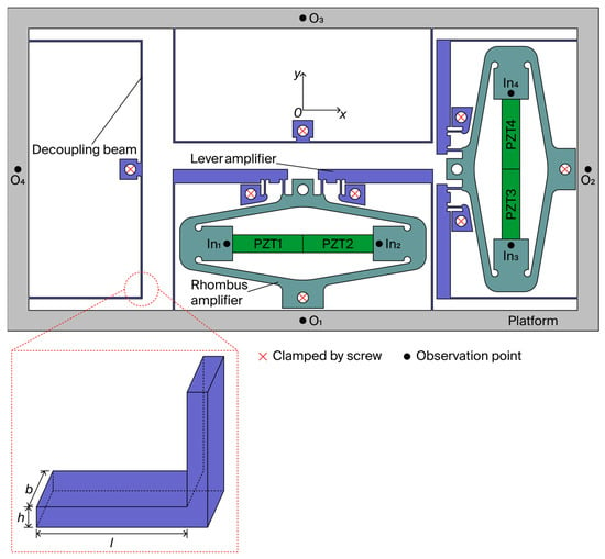
The design of the rhombus and lever amplifiers is shown in Figure 1. The rhombus amplifier offers the dual benefits of preloading the PZT actuator and providing displacement amplification, while its integration with a lever amplifier yields a compact architecture that further extends the stroke. Decoupling beams are incorporated to fully suppress crosstalk between the output displacements along the x- and y-axes.
Figure 1.
Proposed 2-DOF nanopositioning stage.
A pseudo-static model is adopted to describe concurrent kinematics and dynamics of the entire flexible mechanism [20]. Assuming linear elastic deformation, as illustrated in Figure 1, the mechanism is mainly composed of flexible beams. Evidently, different structures of flexible beams have different stiffness and bear different degrees of deformation. The compliance of the flexible beam is considered to improve the modeling accuracy.
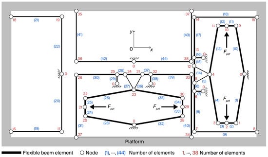
As illustrated in Figure 2, the proposed 2-DOF nanopositioning stage is simplified and represented as a series of flexible beams, indexed from (1) to (44). Nodes numbered 1 to 38 serve as connectors between adjacent beams, while all fixed nodes are designated as node 0. The PZT actuator’s output force is denoted as Fpzt. The input beam, which interfaces directly with the PZT actuator, is modeled as a flexible beam due to its compliance exerting a significant influence on the static and dynamic characteristics of the entire mechanism.
Figure 2.
Discretization and numbering of the entire mechanism.
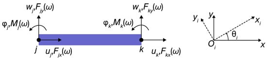
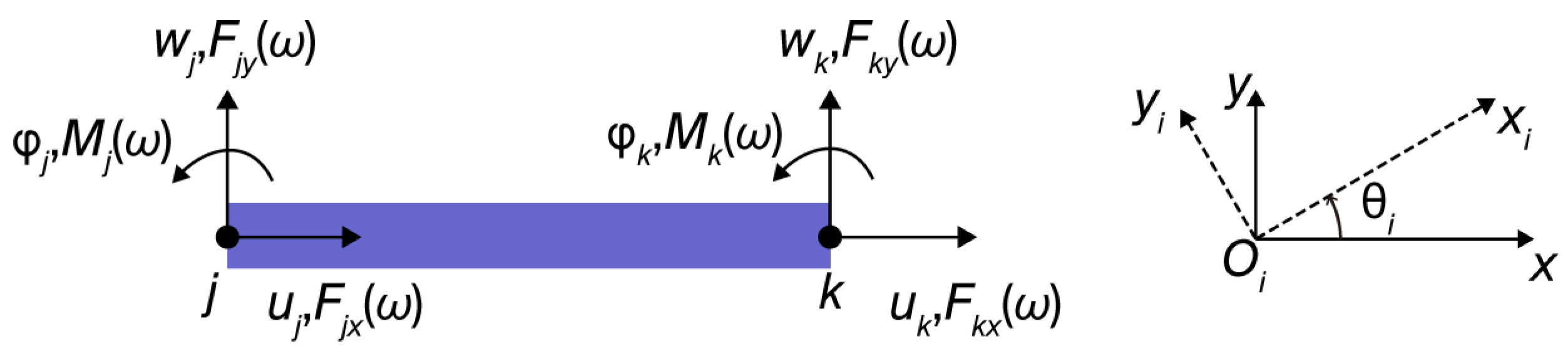
The flexible beam is idealized as simplified rod element with uniform cross-sectional geometry in Figure 3. In this discretized representation, each rod element is defined by a pair of terminal nodes, denoted as j and k. Within the local coordinate system, each node possesses three independent DOFs: axial displacements ( and ), transverse deflections ( and ), and rotations about the out-of-plane axis ( and ), corresponding to the forces at the node.
Figure 3.
Nodal displacement and nodal force of the flexible beam.
Prior to establishing the pseudo-static model of the entire mechanism, the dynamic stiffness matrix of the flexible beam, which characterizes the frequency-dependent nodal force–displacement relationship, is derived. The dynamic stiffness matrix of the flexible beam under the excitation frequency is expressed in Equation (1).
In which
where and . The parameter denotes the Young’s modulus, while represents the mass per unit length, and specifies the length of the flexible beam. The cross-sectional area and the second moment of area about the neutral axis are given by bh and bh3/12, respectively, where b and h correspond to the width and height of the beam’s cross-section, as illustrated in Figure 1.
Utilizing the dynamic stiffness matrix of the flexible beam expressed in Equation (1), the nodal force–displacement relationship of the flexible beam within the reference system can be articulated as follows:
Here, and denote the two nodal forces, while and represent the two nodal displacements, which are all defined within the reference coordinate system. [, ;,] is the dynamic stiffness matrix for the ith flexible beam, transformed from the local coordinate system via rotational transformation.
where the rotation matrix is defined based on the orientation of the ith flexible beam relative to the reference coordinate system, and is the angle from the global x-axis to the local xi-axis, as illustrated in Figure 3.
Considering each node (from 1 to 38) as the research object, the force applied on the node is the sum of the inverse nodal forces from its connected flexible beams and any external force. Consequently, for each node, the following force equilibrium equation can be derived for the nth node:
where N is the total count of flexible beams interfacing with the nth node. As illustrated in Figure 2, the nth node may be linked to the j-end or k-end of the ith flexible beam. Consequently, when the nth node is linked to the j-end, then is applicable; otherwise, becomes relevant. Pn represents the aggregate of external forces directly exerted on the nth node. For example, the output force of PZT actuator Fpzt is presumed to be directly applied to nodes 2, 10, 21, and 29.
Equation (3) is used to transform Equation (6) into the following:
Equation (7) represents the force equilibrium equation at the nth node. Taking node 21 in Figure 2 as an example,
Equilibrium equations for the remaining nodes can be derived analogously from Equation (7), and are therefore omitted for brevity. By referring to the equilibrium equations of all nodes in turn, the pseudo-static model of the flexible mechanism with node displacements as the primary variables can be constructed as follows:
where and . The dynamic stiffness matrix of half of the mechanism in the y-direction is as follows:
With a similar derivation procedure, the dynamic stiffness matrix in the x-direction can be obtained but is omitted here for the symmetry of the mechanism. By setting the dynamic frequency to 0, the DAR, A, in the y-direction can be calculated as follows:
where the variable corresponds to the output displacement along the y-direction, while corresponds to the input displacement, as illustrated in Figure 2.
3. Finite Element Analysis and Evaluation
The static performance and natural frequency were analyzed by ANSYS Workbench 19.2 to verify the feasibility of the designed model. The material of the mechanism was Al7075 [21] with Young’s modulus of 71.7 GPa, density of 2770 kg/m3, Poisson’s ratio of 0.33, and yield strength of 503 MPa.
3.1. Static Structural Analysis
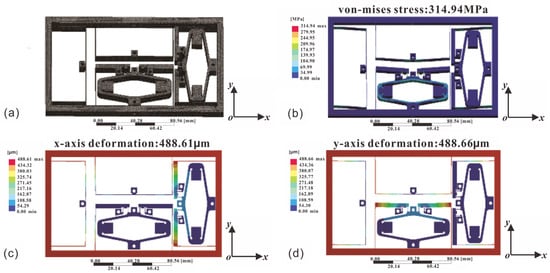
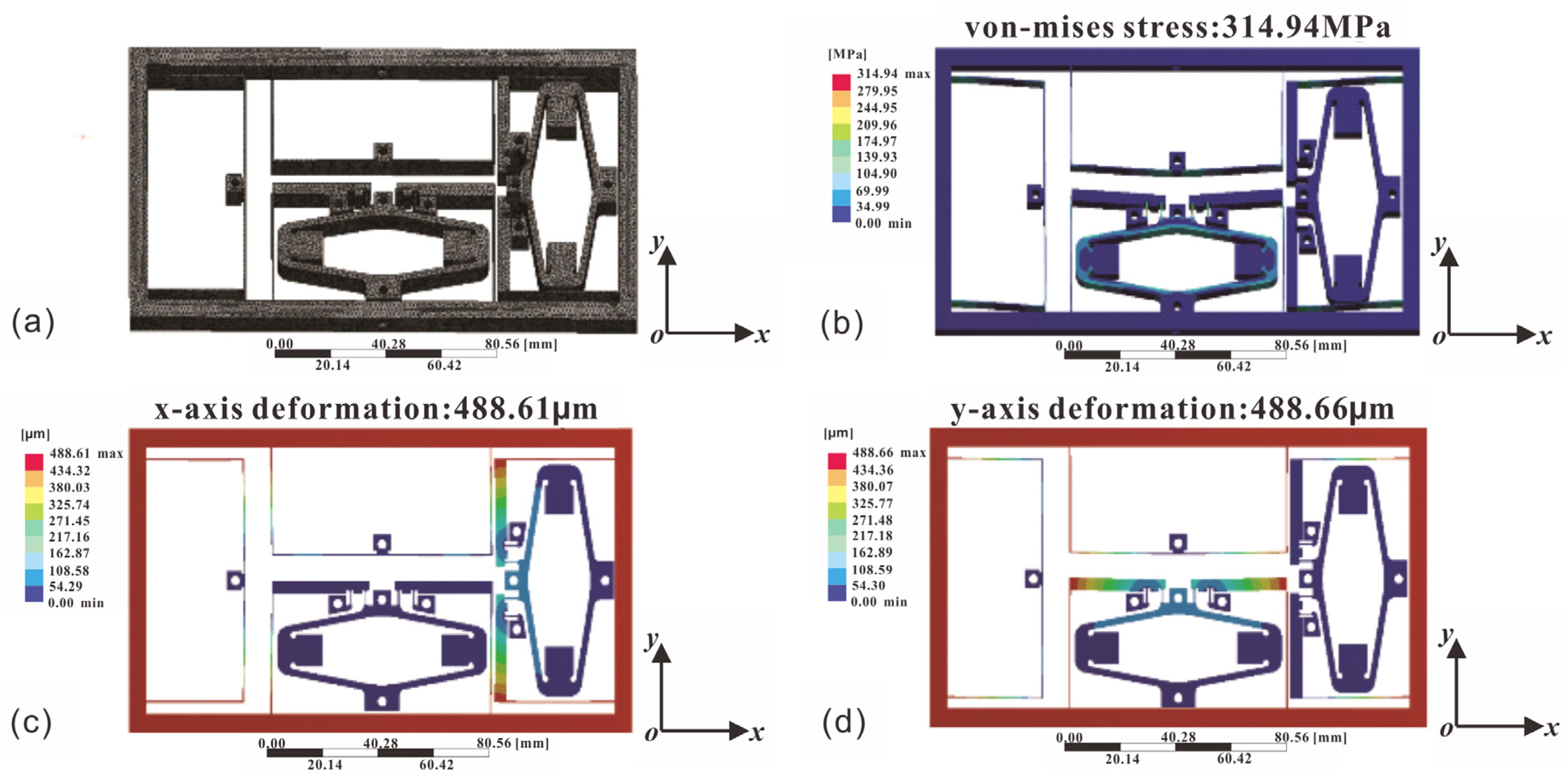
The three-dimensional FEA model was established as illustrated in Figure 4a.
Figure 4.
Finite Element Analysis (FEA) results for static structure analysis. (a) Three-dimensional FEA model, (b) von Mises stress distribution, (c) deformation along the x-axis, (d) deformation along the y-axis.
(1) To assess the amplification capability and decoupling performance of the modeled stage under an x-axis driving force, the input forces are applied at points In1 and In2. The subsequent deformation characteristics are quantified as follows: the ratio of do1y, do2y, do3y, and do4y captures the deformation relations at the respective points, while the sum of dIn1x and dIn2x denotes the relationship between the stage’s y-axis output displacement and the actuator’s output displacement. The parasitic movements at the output points are denoted by do1x, do2x, do3x, and do4x, and the y-axis output coupling error is defined as .
(2) In the same way, the input forces on points In3 and In4 are adopted to assess the effect of a y-axis driving force. The ratio of do1x, do2x, do3x, and do4x captures the deformation relations at the respective points along the x-axis, while the sum of dIn3y and dIn4y denotes the relationship between the stage’s x-axis output displacement and the actuator’s output displacement. The parasitic movements at the output points are denoted by do1y, do2y, do3y, and do4y, and the x-axis output coupling error is defined as .
Subsequently, a series of forces were applied to points In1 and In2 along the x-axis (Table 1) to assess the stage’s accuracy, followed by the application of an identical force set to points In3 and In4 along the y-axis, as detailed in Table 2. The results demonstrate that, with increasing actuation force, the displacements of all critical points exhibited a proportional increase, thereby confirming the linear relationship between the input force and the stage’s output displacement. When a driving force was applied to points In1 and In2 along the x-axis, the maximum deformation at the output of the stage occurred at point O1, with an average output coupling error of 0.336%. The y-axis displacement amplification ratio Ay of the stage was 14.18. Conversely, applying the force to points In3 and In4 along the y-axis resulted in the maximum deformation at point O2, with an average output coupling error of 0.24%. The observed discrepancy may be attributed to elastic deformation. The x-axis displacement amplification ratio Ax of the stage was determined to be 14.36.
Table 1.
Static structure analysis of data of x-axis output.
Table 2.
Static structure analysis of data of y-axis output.
Exerting 1600 N force on points In1 and In2 by simulating the maximum output force of piezoelectric actuator, as depicted in Figure 4b, indicates a peak von Mises stress of 314.94 MPa (well below the material’s yield strength of 503 MPa). The corresponding maximum deformations in the x- and y-axis are 488.61 µm and 488.66 µm, presented in Figure 4c,d, respectively.
3.2. Modal Analysis
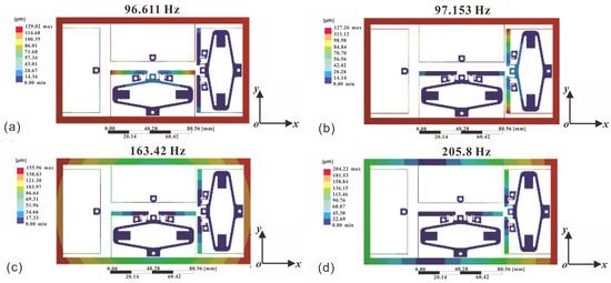
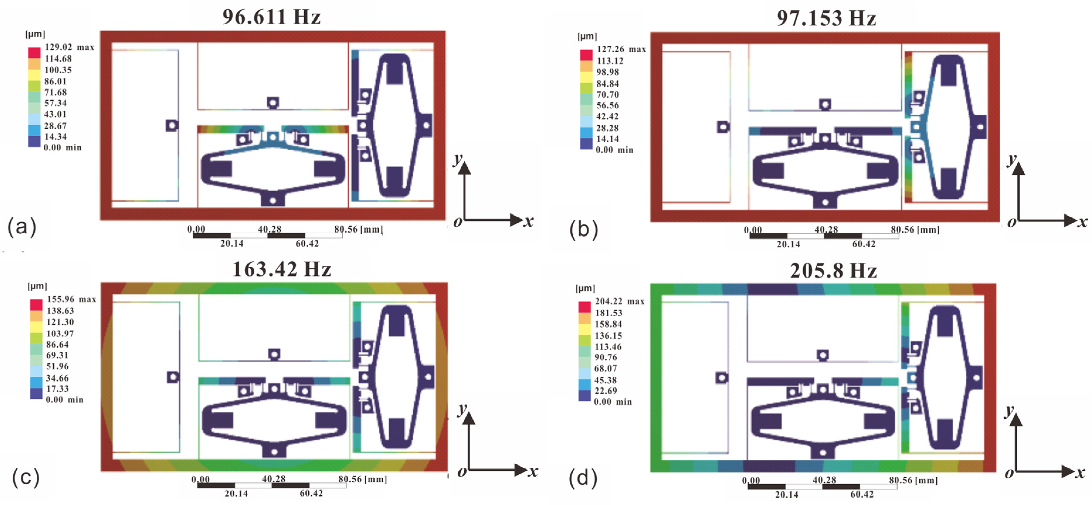
As illustrated in Figure 5, the deformation patterns associated with Modes 1 and 2 manifest along the y- and x-axes, respectively. Owing to the near-symmetrical nature of the structure, the deformation responses in the x- and y-directions are closely matched, resulting in adjacent resonance frequencies of 96.611 Hz and 97.153 Hz. Conversely, Modes 3 and 4 correspond to rotational and shear deformation, with resonance frequencies of 163.42 Hz and 205.8 Hz. Evidently, the x–y nanopositioning stage primarily operates under applied forces that induce deformation within the x–y plane. Consequently, the initial two natural frequencies of the stage are pivotal to the overall positioning performance.
Figure 5.
Results of modal analysis. (a) Mode 1: 96.611 Hz, (b) Mode 2: 97.153 Hz, (c) Mode 3: 163.42 Hz, (d) Mode 4: 205.8 Hz.
4. Experimental Implementation
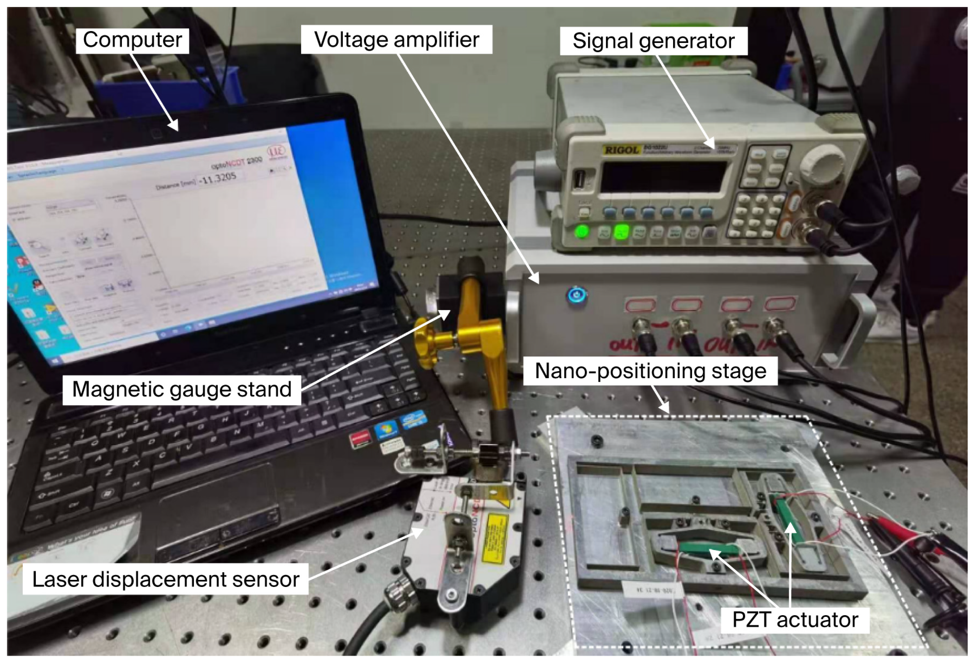
A specimen of AL7075-T651 alloy (Sichuan Jiuda New Material Technology Co., Ltd., Guangyuan, Sichuan, China) was selected for the fabrication of the experimental prototype utilizing the wire electrical discharge machining (WEDM) process. The comprehensive experimental setup is illustrated in Figure 6. The nanopositioning stage was driven by four PZT actuators (Pst150/5×5/20, Harbin, China) with d33 = +635 pm/V and maximum output force 1600 N, which were powered by a dual-channel voltage amplifier. Precise displacement measurements of the stage were acquired using a laser displacement sensor (LTS-025-04, MTI Instruments, Albany, NY, USA). To mitigate the influence of external disturbances, all equipment was mounted on a vibration isolation platform.
Figure 6.
Experimental setup of the proposed nanopositioning stage.
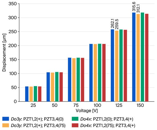
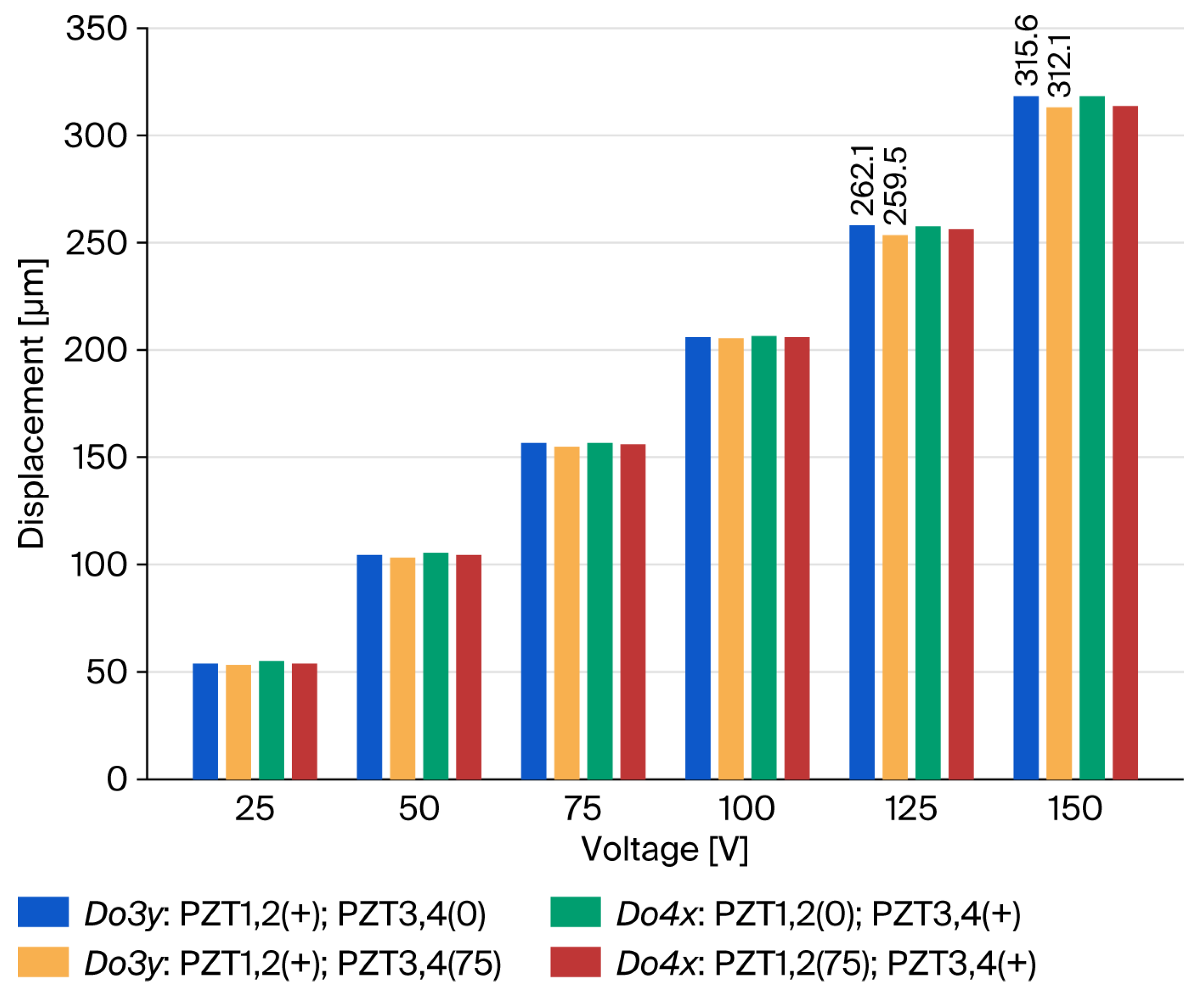
Several open-loop experiments were conducted. The preload on the PZT actuator was 500 N; a voltage sweep ranging from 0 to 150 V was sequentially applied to PZT1, PZT2, PZT3, and PZT4. The resultant displacement responses at points O3 and O4 were recorded at a constant sampling interval. Four distinct sets of experimental data were obtained and are presented in Figure 7. Do3y denotes the output displacement detected at O3 in the y-direction, and Do4x denotes the output displacement detected at O4 in the x-direction. (+) denotes the PZT actuated with changed voltage (0–150V), (0) denotes that PZT was not actuated, and (75) denotes the PZT actuated with a constant voltage (75V). As illustrated in Figure 7, the x/y-axis drive input displacement slightly influences the y/x-axis drive output displacement.
Figure 7.
Crosstalk test result.
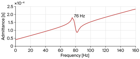
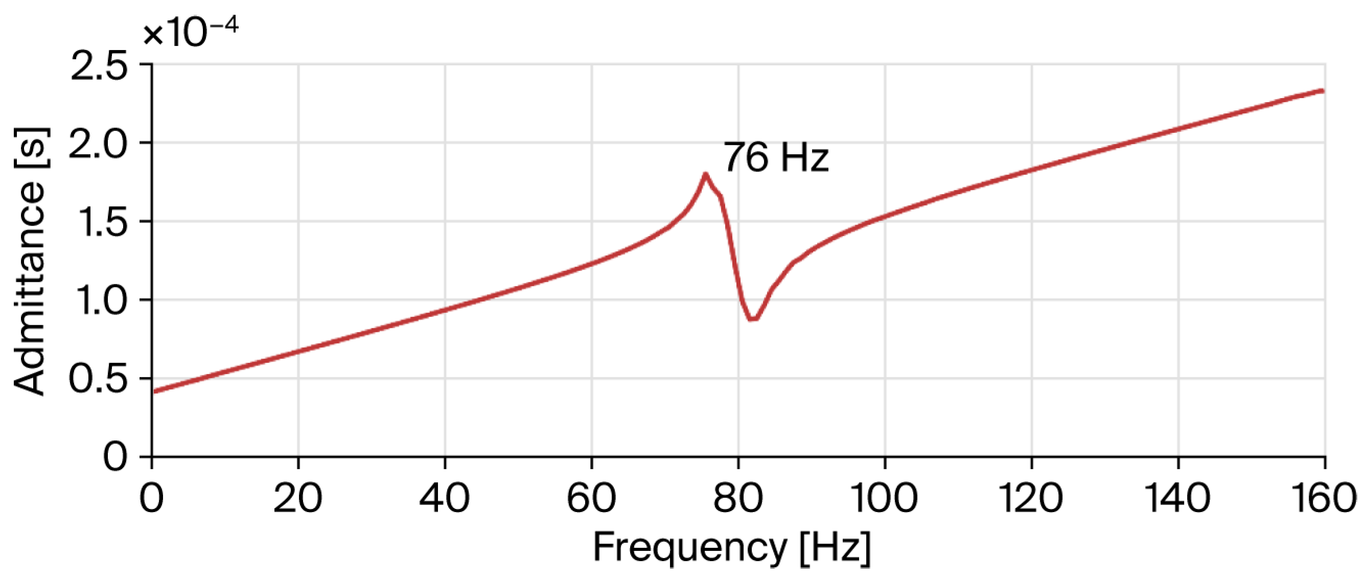
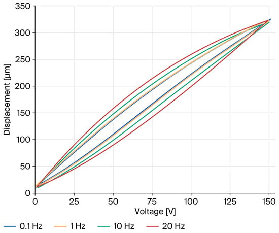
The dynamic performance of the nanopositioning stage was characterized using an impedance analyzer to corroborate its operational efficacy. As illustrated in Figure 8, a notable inflection point emerges at approximately 76 Hz, indicating that the actual resonance frequency is very close to the simulated prediction of 78.4 Hz. In general, the discrepancy between the theoretical material properties of the prototype model and the actual manufacturing tolerances, as well as defects introduced during fabrication, can result in significant deviations between the actual resonance frequency and the predicted value. Empirical data correlating output displacement with applied voltage were systematically recorded and illustrated in Figure 9. Experimentally, under a preloading force of 500 N and a maximum drive voltage of 150 V, compared with an estimated displacement output about 336 μm × 336 μm, the PZT actuator archived a workspace of 312 μm × 312 μm, which aligned with the simulated displacement output.
Figure 8.
Admittance curve of the nanopositioning stage.
Figure 9.
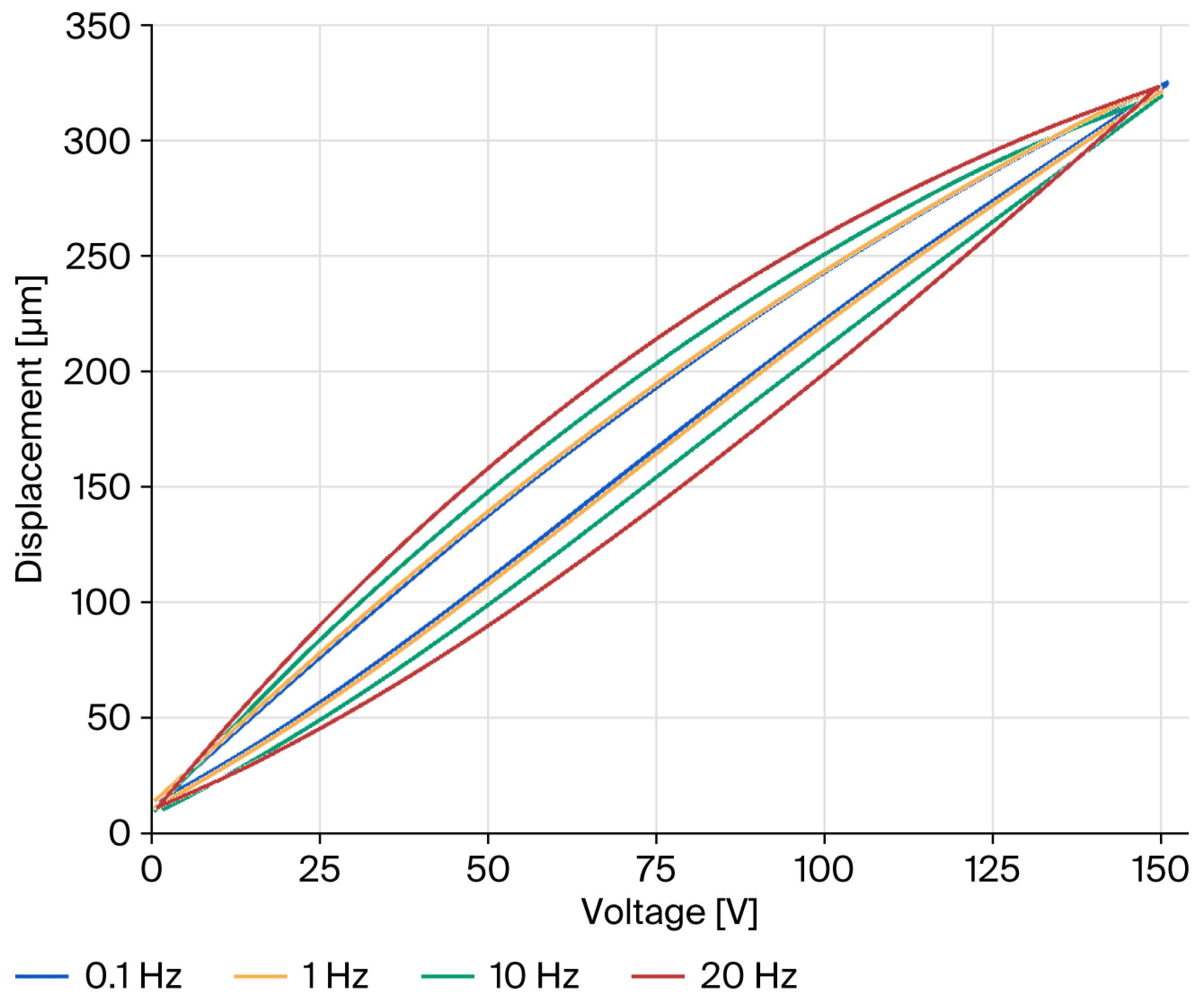
Open-loop hysteresis characteristics across different voltage frequencies.
The testing protocol involved the application of a series of non-negative triangular voltage waveforms at frequencies of 0.1 Hz, Hz, 10 Hz, and 20 Hz to the PZT actuators. The results elucidate a pronounced rate dependency of the hysteresis phenomenon: higher excitation frequencies engender broader hysteresis loops, indicative of exacerbated nonlinearity. While the mitigation of hysteresis nonlinearity lies beyond the scope of this investigation, it is amenable to amelioration through the implementation of a closed-loop feedback control strategy.
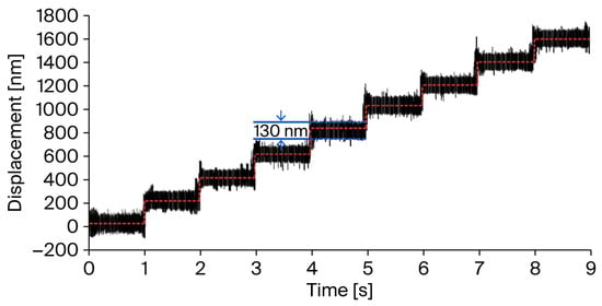
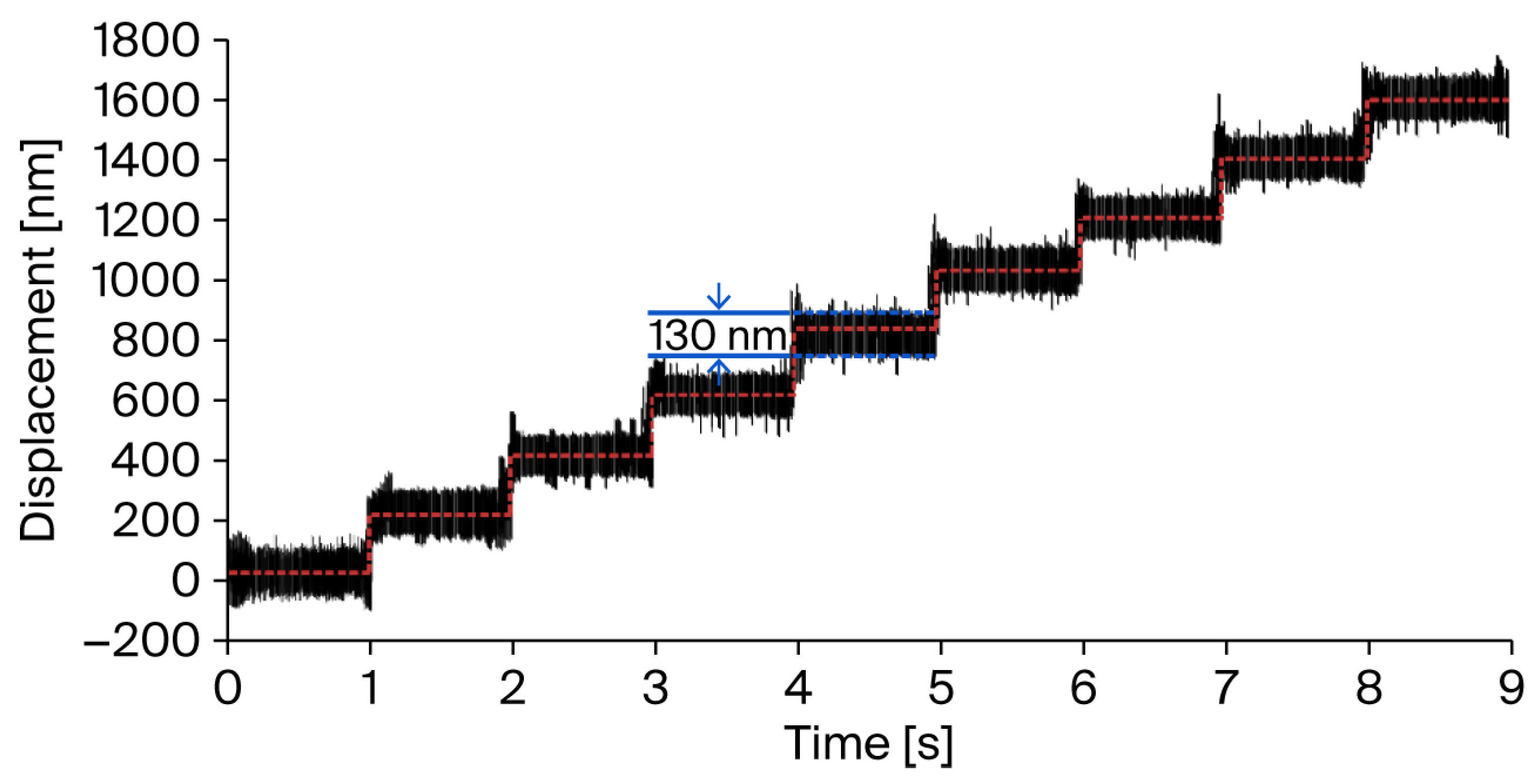
As illustrated in Figure 10, in typical open-environment conditions, the multistep response with a 130 nm step size was effectively resolved with open-loop feedback control. In this case, the minimum resolution was constrained by the sensor’s peak-to-peak noise of 130 nm@40 kHz.
Figure 10.
Minimum resolution test result.
When evaluating the performance of a PZT nanopositioning platform, it is essential to consider a range of performance metrics, including stroke, resonant frequency, resolution, coupling error, and dimension of the mechanism. These performance parameters are often interdependent, rendering direct comparisons between individual stages challenging. To facilitate an objective assessment, the concept of “area efficiency” (defined as the ratio of workspace area to mechanism area) introduced in reference [22] is employed. A higher area efficiency indicates a more compact and thus more effective nanopositioning stage. For a comprehensive comparison with the proposed PZT nanopositioning stages, several representative mechanisms are summarized in Table 3. The area efficiency value of the proposed stage is much higher than the other stages, confirming its superior performance and suitability for miniaturization.
Table 3.
Performance comparison of the nanopositioning stage.
5. Conclusions
The detailed design of an XY PZT nanopositioning platform is presented. A compact multi-stage amplification mechanism, integrating a rhombus amplifier and a lever amplifier, is introduced to augment the platform’s workspace. A pseudo-static model was employed for dynamic modeling analysis of the entire system, transforming the dynamic modeling of the compliant mechanism into a static-like problem, thereby simplifying the modeling process for complex compliant mechanisms. The performance of the established model was validated using FEA software (ANSYS Workbench 19.2). The prototype machine was independently manufactured and tested. Experimental results demonstrate that the stage achieves a workspace of 312 μm × 312 μm, a fundamental frequency of 76 Hz, and compact dimensions of 173.5 mm × 93 mm × 10 mm. The experimental results show that the PZT platform can be widely used in the field of precise positioning, and demonstrate the platform’s potential for further miniaturization. As precise rate-dependent hysteresis models are promising to solve frequency-dependent effects of PZT actuators, future research will focus on the implementation of hysteresis compensation and frequency response analysis, which is essential for high-precision positioning applications.
Author Contributions
Conceptualization, J.Y.; methodology, J.Y. and C.Z.; software, D.L.; validation, J.Y., C.Z. and X.C.; formal analysis, J.Y. and C.Z.; data curation, J.Y.; writing—original draft preparation, C.Z.; writing—review and editing, C.Z. and X.C.; supervision, D.L.; funding acquisition, J.Y. All authors have read and agreed to the published version of the manuscript.
Funding
This research was funded by Anhui Province Science and Technology Innovation Tackling Program (202523j08050014) and Anhui Provincial Key Laboratory of Electronic Information System Simulation, Computing and Design—Open Fund (2024KYPT07). The APC was funded by 202523j08050014.
Institutional Review Board Statement
Not applicable.
Informed Consent Statement
Not applicable.
Data Availability Statement
The data that support the findings of this study are available on request from the corresponding author, upon reasonable request.
Conflicts of Interest
The authors declare no conflicts of interest.
References
- Wu, Z.; Wu, Z.; Chen, I.-M.; Xu, Q. Recent Advances in Piezoelectric Compliant Devices for Ultrahigh-Precision Engineering. Micromachines 2024, 15, 1456. [Google Scholar] [CrossRef] [Scilit]
- Zhang, T.; Xiong, L.; Pan, Z.; Zhang, C.; Qu, W.; Wang, Y.; Yang, C. Design and Analysis of XY Large Travel Micro Stage Based on Secondary Symmetric Lever Amplification. Micromachines 2023, 14, 1805. [Google Scholar] [CrossRef] [Scilit]
- Tang, H.; Li, Y. Development and Active Disturbance Rejection Control of a Compliant Micro-/nanopositioning Piezostage with Dual Mode. IEEE Trans. Ind. Electron. 2014, 61, 1475–1492. [Google Scholar] [CrossRef] [Scilit]
- Noveanu, S.; Lobontiu, N.; Lazaro, J.; Mandru, D. Substructure Compliance Matrix Model of Planar Branched Flexure-hinge Mechanisms: Design, Testing and Characterization of a Gripper. Mech. Mach. Theory 2015, 91, 1–20. [Google Scholar] [CrossRef] [Scilit]
- Zhu, W.; Yang, X.; Duan, F.; Zhu, Z.; Ju, B. Design and Adaptive Terminal Sliding Mode Control of a Fast Tool Servo System for Diamond Machining of Freeform Surfaces. IEEE Trans. Ind. Electron. 2019, 66, 4912–4922. [Google Scholar] [CrossRef] [Scilit]
- Xu, Q. Design, Testing and Precision Control of a Novel Long-stroke Flexure Micropositioning System. Mech. Mach. Theory 2013, 70, 209–224. [Google Scholar] [CrossRef] [Scilit]
- Shang, J.; Tian, Y.; Li, Z.; Wang, F.; Cai, K. A Novel Voice Coil Motor-driven Compliant Micropositioning Stage Based on Flexure Mechanism. Rev. Sci. Instrum. 2015, 86, 095001. [Google Scholar] [CrossRef] [Scilit] [PubMed]
- Yong, Y.; Liu, K.; Reza Moheimani, S. Reducing Cross-Coupling in a Compliant XY Nanopositioner for Fast and Accurate Raster Scanning. IEEE Trans. Control Syst. Technol. 2009, 18, 1172–1179. [Google Scholar] [CrossRef] [Scilit]
- Wang, F.; Liang, C.; Tian, Y.; Zhao, X.; Zhang, D. Design and Control of a Compliant Microgripper with a Large Amplification Ratio for High-Speed Micro Manipulation. IEEE/ASME Trans. Mechatron. 2016, 21, 1262–1271. [Google Scholar] [CrossRef] [Scilit]
- Tang, H.; Li, Y. Feedforward Nonlinear PID Control of a Novel Micromanipulator Using Preisach Hysteresis Compensator. Robot. Comput. Integr. Manuf. 2015, 34, 124–132. [Google Scholar] [CrossRef] [Scilit]
- Zhu, W.; Yang, X.; Duan, F.; Zhu, Z.; Ju, B. Design, Modeling, Analysis and Testing of a Novel Piezo-actuated XY Compliant Mechanism for Large Workspace Nano-positioning. Smart Mater. Struct. 2016, 25, 115033. [Google Scholar] [CrossRef] [Scilit]
- Pokines, B.; Garcia, E. A Smart Material Microamplification Mechanism Fabricated Using LIGA. Smart Mater. Struct. 1998, 7, 105. [Google Scholar] [CrossRef] [Scilit]
- Sohail, I.; Shakoor, R.; Gilani, H.; Hussain, A.; Malik, A. Performance Analysis of Microelectromechanical System Based Displacement Amplification Mechanism. Iran. J. Sci. Technol. Trans. Mech. Eng. 2019, 43, 507–528. [Google Scholar] [CrossRef] [Scilit]
- Xu, Q.; Li, Y. Analytical Modeling, Optimization and Testing of a Compound Bridge-type Compliant Displacement Amplifier. Mech. Mach. Theory 2011, 46, 183–200. [Google Scholar] [CrossRef] [Scilit]
- Li, Y.; Huang, J.; Tang, H. A Compliant Parallel XY Micromotion Stage with Complete Kinematic Decoupling. IEEE Trans. Autom. Sci. Eng. 2012, 9, 538–553. [Google Scholar] [CrossRef] [Scilit]
- Tang, H.; Li, Y. Design, Analysis, and Test of a Novel 2-DOF Nanopositioning System Driven by Dual Mode. IEEE Trans. Robot. 2013, 29, 650–662. [Google Scholar] [CrossRef] [Scilit]
- Gan, J.; Zhang, X. A review of nonlinear hysteresis modeling and control of piezoelectric actuators. AIP Adv. 2019, 9, 040702. [Google Scholar] [CrossRef] [Scilit]
- Delibas, B.; Arockiarajan, A.; Seemann, W. Rate dependent properties of perovskite type tetragonal piezoelectric materials using micromechanical model. Int. J. Solids Struct. 2006, 43, 697–712. [Google Scholar] [CrossRef] [Scilit]
- Ao, Y.; Jin, L.; Wang, S.; Lan, B.; Tian, G.; Xu, T.; Huang, L.; Wang, Z.; Sun, Y.; Yang, T.; et al. Dual structure reinforces interfacial polarized MXene/PVDF-TrFE piezoelectric nanocomposite for pressure monitoring. Nano-Micro Lett. 2025, 17, 320. [Google Scholar] [CrossRef] [Scilit] [PubMed]
- Ling, M.; Howell, L.; Cao, J.; Jiang, Z. A Pseudo-static Model for Dynamic Analysis on Frequency Domain of Distributed Compliant Mechanisms. J. Mech. Robot.-Trans. ASME 2018, 10, 051011. [Google Scholar] [CrossRef] [Scilit]
- Kim, J.; Choi, Y.; Ahn, D.; Hwang, B.; Gweon, D.; Jeong, J. A Millimeter-range Flexure-based Nano-positioning Stage Using a Self-guided Displacement Amplification Mechanism. Mech. Mach. Theory 2012, 50, 109–120. [Google Scholar] [CrossRef] [Scilit]
- Tang, H.; Li, Y. A New Flexure-based Nanomanipulator with Nanometer-scale Resolution and Millimeter-scale Workspace. IEEE-ASME Trans. Mechatron. 2015, 20, 1320–1330. [Google Scholar] [CrossRef] [Scilit]
- Zhu, X.; Xu, X.; Wen, Z.; Ren, J.; Liu, P. A Novel Flexure-based Vertical Nanopositioning Stage with Large Travel Range. Rev. Sci. Instrum. 2015, 86, 105112. [Google Scholar] [CrossRef] [Scilit] [PubMed]

Disclaimer/Publisher’s Note: The statements, opinions and data contained in all publications are solely those of the individual author(s) and contributor(s) and not of MDPI and/or the editor(s). MDPI and/or the editor(s) disclaim responsibility for any injury to people or property resulting from any ideas, methods, instructions or products referred to in the content. |
© 2026 by the authors. Licensee MDPI, Basel, Switzerland. This article is an open access article distributed under the terms and conditions of the Creative Commons Attribution (CC BY) license.