


Abstract
This paper presents a dual-axis micro-displacement measurement system based on double-layer grating interference adopting a quasi-common-mode optical configuration. Utilizing the diffraction and interference effects of the grating pair, the system realizes decoupled high-precision dual-axis displacement measurement by detecting diffracted light intensity induced by out-of-plane and in-plane motions of the movable grating. The light-intensity response originating from grating-pair diffraction is theoretically derived to establish the quantitative relationship between displacement and optical intensity. An experimental setup is constructed to record intensity variation curves for out-of-plane and in-plane motions. Measurement accuracy along the two axes is systematically analyzed over a 1 mm working range. Experimental results yield a full-scale accuracy of 0.0039% and a resolution of 0.38 nm for out-of-plane displacement, while the in-plane displacement measurement achieves a full-scale accuracy of 0.08% with 19 nm resolution. Benefiting from its compact architecture, nanoscale resolution, and superior measurement precision, the proposed grating-pair scheme opens a new avenue for multi-dimensional micro-displacement sensing.
1. Introduction
High-precision micro-displacement measurement serves as an essential technology in advanced equipment fields including precision mechanical assembly, ultra-precision machining, and semiconductor manufacturing, where measurement accuracy and stability directly determine processing quality and device performance [1,2,3,4,5]. Currently [6,7,8], mainstream micro-displacement sensing approaches mainly include capacitive, piezoelectric, and grating-based techniques. Piezoelectric sensors are susceptible to hysteresis and nonlinear errors, which make it challenging to guarantee measurement accuracy over large ranges under complex operating conditions. Capacitive sensors [9,10,11] are restricted by parasitic capacitance interference and fringe effects, and they are highly susceptible to various environmental perturbations. Owing to these intrinsic drawbacks, the aforementioned methods can hardly guarantee multi-dimensional micro-displacement measurement featuring ultra-high precision, high resolution, and a large measurement range. By contrast, grating-based micro-displacement measurement exhibits the distinct advantages of non-contact detection, high resolution, strong electromagnetic-interference immunity, and fast dynamic response. Nevertheless, most existing two-dimensional grating interferometry schemes adopt bulky multi-beam spatial-separation optics. Such configurations introduce non-common-path optical path differences, making measurement results vulnerable to air turbulence, temperature drift, and mechanical vibration, and additional optical components also increase system volume and integration difficulty. Accordingly, compact multi-dimensional grating-interferometry solutions with quasi-common-path features are highly desirable for practical precision metrology [12,13].
Existing studies primarily employ two-dimensional gratings, spatial beam separation, and multi-order diffraction to realize high-precision, high-resolution, large-range micro-displacement sensing [14,15,16,17,18,19,20,21,22,23,24,25]. D. Chang et al. [14] adopted multi-beam grating interferometry to construct a Littrow-type cavity integrated with a diffraction grating, and carried out displacement experiments spanning approximately 10 μm. D. Guo et al. [15] integrated two-dimensional crossed gratings with self-mixing interferometry and frequency-division multiplexing to realize three-dimensional displacement measurement within an approximate 8 μm range. Z. Zhang et al. [20] realized 16-fold optical subdivision within a grating measurement system via optimized layout of mirror-grating separations for blazed gratings, achieving 26 nm resolution over a 1.7 mm range. These approaches exhibit an inherent trade-off between accuracy and range, where high accuracy is confined to narrow spans and large-range operation yields low resolution. Simultaneous realization of multi-dimensional sensing with high resolution, large range, high precision, and strong environmental robustness remains a considerable challenge.
To address these challenges, this work proposes a micro-displacement measurement method based on double-layer grating interferometry with a quasi-common-path optical configuration. A single grating-pair configuration is implemented to accomplish decoupled dual-axis displacement measurement, avoiding complicated multi-beam separation assemblies. Experimental results show that the out-of-plane displacement measurement achieves a full-scale accuracy of 0.0039% and a resolution of 0.38 nm, while the in-plane counterpart delivers 0.08% full-scale accuracy and 19 nm resolution. The proposed method provides a simplified approach for miniaturized, high-precision dual-axis micro-displacement sensing.
2. The Principle of Micro-Displacement Measurement Based on Grating Pair Structure
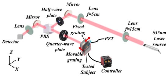
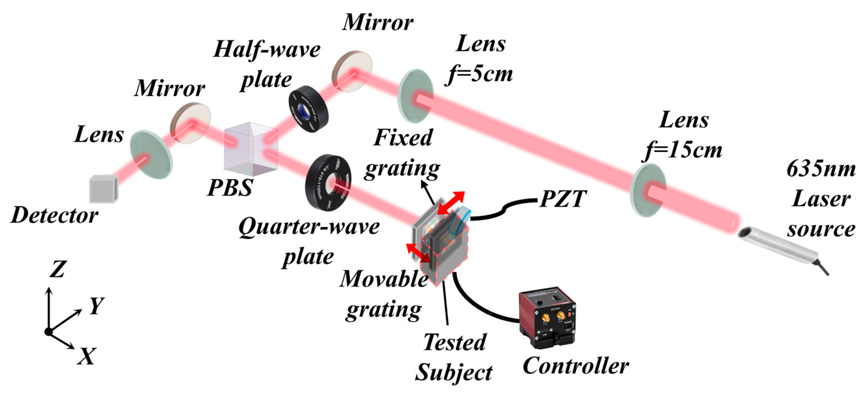
An experimental setup shown in Figure 1 was constructed to characterize the performance of the proposed two-axis micro-displacement sensing system. Different from conventional multi-component, multi-beam 2D grating interferometers, this test setup employs a grating-pair-based quasi-common-path architecture to suppress common-mode environmental disturbances.
Figure 1.
Experimental setup of the two-axis micro-displacement sensor based on quasi-common-path grating-pair interference.
Laser light emitted by a Thorlabs CPS635R laser source (λ = 635 nm) is collimated sequentially via lenses of 5 cm and 15 cm focal length. The collimated beam is reflected by a mirror onto a half-wave plate (λ/2) for polarization-direction adjustment. Afterwards, the beam enters a polarizing beam splitter (PBS), is deflected angularly by a prism, transmits through a quarter-wave plate (λ/4), and illuminates the stationary diffraction grating. The mount orientation is adjusted so that the zero-order diffracted light from the stationary grating overlaps the incident beam, ensuring that light diffracted by the stationary grating precisely illuminates the movable grating. The test object is mounted on a holder connected to the movable-grating stage; its orientation is tuned so that zero-order diffracted light from the movable grating overlaps the incident light. Under this alignment condition, zero-order diffracted beams from the two grating layers interfere with each other. Micro-displacement of the target drives the movable grating, and the recombined beam propagates backward through the PBS, is reflected by a mirror, focused by a 15 cm focal-length lens, and finally reaches the photodetector.
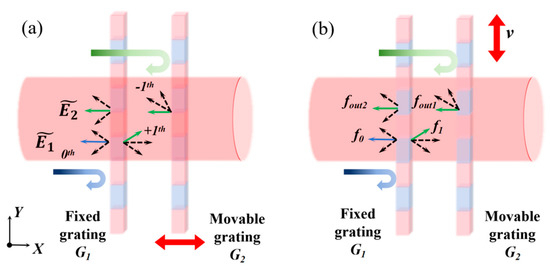
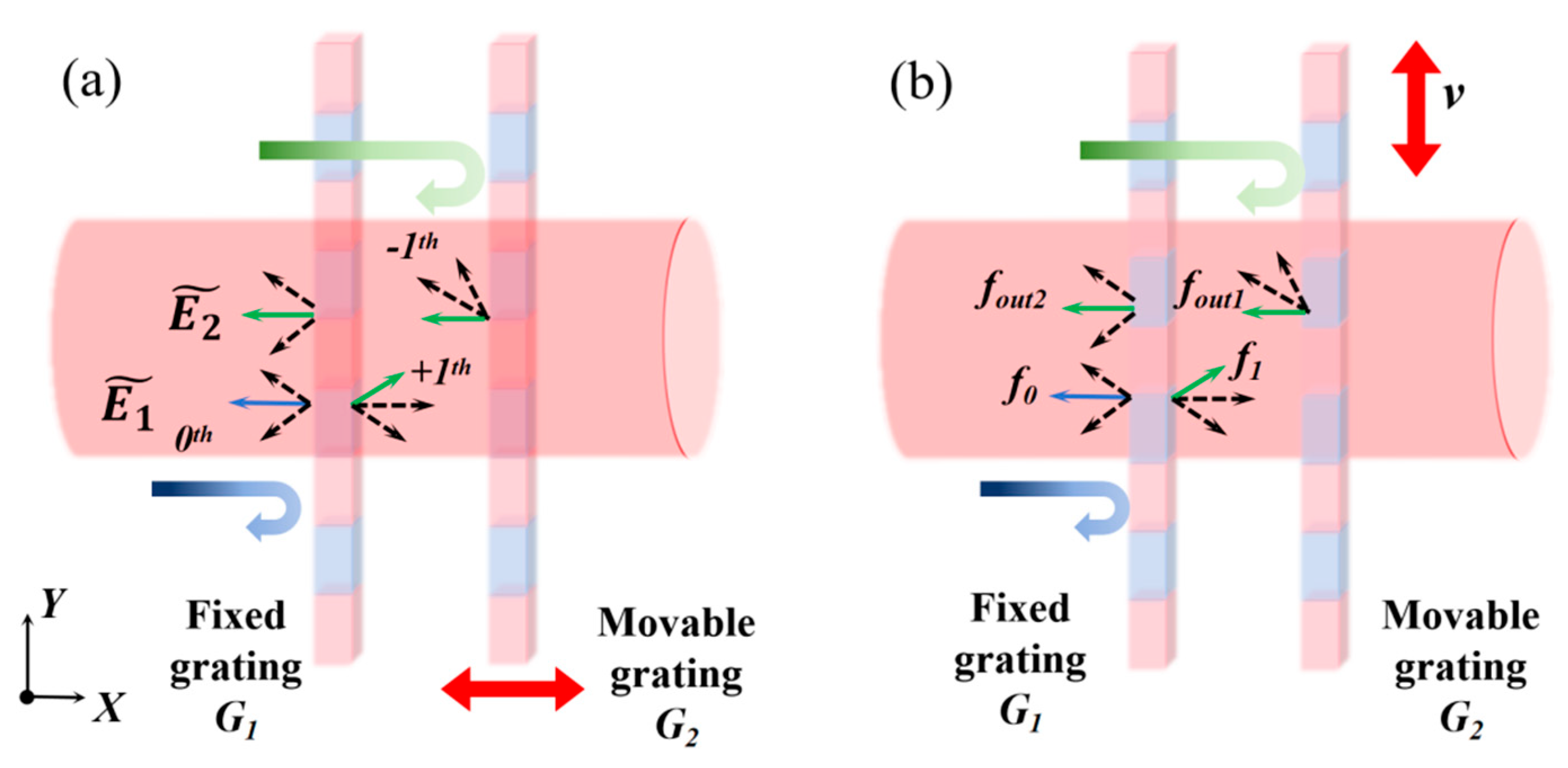
This work presents a micro-displacement sensing system that enables dual-axis micro-displacement measurement utilizing a single grating pair arranged in a quasi-common-path layout. The sensing mechanism relies on grating diffraction and multi-beam interference, exploiting optical responses triggered by both in-plane and out-of-plane displacements. A schematic of the detection principle is illustrated in Figure 2. Incident light impinges perpendicularly on the fixed grating. When the measured target undergoes micro-displacement, the movable grating rigidly attached to the target moves synchronously. Relative positional changes between the movable and fixed gratings produce periodic modulation of the output light intensity. A high-sensitivity photodetector captures the modulated optical signal, allowing real-time dual-axis micro-displacement acquisition.
Figure 2.
Schematic diagram of the two-dimensional micro-displacement measurement system based on grating interferometry. Principle of (a) out-of-plane and (b) in-plane micro-displacement measurement.
2.1. Out-of-Plane Measurement Principle
Out-of-plane motion of the movable grating layer along the X-axis induces three successive grating diffractions within the quasi-common-path optical system, as depicted in Figure 2a. The 635 nm laser light is incident on the fixed grating G1 and generates reflected diffracted light E1 as well as transmitted diffracted light. The +1st-order transmitted diffraction beam propagates toward movable grating G2. The −1st-order reflected diffracted beam travels backward to G1 and generates a 0-order transmitted diffracted beam E2. These two diffracted beams, which propagate along largely overlapping optical paths, interfere and subsequently couple into the photodetector.
Based on scalar Fraunhofer diffraction theory, the normalized complex amplitude for the diffracted beam reflected by fixed grating G1 is given by:
where C denotes the single-slit incident-light amplitude, N is the total number of grating periods, αref1 = π/λ·Λ·(1 − p)·sin θ represents the single-slit diffraction factor, θ is the diffraction angle, Λ stands for the grating period, and p is the duty ratio of the grating. The multi-slit diffraction factor is defined as δref1 = 2π/λ·Λ·sin θ, describing the optical-path difference for diffracted light originating from adjacent slits.
The complex amplitude of diffracted light transmitted through G1 is expressed as:
where αtrans1 = π/λ·Λ·p·sin θ = πp, δtrans1 = 2π/λ·Λ·sin θ = 2π, and .
Given the reflective-diffraction light transfer function , the complex amplitude after reflection diffraction at the second grating is expressed as:
The complex amplitude for grating transmission diffraction is:
Finally, the interference intensity produced by the two diffracted laser components is expressed as:
where , . It can be concluded that the diffraction intensity curve varies sinusoidally with displacement, featuring a period of approximately λ/2.
2.2. In-Plane Measurement Principle
The working principle for in-plane micro-displacement measurement based on the quasi-common-path grating-pair interferometry is shown in Figure 2b. Laser light of frequency f0 is normally incident on the fixed grating G1 and generates diffraction. The diffracted angle satisfies the grating equation Λsin θm = mλ, where m represents the diffraction order from fixed grating G1. Since fixed grating G1 remains stationary, the frequency of the diffracted light is identical to that of the incident light, i.e., f1 = f0.
Diffracted light from the fixed grating G1 illuminates movable grating G2, which undergoes in-plane translation along the Y-axis with velocity v. The frequency fout1 of the nth-order diffracted light after G2 is written as:
where c = λf0 is the speed of light and n represents the diffraction order after movable grating G2. The frequency shift generated by G2 is , which is independent of the speed of light and is solely governed by grating velocity v, grating period, and diffraction order n.
After diffraction at movable grating G2, reflected light propagates back towards fixed grating G1 and diffracts again. As fixed grating G1 remains stationary, the diffracted light retains the same frequency as the light incident on G1, namely fout2 = fout1. The frequency shift after the third diffraction at G1 satisfies Δf = 0. Hence, the total frequency shift in the system equals .
The phase difference induced by the frequency shift is . The displacement of movable grating G2 is denoted as ∆x, yielding the following relation for phase difference:
From the above formula, when movable grating G2 produces a relative displacement of one grating period Λ with respect to fixed grating G1, the phase distribution at an arbitrary position across the interference region undergoes a full 2π periodic variation. Such phase modulation causes the interferometric light-intensity signal to vary through one complete sinusoidal cycle. Consequently, micro-displacement magnitude can be retrieved by counting these light-intensity periodic oscillations. Notably, both out-of-plane and in-plane displacement information can be decoded from intensity signals acquired by the same photodetector, realizing 2-DOF measurement within one compact quasi-common-path optical setup.
3. Experimental Results and Discussion
To characterize the practical system resolution, a piezoelectric ceramic actuator (Model E53.B1S, Coremorrow Inc., Harbin, China) is used as the micro-displacement generator. The entire system is placed on an active vibration-isolation table (Model TS-150, HERZ, Yokohama, Japan) to suppress external vibrational disturbances. Driven by periodic voltage U, the piezoelectric ceramic performs periodic reciprocating displacement ΔL. The relation between the output displacement and driving voltage is expressed by:
where d33 = 635 pm/V, n = 250, and U is the applied driving voltage. The PZT provides displacement inputs with known amplitude, and the minimum resolvable displacement amplitude is defined as practical system resolution. A low-pass filter is applied to acquired signals for high-frequency noise suppression.
∆L = d33 × n × U × 12
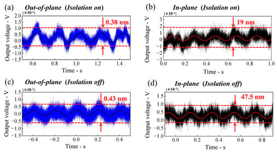
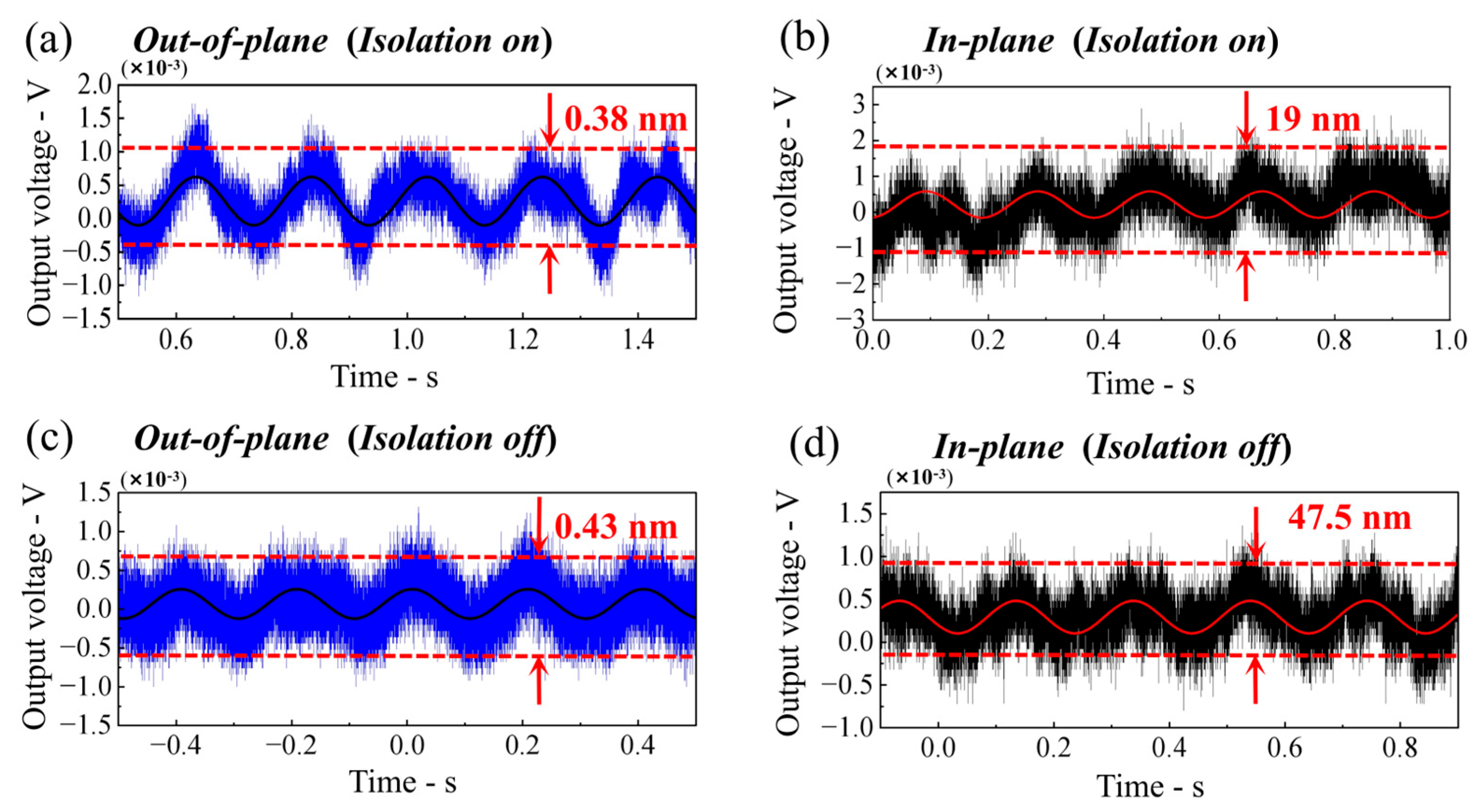
To quantify vibration–noise influence and verify the anti-disturbance merit brought by quasi-common-path design, measurements are carried out under both activated and deactivated states of the vibration-isolation table. With vibration isolation enabled, the system resolves displacement amplitudes of 0.38 nm (out-of-plane) and 19 nm (in-plane), corresponding to Figure 3a,b. When vibration isolation is switched off, resolvable amplitudes degrade to 0.43 nm and 47.5 nm (Figure 3c,d). In all cases, output-signal oscillation frequencies match the driving-voltage frequency, yet exhibit noticeable amplitude fluctuations. This confirms that observed responses originate from PZT-induced physical displacement rather than random noise. Disabling vibration isolation degrades resolution by roughly 13% for the out-of-plane direction and causes a 1.5-fold degradation in the in-plane direction. Although in-plane measurement remains more susceptible to vibrational interference due to its larger signal period, the quasi-common-path layout still provides notable common-mode noise suppression compared with fully separated multi-beam optical paths. Furthermore, out-of-plane resolution is one order of magnitude superior to in-plane resolution, which agrees well with theoretical predictions.
Figure 3.
Resolution measurement results of the proposed system. (a) Out-of-plane and (b) in-plane with the vibration isolation activated; (c) out-of-plane and (d) in-plane with the vibration isolation deactivated.
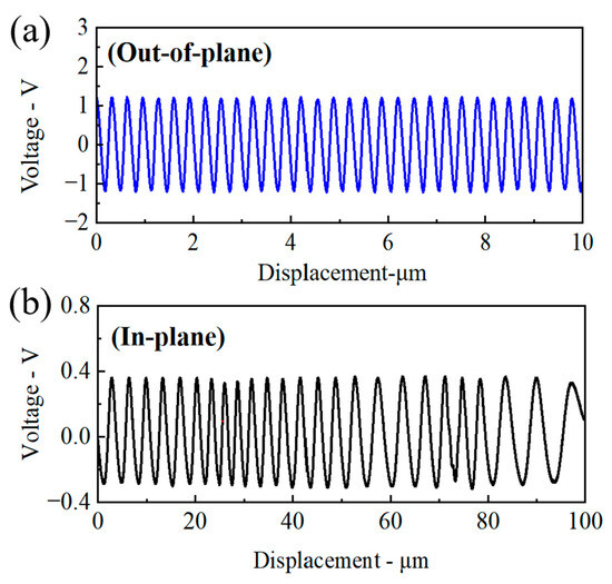
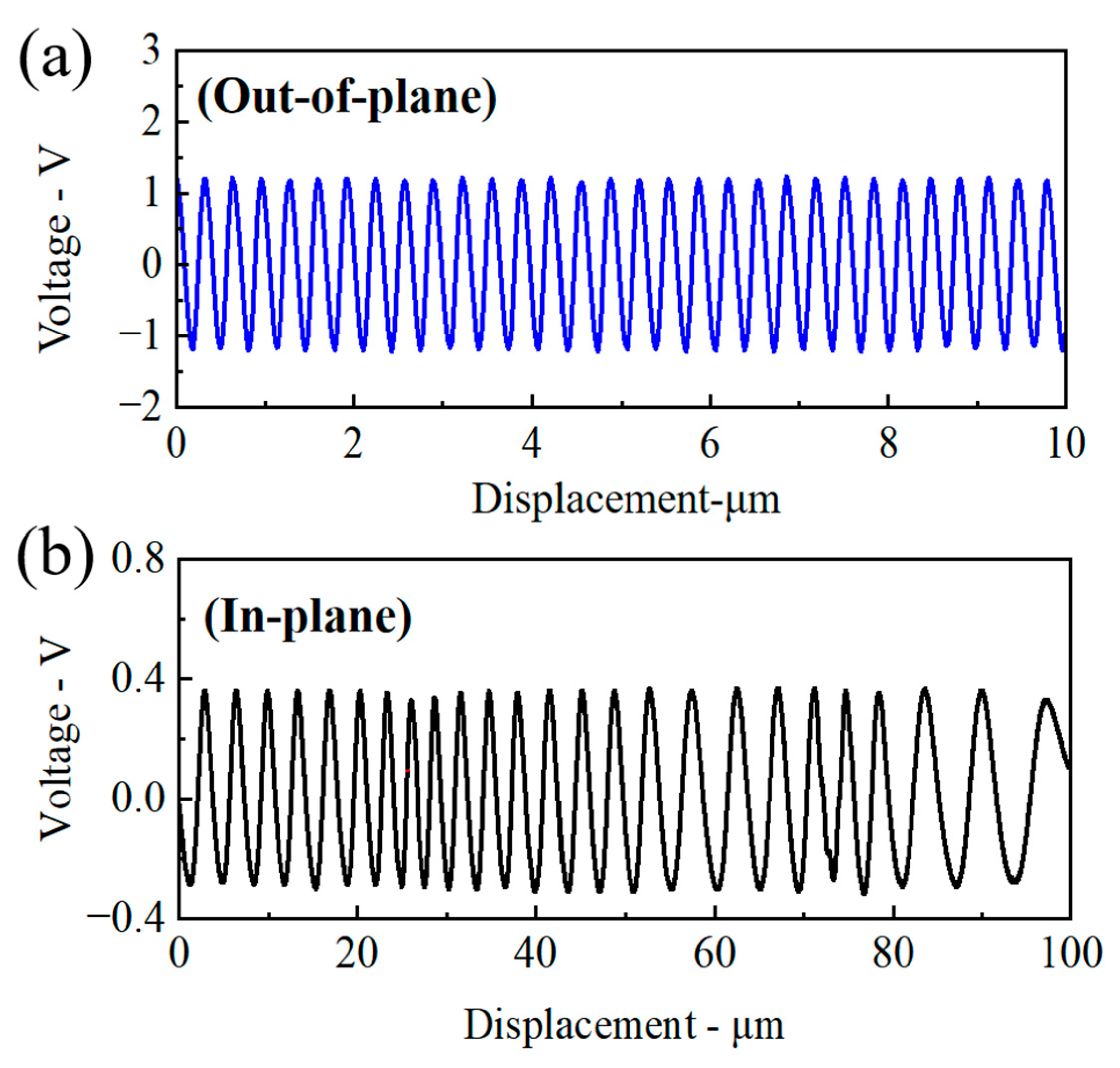
Beyond practical resolution, measurement accuracy and repeatability of the system are systematically evaluated. Figure 4 presents measured interference signals of the sensing system after amplification. Out-of-plane (X-axis) and in-plane (Y-axis) signals maintain stable periodic waveforms with nearly constant amplitude over the 0–10 μm range and 0–100 μm range, respectively. The periodic intensity modulation confirms that the quasi-common-path system can effectively extract valid displacement signals. Consistent with the theoretical analysis, a 10 μm out-of-plane displacement yields 30.5 signal cycles while a 100 μm in-plane displacement yields 25 signal cycles. After passing through the phase-shift module, two orthogonal signals are produced and fed into the subdivision interpolation circuit, which outputs standard incremental orthogonal pulses. Each output pulse represents a theoretical displacement resolution after interpolation by the DSP interpolator. The displacement is therefore recovered by counting the output pulses and multiplying by this per-pulse resolution.
Figure 4.
Measured interference signals of the proposed two-dimensional micro-displacement sensing system. (a) Out-of-plane displacement signal along the X-axis over the 0–10 μm range; (b) In-plane displacement signal along the Y-axis over the 0–100 μm range.
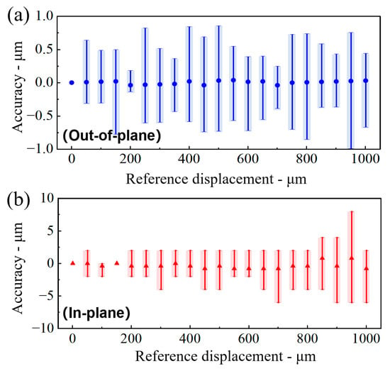
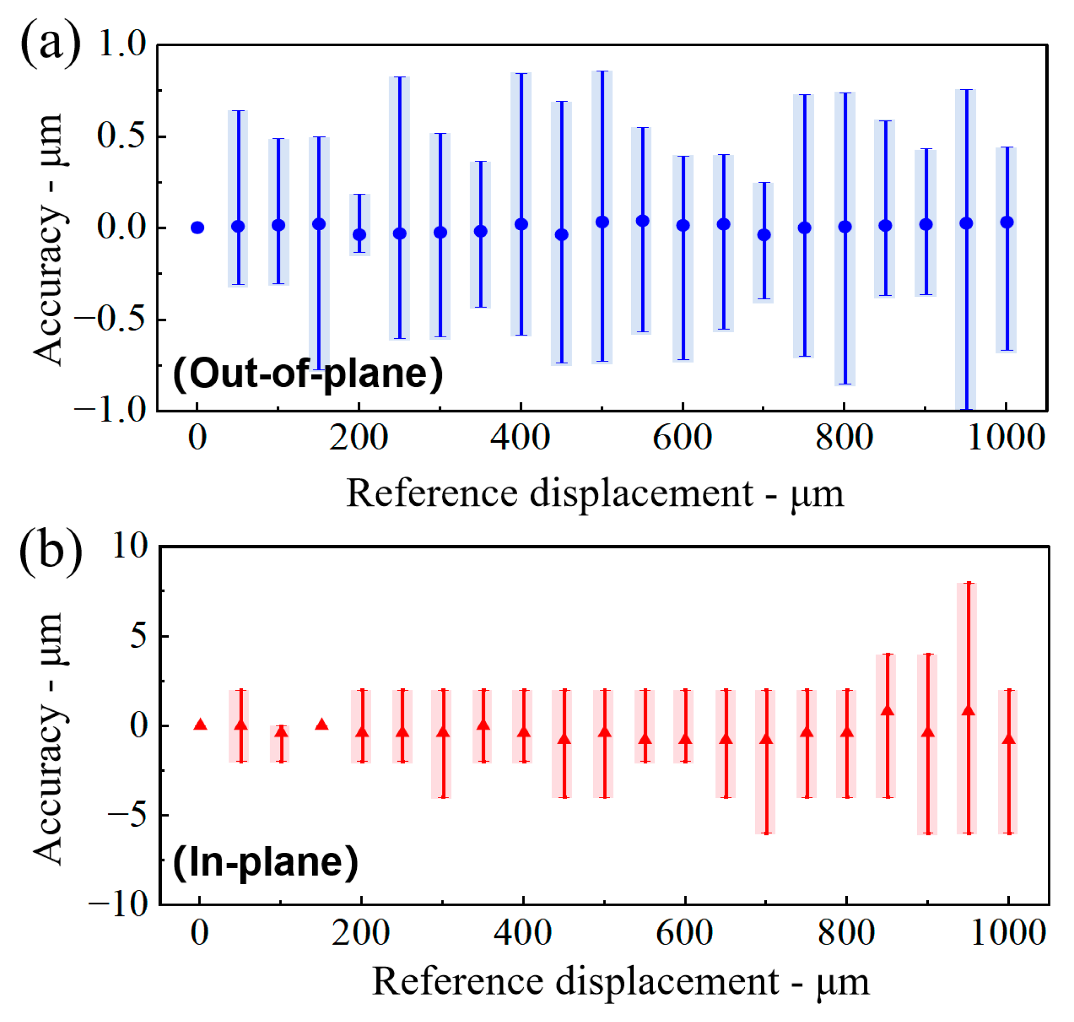
A commercial motion controller with an accuracy of ±0.2 μm@12 mm is used as a reference standard. Twenty step-wise micro-displacement commands ranging from 50 μm to 1 mm (50 μm step interval) are sequentially output along the X-axis. Each reference displacement is measured five times, and the measurement errors relative to the input are calculated from recorded data. Figure 5a plots measurement errors derived from five repeated measurements as a function of the reference displacement along the X-axis. Within the 0–1 mm range, out-of-plane measurement accuracy reaches 0.039 μm; full-scale nonlinearity is 0.0047%. Identical test procedures are executed for the Y-axis as shown in Figure 5b. For the in-plane direction, measurement accuracy is 0.8 μm, with full-scale accuracy of 0.08% and full-scale relative nonlinearity of 0.1124%.
Figure 5.
(a) Measurement accuracy and repeatability measurement results along the (a) out-of-plane direction (X-axis) and (b) in-plane direction (Y-axis) within the range of 0~1 mm.
For comprehensive performance assessment, recently reported two-dimensional displacement measurement systems with diverse working principles are selected for quantitative performance comparison, as listed in Table 1. Distinguished from most competing 2D grating-interferometry solutions that require complicated multi-beam spatial-separation optics, this work proposes and experimentally validates a dual-axis micro-displacement sensing principle built upon double-layer grating interference adopting a quasi-common-path configuration. Benefiting from this optical architecture, environmental common-mode errors can be intrinsically suppressed, and two-axis measurement is realized using only one grating-pair assembly, reducing system complexity and volume. The system achieves a practical out-of-plane resolution of 0.38 nm. Although constrained by the mechanical noise of the piezoelectric actuator, this value still outperforms many existing micro-displacement sensors. Moreover, full-scale accuracy along the X-axis reaches as low as 0.0039%, demonstrating competitive overall measurement performance. Compared with conventional inductive, capacitive, and Talbot-effect-based sensors, the proposed system requires neither large-area electrodes nor intricate coil assemblies. It exhibits distinct advantages in resolution, miniaturization, and multi-dimensional integration potential and delivers a feasible solution for high-integration, low-cost precision displacement detection.
Table 1.
Performance comparison of the proposed method with other micro-displacement measurement techniques.
4. Conclusions
This paper proposes and experimentally validates a two-dimensional micro-displacement measurement method based on double-layer grating interference with a quasi-common-path optical configuration. Relying on a single grating-pair assembly, decoupled multi-dimensional displacement measurement for both out-of-plane and in-plane axes is realized, without bulky multi-beam spatial-separation components. High-precision dual-axis displacement measurement is achieved by capturing the light intensity of interfering diffracted light generated by relative out-of-plane and in-plane motions. Within a 1 mm measurement range, the out-of-plane measurement attains an accuracy of 0.039 μm and a resolution of 0.38 nm, whereas the in-plane measurement yields an accuracy of 0.8 μm together with a resolution of 19 nm. Benefiting from its compact mechanical layout and nanoscale resolution alongside sub-micrometer-level measurement accuracy, the system is well suited for practical application scenarios including precision positioning and MEMS characterization. Future work will further optimize the optical layout to improve in-plane resolution and expand the measurable range of multi-dimensional displacement.
Author Contributions
Conceptualization, L.J. and K.L.; methodology, L.J., M.L., and K.L.; software, K.X. and Y.G.; validation, C.Z. and K.L.; formal analysis, L.J. and K.X.; investigation, K.L.; data curation, L.J. and C.Z.; writing—original draft preparation, K.L. and C.Z.; writing—review and editing, K.L., L.J., and M.L.; project administration, L.J. All authors have read and agreed to the published version of the manuscript.
Funding
Supported by the Fundamental Research Program of Shanxi Province (No. 202403021221122).
Institutional Review Board Statement
Not applicable.
Informed Consent Statement
Not applicable.
Data Availability Statement
The data underlying the results presented in this paper are not publicly available at this time but may be obtained from the authors upon reasonable request.
Acknowledgments
We would like to acknowledge the support from the fabrication platform of the Suzhou Institute of Nano-Tech and Nano-Bionics, Chinese Academy of Sciences.
Conflicts of Interest
The authors declare no conflicts of interest.
References
- Algoos, Y.; Lenz, W.B.; Khan, F.; Younis, M.I. An electrostatically actuated MEMS microgripper with high amplification for precision manipulation. Sens. Actuators A Phys. 2024, 378, 115800. [Google Scholar] [CrossRef] [Scilit]
- Cherkasova, V.; Fröhlich, T. Force-displacement measurement system with electromagnetic and electrostatic force compensation principles. TM-Tech. Mess. 2024, 91, 8–13. [Google Scholar] [CrossRef] [Scilit]
- Li, H.; Wang, B.; Liu, Z.; Zhao, J.; Wang, P. Smart ultra-precision machining system integrated with online monitoring of machined surface profile accuracy and real-time error compensation. J. Manuf. Syst. 2026, 86, 600–611. [Google Scholar] [CrossRef] [Scilit]
- Chang, Z.; Song, S.; Han, X.; Zhang, H.; Wei, Y.; Xiao, G.; Deng, X.; Xue, D.; He, C.; Xie, Y.; et al. Cr atom lithography grating and wavelet-based phase demodulation self-mixing interferometer for traceable nanoscale displacement metrology. Opt. Laser Technol. 2025, 189, 113137. [Google Scholar] [CrossRef] [Scilit]
- Xu, X.; Gu, D.; Gao, S.; Sun, L.; Lu, X.; Wang, K.; Bai, J. Back to Michelson interferometer: A precise inspection system for industrial intricate structures defect detection. Meas. Sci. Technol. 2024, 35, 035026. [Google Scholar] [CrossRef] [Scilit]
- Emany, S.; Anil Kumar, A.S.; Das, S.; Vijayakumar, S. An inductive sensor system for linear and angular displacement measurement with negligible cross-sensitivity. IEEE Trans. Instrum. Meas. 2025, 74, 9510112. [Google Scholar] [CrossRef] [Scilit]
- Xiong, W.; Wang, S.; Ma, Y.; Chen, P.; Cao, S.; Xu, J.; Wang, Y. A miniature inductive encoder for linear displacement measurement. Sensors 2026, 26, 973. [Google Scholar] [CrossRef] [Scilit] [PubMed]
- Zhu, S.; Li, R.; Xu, T.; Chen, Z.; Feng, Z. A noncontact two-dimensional displacement sensor with nanometer resolution and low crosstalk. Sens. Actuators A Phys. 2026, 402, 117681. [Google Scholar] [CrossRef] [Scilit]
- Tan, R.; Zhao, L.; Xia, Y.; Han, X.; Jia, C.; Huang, M.; Gao, Y.; Zhao, Y.; Wang, C.; Yang, P.; et al. High linearity and low crosstalk decoupling equation for a capacitive six degrees of freedom motion sensor. Measurement 2025, 256, 118288. [Google Scholar] [CrossRef] [Scilit]
- Zhou, Y.; Ding, M.; Zhu, Z.; Su, S.; Chi, H.; Cao, Y. A novel coplanar capacitive micro-displacement sensor combining microfluidic channels for bridge health monitoring. In 2024 IEEE International Conference on Cybernetics and Intelligent Systems (CIS) and IEEE International Conference on Robotics, Automation and Mechatronics (RAM); IEEE: Piscataway, NJ, USA, 2024; pp. 75–80. [Google Scholar] [CrossRef] [Scilit]
- Vaibav, V.; Ravi, N.; Vinay, E.; Sudharsan, R.; Balachandar, A.; Balasubramanian, K.; Vijaykumar, S. A quadrant-based capacitive sensor for simultaneous 2-D displacement and small-angle tilt estimation with minimal cross-sensitivity. IEEE Access 2025, 13, 211151–211163. [Google Scholar] [CrossRef] [Scilit]
- Luo, L.; Shan, S.; Li, X. A review: Laser interference lithography for diffraction gratings and their applications in encoders and spectrometers. Sensors 2024, 24, 6617. [Google Scholar] [CrossRef] [Scilit] [PubMed]
- Huang, G.; Cui, C.; Lei, X.; Li, Q.; Yan, S.; Li, X.; Wang, G. A review of optical interferometry for high-precision length measurement. Micromachines 2025, 16, 6. [Google Scholar] [CrossRef] [Scilit] [PubMed]
- Chang, D.; Sun, Y.; Wang, J.; Yin, Z.; Hu, P.; Tan, J. Multiple-beam grating interferometry and its general Airy formulae. Opt. Lasers Eng. 2023, 164, 107534. [Google Scholar] [CrossRef] [Scilit]
- Guo, D.; Xie, Z.; Yang, Q.; Xia, W.; Yu, Y.; Wang, M. Self-mixing interferometry cooperating with frequency division multiplexing for multiple-dimensional displacement measurement. Photonics 2023, 10, 839. [Google Scholar] [CrossRef] [Scilit]
- Tang, J.; Peng, H.; Yang, P.; Guo, S.; Sun, W.; Jin, L.; Xie, K.; Li, M. Design, analysis, and implementation of the subdivision interpolation technique for the grating interferometric micro-displacement sensor. Photonics 2025, 12, 64. [Google Scholar] [CrossRef] [Scilit]
- Zhou, L.; Wang, X.; Li, Z.; Feng, P.; Zhuo, X.; Gao, J.; Liu, D.; Wu, L. Wafer alignment measurement in lithography systems based on vortex beam interference. Opt. Express 2025, 33, 47218–47232. [Google Scholar] [CrossRef] [Scilit] [PubMed]
- Xie, Z.; Wang, Y.; Sun, R.; Lu, H.; Zhao, H.; Xia, W.; Guo, D.; Wang, M. Orbital angular momentum beam-based interferometry for an in-plane displacement measurement. Opt. Lett. 2024, 49, 5131–5134. [Google Scholar] [CrossRef] [Scilit] [PubMed]
- Xie, Z.; Shi, Y.; Sun, R.; Li, Q.; Xia, W.; Guo, D. Simultaneous measurement of two-degree-of-freedom displacement using an orbital angular momentum interferometer. Meas. Sci. Technol. 2026, 37, 315001. [Google Scholar] [CrossRef] [Scilit]
- Zhang, Z.; Niu, D.; Zhao, G.; Ban, Y.; Wang, X.; Wei, P.; Jiang, W.; Chen, J.; Liu, H. Improving the optical subdivision ability of a grating interferometer via double-row reverse blazed gratings. Opt. Lasers Eng. 2023, 168, 107676. [Google Scholar] [CrossRef] [Scilit]
- Yin, Y.; Liu, Z.; Jiang, S.; Wang, W.; Yu, H.; Li, W.; Jirigalantu. Grating-based 2D displacement measurement with quadruple optical subdivision of a single incident beam. Opt. Express 2021, 29, 24169–24181. [Google Scholar] [CrossRef] [Scilit] [PubMed]
- Yin, Y.; Liu, Z.; Jiang, S.; Wang, W.; Yu, H.; Jiri, G.; Hao, Q.; Li, W. High-precision 2D grating displacement measurement system based on double-spatial heterodyne optical path interleaving. Opt. Lasers Eng. 2022, 158, 107167. [Google Scholar] [CrossRef] [Scilit]
- Zhang, Z.; Zhao, G.; Ban, Y.; Wang, X.; Lei, B.; Wang, L.; Chen, B.; Gao, F.; Jiang, X.; Liu, H. Achieving high-fold optical subdivision of a blazed grating interferometer through near-Littrow incidence. IEEE Trans. Instrum. Meas. 2025, 74, 7010910. [Google Scholar] [CrossRef] [Scilit]
- Zhu, J.; Wang, G.; Wang, S.; Li, X. A reflective-type heterodyne grating interferometer for three-degree-of-freedom subnanometer measurement. IEEE Trans. Instrum. Meas. 2022, 71, 7007509. [Google Scholar] [CrossRef] [Scilit]
- Wang, G.; Gao, L.; Huang, G.; Lei, X.; Cui, C.; Wang, S.; Yang, M.; Zhu, J.; Yan, S.; Li, X. A wavelength-stabilized and quasi-common-path heterodyne grating interferometer with sub-nanometer precision. IEEE Trans. Instrum. Meas. 2024, 73, 7002509. [Google Scholar] [CrossRef] [Scilit]
- Peng, K.; Deng, Z.; Liu, X.; Wang, H.; Yu, Z. Planar two-dimensional capacitive displacement sensor based on time grating. IEEE Trans. Ind. Electron. 2024, 71, 4262–4272. [Google Scholar] [CrossRef] [Scilit]
- Wang, X.; Wang, C.; Qian, L.; Xin, Y.; Hu, C.; Jin, L.; Li, M.; Geng, L.; Zhang, B. Two-dimensional optical micro displacement sensing and crosstalk elimination based on the self-imaging effect of a grating pair. Opt. Express 2024, 32, 38679–38689. [Google Scholar] [CrossRef] [Scilit] [PubMed]

Disclaimer/Publisher’s Note: The statements, opinions and data contained in all publications are solely those of the individual author(s) and contributor(s) and not of MDPI and/or the editor(s). MDPI and/or the editor(s) disclaim responsibility for any injury to people or property resulting from any ideas, methods, instructions or products referred to in the content. |
© 2026 by the authors. Licensee MDPI, Basel, Switzerland. This article is an open access article distributed under the terms and conditions of the Creative Commons Attribution (CC BY) license.