


Highlights
What are the main findings?
- A stepped-frequency Doppler-coded integrated joint division multiple access (SF-DC-JDMA) waveform is proposed for mmWave MIMO radar to jointly support multi-Tx orthogonality, high range resolution, and long unambiguous range.
- The proposed waveform integrates inter-group CDMA coding, intra-group DDMA modulation, and stepped-frequency synthesis within a unified frame structure, and the complete processing chain is validated by simulations and real measurements.
What are the implications of the main findings?
- The proposed design provides a practical waveform-processing framework for traffic remote sensing tasks that require simultaneous channel separation and high-precision range–velocity estimation.
- Improved target separability and denser point-cloud perception indicate strong potential for robust sensing in traffic scenarios and other high-resolution remote sensing applications.
Abstract
Slow-time coding techniques, including Code Division Multiple Access (CDMA), Doppler Division Multiple Access (DDMA), and joint CDMA–DDMA coding, are widely used in Multiple-Input Multiple-Output (MIMO) millimeter-wave radar systems to improve transmit-channel isolation, angular resolution, and field of view (FOV). However, traffic radar applications also require a high range resolution and long unambiguous detection range, which cannot be fully achieved by MIMO coding alone. This paper proposes a stepped-frequency Doppler-coded integrated joint division multiple access (SF-DC-JDMA) waveform that embeds stepped-frequency (SF) modulation into a jointly encoded CDMA–DDMA MIMO framework. In the proposed design, inter-group CDMA coding provides group-level transmit separation, intra-group DDMA modulation supports Doppler-domain Tx identification, and stepped-frequency synthesis improves range resolution. The resulting waveform combines multi-Tx orthogonality with synthesized wide-band ranging, enabling simultaneous channel separation, high-resolution range estimation, and long-range detection. The simulations and real-scene measurements demonstrate that, under the same range coverage, the proposed SF-DC-JDMA waveform achieves a significantly improved range resolution relative to the conventional FMCW waveform integrated by CDMA and DDMA modulation, and yields denser point-cloud representations of traffic targets.
Keywords:
MIMO radar; CDMA; DDMA; stepped frequency; Doppler coding; orthogonal waveform; traffic radar 1. Introduction
Millimeter-wave (mmWave) radar is an important active sensing modality in remote sensing applications, especially for autonomous driving and traffic perception, where robust operation under adverse weather and lighting conditions is required [1,2,3,4,5,6,7]. Frequency-modulated continuous wave (FMCW) radar is widely adopted because of its simple architecture and practical implementation [1,8,9]. To further improve spatial perception capability, multiple-input multiple-output (MIMO) radar is employed to achieve a high angular resolution and wide field of view (FOV) [1,3]. This, however, requires effective orthogonality among transmit channels so that echoes from different transmitter antennas can be separated reliably.
To achieve multi-transmit-channel separation, a variety of waveform multiplexing and coding schemes have been developed for automotive and traffic mmWave MIMO radars, including TDMA, FDMA, CDMA, DDMA, Hadamard coding, and cyclic LFM. These schemes differ substantially in channel orthogonality, simultaneous transmission capability, range and velocity sidelobe levels, maximum unambiguous velocity, and feasibility on current automotive and traffic mmWave radar chipsets [10,11,12,13,14,15]. Table 1 compares the representative MIMO waveform schemes used in chirp-based FMCW automotive and traffic mmWave radars.
Table 1.
Comparison of representative waveforms for current automotive and traffic mmWave MIMO radars.
As shown in Table 1, TDMA is simple to implement and provides good orthogonality, but it cannot fully exploit the power gain associated with simultaneous multi-Tx operation. Schemes such as FDMA, fast-time CDMA, and cyclic LFM are difficult to implement directly on current chirp-based FMCW automotive mmWave radar chipsets. Both slow-time CDMA and DDMA can be realized through chirp-to-chirp phase modulation and support simultaneous multi-Tx operation. However, when used alone, CDMA is limited by inter-code residual interference and a relatively high encoding/decoding burden, whereas DDMA compresses the unambiguous Doppler interval of each channel and thus restricts the maximum unambiguous velocity [11,16]. Therefore, this paper adopts a hybrid CDMADDMA coding scheme, in which CDMA is used for inter-group separation and DDMA is used for intra-group Tx-channel separation, so as to balance channel orthogonality, processing complexity, and the unambiguous velocity range.
For traffic-oriented remote sensing, high angular resolution alone is insufficient; a high range resolution and long detection range are equally critical for reliable target characterization. However, a MIMO framework based only on hybrid CDMA–DDMA coding cannot simultaneously deliver a very high range resolution and long maximum unambiguous range. Although stepped-frequency modulation is effective in improving range resolution, a purely stepped-frequency waveform causes range–velocity coupling, thereby increasing the complexity of accurate range and velocity retrieval [6,7,17,18,19,20,21,22,23]. To address this limitation, this paper proposes a stepped-frequency Doppler-coded integrated joint division multiple access waveform, referred to as SF-DC-JDMA in the following sections. By embedding stepped-frequency modulation into the hybrid CDMA–DDMA slow-time coding framework, the proposed waveform jointly enhances angular resolution, FOV, range resolution, and maximum unambiguous range, which are all key requirements in next-generation remote sensing radar systems.
The remainder of this article is organized as follows. Section 2 introduces the signal model of the proposed SF-DC-JDMA waveform. Section 3 presents the corresponding signal processing method. Section 4 validates the proposed waveform and processing chain through simulations and experimental measurements. Section 5 discusses the results in the context of the remote sensing literature, including implications, limitations, and future research directions. Section 6 concludes the article.
2. Proposed Waveform
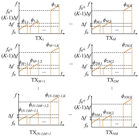
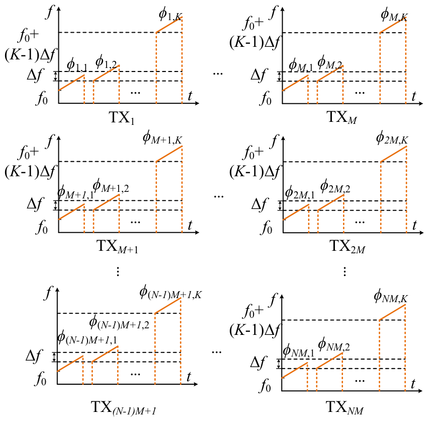
This section introduces the proposed stepped-frequency Doppler-coded integrated joint division multiple access waveform, denoted as SF-DC-JDMA in this paper. The design combines inter-group CDMA coding, intra-group DDMA modulation, and stepped-frequency (SF) synthesis in a unified frame structure for mmWave MIMO radar. As illustrated in Figure 1, transmit channels are organized into multiple Tx groups, and each transmitter follows a chirp sequence with inter-chirp frequency stepping and coding-dependent phase modulation. By jointly exploiting CDMA-based group separation, DDMA-based intra-group Tx identification, and SF bandwidth synthesis across chirps, the proposed waveform enables simultaneous multi-Tx orthogonal transmission, large equivalent bandwidth, and improved range–velocity estimation capability.
Figure 1.
Stepped-frequency Doppler-coded integrated joint division multiple access waveform.
2.1. Doppler-Coded Joint Division Design
We suppose a MIMO radar has multiple () transmitter (Tx) antennas, which can be divided into M groups, with each group containing N Tx antennas. Their orthogonality is achieved by Doppler joint modulation. The M Tx groups are separated by orthogonal CDMA coding sequences, and the N transmitter antennas in each group are modulated using Doppler frequency division multiplexing. For convenience, the n-th Tx of the m-th group is denoted as in this paper. The modulated joint phase on the k-th chirp transmitted by can be written as
where and represent the modulated pseudo random phase of the m-th Tx group and Doppler offset coding phase of the n-th Tx, respectively, for the k-th chirp.
The pseudo random phase is generally designed according to minimized the peak interference residual (PIR) criterion, in order to reduce the Doppler sidelobe caused by interference residual spectrum among Tx groups after decoding [12,16].
Each group of N transmitters is modulated by DDMA. The separation of different transmitting antennas in the Doppler frequency domain is achieved by assigning different Doppler frequency offsets to each antenna. This requires the identification of each Tx in the Doppler dimension. Therefore, non-uniform Doppler division modulation is optimally adopted to distinguish different transmitting antennas within the same group. The non-uniform Doppler offset phase can be represented as
where is an integer greater than 1. Consequently, the Doppler frequency can be divided into sub-bands, with each sub-band equal to .
2.2. SF Signal Model
In millimeter-wave radar, achieving a long unambiguous detection range typically requires a relatively small chirp slope and thus a limited instantaneous bandwidth within a single chirp, which in turn constrains range resolution. In contrast, a pure stepped-frequency waveform synthesizes a much larger effective in-frame bandwidth by introducing frequency steps across successive chirps, thereby significantly improving the range resolution. By combining FMCW chirps with inter-chirp stepped-frequency synthesis, the proposed waveform enables the radar system to simultaneously maintain a long detection range and high range resolution [9,19]. For the k-th chirp, the common dechirp reference, i.e., the mixing local oscillator (LO) signal is
where is the amplitude related to the transmission power, represents the fast time, is the duration of a single chirp signal, represents the frequency modulation slope within a chirp, is the start frequency of the k-th chirp, and t denotes the global time. and are as follows:
where is the start frequency of the first chirp, and represents the frequency step between adjacent chirps.
2.3. Signal Model of Doppler-Coded Joint Division Integrated SF
Doppler-coded joint division can be integrated with the SF waveform to realize simultaneous orthogonal transmission from multiple transmitter antennas, thereby further improving angular resolution. After Doppler joint coding, the analytical expression for k-th chirp signal transmitted by the n-th Tx of the m-th group can be written as
where
and
The total transmit signal over the full frame can be written as
Assuming there are Q targets in the scenario, where the q-th target () is initially located at distance and moves at a constant speed , the distance of target at time is expressed as
Substituting (5) into (10), we obtain
where
Correspondingly, the delay of the echo signal reflected by the q-th target is
where
The received echo signal component transmitted by and reflected by target q can be expressed as
The frame-level echo reflected by the object q can be derived as
After mixing with the LO signal, the intermediate-frequency (IF) signal component corresponding to and object q can be written as
Substituting Equations (4) and (13)–(15) into Equation (18), and grouping the phase terms, the IF signal can be derived as
where
and
It can be observed that and are the first-order terms of fast and slow times, respectively; and correspond to the second-order phase terms of fast and slow times, respectively; and is a constant term unaffected by either fast or slow times. is a hybrid term of fast- and slow-time components, influenced simultaneously by both fast- and slow-time factors. In traffic scenarios, with appropriate waveform parameters, , , and are sufficiently small to be negligible. Subsequently, Equation (19) can be approximated as
The frame-level IF signal can be expressed as
2.4. Mutual Influence of SF Stepping on Intra-Group DDMA Orthogonality in the SF-DC-JDMA Waveform
In the above content, the Doppler-coded joint division design and the SF signal model have been established and integrated into the proposed SF-DC-JDMA waveform. Since both SF stepping and DDMA modulation act on the slow-time dimension, it is necessary to clarify the influence of the SF step size on the orthogonality of DDMA modulation within each Tx group. This subsection analyzes their mutual influence and provides the corresponding joint-design constraints.
As described by Equations (2) and (22), considering the SF step size, the target velocity, and DDMA modulation, the first-order slow-time phase of target q can be expressed as
where , in which , , and are the slow-time frequency shifts induced by stepped-frequency modulation, Doppler, and DDMA modulation within the same Tx group, and can be expressed as
and
Under the conditions that and that the target velocity within one frame remains moderate, the slow-time quadratic term in (23) is negligible compared to the first-order slow-time term. Consequently, the slow-time frequency can be approximately characterized by . For the n-th and -th Tx antennas within the same Tx group, the relative slow-time frequency offset can be expressed as
It can be seen that the relative slow-time frequency shifts between different transmitter antennas remain fixed and are unaffected by stepped-frequency modulation or the Doppler shift. This ensures that the orthogonality of DDMA modulation between different Txs in a group is not impaired.
In summary, SF stepping and DDMA modulation coexist in the slow-time domain through an additive frequency model. Their coupling appears as a common frequency translation, while the DDMA-induced relative separation—and thus, the intra-group transmit orthogonality—remains preserved under the above joint-design constraints. This property provides the theoretical basis for the subsequent signal processing in Section 3.
2.5. Range Resolution and Range Coverage of SF+FMCW+JDMA Versus FMCW+JDMA
In this subsection, the range resolution and chirp-limited unambiguous range of the proposed SF+FMCW+JDMA waveform are compared to those of an FMCW+JDMA waveform without SF. The purpose is to clarify that the resolution improvement of the proposed scheme originates from SF bandwidth synthesis, while JDMA is responsible for multi-Tx orthogonality and the SF+FMCW combination is responsible for simultaneously balancing fine range resolution and long-range coverage.
2.5.1. FMCW+JDMA Without SF
For an FMCW+JDMA waveform without frequency stepping, we let the chirp duration and the chirp slope be and , respectively. The corresponding chirp bandwidth is
Under the maximum usable beat frequency , which is determined by the IF sampling rate (e.g., for complex sampling, or for real sampling), the chirp-limited range coverage is
Meanwhile, the range resolution is determined by the chirp bandwidth and can be rewritten as
Equations (34) and (35) reveal a fundamental trade-off: when and are fixed, increasing the chirp slope improves the range resolution but simultaneously reduces the range coverage . Therefore, a pure FMCW or FMCW+JDMA waveform cannot simultaneously achieve a fine range resolution and long-range coverage.
2.5.2. Proposed SF-DC-JDMA+FMCW
In the proposed SF+FMCW+JDMA waveform, each chirp still adopts the same duration and slope ; hence, the chirp bandwidth and the chirp-limited unambiguous range remain identical to those in (33) and (34). In other words, the range coverage is preserved by keeping a relatively small effective bandwidth within each chirp.
Across consecutive chirps, the carrier frequency is stepped by . For chirps in one frame, the synthesized frame bandwidth used for high-resolution ranging is
The corresponding range resolution becomes
In comparison with this, the resolution is improved by the factor
Therefore, under the same range-coverage constraint (i.e., the same , , and ), SF synthesis increases the frame bandwidth through inter-chirp frequency stepping, and significantly improves the range resolution without reducing range coverage.
It should be noted that SF also introduces a range-dependent slow-time frequency term and, together with target Doppler and DDMA shifts, leads to range–velocity coupling. With the range de-aliasing and range–velocity decoupling procedure described in Section 3, the coupled observations in the fast-time and slow-time domains can be jointly inverted to recover the range and velocity. Hence, the proposed processing chain is an integral part of realizing the resolution-coverage advantage of SF+FMCW+JDMA in practice.
The above analysis leads to a clear role decomposition of the proposed scheme: JDMA (CDMA+DDMA) provides orthogonality among multiple transmitter antennas, while SF+FMCW enables a fine range resolution and long chirp-limited unambiguous range to be achieved simultaneously. The proposed SF-DC-JDMA waveform integrates these two roles into a unified design, and the associated signal processing enables practical range–velocity retrieval under the resulting coupling. Accordingly, the comparison between FMCW+JDMA and SF+FMCW+JDMA under the same range coverage is used to verify the SF contribution to range resolution instead of attributing the resolution gain to JDMA coding alone.
3. Signal Processing
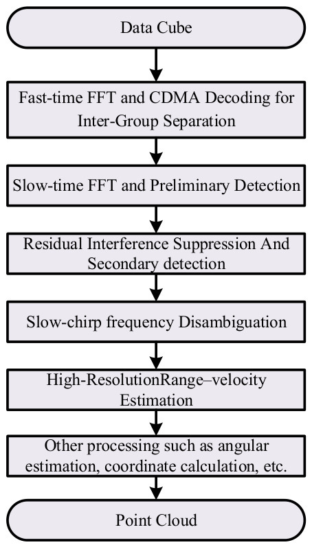
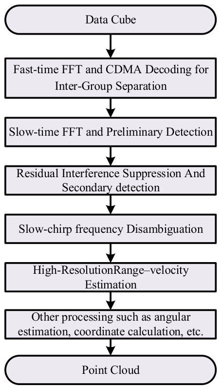
In the previous section, a hybrid waveform combining stepped-frequency and Doppler coding was introduced, and its signal expression was derived. In this section, the corresponding signal processing approach is proposed for this waveform. The overall flowchart of the proposed signal processing scheme is illustrated in Figure 2. First, a range-dimensional FFT is performed on the intermediate-frequency (IF) signal. Then, CDMA decoding is carried out to separate signals from different transmit channels. After that, a Doppler-dimensional FFT is implemented, followed by the removal of residual interference caused by strong targets preliminarily detected. Subsequently, secondary detection is executed, and DDMA ambiguity is resolved. Finally, high-precision range and velocity estimation is achieved. It is worth noting that the focus of this paper is to realize simultaneous orthogonal transmission of multiple transmitter antennas and high-accuracy range–velocity estimation using the proposed waveform; therefore, the angle estimation part is not considered in this work.
Figure 2.
Signal processing flowchart of the proposed waveform.
3.1. Fast-Time FFT and CDMA Decoding for Inter-Group Separation
The fast Fourier transform (FFT) operation is primarily performed on the IF signal, and the resulting fast-time FFT output is expressed as follows
where is the component of TXm,n, and can be written as
where is a constant-phase term. can be expressed as
The last term in (41) is sufficiently small and can be neglected. Moreover, by assuming that the target range remains constant across different chirps within one frame, (41) can be rewritten as follows:
In this result, targets are preliminarily focused at frequency along the fast-time dimension. However, due to the inter-group CDMA coding, the slow-time dimension FFT cannot be applied directly. Instead, inter-group CDMA decoding must be implemented prior to the slow-time FFT to achieve slow-time focusing of signals from each group. After performing the corresponding CDMA decoding for the -th Tx group, the signal is given by
where
It can be seen from the above formula that even after CDMA decoding for the m0-th TX group, residual components from other Tx groups still remain in the signal. These residual signals raise the sidelobes in the Doppler dimension after decoding and degrade target detection performance. Therefore, dedicated residual interference suppression processing is required. This procedure is described in detail in Section 3.3 after following strong-target detection in Section 3.2.
3.2. Slow-Time FFT and Preliminary Detection
Slow-time FFT can be performed on the CDMA-decoded results to enable preliminary target detection. After slow-time FFT, the signal energy is further focused in the Doppler dimension, on which CFAR detection can be applied. Due to DDMA modulation among different Tx channels within one Tx group, the corresponding Tx components are focused at different Doppler positions in the slow-time FFT output. This is equivalent to separating the signals from different Txs. Therefore, it is sufficient to identify the Doppler frequency positions associated with each Tx channel, as detailed in Section 3.4. However, it should be noted that coding residuals induced by strong targets may mask weak-target energy. Therefore, at this stage, only targets with sufficiently a high signal-to-noise ratio (SNR), i.e., those not overwhelmed by residual interference, can be reliably detected. The purpose of detecting these strong targets is to facilitate suppression of the interference residuals they produce, so that weak targets can be recovered in a second-round detection.
3.3. Residual Interference Suppression and Secondary Detection
As shown in (43) and (44), after group-matched CDMA decoding, the desired intra-group components are retained together with a residual term leaked from the other Tx groups. This residual raises the Doppler sidelobes and may mask weak targets. Therefore, a CDMA residual interference suppression algorithm is required. The detailed implementation of residual interference suppression in a waveform jointly modulated by CDMA and DDMA is provided in [16]. Since the residual model in (43) and (44) is expressed through the CDMA/DDMA coding phases and the target slow-time responses, the SF-induced range-dependent slow-time phase is already embedded in these target responses and does not change the algebraic structure of the residual construction. Therefore, the residual interference suppression process is not affected by SF stepping in its procedural form, and the method from [16] can be directly reused in the proposed SF-DC-JDMA framework.
The suppression is implemented as follows. Firstly, strong-target components detected in the first pass, including all N Tx-channel components shifted to different Doppler frequencies by DDMA modulation, are extracted from the 2D-FFT results of each decoded Tx group. Subsequently, the IFFT is performed on these extracted components and corresponding slow-time-domain strong-target signals are reconstructed. Next, according to (44), the residual components are constructed as
Finally, the constructed residuals are specifically subtracted from the decoded slow-time signal of group in (43), and the signal of -th Tx group can be written as
This process is performed iteratively over different Tx groups to progressively remove cross-group coded residuals. Finally, a slow-time FFT is applied again to the residual-suppressed signals, so that Doppler sidelobes are significantly reduced and weak targets previously submerged by residual interference become visible. CFAR detection is then re-executed, and both strong and weak targets can be detected simultaneously.
The purpose of this stage is not to modify the intrinsic SNR of an isolated strong target, but to prevent weak targets from being overwhelmed by the Doppler sidelobes of strong targets, thereby improving the practical detection sensitivity of weak targets in a multi-target scene. In terms of computational cost, the procedure mainly consists of slow-time IFFT/FFT operations, coding-phase multiplications, and point-wise subtractions. No matrix inversion or iterative parameter optimization is required. In practice, strong-target detection and residual cancelation are usually performed only once, which is already sufficient to achieve a clear sidelobe reduction and fully expose weak targets; moreover, the suppression is applied only to range bins containing strong targets, and within each such range bin, the slow-time signals of multiple false-target components are recovered and canceled simultaneously by one IFFT/FFT pair. For one processed range bin, the dominant complexity is in the order of per FFT/IFFT, and the additional burden relative to the baseline 2D-FFT chain remains limited. Since residual suppression is an auxiliary stage of the overall processing chain, a platform-dependent runtime analysis is not further expanded here; the emphasis of this paper remains on the SF joint waveform design and closed-loop range–velocity processing.
3.4. Slow-Time Frequency Disambiguation
After applying FFT to the slow-time signals both before and after interference cancelation, the focused frequency of the target signal is jointly determined by and DDMA modulation. For the n-th DDMA-modulated Txs within each group, the corresponding slow-time frequency offset of target can be expressed as
with
and
where denotes the DDMA-free slow-time frequency shift jointly determined by the stepped-frequency modulation and the range and velocity of target q, and is the extra frequency shift in the n-th Tx in each group caused by DDMA modulation.
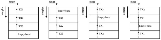
The slow-time frequency offsets corresponding to different Txs can be estimated from the indices of their focused spectral peaks after detection. In order to distinguish different Txs within each group and obtain the slow-time frequency of targets, DDMA disambiguation is performed for both preliminarily detected strong targets and weak targets obtained during the second detection. Due to the non-uniform DDMA modulation strategy within each group, the DDMA frequency offsets among different intra-group Txs follow the sequence corresponding to the DDMA modulation, accompanied by an empty band in the slow-time frequency spectrum. As an illustrative example, we consider one transmitter antenna group containing three Tx channels. Using non-uniform DDMA modulation, these three Tx channels are assigned, in a predefined order, to three of four Doppler sub-bands, leaving one sub-band intentionally empty. Figure 3 summarizes the relationship between the three Tx peak locations and the empty band for all four possible cases. It can be seen that, in every case, the three Tx peaks can be accurately identified based on their relative positions with respect to the empty band. Therefore, different Txs can be easily identified, and the slow-time frequency observations without DDMA shift can be obtained.
Figure 3.
Example of the relationship between intra-group Tx slow-time frequencies and the empty band.
3.5. High-Resolution Range–Velocity Estimation
The slow-time frequency observation is inherently ambiguous because slow-time sampling is performed at the pulse repetition frequency (PRF), which makes the slow-time spectrum periodic with the period PRF. Consequently, the detected slow-time peak corresponds to a wrapped frequency, while the true frequency may differ by an integer multiple of PRF. Therefore, after obtaining the fast-time and slow-time observations, the slow-time frequency must be de-aliased before range–velocity estimation. We let the wrapped slow-time observation of target be . Its unambiguous value is
where is the ambiguity order and . In this work, is obtained by a range-guided branch selection strategy. A baseline is first estimated from the fast-time coarse range:
where , representing the equivalent range span per slow-time ambiguity period; and , denoting the coarse range from the fast-time frequency observation , which is obtained from the index of the detected target peak in the fast-time FFT domain. Then, by using a range-guided boundary offset, the final ambiguity order is selected locally from neighboring branches . If the wrapped observation falls into a boundary-wrapped region, is corrected as , otherwise, . The resulting is then jointly used with for range–velocity decoupling. According to (42) and (48), the range and velocity of target can be derived as
As this work focuses on achieving orthogonal separation of multiple transmit channels via Doppler joint coding, which provides the basis for high-resolution angle estimation, and on combining FMCW and stepped-frequency waveforms to achieve high range resolution, target angle estimation is not further discussed in this article.
4. Experimental Verification
To validate the effectiveness of the proposed waveform and processing scheme, both simulation and real-scene experiments are conducted. In the simulation setup, an FMCW-SF waveform is transmitted by 12 Tx channels with Doppler-domain joint coding for orthogonal separation. The 12 Txs are divided into four groups. Inter-group orthogonality is achieved by CDMA coding, while each group contains three Tx channels and intra-group orthogonality is ensured by DDMA modulation. Simulation parameters are listed in Table 2.
Table 2.
Waveform parameters.
4.1. Verification of Multi-Transmit-Channel Isolation Performance
This part verifies whether the proposed coding strategy can correctly separate signals from different Tx channels and suppress residual inter-group interference.
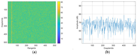
In the simulated scenario with a single point target located at 100 m and moving at 0 m/s, Figure 4 presents the 2D-FFT output of one Tx group and one Rx channel before CDMA decoding. As shown in Figure 4a, the RD spectrum does not exhibit a pronounced target-focused peak and is dominated by distributed spectral components. The corresponding Doppler slice at the target range bin, shown in Figure 4b, also lacks a clear dominant peak. This behavior indicates that, prior to CDMA decoding, signals from different Tx groups remain superimposed in the slow-time domain and cannot be effectively separated. Consequently, inter-group-coded interference elevates the spectral floor and suppresses target visibility. These results confirm that CDMA decoding is a necessary step to isolate different Tx groups and to recover a distinguishable target response in subsequent processing.
Figure 4.
2D-FFT result of one Tx group and one Rx channel without CDMA decoding, containing a single point target: (a) 2D spectrum for one Tx group and one Rx channel; (b) Doppler profile at the target range bin.
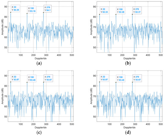
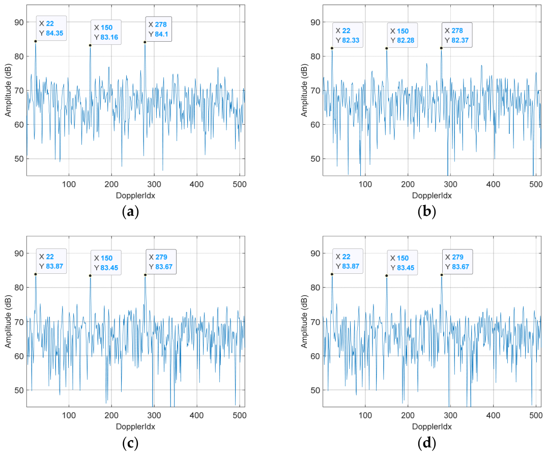
Figure 5 presents the target Doppler profiles after applying group-matched CDMA decoding to each of the four Tx groups. In all four subfigures, three prominent peaks, corresponding to different transmitter antennas within each Tx group, are consistently observed at approximately the same Doppler-bin locations, indicating that the target-related components are successfully recovered after decoding. The consistency of peak positions across Tx groups demonstrates that CDMA decoding effectively suppresses inter-group coded interference and isolates the desired group response. These results verify that the proposed group-wise CDMA processing can reliably reconstruct signals from different transmitter antenna groups, providing a valid basis for subsequent DDMA-based intra-group identification and range–velocity estimation. Within each Tx group, the three Txs are distributed across different Doppler indices according to a predefined coding rule, and can be readily identified and separated.
Figure 5.
Doppler profiles of the target after group-wise CDMA decoding for the four Tx groups: (a) CDMA decoding result for Tx Group 1; (b) CDMA decoding result for Tx Group 2; (c) CDMA decoding result for Tx Group 3; (d) CDMA decoding result for Tx Group 4.
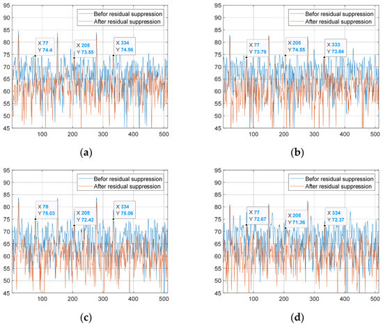
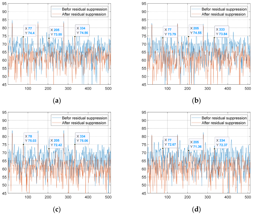
To evaluate the effectiveness of CDMA residual interference suppression across different Tx groups, a simulation scenario with two targets at the same range and velocity was constructed. The two targets have RCS values of 100 m2 and 5 m2. As shown in Figure 6, before suppression, the weak-target responses are masked by the residual interference and the elevated Doppler sidelobes induced by the strong target. In this case, the weak-target peak is comparable to the local interference-plus-noise floor, and its output SINR—defined as the ratio of the weak-target peak power to the local Doppler floor at the same range bin—is lower than 0 dB, which is insufficient for reliable detection. After residual interference suppression, the Doppler sidelobe level is reduced by approximately 6 dB for different Tx groups, and the weak-target output SINR is improved to about 10.04 dB. Since the weak-target peak power is essentially preserved while the local floor is lowered, the previously submerged weak-target peaks become clearly visible and detectable. These results confirm that residual interference suppression not only reduces Doppler sidelobes, but also effectively improves the detection sensitivity of weak targets in the presence of strong-target-coded residuals.
Figure 6.
Comparison of Doppler profiles before and after residual interference suppression for different Tx groups: (a) Tx Group 1; (b) Tx Group 2; (c) Tx Group 3; (d) Tx Group 4.
The simulation results in this subsection verify the effectiveness of Doppler joint modulation in the proposed SF-DC-JDMA waveform for isolating multiple transmit channels. The favorable transmit-channel isolation performance of the proposed waveform establishes a key prerequisite for high-resolution estimation in both azimuth and elevation dimensions.
4.2. Verification of Range and Velocity Estimation Performance
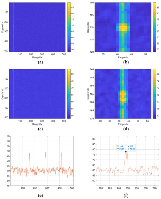
To evaluate the range-resolution contribution of SF in the proposed waveform, two targets are configured with the same velocity (10 m/s) and closely spaced ranges. Under the same Doppler joint coding framework for transmit-channel orthogonality, the detection performance of conventional FMCW and FMCW+SF is compared. For fairness, both simulations adopt the waveform parameters listed in Table 1, except that the inter-chirp frequency stepping is disabled in the conventional FMCW case. Without SF, if the sampling rate and the number of sampling points are kept unchanged, the signal bandwidth has to be reduced to maintain a range coverage of 1247.4 m, which results in a range resolution of only 2.441 m. Based on the same FMCW configuration, when an SF step of 3.125 MHz is further introduced, multiple chirps can synthesize a bandwidth of 1600 MHz. In this way, a range coverage of 1247.4 m and a range resolution of 0.094 m can be achieved simultaneously. Since range resolution is independent of the absolute target range within the coverage, the two closely spaced targets are placed at 100 m and 100.03 m to compare SF-DC-JDMA+FMCW against DC-JDMA+FMCW without SF.
As shown in Figure 7a,b, without SF only one detection is obtained in the RD spectrum, indicating that the two close-range targets are not separable. Using the interpolated range and Doppler bin locations of this single detection, the estimated target state is approximately 100.124 m and 10.018 m/s.
Figure 7.
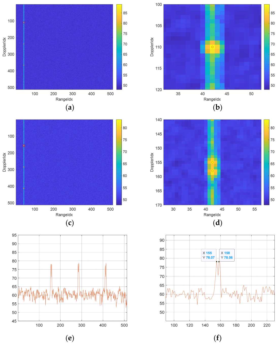
Resolution-performance comparison between the proposed FMCW+SF waveform and conventional FMCW: (a) RD spectrum without SF; (b) zoomed-in RD spectrum without SF; (c) RD spectrum with SF; (d) zoomed-in RD spectrum with SF; (e) Doppler profile with SF; (f) zoomed-in Doppler profile with SF.
In contrast, with SF enabled, two distinct detections are clearly observed, as shown in Figure 7c,d. For the first detection, the interpolated bin locations lead to an estimated range of 100.0019 m and velocity of 10.1817 m/s. For the second detection, the estimated range and velocity are 100.3466 m and 10.1482 m/s, respectively. The Doppler profiles in Figure 7e,f further confirm stable target focusing in the velocity dimension.
Overall, the proposed waveform provides a clear improvement in range resolution and range-estimation accuracy compared with conventional FMCW, while maintaining comparable velocity-estimation performance without noticeable accuracy loss.
4.3. Real-Scene Validation
To further validate the practical sensing performance of the proposed SF-DC-JDMA waveform, field experiments were conducted on the same radar platform and in the same roadside scenario. Although the waveform design and simulation analysis support a range coverage above 1247.4 m, the field-test waveform was configured with a range coverage of 665 m in consideration of the practical power budget of the experimental radar used in this study, so as to ensure reliable detection under real-scene conditions. This range-coverage setting is applied identically to both compared waveforms and therefore does not affect the fairness of the comparison or the validity of the conclusions drawn in this section. Both waveforms were evaluated on the same radar prototype with 12 transmit and 16 receive channels, where the 12 Tx channels are divided into four groups separated by CDMA coding and the three Tx channels within each group are isolated by DDMA modulation. Since this experiment focuses on verifying that the proposed waveform architecture improves range resolution without sacrificing range coverage and remains compatible with existing multi-Tx radar platforms, the detailed antenna-array geometry is not further elaborated. Under this 665 m configuration, two waveform schemes were compared: the baseline CDMA+DDMA-coded FMCW waveform without stepped-frequency modulation (denoted as DC-JDMA+FMCW), and the proposed SF-DC-JDMA waveform. The purpose of this section is not only to show a denser point cloud but also to demonstrate, through system-configuration details, range-segmented detection statistics, and multi-frame track association, that the additional points mainly correspond to valid target echoes rather than noise or sidelobe leakage.
4.3.1. Experimental Configuration
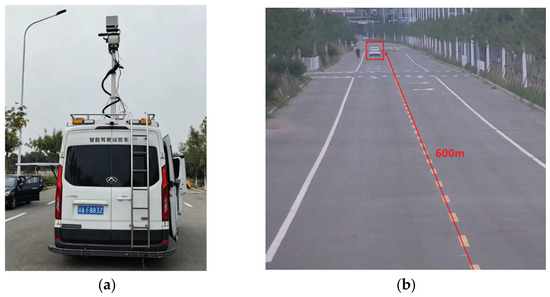
The radar was mounted on the mast of a test vehicle parked at a fixed location and oriented toward the driving lane, as shown in Figure 8a. Figure 8b shows the field-test road scene, including the vehicle motion path and the main testing range of about 600 m.
Figure 8.
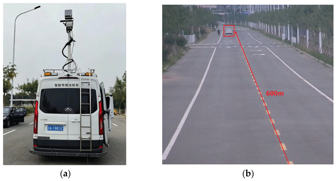
Field-test scene: (a) photograph of the radar installation on a vehicle parked at a fixed location; (b) photograph of the road scene with the target vehicle and the 600 m testing range.
The detailed experimental parameters are summarized in Table 3. Unless otherwise specified, the two waveforms were configured with the same center frequency, chirp duration, pulse repetition interval, sampling rate, Tx/Rx channel numbers, CDMA grouping, DDMA frequency-shift assignment, transmit power, detection threshold, and point-cloud post-processing parameters. The only intentional difference is that frequency stepping is enabled in SF-DC-JDMA and disabled in DC-JDMA+FMCW, so that the comparison is performed under the same chirp-limited range-coverage constraint of about 665 m.
Table 3.
Field-experiment parameters of DC-JDMA+FMCW and SF-DC-JDMA.
4.3.2. Track Association for Point Validity Assessment
Since a denser point cloud alone cannot exclude the possibility of noise or sidelobe-induced false detections, the detected points are further associated with multi-frame tracks. In this experiment, CFAR detection is first performed on each frame to obtain the raw point cloud. For an existing track, candidate points in the current frame are then selected within a range-Doppler-angle gate centered at the one-step prediction of the track state. Among the gated candidates, the point with the minimum normalized distance to the predicted state is associated with the track; if no candidate falls inside the gate, the track is marked as coasted for the current frame. A track is confirmed only when it is continuously associated over no fewer than frames and satisfies a basic motion-consistency check, and it is deleted after consecutive missed associations. Points associated with a confirmed track are counted as track-associated points, whereas the remaining isolated points are counted as unassociated points. Random noise and most sidelobe detections generally lack temporal continuity across frames and therefore can hardly satisfy the confirmation and motion-consistency conditions in a sustained manner. Consequently, the track–association ratio is used as a practical indicator of point validity.
4.3.3. Multi-Frame Point-Cloud and Track Results
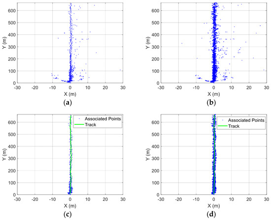
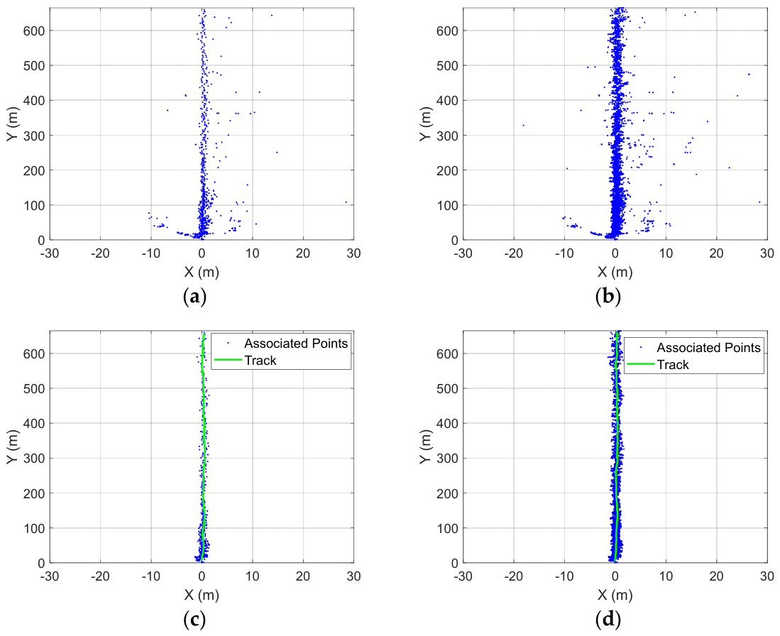
Figure 9 shows representative multi-frame superimposed point clouds and the corresponding confirmed tracks for the two waveforms in the same scene. For clarity, only moving-target detections are retained, while static-target points are removed. Figure 9a,b present the multi-frame moving-target point clouds of DC-JDMA+FMCW and SF-DC-JDMA, respectively, while Figure 9c,d show the corresponding track-associated points together with the confirmed tracks. It can be observed that SF-DC-JDMA yields a denser moving-target point cloud and more continuous track-associated points than DC-JDMA+FMCW under the same range-coverage configuration.
Figure 9.
Multi-frame moving-target point-cloud and track comparison between DC-JDMA+FMCW and SF-DC-JDMA under the same approximately 665 m range-coverage design: (a) multi-frame moving-target point cloud of DC-JDMA+FMCW; (b) multi-frame moving-target point cloud of SF-DC-JDMA; (c) track-associated points and confirmed track of DC-JDMA+FMCW; (d) track-associated points and confirmed track of SF-DC-JDMA. Blue points denote moving-target detections or track-associated points, and the green curve denotes the confirmed track.
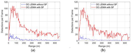
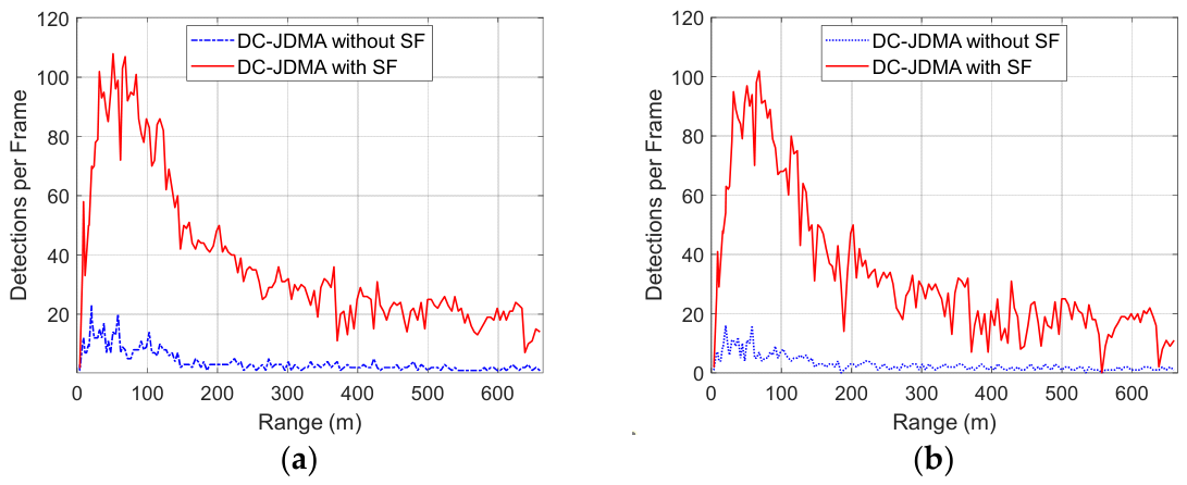
Figure 10 compares the range-dependent detection statistics of DC-JDMA without SF and DC-JDMA with SF under the same field-test conditions. Figure 10a shows the average number of total detections per frame as a function of range, while Figure 10b shows the corresponding number of track-associated detections per frame. Across the entire tested range, the SF-enabled waveform yields substantially more detections than the waveform without SF. More importantly, the associated-detection curve in Figure 10b closely follows the total-detection curve in Figure 10a, indicating that the additional points obtained by SF-DC-JDMA are mainly associated with confirmed stable tracks rather than appearing as isolated false detections. These results further confirm that, under the same range-coverage constraint, the proposed SF-DC-JDMA waveform improves the density of valid target points in practical traffic sensing.
Figure 10.
Comparison of per-frame detection counts versus range for DC-JDMA without SF and DC-JDMA with SF: (a) total detections; (b) track-associated detections.
4.3.4. Range-Segmented Statistical Comparison
Because the number of detection points varies with range, the statistics are computed over multiple range segments. For each waveform and each range segment, we count:
- The average total number of detection points per frame, ;
- The average number of track-associated points per frame, ;
- The track–association ratio, which is given as:
The results are summarized in Table 4.
Table 4.
Range-segmented point-cloud statistics of DC-JDMA+FMCW and SF-DC-JDMA.
4.3.5. Discussion of the Field Results
As shown in Figure 9, the proposed SF-DC-JDMA waveform produces a visibly denser point cloud than DC-JDMA+FMCW on the same test vehicle and along the same road structures. This observation is further supported by the range-dependent statistics in Figure 10. Across the entire tested range, both the total detections per frame in Figure 10a and the track-associated detections per frame in Figure 10b of SF-DC-JDMA remain substantially higher than those of DC-JDMA without SF. Moreover, the associated-detection curve closely follows the total-detection curve, indicating that the additional points are mainly linked to confirmed stable tracks rather than appearing as isolated outliers. Consistent with Table 4, the increase is concentrated in track-associated points, whereas the number of unassociated isolated points does not increase significantly. Since unassociated points are more likely to originate from random noise or unstable sidelobe detections, these results support the conclusion that the denser point cloud of SF-DC-JDMA mainly comes from an increased number of valid target-echo points, rather than from false detections.
In addition, under the same approximately 665 m range-coverage constraint, SF-DC-JDMA benefits from inter-chirp frequency stepping and therefore provides a finer effective range resolution than DC-JDMA+FMCW. This finer range sampling contributes to richer scattering centers on extended targets, such as vehicles, which is consistent with the denser track-associated point cloud in Figure 9 and the persistently higher associated-detection counts over range in Figure 10.
5. Discussion
The proposed SF-DC-JDMA waveform is motivated by a practical trade-off that is widely recognized in radar remote sensing: achieving a high angular resolution through multi-Tx MIMO signaling while simultaneously maintaining a high range resolution and extended detection range. Existing studies typically optimize one part of this trade-off, e.g., orthogonal multi-Tx coding (TDM/CDMA/DDMA) or synthesized wide-band ranging (stepped-frequency schemes), but they less often address both in a unified waveform-design and processing framework. The present results indicate that integrating stepped-frequency synthesis with Doppler-domain joint coding can effectively bridge this gap.
From the perspective of the working hypotheses, the findings support the two central assumptions of this work. First, inter-group CDMA and intra-group DDMA remain effective for TX separation after introducing stepped-frequency modulation, as reflected by the consistent recovery of group-specific Doppler components. Second, adding SF to the FMCW framework improves range discrimination without causing a substantial loss of velocity-estimation usability. In the two-target close-spacing case, the SF-enabled scheme resolves targets that are not separable under conventional FMCW settings, while velocity estimates remain stable and physically consistent. This behavior is aligned with the model-based expectation that SF increases effective in-frame bandwidth and therefore improves range resolution.
In a broader remote sensing context, this integration strategy is relevant beyond automotive traffic scenes. Many short-to-medium-range sensing tasks—such as roadside monitoring, infrastructure observation, perimeter surveillance, and low-altitude platform sensing—face similar requirements: multi-target separation, robust channel orthogonality, and accurate range–velocity retrieval under a limited time frame. The proposed framework suggests a general design principle for such systems: maintain coding-domain separability for multi-channel observations while using inter-chirp frequency synthesis to enhance spatial/range discrimination.
At the same time, several limitations should be acknowledged. The current validation mainly focuses on controlled simulation settings and representative field measurements; broader environmental diversity (dense multipath, severe clutter, high-dynamic targets, and stronger non-ideal hardware effects) should be investigated further. In addition, the current ambiguity-resolution strategy is locally branch-guided and works well in practical operating regimes, but more global and adaptive strategies may be needed when velocity ambiguity spans multiple PRF periods. Computational load and real-time implementation constraints also remain important for deployment-scale systems.
Future research can proceed along four directions.
(1) Robust ambiguity handling by extending branch selection to multi-hypothesis global optimization under strong dynamics.
(2) Joint calibration and suppression by incorporating hardware phase/amplitude calibration with residual-interference suppression in a unified estimator.
(3) End-to-end multi-dimensional estimation by jointly optimizing coding, waveform, and processing for range–velocity-angle consistency.
(4) Cross-scenario remote sensing validation by evaluating the method on larger real-world datasets across weather, traffic density, and sensing geometry conditions.
Overall, the results suggest that SF-DC-JDMA provides a practically meaningful pathway for next-generation mmWave remote sensing systems that require both multi-channel orthogonality and high-precision range–velocity perception.
6. Conclusions
In this article, a novel waveform framework, termed stepped-frequency Doppler-coded integrated joint division multiple access (SF-DC-JDMA), is proposed for mmWave MIMO radar. The core idea is to integrate hybrid CDMA–DDMA coding, which provides orthogonal separation among multiple transmit channels, with an FMCW plus stepped-frequency waveform, which supports a high range resolution and extended range capability. Based on this integrated waveform design, a complete signal processing architecture is further developed, including decoding, spectral processing, ambiguity handling, residual-interference suppression, and range–velocity estimation. Simulation results show that the proposed framework can separate multi-Tx components, reduce residual Doppler sidelobes by approximately 6 dB, and resolve two targets separated by 0.3 m at around 100 m, whereas the conventional FMCW configuration produces only one detection. Real-scene measurements further demonstrate that the proposed waveform produces denser point-cloud representations of traffic targets. These results validate that SF-DC-JDMA can jointly support a long detection range, high range resolution, and multi-Tx orthogonality, thereby providing a practical foundation for high-angular-resolution radar sensing in automotive and traffic scenarios.
Author Contributions
Conceptualization, J.L.; methodology, J.L.; software, J.L.; validation, J.L.; formal analysis, J.L.; investigation, J.L.; resources, J.L.; data curation, J.L.; writing—original draft preparation, J.L.; writing—review and editing, J.L., C.W., X.R., L.J. and Z.W.; visualization, J.L.; supervision, Z.W.; project administration, Z.W.; funding acquisition, Z.W. All authors have read and agreed to the published version of the manuscript.
Funding
This research received no external funding.
Data Availability Statement
The data presented in this study are available on request from the corresponding author. The data are not publicly available due to privacy.
Conflicts of Interest
The authors declare no conflicts of interest.
Abbreviations
The following abbreviations are used in this manuscript:
| CDMA | Code Division Multiple Access |
| DDMA | Doppler Division Multiple Access |
| TDMA | Time Division Multiple Access |
| FMCW | Frequency-Modulated Continuous Wave |
| SF | Stepped Frequency |
| FOV | Field of View |
| MIMO | Multiple-Input Multiple-Output |
| SF-DC-JDMA | Stepped-Frequency Doppler-Coded Integrated Joint Division Multiple Access |
References
- Petrov, N.; Kumbul, U.; Vaucher, C.; Yarovoy, A. Phase modulated FMCW waveforms and receiver structures for automotive MIMO radars. In Proceedings of the 2023 IEEE International Radar Conference (RADAR), Sydney, Australia, 1–5 May 2023; pp. 1–6. [Google Scholar]
- Romeh, M.A.; Moustafa, K.H.; Ahmed, F.M.; Mehany, W. Detection performance analysis of mimo radar dual channels lfm and nlfm waveforms in the presence of clutter. In Proceedings of the 2024 6th Novel Intelligent and Leading Emerging Sciences Conference (NILES), Cairo, Egypt, 19–21 October 2024; pp. 223–227. [Google Scholar]
- Sichani, N.; Ahmadi, M.; Raei, E.; Alaee-Kerahroodi, M.; Ojaroudi, M.; Nayebi, M.M. Waveform selection for FMCW and PMCW 4D-imaging automotive radar sensors. In Proceedings of the 2023 IEEE Radar Conference (RadarConf23), San Antonio, TX, USA, 1–5 May 2023; pp. 1–6. [Google Scholar]
- Mazher, K.U.; Graff, A.; Gonzalez-Prelcic, N.; Heath, R.W. Automotive radar interference characterization: FMCW or PMCW? In Proceedings of the ICASSP 2024—2024 IEEE International Conference on Acoustics, Speech and Signal Processing (ICASSP), Seoul, Republic of Korea, 14–19 April 2024; pp. 13406–13410. [Google Scholar]
- Fan, L.; Wang, J.; Chang, Y.; Li, Y.; Wang, Y.; Cao, D. 4D mmWave radar for autonomous driving perception: A comprehensive survey. IEEE Trans. Intell. Veh. 2024, 9, 4606–4620. [Google Scholar] [CrossRef] [Scilit]
- Xu, L.; Sun, S.; Mishra, K.V.; Zhang, Y.D. Automotive FMCW radar with difference co-chirps. IEEE Trans. Aerosp. Electron. Syst. 2023, 59, 8145–8165. [Google Scholar] [CrossRef] [Scilit]
- Kahlert, M.; Fei, T.; Tebruegge, C.; Gardill, M. An improved stepped-frequency PMCW waveform for automotive radar applications. In Proceedings of the 2024 15th German Microwave Conference (GeMiC), Duisburg, Germany, 11–13 March 2024; pp. 193–196. [Google Scholar]
- Cheng, H.; Lou, W. Pd-fmcw: Push the limit of device-free acoustic sensing using phase difference in fmcw. IEEE Trans. Mob. Comput. 2023, 22, 4865–4880. [Google Scholar] [CrossRef] [Scilit]
- Sun, S.; Shi, C.; Huang, L.; Chen, J.; Zhang, R. An optimizing method for fmcw chirp linearity based on continuous frequency step analysis. In Proceedings of the 2025 IEEE Wireless and Microwave Technology Conference (WAMICON), Cocoa Beach, FL, USA, 14–15 April 2025; pp. 1–4. [Google Scholar]
- Matsuda, T.; Hashiguchi, H. Ddma-mimo observations with the mu radar: Validation by measuring a beam broadening effect. IEEE J. Sel. Top. Appl. Earth Obs. Remote Sens. 2023, 16, 3083–3091. [Google Scholar] [CrossRef] [Scilit]
- Matsuda, T.; Nishimura, K.; Hashiguchi, H. Integrating ddma and cdma mimo radar functionalities into simo systems: A case study with the mu radar. IEICE Trans. Commun. 2025, E108-B, 891–901. [Google Scholar] [CrossRef] [Scilit]
- Nagesh, S.; Gonzalez-Huici, M.; Bathelt, A.; Heredia Conde, M. Sequence optimisation for compressed sensing CDMA MIMO radar via mutual coherence minimisation. IET Radar Sonar Navig. 2024, 18, 2072–2087. [Google Scholar] [CrossRef] [Scilit]
- Romeh, M.A.; Moustafa, K.H.; Ahmed, F.M.; Mehany, W. Performance evaluation of ddma mimo radar detection in the presence of correlated clutter. In Proceedings of the 2024 International Telecommunications Conference (ITC-Egypt), Cairo, Egypt, 22–25 July 2024; pp. 590–595. [Google Scholar]
- Hassanien, A.; Aboutanios, E. Resolving target ambiguities in automotive radar using DDMA techniques. In Proceedings of the 2023 IEEE International Radar Conference (RADAR), San Antonio, TX, USA, 1–5 May 2023; pp. 1–6. [Google Scholar]
- Hong, W.; Shen, S.; Zhang, Y.; Zhou, J. Multiple subbands coherent accumulation target detection algorithm for ddma-mimo radar. IEEE Trans. Intell. Transp. Syst. 2024, 25, 11485–11496. [Google Scholar] [CrossRef] [Scilit]
- Wang, Y.; Pei, Q.; Hu, X.; Long, J.; Yu, H.; Zheng, L. Doppler-coded joint division multiple access waveform for automotive mimo radar. In Proceedings of the ICASSP 2023—2023 IEEE International Conference on Acoustics, Speech and Signal Processing (ICASSP), Rhodes Island, Greece, 4–10 June 2023; pp. 1–5. [Google Scholar]
- Kahlert, M.; Fei, T.; Tebruegge, C.; Gardill, M. Stepped-frequency PMCW-radar modulation scheme for automotive applications. In Proceedings of the 2024 IEEE Topical Conference on Wireless Sensors and Sensor Networks (WiSNeT), San Antonio, TX, USA, 21–24 January 2024; pp. 30–33. [Google Scholar]
- Kahlert, M.; Fei, T.; Tebruegge, C.; Gardill, M. Stepped-frequency PMCW waveforms for automotive radar applications. IEEE Trans. Radar Syst. 2025, 3, 233–245. [Google Scholar] [CrossRef] [Scilit]
- Gao, Y.; Wei, W.; Yu, X.; Cui, G. High-resolution detection of moving targets using stepped-frequency signal for mmwave fmcw radar. In Proceedings of the 2024 IEEE International Conference on Signal, Information and Data Processing (ICSIDP), Zhuhai, China, 22–24 November 2024; pp. 1–6. [Google Scholar]
- Petrov, N. Range-Doppler circulating LFM for automotive MIMO radars. In Proceedings of the 2023 20th European Radar Conference (EuRAD), Berlin, Germany, 20–22 September 2023; pp. 169–172. [Google Scholar]
- Li, J.; Zhang, F.; Xu, Z.; Pan, S. Frequency-domain adaptive processing with stepped-frequency radar for deceptive jamming suppression. IEEE Signal Process. Lett. 2026, 33, 1561–1565. [Google Scholar] [CrossRef] [Scilit]
- Wang, Z.; Xu, W.; Lu, S.; Liang, C.; Zheng, L.; Hu, X. Analysis on anti-interference performance of random stepped-frequency waveform for automotive radar. In Proceedings of the 2024 IEEE International Conference on Signal, Information and Data Processing (ICSIDP), Zhuhai, China, 22–24 November 2024; pp. 1–6. [Google Scholar]
- Zhu, S.; Wu, X.; Zhang, C.; Shi, Z.; Zhang, A.; Wang, L.; Liu, C. Design of ultra wideband ground penetrating radar transceiver based on stepped frequency continuous wave. In Proceedings of the 2025 International Applied Computational Electromagnetics Society Symposium (ACES-China), Huangshan, China, 8–11 August 2025; pp. 1–3. [Google Scholar]

Disclaimer/Publisher’s Note: The statements, opinions and data contained in all publications are solely those of the individual author(s) and contributor(s) and not of MDPI and/or the editor(s). MDPI and/or the editor(s) disclaim responsibility for any injury to people or property resulting from any ideas, methods, instructions or products referred to in the content. |
© 2026 by the authors. Licensee MDPI, Basel, Switzerland. This article is an open access article distributed under the terms and conditions of the Creative Commons Attribution (CC BY) license.