


Abstract
Growing pressure to reduce the environmental impact of manufacturing has increased interest in electrical discharge machining (EDM) variants that limit liquid dielectric consumption. This study investigates near-dry EDM of Inconel 625 and Titanium Grade 2 using CO2 supplied to the machining gap. A modified central composite design comprising 25 experiments per material evaluated pulse duration, voltage, discharge current, and gas pressure over ranges of 100–500 µs, 80–120 V, 0.9–4.5 A, and 2–10 bar, respectively. Results were analysed for the material–polarity configurations Cu working electrode (+)/Inconel 625(−) and Cu working electrode(−)/Titanium Grade 2(+), reflecting their combined effects. The volumetric material-removal-rate models showed the strongest statistical performance, with values for ln(Vv) of 0.968 and 0.940, respectively, and captured the dominant response trends. Their comparatively strong statistical performance may be attributed to the integral nature of material removal, which partially averages stochastic variability among discharges. Roughness and electrode response were more sensitive to local crater formation and redeposition. Recast-layer and heat-affected-zone characteristics were interpreted in relation to thermophysical properties, microstructure, and polarity.
1. Introduction
Electro-discharge machining is a thermal process where the material is removed by electrical erosion, occurring as a result of phenomena accompanying pulsed electrical discharges, between the working electrode and the workpiece, separated by a dielectric in the machining gap [1]. As a result of interaction with the plasma channel (which occurs in the machining gap), the workpiece material is melted and evaporated. All the solidified particles are removed from the gap by the forced dielectric flow [2,3]. Furthermore, the dielectric also dissipates the heat from the working electrode and machined material. The complex physical phenomena occurring during the process result in specific properties of the surface layer. According to Hayakawa et al. [4], the rapid thermal changes during the process result in structural changes in the surface layer of the workpiece such as microcracks, associated with the presence of residual stresses, surface porosity, grain boundary growth and, finally, changes in the chemical composition.
Dielectrics which are used during the EDM process can be divided into two groups: liquid and gaseous. Among the liquid dielectrics, the most commonly used are water-based dielectrics and carbon-based dielectric liquids [2]. Chakraborty et al. [5] point out that carbon-based dielectrics are characterised by low viscosity, which improves flushing of the machining area, low ignition level, low vaporisation heat and generated vapours (i.e., CO and CH4), which are harmful to the environment and machine operator. Zhang et al. [6] point out that the vapours formed during the discharge, consisting of polycyclic aromatic hydrocarbons, benzene, mineral aerosols and other by-products, diffuse deep into the white layer, forming carbide inclusions (Fe3C) in the case of steel processing. This affects subsequent technological operations and, in particular, during heat treatment, carburisation of the surface layer increases and numerous of microcracks propagate along the grain boundaries.
Water-based dialectics (such as deionised water and also mixtures with glycerine, ethylene glycol, polyethylene glycol, glucose or sucrose) are characterised by higher thermal stability (eight times higher evaporation energy, lower boiling point) than carbon-based dielectrics, which enables them to reach higher discharge energy [2]. Zhang et al. [6] underline that EDM in water-based dielectrics is characterised by higher productivity and lower working electrode wear (especially for high discharge energies); however, at the same time lower shaping accuracy (comparing to carbon-based dielectrics) is achieved. Surface roughness is improved and less microcracks are observed in the surface layer. Studies presented in [2] showed significant differences in austenitic steel integrity after the EDM process in carbon-based and water-based dielectric liquids. It was stated that lower roughness and hardness of the surface was obtained by using deionised water as a dielectric liquid. Furthermore, Kibria et al. [7] highlight that additional heat treatment does not result in further propagation of microcracks, but oxidation of the material is observed. Moreover, the properties of water-based dielectrics are difficult to stabilise (losing insulating properties over time), which is why they are used most often in EDM cutting (fire risk reduction).
The group referred to as gaseous dielectrics includes gases such as oxygen, argon, nitrogen, air, or mixtures of two gases. In dry EDM, a process which involves machining in a gaseous environment, the melted workpiece material is removed from the machining gap by the gas flow delivered to the machining gap under dedicated pressure through a channel in the working electrode [8]. The primary function of the gaseous dielectric during dry EDM is cooling, solidification, and removal of the molten material from the machining zone. This is crucial to avoid by-products which occur during the machining from melting into the workpiece and working electrode. Furthermore, the gas jet enables the plasma channel to be extinguished among the discharges, which enables the rebuilding of proper parameters of the gaseous dielectric and allows the initiation of the next discharge. The authors in [8] underline substantial differences between thermal characteristics of EDM in liquid dielectrics and in gaseous ones. It is thought that machining in a liquid environment is a strictly thermal process, while dry EDM is a thermochemical process where additional chemical reactions may occur. According to Tao et al. [9], appropriate selection of process parameters and type of gaseous dielectric is crucial to gain appropriate machining efficiency in roughing operations and high accuracy in finishing operations. Another key factor based on Roth et al. [10] which has to be taken into account during dry EDM is the type of working material, which directly affects process stability and efficiency. This is due not only to its physical properties but also to characteristics that directly impact the nature of the discharges that occur during the process. Baroi et al. [11] underline that dry EDM limits the production of pollutants compared to machining in carbon-based dielectrics. However, by-products from the machining process can still continue to spread into the environment, posing a potential danger to the machine operator. It is therefore necessary to use appropriate extraction methods and personal protective equipment.
The dry EDM process modifications—known as hybridisation, with the usage of a mixture of liquid and gas during EDM—are also described in the literature [9,12,13,14,15]. This machining variant is called near-dry EDM. To improve machining efficiency, reduce the amount of melted erosion products embedded on the machined surface and achieve lower surface roughness compared to EDM in gaseous dielectric, Kao et al. [12] used a mixture of water and oxygen. A similar strategy was used by Tao et al. [14] during the EDM milling process, which made it possible to obtain a mirror-like surface.
Both dry EDM and near-dry EDM are perceived as environmentally friendly variants of the electro-discharge machining process (especially when chemically inert deionised water is used as a liquid medium). Singh et al. [13] provided an overview of the concept of “green EDM” as a response to increased environmental restrictions. In 2019, the European Green Deal [16] for the European Union (EU) was established. The main aim of that approach is advocacy for sustainable development of industry—the transformation into a modern, resource-efficient and competitive economy where there will be no net emissions of greenhouse gases by 2050 and economic growth will be decoupled from resource use [16].
It still seems that dry EDM and near-dry EDM methods need to be investigated to deeply understand the principles of the process and select proper process parameters to ensure machining stability and efficiency, as well as to demonstrate the benefits of this solution. The main aim of this study was to investigate how the properties of the workpiece material affect near-dry EDM performance. Particular attention was given to the thermal characteristics of the investigated materials (Inconel 625 and Titanium Grade 2), described using the Palatnik criterion, which combines specific heat capacity, density, thermal conductivity, and melting temperature. This made it possible to relate the thermal behaviour of the materials to their response during electro-erosive machining. The analysis also took into account the stochastic nature of electrical discharges, which may contribute to the scatter observed in the experimental results and complicate the direct interpretation of the influence of material properties on process performance. The preliminary research results of EDM in a gaseous environment were presented in [17,18,19,20]. During this study, the near dry-EDM milling in carbon dioxide with external workpiece cooling with deionised water of Inconel 625 and Titanium Grade 2 were investigated.
2. Materials and Methods
2.1. Test Stand and Samples
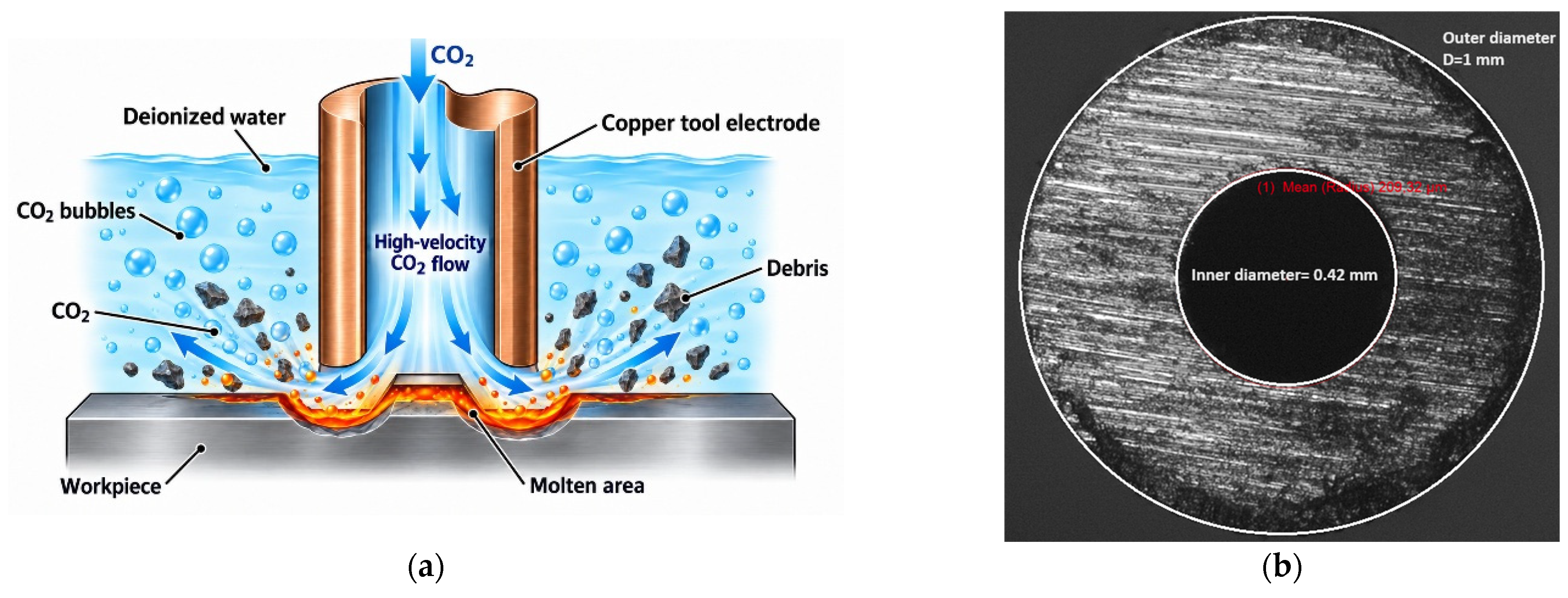
Near-dry EDM in the milling kinematics was conducted on the research test stand (Figure 1) equipped with electro-discharge generator MATRIX MPS-7163 120V/5.1A [20]. The test stand was expanded with the gaseous supply system to enable machining in gaseous dielectric. Carbon dioxide, which was the gaseous dielectric, was supplied under pressure to the machining gap (Figure 2a) through a thin-walled tubular electrode (Figure 2b). Additionally, the workpiece was submerged in the deionised water to ensure proper heat dissipation from the machining area. In this configuration, only gas was delivered through the electrode, whereas conventional mist-based near-dry EDM employs a gas–liquid mist introduced through the electrode. An overflow maintained the water level at 3 mm above the initial workpiece surface. Water was recirculated through a large-capacity reservoir, pump, and filtration system to remove heat and stabilise the bulk water temperature. The water temperature was stable, 22 °C, controlled with thermometer. CO2 supply pressure was set at the cylinder regulator for each experimental condition, and gas flow was maintained at 5 L/min throughout all experiments using a flowmeter. The interelectrode gap was regulated by the machine’s software-controlled Z-axis feed in response to the electrical conditions of the process. The initial gap setting (100 µm) and gap-control settings were unchanged between the compared configurations.
Inconel 625 alloy machining was carried out with the reversed polarity—working electrode (+) and workpiece (−). The electrode polarity was established during preliminary tests, in which machining stability and tool-electrode wear were evaluated for Inconel 625 and Grade 2 titanium. The assessment included machining stability, the occurrence of short circuits and arcing, repeatability, material-removal performance, and tool wear. When using simple polarisation, the machining performance was very low, with very high working electrode wear. On this basis, it was concluded that with the used voltage generator, conducting stable EDM of Inconel 625 alloy is only possible if reverse polarity is used. The proposed approach also coincides with that proposed in the previous experiments reported in [19,20,21] and also reported by Talla et al. [22]. Li et al. [23] discussed polarity-dependent energy transfer and the adhesion of eroded particles as possible factors contributing to the low relative tool wear in dry EDM. In particular, they proposed that particles adhering to the tool surface could provide protection against erosion. However, greater energy transfer to an anodic surface does not, by itself, establish a reduction in tool wear. The proposed protective effect of deposited particles should therefore be distinguished from energy-partition effects and is considered here as a literature-based hypothesis rather than a mechanism verified under the present machining conditions. Torres et al. [24] have shown that during EDM of Inconel 600, electrode polarity has an influence on machining performance. Under positive polarity, electrode wear initially increased with current up to approximately 7 A and then decreased. In some cases, negative values of electrode wear were observed, suggesting that carbonaceous and graphite particles were redeposited and resolidified on the tool surface during machining. In contrast, negative polarity was associated with a more pronounced accumulation of carbonaceous material on the electrode surface and higher tool wear. The authors also reported that positive polarity contributed to reduction in surface roughness and was therefore more suitable for finishing conditions where surface quality was a priority. The available literature on dry EDM of Inconel 625 in carbon dioxide is still very limited. Therefore, the polarity configuration reported in the existing studies should be interpreted as effective under the specific experimental conditions considered rather than as a universal requirement for machining Inconel 625 in gaseous dielectrics.
For Titanium Grade 2, stable and effective machining was obtained when the simple polarity was used—working electrode (−) and machined workpiece (+). This polarity configuration is consistent with previous studies on pure Titanium Grade 2, where a negatively polarised tool electrode was successfully applied during EDM and micro-EDM. Previous studies on pure titanium and titanium alloys have also reported that cathodic tool polarity can be required for productive EDM [25,26,27,28,29,30]. Shen et al. [26] observed behaviour which could be related to the distribution of discharge energy between the electrodes. With the workpiece acting as the anode, electron bombardment promotes intensive local heating of its surface. This effect is particularly important for Titanium Grade 2 because of its relatively low thermal conductivity, which limits heat dissipation from the discharge zone and favours local melting and material removal. Holsten et al. [31] presented mechanisms associated with TiC formation during sinking EDM. Klocke et al. [25] also reported that in continuous-discharge EDM of Ti6Al4V, the material-removal rate is markedly reduced when the tool electrode is positively polarised. This behaviour has been attributed to the formation of a TiC-rich subsurface layer, which increases the resistance of the material to further electro-erosive removal. Anodic tool polarity was also associated with the formation of a thicker heat-affected zone. This can be explained by a lower thermal load at the workpiece surface, sufficient to induce melting and solid-state transformations, but insufficient to promote substantial material evaporation.
Polarity was therefore a material-specific machining condition and was not independently varied in the subsequent experimental design.
Figure 1.
Test stand scheme (on the basis of [32]).
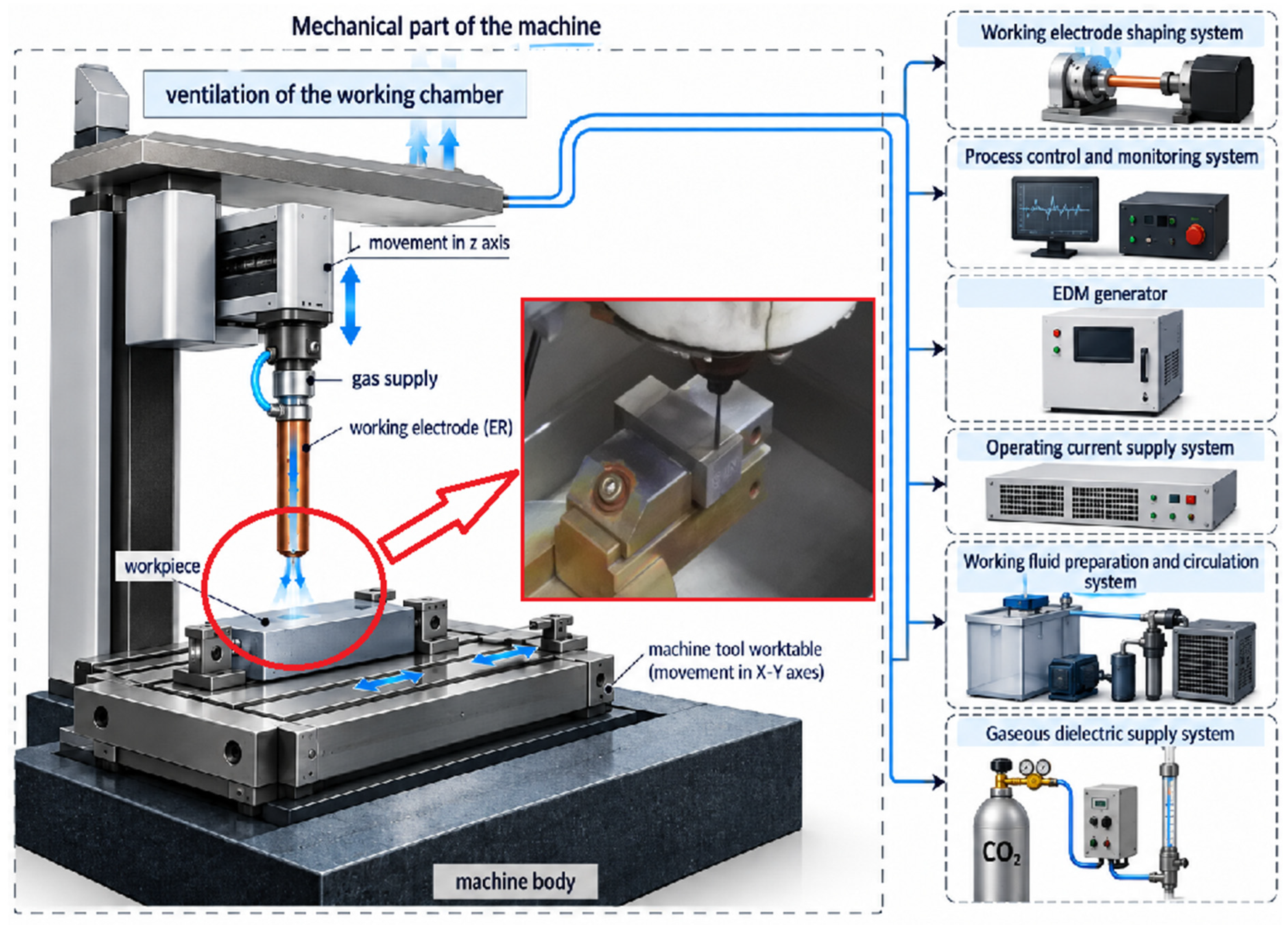
Figure 2.
(a) Scheme of near-dry EDM milling in CO2 with external workpiece cooling; (b) working electrode cross-section: inner diameter 0.42 mm, outer diameter 1 mm [21].
The tests were carried out on rectangular specimens made of Inconel 625 and Titanium Grade 2 with dimensions of 40.6 × 15.0 × 12.1 mm. The specimens made of Inconel were annealed at 980 °C for 30 min, cooled with water, while specimens made from Grade 2 titanium as supplied (the chemical composition of the materials is shown in Table 1) were grounded and polished with two flat-parallel surfaces.
Table 1.
Chemical composition of (a) Inconel 625 alloy samples and (b) Titanium Grade 2 samples (based on a certificate provided by the manufacturer).
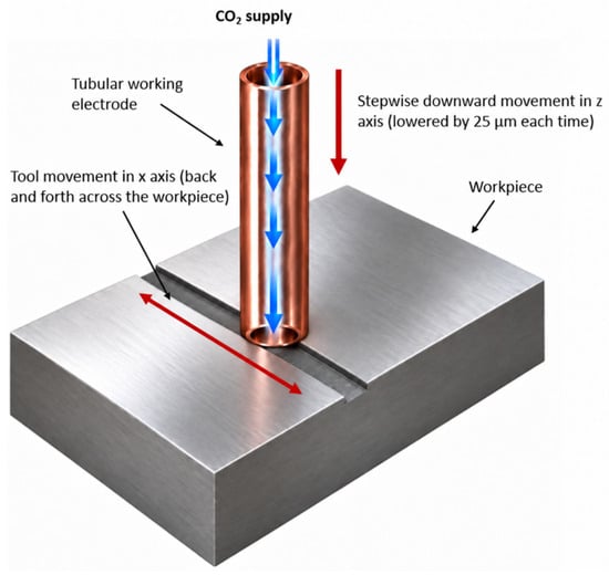
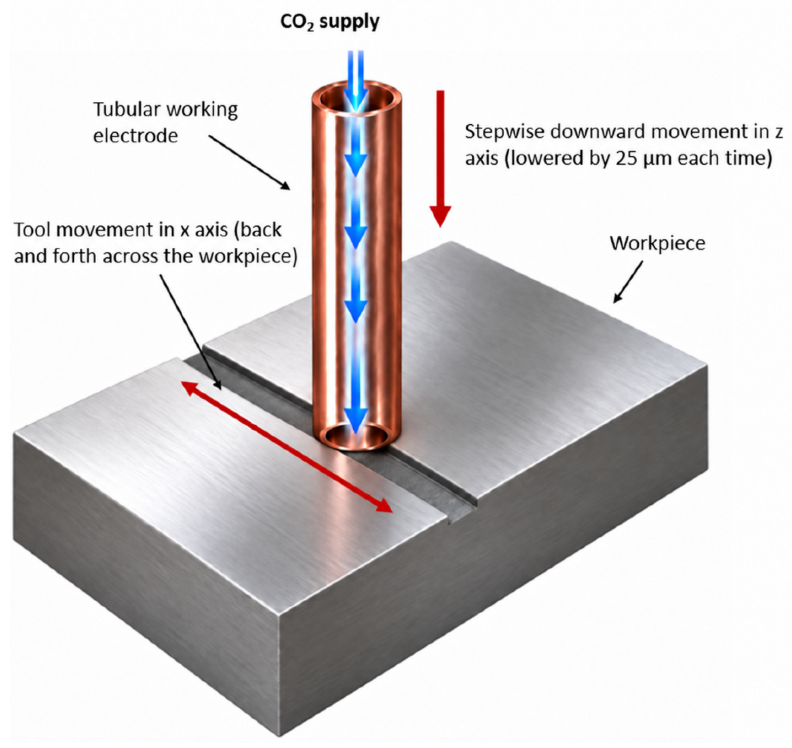
During each test, ten layers of material were removed, alternating in two directions, with the working electrode lowered by 25 µm each time a layer of material was milled (Figure 3). This approach made it possible to compensate for the differences in the shape of the groove obtained during the wear of the copper tubular working electrode. The removal of ten layers made it possible to stabilise the conditions in the machining zone while obtaining reliable results. The number of ten layers was considered optimal during the preliminary tests carried out.
Figure 3.
Milling kinematics scheme.
During the preparation of this manuscript, ChatGPT (OpenAI; primarily GPT-6) was used to improve the visual presentation of schematic figures (Figure 1, Figure 2a and Figure 3). The original sketches were created by the authors, with AI used solely to improve their graphical presentation. The authors have reviewed and edited the output and take full responsibility for the content of this publication.
2.2. Experimental Plan
Tests were performed in accordance with the central composition research plan, within the following ranges of variation in the input parameters:
- Pulse-on time ti: 100 µs–500 µs;
- Open-circuit voltage U: 80 V–120 V;
- Current intensity I: 0.9 A–4.5 A;
- Gas pressure p: 2 bar–10 bar.
On this basis, a modified central composite design was used comprising 25 machining runs for each material: 16 factorial points, six axial points, and three independent centre-point runs. The centre conditions were ti = 300 µs, U0 = 100 V, I = 2.7 A, and p = 6 bar. Three independent runs were performed at the design centre to estimate pure experimental error. Each run constituted a separate machining experiment. The three replications provided two degrees of freedom for pure-error estimation. Axial points were included for pulse-on time, current, and CO2 inlet pressure. The limits of variation in the input parameters are related to the limitations of the equipment—the limited range of adjustment of the EDM controller and pulse generator on the test bench as well as the limitations of the carbon dioxide reducer. Voltage axial points were omitted because of generator operating limits. The investigated ranges were 100–500 µs, 80–120 V, 0.9–4.5 A, and 2–10 bar, respectively. These values correspond to the available controller settings. The tubular copper tool electrode was not replaced after each machining run; however, its axial shortening was determined separately for every run using contact measurements. Runs were performed in randomised order. The run identifiers in Table 2 therefore describe the design matrix rather than chronological execution order. The three independent centre-point runs provided two pure-error degrees of freedom per material. This estimate describes the variability at the design centre and does not establish uniform variability throughout the experimental domain.
Table 2.
Input parameters during near-dry EDM.
The input parameters for performed tests are given in Table 2. For the central input parameters, three repetitions of the trials were carried out. The constant machining conditions are presented in Table 3.
Table 3.
Constant machining parameters during tests.
2.3. Output Parameters’ Measurements
The primary objective of this study was to determine the impact of electro-discharge machining conditions on the technological quality and efficiency of the process during the near-dry EDM process. To achieve the objectives, this study describes the surface roughness parameters measured with a Taylor Hobson scanning profilometer (Taylor Hobson, AMETEK, Inc., Leicester, UK) with Ultra Version software (version 6.6.124). Roughness profiles were measured along the machined grooves, parallel to their longitudinal direction, using a Gaussian filter and an evaluation length of 12.5 mm. For each analysed surface, three roughness measurements were taken at different locations, and their arithmetic mean was calculated. For selected parameters, the following were used: SEM photographs and EDS analysis using a JSM5510LV scanning microscope. Additionally, the material-removal rate and working electrode wear were calculated also for all the trials.
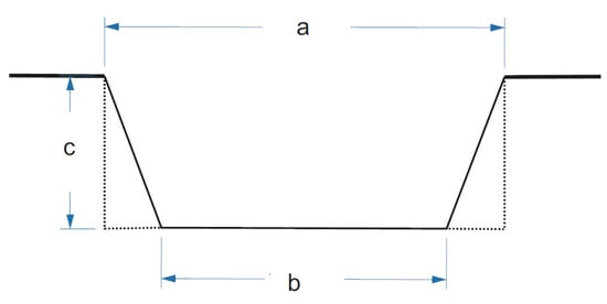
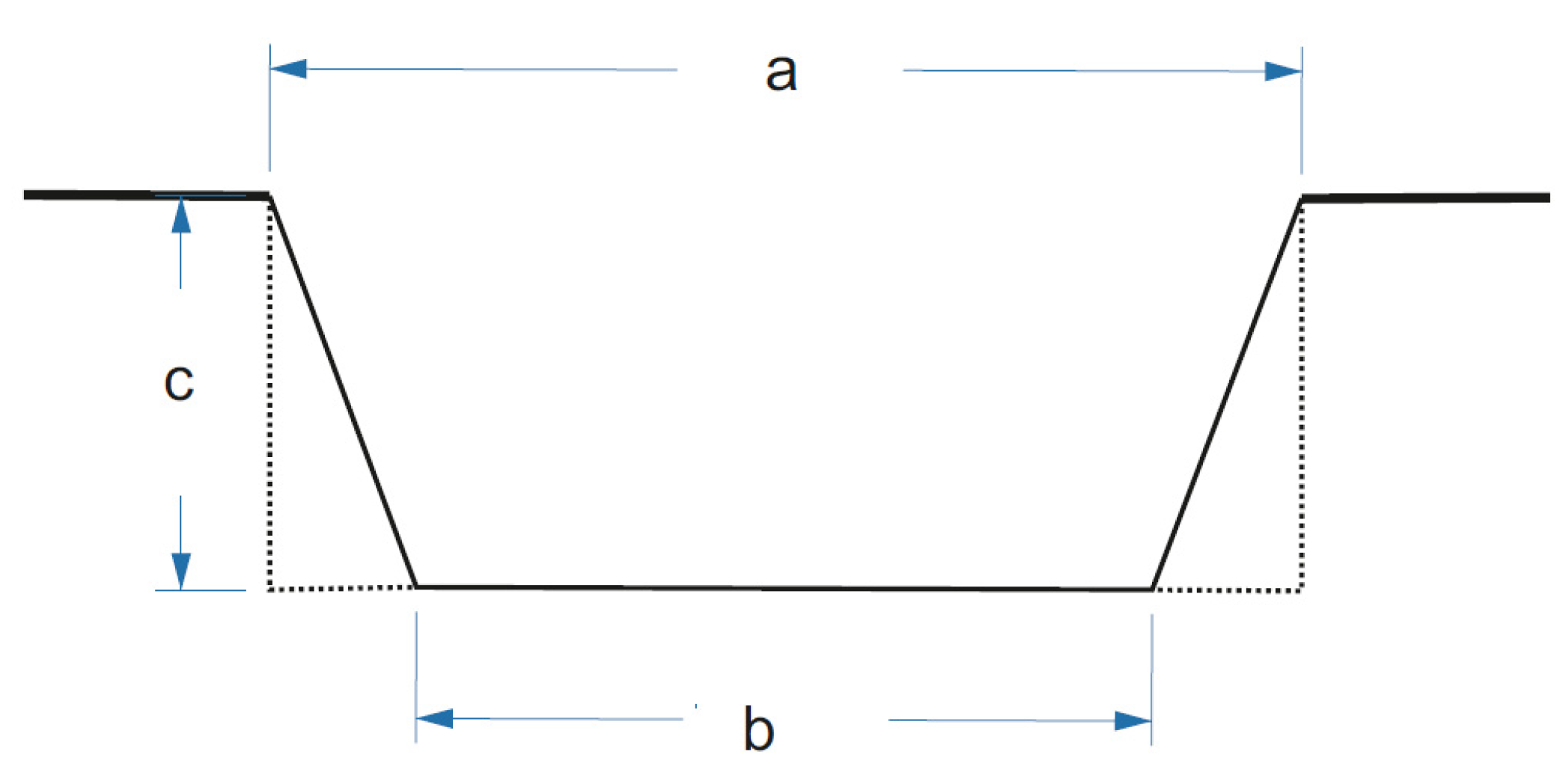
Lateral wear of the tool electrode produced an approximately trapezoidal groove cross-section, as illustrated in Figure 4. To account for bidirectional machining, the groove height (c) and width (b) were measured in triplicate at the electrode entry and exit positions, respectively. Groove width (a) was also measured three times. The arithmetic mean of each dimension was used in the subsequent calculations. The groove length is described as (l). Groove dimensions were measured using an Olympus BX53M, equipped with it camera Olympus SC50 with Olympus Stream Essentials 2.3.3 (build 17023).
Figure 4.
Cross-section of a single groove with measured values.
The removed workpiece volume was calculated as
The material-removal rate value is calculated according to the formula
where t is the total machining time per trial.
The relative percentage wear of the working electrode is calculated as follows:
where Ve is the volume of working electrode material removed per trial.
Tool-electrode shortening was monitored by recording the initial and final positions of the electrode tip relative to a zero reference established on the specimen surface. The Z coordinates were obtained from the machine controller and used to determine the axial shortening of the electrode for each machining trial. The adopted method for estimating electrode wear did not allow copper erosion to be distinguished from material deposition on the tool tip. Adherent deposits may partially mask shortening, as deposition-related low tool wear has been reported in dry EDM [33]. Visual inspection provides only qualitative indications of possible deposition. Consequently, zero-measured shortening cannot establish either the absence of electrode erosion or its compensation by deposited material, and the reported EW values should be interpreted as apparent wear derived from dimensional measurements.
The volume of electrode material lost was estimated from the measured shortening and the tubular electrode geometry. The internal channel diameter was measured using an optical microscope. The removed volume was calculated as the difference between the volumes of two coaxial cylinders whose height equalled the measured electrode shortening.
The study also investigates microstructural changes in the area affected by the heat generated during discharge, for selected input parameters. Metallographic sections were prepared in the cross-sectional direction to visualise the areas of the material directly influenced by the working electrode. The sections preparation process involved grinding the surface with abrasive papers ranging from 180 to 2000 grit, followed by polishing with diamond polishing paste using ethyl glycol with a gradation of 6 µm and 1 µm. The surface of the Inconel 625 alloy was polished using a suspension of diamond polishing paste with ethyl glycol with a gradation of 6 µm and 1 µm. Subsequently, an electrolytic etching process was carried out at 12 V and 3 s in a solution of 10 g CrO3 and 100 mL distilled water to reveal the microstructural structure. The etching process for Titanium Grade 2 was carried out in Kroll’s reagent: 10ml HNO3 + 20 mL HF + 20 mL glycerine. The described procedure enabled an analysis of changes in the surface layer perpendicular to the sample surface (along its cross-section).
3. Discussion of the Results
3.1. Near-Dry EDM Milling
The experimental results underwent statistical analysis, including correlation analysis to investigate potential correlations between input and output factors. Table 4 and Table 5 summarise the Pearson correlation coefficients (r) between the analysed input and output variables for both investigated materials. Correlation coefficients marked in red in the tables are significant with p < 0.05. The analysis does not consider interactions between input variables, which will be considered when assigning responses. Table 4 presents correlations for Inconel 625, Table 5 for Titanium Grade 2.
Table 4.
Correlation coefficient values between the analysed dependent and independent variables, Inconel 625.
Table 5.
Correlation coefficient values between the analysed dependent and independent variables, Titanium Grade 2.
In the next step, the ANOVA analysis was carried out. The analysis was performed for the central composition model, for which the experimental tests were conducted. The statistically significant parameters based on this analysis for the Inconel 625 for the variable Vv (material-removal rate) are current intensity, pulse time and gas pressure, for EW (working electrode wear) are current intensity and voltage, and for roughness parameters Rz and Ra it is current intensity. In case of Titanium Grade 2, statistically significant parameters for the machining performance variable Vv are voltage and current, pulse time and gas pressure, for the EW is current, and for the roughness parameters Rz and Ra is current.
The positive response variables were represented using an exponential second-order model with two-factor interactions. The model was expressed as follows:
where
In this expression, b0 is the intercept, bi are the linear coefficients, bij are the two-factor interaction coefficients, and bii are the quadratic coefficients. The coefficients were estimated using the MATLAB (Matlab 2020) regstats function by applying ordinary least-squares regression to the natural logarithm of each positive response. Predictions in the original response scale were obtained by exponentiating the fitted logarithmic responses. The Vv, Rz, and Ra responses for both materials, as well as relative tool-electrode wear EW for Inconel 625, were described using the model defined above. No model was fitted to the tool-electrode response for Titanium Grade 2 because two runs showed net electrode mass gain. With 25 observations and 15 estimated coefficients, each model had 10 residual degrees of freedom. Pure experimental error was estimated from three independent runs performed at the design centre (ti = 300 µs, U = 100 V, I = 2.7 A and p = 6 bar), providing two pure-error degrees of freedom. Model performance was evaluated using R2, adjusted R2, RMSE, the overall model F-test, lack-of-fit testing, and residual diagnostics. All statistics were calculated in the logarithmic response scale, and statistical significance was assessed at α = 0.05.
Because the pure-error estimate was based on only three centre-point runs, the lack-of-fit test had limited statistical power. Therefore, a non-significant lack-of-fit result was not considered sufficient evidence of model adequacy. The overall model test, goodness-of-fit measures, residual diagnostics, and physical plausibility of the fitted relationships were considered jointly when interpreting model performance. A summary of the statistical performance, diagnostic results, and recommended interpretation of the fitted models is provided in Table 6. Measured and model-predicted values of the investigated responses are reported in the Supplementary Material.
Table 6.
Statistical performance of the regression models.
The statistical performance of the fitted response-surface models varied depending on the analysed response and workpiece material. The models describing the volumetric material-removal rate Vv showed the strongest performance for both materials. The models were statistically significant and exhibited high adjusted coefficients of determination in the logarithmic response scale. However, statistically significant lack of fit was identified for both materials. In addition, the Inconel 625 model showed evidence of heteroscedasticity. Consequently, the Vv models were considered to reproduce the dominant response trends but were not interpreted as fully validated high-precision predictive models.
The Rz and Ra models for Titanium Grade 2 were also statistically significant and showed no significant lack of fit. These models were therefore retained as empirical approximations of the principal roughness trends within the investigated parameter region. In contrast, the complete Rz and Ra models for Inconel 625 were not statistically significant and exhibited relatively low adjusted R2 values. The pronounced differences between R2 and adjusted R2 indicate that the improvement in fit provided by the complete second-order models was limited relative to their complexity. The corresponding response surfaces were therefore used only as descriptive visualisations of the measured tendencies and not for quantitative prediction or optimisation. The model describing relative tool-electrode wear EW during the machining of Inconel 625 was also not statistically significant and showed limited explanatory performance. It was therefore used only for descriptive trend analysis and not for determining optimum process conditions.
The differences in model performance can be related to the stochastic nature of the EDM process and to the physical scale represented by each response. The adopted second-order functions describe the average response of the process but do not explicitly represent random variations associated with individual discharge events. Each discharge may occur at a different location, transfer a different amount of energy, generate a crater of different geometry, and remove a different quantity of material. Those effects become particularly important for responses governed by local surface morphology, whereas cumulative responses such as the volumetric material-removal-rate are less sensitive to individual stochastic events and therefore exhibit more regular statistical behaviour. Random variations in the location and intensities of individual discharges are therefore partially averaged over the machining time, producing a comparatively regular relationship between Vv and the controlled process parameters. Nevertheless, the significant lack of fit observed for both Vv models indicates that the second-order functions did not capture all systematic variation in the experimental data. Possible sources of this variation include changes in discharge stability, the proportion of ineffective pulses, debris accumulation, and variations in the effectiveness of molten-material removal by the CO2 flow. Surface roughness parameters are sensitive to the local spatial distribution, dimensions, and overlap of individual discharge craters. They are also affected by occasional unstable discharges, local debris accumulation, molten-material redeposition, and the position of the measured profile. Accordingly, independent surfaces machined under nominally identical conditions may exhibit similar volumetric removal rates but different local topographies. This effect was particularly evident for Inconel 625, for which substantial variability occurred among the centre-point roughness measurements. The verified high Rz value is interpreted as genuine process variability rather than a measurement error. The influence of the controlled parameters was therefore partly obscured by local stochastic effects, and the complete roughness models did not reach statistical significance. For Titanium Grade 2, the Rz and Ra models captured a statistically significant part of the experimental variability. These models are consequently interpreted as empirical descriptions of the dominant roughness trends rather than high-precision predictive relationships. The tool-electrode response is additionally governed by competing copper-removal and material deposition processes. This competition reduces the direct correspondence between the electrical and flow parameters and the measured net mass change. For Titanium Grade 2, the occurrence of unquantified net electrode mass gain whose magnitude was not quantified made the response unsuitable for quantitative exponential modelling.
The following section presents three-dimensional response surfaces illustrating the relationships between selected process parameters and the analysed responses. The surfaces were generated by exponentiating the predictions of the second-order models fitted to the logarithmically transformed responses. For each surface, two process parameters were varied over their investigated ranges, whereas the remaining parameters were held constant at the values specified in the corresponding figure caption, typically at the design-centre levels. For statistically significant models, the response surfaces were used to illustrate the dominant empirical trends within the investigated design region. Surfaces corresponding to non-significant complete models were interpreted only as descriptive visualisations of the measured tendencies. The response surfaces presented below were also used to identify the highest model-predicted responses within the investigated design region. These parameter combinations were obtained from the fitted empirical models and were not tested in separate confirmation experiments. Consequently, the maxima discussed below represent model-based point predictions rather than experimentally validated operating conditions. Only the parameter combinations listed in the experimental-design matrix were tested directly. No extrapolation beyond the investigated factor ranges was performed. However, predicted values at untested combinations within these ranges should be interpreted cautiously because prediction intervals were not available and lack of fit was identified for selected models.
3.2. Material-Removal Rate
The complete Vv models were statistically significant for both material–polarity configurations. The fitted response surfaces indicated trends associated with discharge current, pulse duration, and gas pressure for Inconel 625, and additionally with voltage for Titanium Grade 2. Because the effects of individual factors were not evaluated using term-level statistical tests, these relationships are interpreted as model-predicted trends rather than statistically confirmed individual effects.
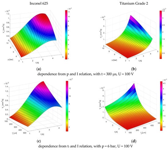
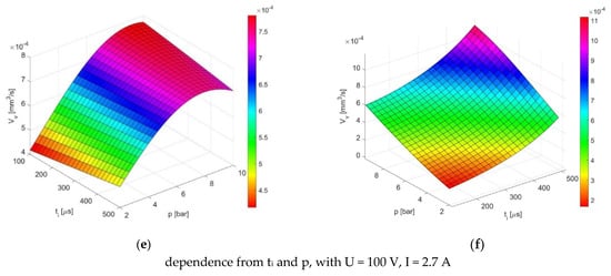
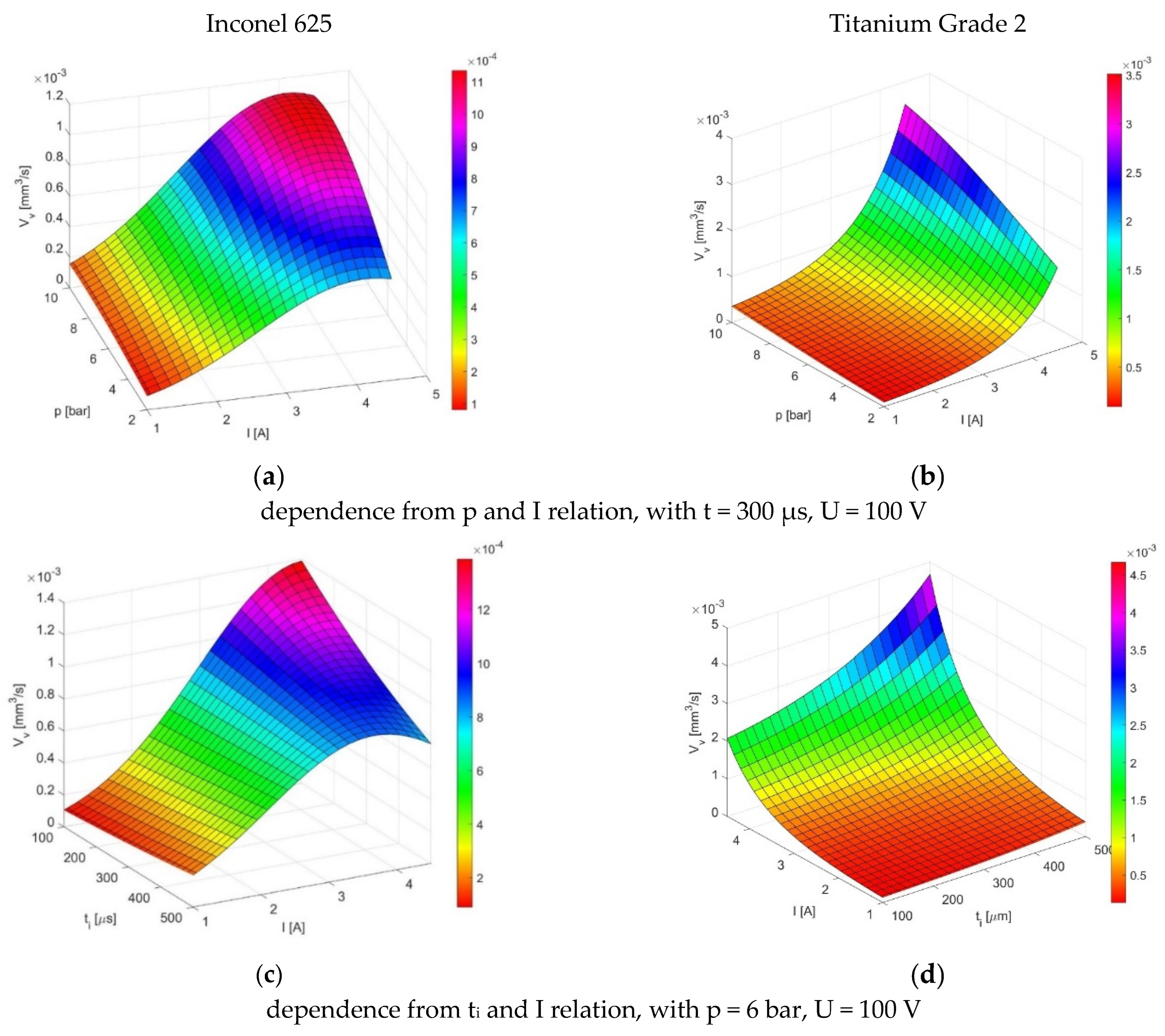
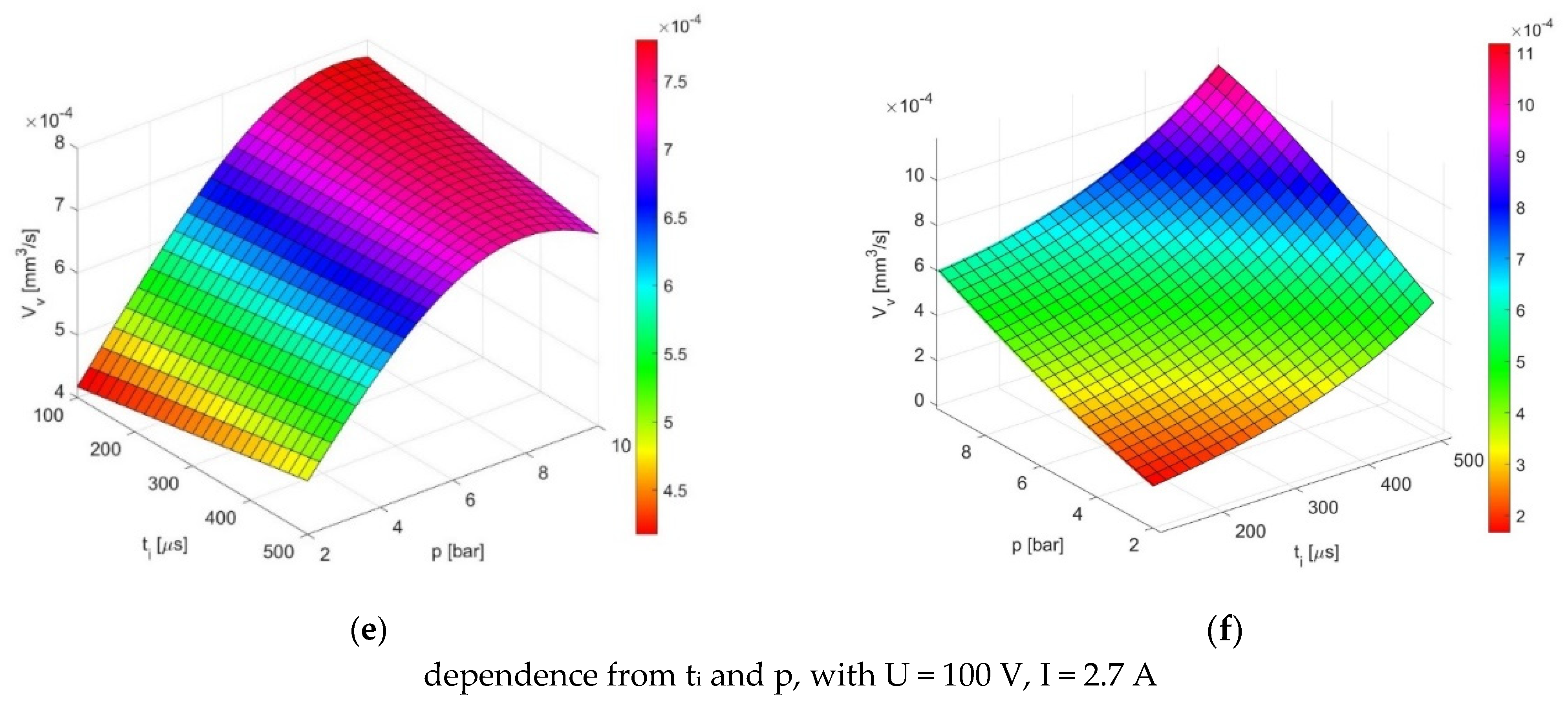
Figure 5 presents response surfaces generated from the fitted regression models, with the two non-varied parameters held at the values specified in each panel. Experimental measurements were obtained only for the parameter combinations listed in Table 2; values at other combinations are model estimates.
Figure 5.
Comparison of dependences of material-removal rate Vv from input parameters for Inconel 625 and Titanium Grade 2 (model predictions).
Among the tested conditions, the highest measured Vᵥ for Inconel 625 Figure 5a was 1.691 × 10⁻³ mm3/s at ti = 200 μs, U = 120 V, I = 3.6 A, and p = 8 bar. For Titanium Grade 2 Figure 5b, the highest measured value was 2.085 × 10⁻³ mm3/s at ti = 300 μs, U = 100 V, I = 4.5 A, and p = 6 bar. These values represent the largest responses recorded in the experimental dataset.
For Inconel 625, the fitted surface in Figure 5c indicates increasing Vᵥ with increasing current and decreasing pulse duration. At ti = 100 μs and I = 4.5 A, the model estimate is approximately 1.4 × 10⁻³ mm3/s under the fixed conditions of that panel. For Titanium Grade 2 (Figure 5d), the fitted surface remains relatively low at currents below approximately 3 A across the plotted pulse-duration range. At higher currents, the surface rises more steeply, and longer pulses correspond to higher predicted removal rates. At I = 4.5 A, the plotted estimates reach approximately 4.5 × 10⁻³ mm3/s as pulse duration increases.
The fitted surface for Inconel 625 in Figure 5e generally increases with CO2 pressure. Above approximately 6 bar, it shows less variation with pulse duration, whereas between 2 and 6 bar, shorter pulses correspond to higher predicted Vᵥ. For Titanium Grade 2, Figure 5f, the model indicates increasing Vᵥ with both pressure and pulse duration, with an estimate of approximately 1.1 × 10⁻³ mm3/s at ti = 500 μs and p = 10 bar.
The estimates at simultaneous axial extremes require particular caution. Combinations such as I = 4.5 A with p = 10 bar, ti = 100 μs with I = 4.5 A, and ti = 500 μs with either I = 4.5 A or p = 10 bar were not tested and lie outside the convex hull of the experimental-design points. Surface values in these regions are extrapolations requiring experimental confirmation. Neither these predictions nor the highest measured responses establish global process optima. Furthermore, comparisons between the materials concern the respective Cu(+)/Inconel 625(−) and Cu(−)/Titanium Grade 2(+) configurations, so material and polarity effects cannot be separated.
3.3. Surface Roughness Parameters
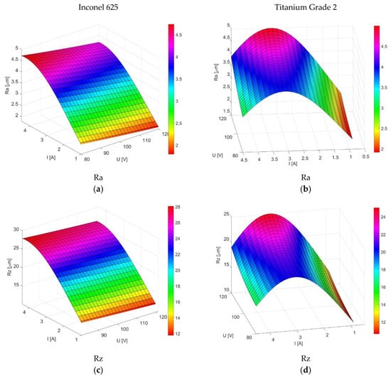
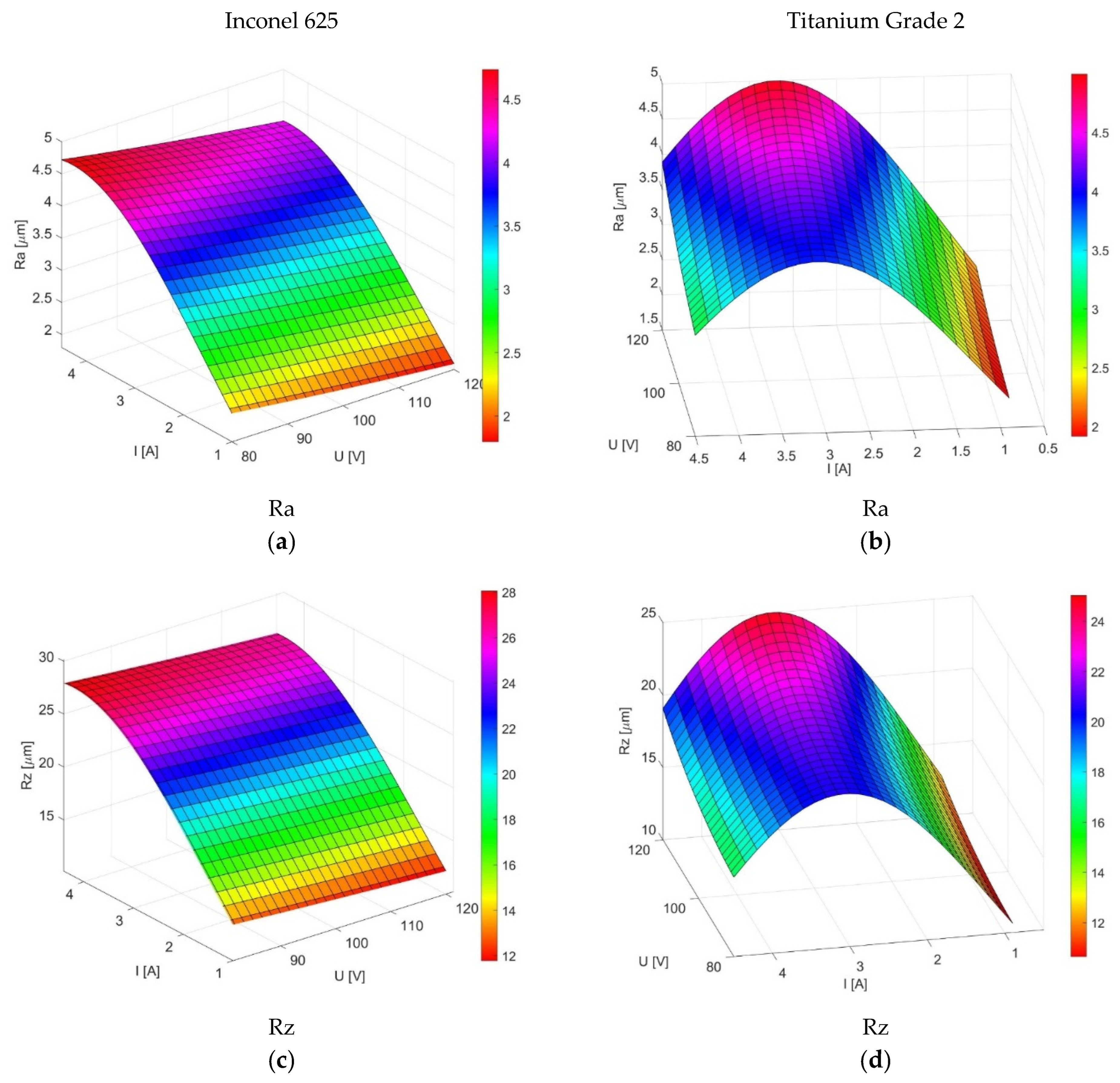
The following plots show the relationships between the selected surface roughness parameters, Ra and Rz, and the input variables identified by ANOVA as having the strongest effect on these responses. Considering the previously determined correlations between the roughness parameters, particularly the strong linear correlation between Ra and Rz, the similarity between the trends observed in Figure 6a,b is expected. In case of Inconel 625, both Ra and Rz (Figure 6c,d) increase with increasing current intensity over the investigated range of 0.9–4.5 A, with current intensity showing the strongest influence on both parameters. In all cases, the highest roughness values, Rz = 27 µm and Ra = 4.7 µm, were obtained at the maximum current intensity of I = 4.5 A. For Titanium Grade 2, both roughness parameters increase with increasing current intensity and voltage, reaching maximum values of approximately Ra = 5 µm and Rz = 25 µm at a current intensity of about 3 A. At higher current levels, both Ra and Rz decrease.
Figure 6.
Comparison of dependences of surface roughness from input parameters for Inconel 625 and Titanium Grade 2.
3.4. Working Electrode Wear
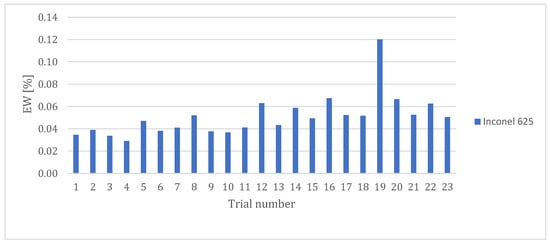
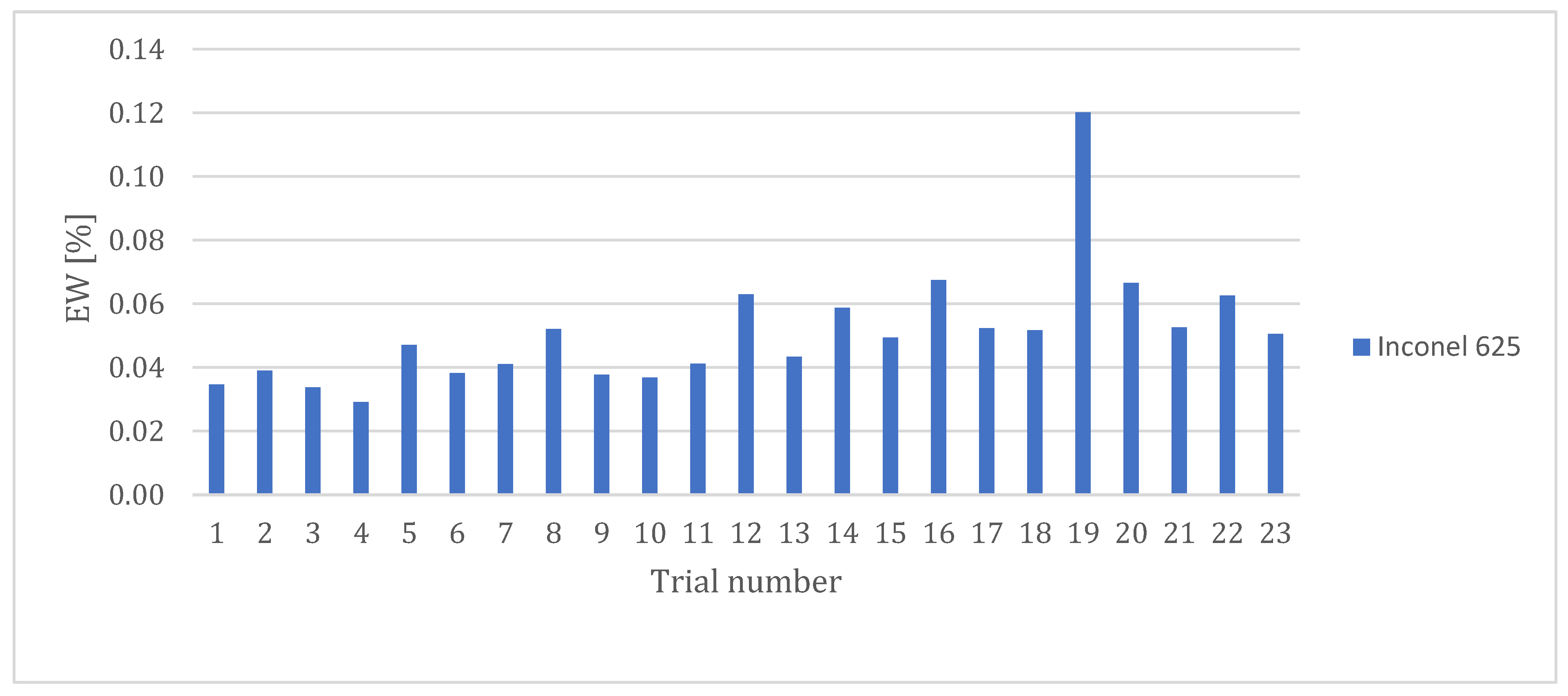
The relative percentage wear of the tool electrode presented in Figure 7 was considerably higher for Inconel 625 in all the cases analysed. This suggests that expressing electrode wear solely in relative terms may not provide a reliable measure for comparing the two materials. In the case of Titanium Grade 2, erosion products were deposited on the tool electrode surface, which in most cases resulted in negligible relative tool-electrode wear. Consequently, the calculated relative wear may underestimate the actual changes occurring at the tool electrode during machining. For that reason, the relative wear of working electrode of Titanium Grade 2 was not reported on the graph.
Figure 7.
Working electrode wear. The centre-point condition for Inconel 625 was tested three times, and its plotted response represents the arithmetic mean of these three repetitions (trail number 23).
3.5. SEM
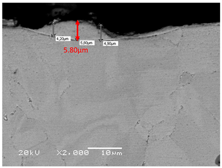
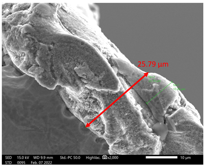
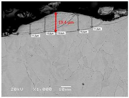
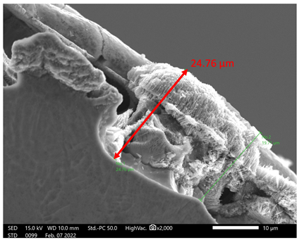
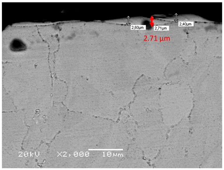
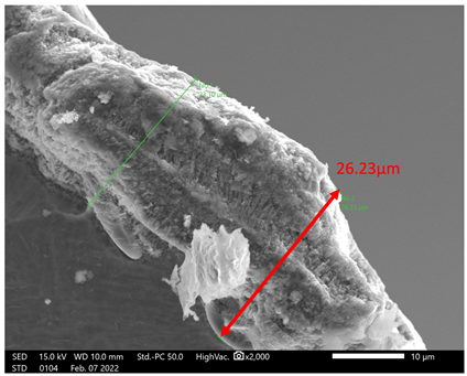
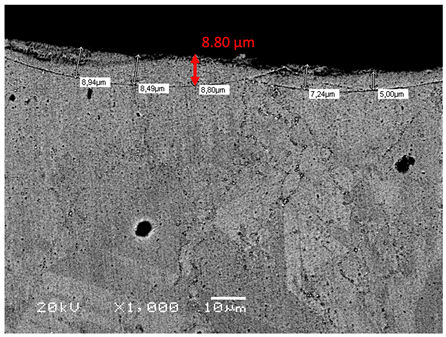
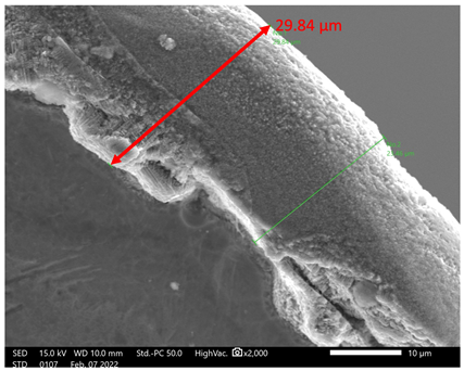
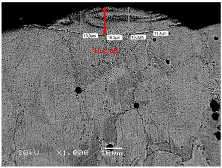
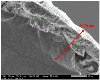
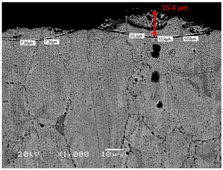
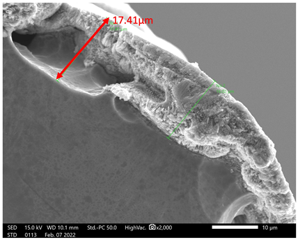
In Table 7, the comparison of the maximum recast-layer thicknesses of Inconel 625 and Titanium Grade 2 machined with the same parameters are presented. Microstructural changes induced by EDM were examined on transverse metallographic sections through the machined regions, exposing the material beneath the surface directly affected by the tool electrode. The specimens were ground sequentially using abrasive papers ranging from 180 to 2000 grit, followed by polishing with 6 μm and 1 μm diamond abrasives in an ethylene glycol-based medium. To reveal the microstructure, the polished Inconel 625 specimens were electrolytically etched at 12 V for 3 s in a solution prepared from 10 g of CrO3 and 100 mL of distilled water. Titanium Grade 2 specimens were chemically etched using a mixture of 10 mL HNO3, 20 mL HF, and 20 mL glycerol. The same specimen-mounting arrangement and SEM observation geometry were used for both materials. Differences in image presentation were intended solely to improve visualisation of the recast-layer morphology and highlight differences between the materials. Thickness measurements were performed directly using the software integrated with the SEM. Images were acquired in the central region of each specimen cross-section, and the reported values represent the greatest local thicknesses observed within the examined fields. These measurements were not averaged. The SEM micrograph was acquired in high-vacuum mode at an accelerating voltage of 15.0 kV and a working distance of 9.9 mm, using secondary-electron detection at a magnification of ×2000 and ×1000.
Table 7.
The comparison of the maximum recast-layer thicknesses of Inconel 625 and Titanium Grade 2.
Comparing both materials, the differences can be clearly seen. In each case, maximum recast-layer thickness is thicker for Titanium Grade2. The maximum thickest layer was observed in the trial where the highest current intensity (ti = 300 µs, U = 100 V, I = 4.5 A, p = 6 bar) was applied. Also, very high thickness of recast layer was identified for machining with the lowest pressure (ti = 300 µs, U = 100 V, I = 2.7 A, p = 2 bar). In the case of Inconel 625, the maximum recast-layer thickness might be observed with the longest pulse time (ti = 500 µs, U = 100 V, I = 2.7 A, p = 6 bar) and also with the lowest pressure (ti = 300 µs, U = 100 V, I = 2.7 A, p = 2 bar. For both materials, the local maximum recast-layer thicknesses observed at 2 bar may reflect the combined effects of heat transfer, flushing, and discharge behaviour. These measurements alone do not establish that this pressure provided insufficient workpiece cooling. The thicker modified surface layer observed on Titanium Grade 2 cannot be attributed only to differences in thermal conductivity. In fact, Inconel 625 has a lower thermal conductivity and therefore a greater tendency to retain heat close to the discharge zone. The thicker recast layer observed on Titanium Grade 2 indicates that a larger fraction of the material melted during discharge remained on the surface and resolidified after the pulse. Furthermore, this behaviour of titanium appeared to also be governed to a large extent by its high chemical affinity for oxygen. At elevated temperatures, titanium readily forms oxides and also allows oxygen to diffuse into the near-surface region. Under near-dry EDM conditions, repeated cycles of rapid heating, melting and resolidification take place in a CO2-containing environment, which may favour oxygen incorporation into the resolidified layer. The oxidation behaviour of Inconel 625 is different. Its surface response is largely controlled by selective oxidation of chromium and the formation of Cr-rich oxides, which can restrict further oxygen transport. As a result, oxide growth and oxygen penetration do not proceed in the same way as in titanium. The observed differences may reflect the combined influence of material properties and polarity. Thermophysical-property arguments provide a basis for discussing these results but do not isolate an independent material effect. Likewise, the measured carbon and oxygen enrichment does not establish the formation of specific carbide or oxide phases.
Titanium Grade 2 was machined with the workpiece connected to the positive pole, whereas Inconel 625 was machined with the workpiece connected to the negative pole. Thus, even for the same nominal values of current, voltage, pulse duration and gas pressure, the actual thermal load imposed on the workpiece surface may differ. The thicker layer formed on Titanium Grade 2 is therefore most likely related to the combined effect of polarity-dependent energy transfer, lower material-removal efficiency, repeated resolidification and the strong tendency of titanium to react with oxygen.
3.6. EDS
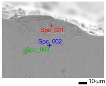
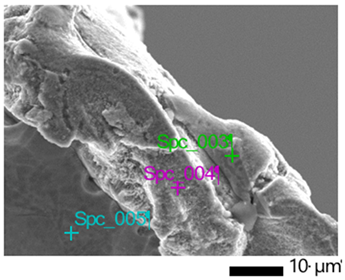
EDS analysis was used to assess changes in the chemical composition of the surface layer formed during EDM milling. EDS analyses were performed on uncoated cross-sections of Inconel 625 and Titanium Grade 2. Measurements were carried out on metallographic cross-sections using point analysis, with the chemical composition determined separately for the recast layer and the unaffected base material. The same specimen-mounting arrangement and SEM observation geometry were used for both materials. No carbon or metallic coating was applied. Measurements were acquired in the central region of each specimen cross-section, selected to represent stable machining conditions. Analysis points were located within the recast layer and the nominally unaffected substrate. Measurements were performed after metallographic etching. Elemental concentrations were expressed as mass fractions (wt.%), and the results were used primarily for qualitative comparisons of elemental composition. The statistical definition and confidence level of the originally tabulated ± values could not be verified from the available records. These values are therefore not interpreted as established measurement uncertainties or as indicators of overall analytical accuracy.
The carbon and oxygen results are interpreted primarily qualitatively. Although the EDS software provides numerical composition estimates, these values are not treated as validated measurements of bulk composition or elemental uptake during machining.
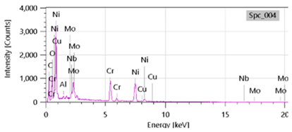
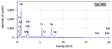
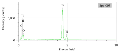
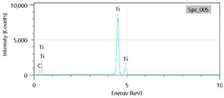
The X-ray spectra obtained for both Titanium Grade 2 and Inconel 625 showed an increased concentration of oxygen and carbon in the recast layers (Table 8 and Table 9). The apparent carbon contents in the nominally unaffected substrate, approximately 1.00% for Titanium Grade 2 and 3.46% for Inconel 625, exceed the certified bulk compositions. Possible contributions from specimen preparation, residual polishing or etching media, and hydrocarbon contamination therefore cannot be excluded. The absence of an applied coating eliminates that particular source of carbon but does not exclude other preparation or contamination effects. Oxygen signals may likewise include contributions from surface oxidation and specimen preparation, in addition to machining-related changes.
Table 8.
EDS analysis of Inconel 625 and Titanium Grade 2, selected case.
Table 9.
Representative elemental spectra at two selected points Inconel 625 and Titanium Grade2, ti = 300 µs, U = 100 V, I = 2.7 A, p = 2 bar.
Consequently, differences in the reported carbon and oxygen values between the recast layer and substrate are regarded as apparent local variations requiring cautious interpretation. They do not independently establish diffusion, incorporation of species originating from CO2, or the formation of specific carbide or oxide phases. Such interpretations remain hypotheses requiring complementary analysis. The composition measured at point Spc_002 also suggests that carbon diffusion into the subsurface region cannot be excluded. The presence of copper in the surface layer of Inconel 625 suggests partial melting of the tool electrode followed by transfer and resolidification of electrode material on the workpiece surface. The oxygen content in the surface layer of Titanium Grade 2 (Table 10) was significantly higher than that observed for Inconel 625 (Table 11). The chemical composition measured in the unaffected base material indicates that diffusion of carbon and oxygen into the substrate was limited. It should also be noted that quantitative determination of carbon by EDS is associated with considerable measurement uncertainty due to the low atomic mass of carbon. For this reason, the compositional results presented here should be interpreted qualitatively rather than quantitatively.
Table 10.
Mass fraction of individual elements at the analysed points, Titanium Grade 2, ti = 300 µs, U = 100 V, I = 2.7 A, p = 2 bar.
Table 11.
Mass fraction of individual elements at the analysed points, Inconel 625, ti = 300 µs, U = 100 V, I = 2.7 A, p = 2 bar.
3.7. Comparison of the Effects of Material Properties
The findings apply to the two investigated material–polarity combinations. Because polarity was selected separately for each material, the independent effects of material and polarity and their interaction cannot be determined from the present experimental design. For Inconel 625, the lower thermal conductivity and lower melting temperature favour heat accumulation close to the discharge site. As a result, the energy supplied during a pulse can more readily produce local melting and material removal. This is consistent with the lower Palatnik criterion obtained for Inconel 625. Under the conditions used in this study, stable machining was achieved with a positively polarised tool, whereas the opposite polarity caused a clear deterioration in machining performance and a substantial increase in tool wear.
Titanium Grade 2 showed a different response. Its higher thermal conductivity promotes faster heat dissipation from the discharge zone, while its higher melting temperature increases the energy required for local melting. Stable machining was obtained only when the tool electrode was negatively polarised. This agrees with observations reported for titanium and titanium alloys, where the effectiveness of material removal has been shown to depend strongly on polarity. In these materials, the polarity effect has also been linked to changes in the surface layer, including the formation of TiC under certain EDM conditions.
The present results therefore suggest that the polarity effect should be considered together with the thermal and surface response of the workpiece material. The thermal properties determine how the material reacts to the discharge energy, while polarity affects where this energy is released and how the electrode–workpiece system evolves during successive discharges. This appears to be the main reason why the same electrical configuration was not equally effective for Titanium Grade 2 and Inconel 625.
Investigated materials differ not only in their chemical composition, as previously described, but also in their physical properties, which are presented in Table 12. The specific heat capacity, thermal conductivity and density correspond to 20 °C. The reference temperature for the adopted titanium and Inconel thermal conductivity was not specified.
Table 12.
Physical properties of the Inconel 625 alloy and Titanium Grade 2, Palatnik’s index [33,34,35].
The Palatnik criterion is employed to ascertain the EDM machinability level of a given material. It posits that thermal phenomena exert the most significant influence on material removal during EDM.
The Palatnik index is calculated from the following relationship [34]:
where
c [J/(kg · K)]—specific heat;
ρ [kg/m3]—density;
λ [W/(m · K)]—thermal conductivity coefficient;
θm [K]—melting point.
The higher the value of the Palatnik index, the lower the EDM machinability of the material, i.e., the more difficult the material is to machine by electrical discharge machining. When the thermal conductivity of the workpiece material is high, the heat generated by electrical discharges is dissipated more rapidly, which reduces the amount of material removed. Therefore, an increase in thermal conductivity is generally associated with a decrease in EDM machinability. According to the Palatnik criterion, EDM machinability decreases with the square of the melting temperature. This indicates that the melting temperature is one of the main factors governing the susceptibility of a material to electro-erosive removal. However, the Palatnik criterion does not account for other thermophysical properties, such as the latent heat of fusion or the latent heat of vaporisation, which may also affect EDM machinability. Latent heat represents the amount of energy absorbed or released by a material during a phase change. A material characterised by a high latent heat therefore requires a greater amount of energy to melt or vaporise, which may result in lower EDM machinability [3].
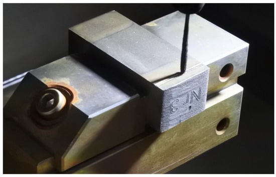
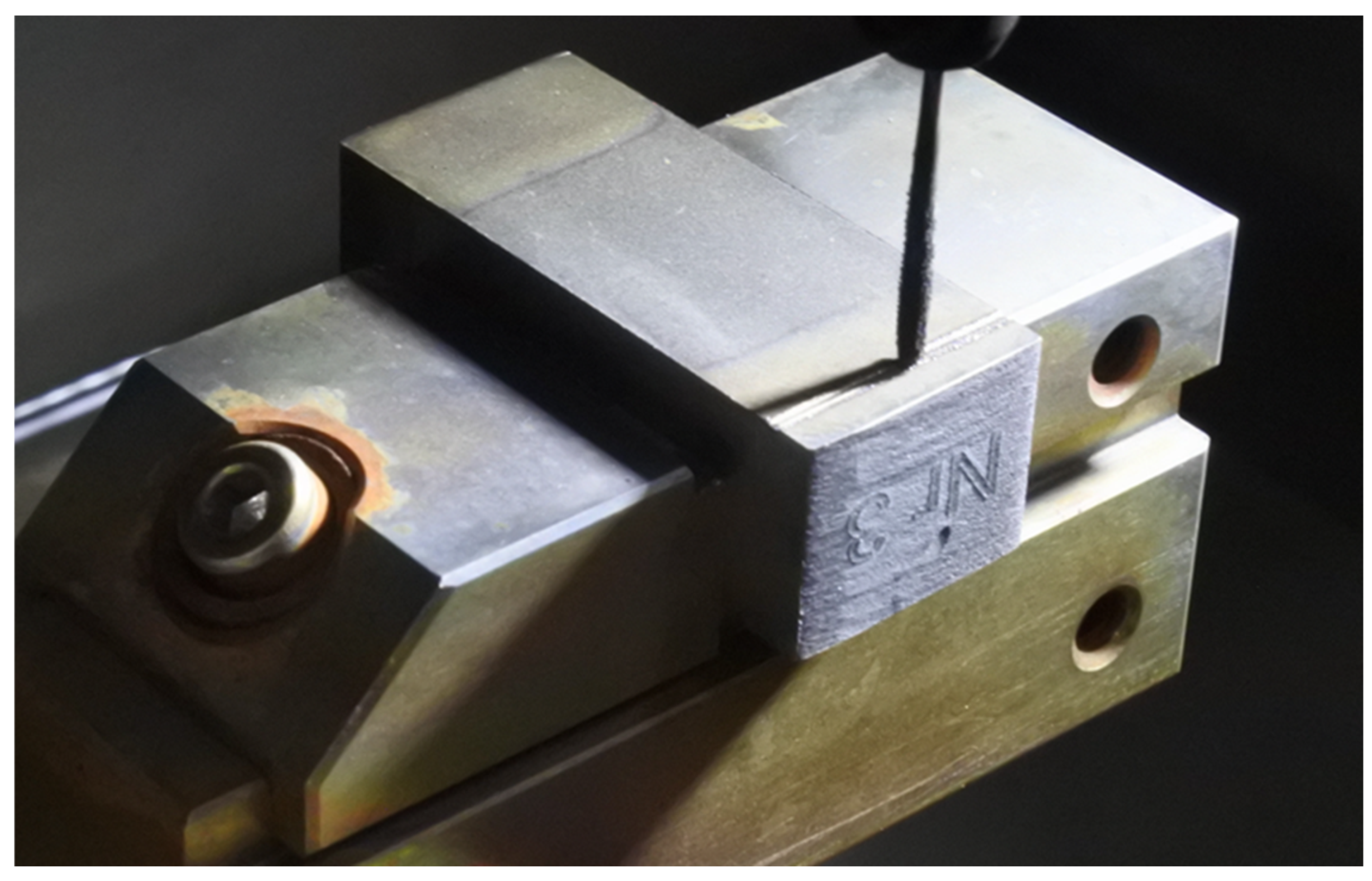
The calculations presented in Table 12 show that the Palatnik index for Titanium Grade 2 is approximately 2.04 times higher than that for Inconel 625. Titanium Grade 2 should therefore be expected to exhibit lower EDM machinability. However, it is important to mention that during machining, the deposition of workpiece material on the surface of the tool electrode was observed (Figure 8). This phenomenon has also been reported in the literature and is one of the reasons why relative tool-electrode wear in gaseous EDM is generally lower than that observed when liquid dielectrics are used.
Figure 8.
Titanium Grade 2 deposition on the working electrode.
The Palatnik criterion provides a simplified thermophysical indicator of resistance to thermal erosion rather than a quantitative predictor of material removal in CO2-assisted EDM. It does not explicitly account for electrode polarity, generator-dependent discharge characteristics, gas-assisted evacuation of molten material and debris, material transfer between the electrodes, or thermochemical interactions with the working medium. These limitations are particularly relevant because Inconel 625 was machined using the Cu(+)/workpiece(−) configuration, whereas Titanium Grade 2 was machined using Cu(−)/workpiece(+). The comparison therefore concerns two material–polarity combinations. The higher titanium removal rates obtained under some conditions, despite its higher Palatnik index, cannot consequently be interpreted solely in terms of workpiece thermophysical properties.
EDS analysis indicated higher carbon and oxygen concentrations in the recast layers of both materials than in their respective base materials. This enrichment is consistent with possible thermochemical modification of the surface layers. Such modification could affect the formation, solidification, and removal of molten material, but its contribution to the measured removal rates was not established. The EDS measurements alone do not identify the chemical states or crystalline phases associated with the detected elements. Thermochemical effects are therefore considered a possible contributor to the discrepancy between the Palatnik criterion and the experimental results, rather than a demonstrated mechanism.
The present study did not include a direct physical analysis of the phenomena occurring within the plasma channel during discharge. However, the literature indicates that plasma channel formation in gaseous EDM differs from that observed in liquid dielectrics, both in its development and in the accompanying physical phenomena. These differences may affect discharge behaviour, increase the sensitivity of the process to the interelectrode gap, and promote deposition of workpiece material on the tool electrode surface.
The results obtained from the Palatnik index calculations and the experimental tests confirm that the workpiece material and polarisation has a major influence on gaseous EDM milling, even when identical machining parameters are applied. The material type affected not only machining efficiency and material-removal rate but also tool-electrode wear and surface roughness. This confirms that material properties must be considered as an integral part of process design in gaseous EDM.
4. Conclusions
The investigated configuration uses deionised water and pressurised CO2 instead of a liquid hydrocarbon dielectric. Its environmental performance remains to be established through comparative measurements of water and gas consumption, energy use, and emissions under equivalent machining tasks and surface-quality requirements. The present results therefore support conclusions concerning machining performance and surface characteristics, without demonstrating reduced resource consumption or environmental impact.
The results indicate that dry and near-dry EDM cannot be designed using a single set of machining conditions for different workpiece materials. The response of the material to electrical discharges depends on its thermal and chemical properties and on its microstructure. These differences are reflected in material removal, electrode wear, discharge stability and the condition of the machined surface.
For both investigated materials, discharge current amplitude and gas pressure were among the most important factors affecting machining efficiency. The current determines the amount of energy supplied during discharge, while gas pressure influences the conditions in the interelectrode gap, particularly debris removal and discharge stability. Although the same factors were important for both materials, their effect on the process responses was not identical.
The present study demonstrates that the statistical performance of response-surface models in near-dry EDM is strongly influenced by the stochastic character of the material-removal mechanism. Responses based on cumulative process effects, such as volumetric material-removal rate, exhibited a more consistent relationship with the machining parameters. In contrast, responses governed by local surface morphology or by competing erosion and deposition phenomena showed greater experimental variability and lower predictive performance. Consequently, the Vv models were statistically significant and captured the dominant response trends for both workpiece materials, with R2 values for ln(Vv) of 0.968 for Titanium Grade 2 and 0.940 for Inconel 625. However, significant lack of fit indicated that these models should be interpreted as empirical trend models rather than high-precision predictive relationships. Surface roughness and tool-electrode response were more sensitive to local crater formation, debris accumulation, material redeposition, and other stochastic process phenomena. The roughness models for Titanium Grade 2 provided statistically significant empirical approximations, whereas the corresponding models for Inconel 625 were not statistically significant and were interpreted descriptively. The tool-electrode response was additionally affected by competing erosion and deposition processes, which limited its quantitative modelling.
Overall, the findings indicate that successful near-dry EDM requires a material-oriented approach in which electrical parameters, gas supply conditions and workpiece characteristics are considered together. This is particularly important when the process is developed as a more resource-efficient alternative to conventional EDM using liquid dielectrics.
Supplementary Materials
The following supporting information can be downloaded at https://www.mdpi.com/article/10.3390/ma19224881/s1. Table S1a. Experimental conditions and measured response values for Titanium Grade 2, Table S1b. Experimental conditions and measured response values for Inconel 625, Table S2. Overall model statistics and residual diagnostics in the logarithmic response scale, Table S3a. Regression coefficients of the log-transformed second-order models for Inconel 625, Table S3b. Regression coefficients of the retained log-transformed second-order models for Titanium Grade 2, Table S4a. Measured, predicted, and residual values for Vv, Titanium Grade 2, Table S4b. Measured, predicted, and residual values for Rz, Titanium Grade 2, Table S4c. Measured, predicted, and residual values for Ra, Titanium Grade 2, Table S5a. Measured, predicted, and residual values for Vv, Inconel 625, Table S5b. Measured, predicted, and residual values for Rz, Inconel 625, Table S5c. Measured, predicted, and residual values for Ra, Inconel 625, Table S5d. Measured, predicted, and residual values for w, Inconel 625, Table S6. Tool-electrode mass-balance results for Titanium Grade 2.
Author Contributions
Conceptualisation, A.Ż. and S.S.; methodology, A.Ż.; validation, A.Ż. and S.S.; formal analysis, A.Ż.; investigation, A.Ż.; resources, A.Ż. and W.B.; data curation, A.Ż. and W.B.; writing—original draft, A.Ż.; writing—review and editing, S.S.; visualisation, A.Ż.; supervision, S.S. All authors have read and agreed to the published version of the manuscript.
Funding
This research received no external funding.
Data Availability Statement
The original contributions presented in this study are included in the article/Supplementary Materials. Further inquiries can be directed to the corresponding author.
Acknowledgments
During the preparation of this manuscript, the authors used ChatGPT (OpenAI; primarily GPT-6) to improve the visual presentation of schematic figures (Figure 1, Figure 2a and Figure 3) they had originally created. The authors have reviewed and edited the output and take full responsibility for the content of this publication.
Conflicts of Interest
The authors declare no conflicts of interest.
References
- Rajurkar, K.P.; Sundaram, M.M.; Malshe, A.P. Review of Electrochemical and Electrodischarge Machining. Procedia CIRP 2013, 6, 13–26. [Google Scholar] [CrossRef] [Scilit]
- Żyra, A.; Bogucki, R.; Skoczypiec, S. Austenitic steel surface integrity after EDM in different dielectric liquids. Tech. Trans. 2017, 12, 231–242. [Google Scholar] [CrossRef] [Scilit]
- Żyra, A.; Bogucki, R.; Podolak-Lejtas, A.; Skoczypiec, S. Research on influence of heat treatment scheme of Ti10V2Fe3Al alloy on technological surface integrity after electrodischarge machining. J. Manuf. Process. 2021, 62, 47–57. [Google Scholar] [CrossRef] [Scilit]
- Hayakawa, S.; Kusafuka, Y.; Itoigawa, F.; Nakamura, T. Observation of Material Removal from Discharge Spot in Electrical Discharge Machining. Procedia CIRP 2016, 42, 12–17. [Google Scholar] [CrossRef] [Scilit]
- Chakraborty, S.; Dey, V.; Ghosh, S.K. A review on the use of dielectric fluids and their effects in electrical discharge machining characteristics. Precis. Eng. 2015, 40, 1–6. [Google Scholar] [CrossRef] [Scilit]
- Zhang, Y.; Liu, Y.; Shen, Y.; Ji, R.; Li, Z.; Zheng, C. Investigation on the influence of the dielectrics on the material removal characteristics of EDM. J. Mater. Process. Technol. 2014, 214, 1052–1061. [Google Scholar] [CrossRef] [Scilit]
- Kibria, G.; Sarkar, B.R.; Pradhan, B.B.; Bhattacharyya, B. Comparative study of different dielectrics for micro-EDM performance during microhole machining of Ti-6Al-4V alloy. Int. J. Adv. Manuf. Technol. 2009, 48, 557–570. [Google Scholar] [CrossRef] [Scilit]
- Kunleda, M.; Miyoshi, Y.; Takaya, T.; Nakajima, N.; ZhanBo, Y.; Yoshida, M. High Speed 3D Milling by Dry EDM. CIRP Ann. 2003, 52, 147–150. [Google Scholar] [CrossRef] [Scilit]
- Tao, J.; Shih, A.J.; Ni, J. Experimental Study of the Dry and Near-Dry Electrical Discharge Milling Processes. J. Manuf. Sci. Eng. 2008, 130, 011002. [Google Scholar] [CrossRef] [Scilit]
- Roth, R.; Kuster, F.; Wegener, K. Influence of oxidizing gas on the stability of dry electrical discharge machining process. Procedia CIRP 2013, 6, 338–343. [Google Scholar] [CrossRef] [Scilit]
- Baroi, B.K.; Jagadish; Patowari, P.K. A review on sustainability, health, and safety issues of electrical discharge machining. J. Braz. Soc. Mech. Sci. Eng. 2022, 44, 59. [Google Scholar] [CrossRef] [Scilit]
- Kao, C.C.; Tao, J.; Shih, A.J. Near dry electrical discharge machining. Int. J. Mach. Tools Manuf. 2007, 47, 2273–2281. [Google Scholar] [CrossRef] [Scilit]
- Singh, J.; Sharma, R.K. Green EDM Strategies to Minimize Environmental Impact and Improve Process Efficiency. J. Manuf. Sci. Prod. 2016, 16, 1–18. [Google Scholar] [CrossRef] [Scilit]
- Tao, J.; Shih, A.J.; Ni, J. Near-Dry EDM Milling of Mirror-Like Surface Finish. Int. J. Electr. Mach. 2008, 13, 29–33. [Google Scholar] [CrossRef] [Scilit]
- Bai, X.; Zhang, Q.; Zhang, J.; Kong, D.; Yang, T. Machining efficiency of powder mixed near dry electrical discharge machining based on different material combinations of tool electrode and workpiece electrode. J. Manuf. Process. 2013, 15, 474–482. [Google Scholar] [CrossRef] [Scilit]
- Communication from the Commission. The European Green Deal. Available online: https://eur-lex.europa.eu/legal-content/EN/TXT/?qid=1588580774040&uri=CELEX%3A52019DC0640 (accessed on 20 October 2026).
- Żyra, A.; Skoczypiec, S. Badania wstępne obróbki elektroerozyjnej w gazie z zastosowaniem dodatkowego chłodzenia przedmiotu obrabianego. Zarządzanie Przedsiębiorstwem 2019, 22, 25–32. [Google Scholar] [CrossRef]
- Żyra, A.; Bizoń, W.; Skoczypiec, S. Primary research on dry electrodischarge machining with additional workpiece cooling. AIP Conf. Proc. 2018, 2017, 020034. [Google Scholar] [CrossRef] [Scilit]
- Żyra, A.; Skoczypiec, S. Primary research on influence of workpiece cooling on efficiency of Inconel’s 625 alloy elecrodischarge milling in carbon dioxide. J. Phys. Conf. Ser. 2022, 2235, 012040. [Google Scholar] [CrossRef] [Scilit]
- Żyra, A.; Skoczypiec, S.; Bogucki, R. Selected aspects of surface integrity of inconel 625 alloy after dry-EDM in carbon dioxide. Key Eng. Mater. 2022, 926, 1681–1688. [Google Scholar] [CrossRef] [Scilit]
- Żyra, A. Influence of machining conditions on dry EDM with workpiece cooling of Inconel 625 alloy in the milling kinematics. Int. J. Adv. Manuf. Technol. 2024, 134, 2921–2937. [Google Scholar] [CrossRef] [Scilit]
- Talla, G.; Gangopadhyay, S.; Biswas, C.K. Influence of powder-mixed EDM on surface morphology and metallurgical alterations of Inconel 625. Aust. J. Mech. Eng. 2022, 21, 1533–1546. [Google Scholar] [CrossRef] [Scilit]
- Li, L.Q.; Zhao, W.S.; Wang, Z.L.; Kou, B.Q.; Li, L.Y. Discussion of electrical discharge machining in gas. In Proceedings of the 31st IEEE International Conference on Plasma Science, Baltimore, MD, USA, 28 June–1 July 2004; p. 307. [Google Scholar] [CrossRef] [Scilit]
- Torres, A.; Puertas, I.; Luis, C.J. EDM machinability and surface roughness analysis of INCONEL 600 using graphite electrodes. Int. J. Adv. Manuf. Technol. 2015, 84, 2671–2688. [Google Scholar] [CrossRef] [Scilit]
- Klocke, F.; Mohammadnejad, M.; Holsten, M.; Ehle, L.; Zeis, M.; Klink, A. A Comparative Study of Polarity-related Effects in Single Discharge EDM of Titanium and Iron Alloys. Procedia CIRP 2018, 68, 52–57. [Google Scholar] [CrossRef] [Scilit]
- Shen, Y.; Liu, Y.; Zhang, Y.; Tan, B.; Ji, R.; Cai, B.; Zheng, C. Determining the energy distribution during electric discharge machining of Ti-6Al-4V. Int. J. Adv. Manuf. Technol. 2013, 70, 11–17. [Google Scholar] [CrossRef] [Scilit]
- Kumar, A.; Kumar, V.; Kumar, J. Experimental investigation on material transfer mechanism in wedm of pure titanium (Grade-2). Adv. Mater. Sci. Eng. 2013, 2013, 847876. [Google Scholar] [CrossRef] [Scilit]
- Kebede, A.W.; Patowari, P.K.; Sahoo, C.K. Machining efficiency and geometrical accuracy on micro-EDM drilling of titanium alloy. Mater. Manuf. Process. 2024, 39, 1380–1395. [Google Scholar] [CrossRef] [Scilit]
- Körkel, A.F.K.; Jellesen, M.S.; Foss, M.; Ceccato, M.; Somers, M.A.J.; Christiansen, T.L. Thermochemical oxidation of commercially pure titanium; controlled formation of robust white titanium oxide layers for biomedical applications. Surf. Coat. Technol. 2023, 467, 129716. [Google Scholar] [CrossRef] [Scilit]
- Cortés-Mendoza, J.M.; Żyra, A.; González-Vélez, H. Prediction of machining characteristics in coolant-assisted dry EDM of Inconel 625 and Titanium Grade 2 using Machine Learning. Measurement 2025, 255, 117966. [Google Scholar] [CrossRef] [Scilit]
- Holsten, M.; Koshy, P.; Klink, A.; Schwedt, A. Anomalous influence of polarity in sink EDM of titanium alloys. CIRP Ann. 2018, 67, 221–224. [Google Scholar] [CrossRef] [Scilit]
- Skoczypiec, S.; Metody, E. Elektrochemiczne Metody Wytwarzania Mikroelementów; Politechnika Krakowska: Kraków, Poland, 2013. [Google Scholar]
- INCONEL® Alloy 625. Available online: www.specialmetals.com (accessed on 20 October 2026).
- Slătineanu, L.; Coteaţă, M.; Santo, L.; Grămescu, T. Thermal properties of the workpiece material and the machinability by electroerosion. Technol. Mach. Build. 2009, 27, 219–224. [Google Scholar]
- TITANIUM Grade 1 Commercial Pure Titanium. Metel, Special Metals and Components. Available online: https://metel.nl/en/ (accessed on 20 October 2026).

Disclaimer/Publisher’s Note: The statements, opinions and data contained in all publications are solely those of the individual author(s) and contributor(s) and not of MDPI and/or the editor(s). MDPI and/or the editor(s) disclaim responsibility for any injury to people or property resulting from any ideas, methods, instructions or products referred to in the content. |
© 2026 by the authors. Licensee MDPI, Basel, Switzerland. This article is an open access article distributed under the terms and conditions of the Creative Commons Attribution (CC BY) license.