


Abstract
This study presents the design, thermodynamic modelling, and numerical optimisation of a medium-scale (100 kW) transcritical CO2 air-source heat pump water heater (ASHP-WH) intended to deliver 90 °C domestic hot water under sub-zero ambient conditions. A detailed component-sizing methodology was established and implemented in AMESim 2404 using REFPROP-based property calculations, with model convergence confirmed by the mass and energy balance closure. Parametric investigations covering the discharge pressure, refrigerant charge, ambient air temperature, and water outlet temperature were conducted through 140 steady-state simulations. The results show that the system achieved a heating capacity of 100–121 kW with a coefficient of performance (COP) of 2.7–3.3 across −15 °C to +10 °C ambient conditions. The optimal discharge pressure (≈11.2 MPa) and charge inventory (10 ± 2 kg) define a broad operating window that ensures COP stability (±2%) and avoids liquid carry-over. The exergetic efficiency remained above 0.75 throughout the tested climate range. Compared with published laboratory prototypes, the proposed 100 kW module demonstrates a superior performance at harsher sub-zero boundaries, highlighting its potential for commercial hot water and industrial applications. The findings provide actionable guidelines for component sizing, charge management, and adaptive pressure control, and establish a pathway from a numerical prototype to scalable field deployment of medium-scale transcritical CO2 systems.
1. Introduction
Heating and domestic hot water production account for roughly a quarter of the global final energy use in buildings, and they remain heavily reliant on fossil fuels [1]. Electrification via high-efficiency heat pumps is therefore recognised as a cornerstone of building sector decarbonisation, and the topic has attracted a surge of scholarly attention in recent years [2,3]. However, the fluorinated HFC refrigerants employed in most commercial heat pumps possess 100-year global-warming potentials (GWPs) two to three orders of magnitude higher than that of CO2. In response, the European Union’s 2024 F-Gas Regulation accelerates the phase-down and, in several product categories, outright bans of high-GWP refrigerants, creating a strong market pull for natural working fluids such as R-744 (CO2) [4,5].
Transcritical CO2 cycles combine a negligible GWP, non-toxicity and non-flammability with a very high volumetric refrigeration capacity and excellent heat transfer coefficients in the supercritical region [6]. These attributes enable compact components and the ability to deliver water at ≥80 °C without auxiliary electric boosters, making CO2 particularly attractive for high-temperature sanitary hot water and industrial pasteurisation applications [7]. At the same time, the cycle must operate at discharge pressures exceeding 10 MPa, and its performance is highly sensitive to the gas cooler approach temperature and throttling losses, necessitating careful optimisation of the discharge pressure, refrigerant charge and component sizing. Recent experimental and numerical studies have explored strategies such as enhanced gas coolers, internal heat exchangers and two-phase ejectors to mitigate these drawbacks and lift the coefficient of performance (COP) under a range of climates [8,9,10], and a dual-EXV sub-area pressure control strategy was reported to boost the heating performance under varied load conditions [11,12].
Despite these attractive features, the development of transcritical CO2 air-source heat pumps capable of delivering high-temperature domestic hot water (≥90 °C) under sub-zero ambient conditions faces several significant technical challenges. Compressor discharge temperatures frequently reach 120–140 °C during large temperature lifts (e.g., from a −10 °C ambient temperature to a 90 °C water outlet), approaching the long-term operational limits of reciprocating compressors with POE lubricants (~140–150 °C) and raising concerns about lubricant thermal degradation, carbonisation, and a reduced component lifespan [6]. High pressure ratios (typically 3–5 or greater) lead to substantial reductions in the isentropic and volumetric efficiencies, increasing the specific compression work and constraining the overall coefficient of performance (COP) [7]. Moreover, elevated operating pressures (>10–14 MPa) impose stringent requirements on materials for pressure vessels, heat exchangers, seals, and piping—necessitating stainless steel or enhanced alloys—and demand compliance with rigorous pressure equipment standards (e.g., EU PED Category III or ASME BPVC), which substantially elevate the manufacturing costs and engineering complexity [1]. This study addresses these challenges through systematic component sizing, refrigerant charge optimisation, and adaptive discharge pressure control to achieve reliable 90 °C water production with a competitive efficiency in a medium-scale (100 kW) module.
Recent advances in passive thermal management, such as radiation-enhanced thermal diode tanks (RTDT), enable unidirectional heat flow control and energy storage in refrigeration and heat pump systems, utilising nocturnal radiative cooling to reduce daytime compressor work and improve the overall efficiency [13,14]. While this study focuses on active cycle-level optimisation of the transcritical CO2 air-source heat pump, such emerging passive technologies could complement future hybrid designs by minimising parasitic losses in heat rejection or absorption.
Building upon recent progress in transcritical CO2 heat pump systems for DHW applications [15,16,17], most existing studies have remained limited to small-scale units or moderate water temperatures. This highlights the need for medium-scale systems capable of delivering 90 °C hot water under sub-zero ambient conditions, which the present work aimed to address. For example, residential transcritical CO2 air-source heat pumps typically achieve 45–60 °C outlet temperatures with COPs of up to 4 under mild winter conditions [18,19]. Only a handful of investigations have demonstrated reliable production of 90 °C water, and these are generally limited to laboratory test rigs or small-scale units [8,20]. Moreover, systematic design methodologies for medium-scale (≈100 kW) systems intended to meet commercial or district hot water loads at sub-zero ambient temperatures remain scarce in the open literature [21].
This paper addresses this gap by designing and numerically optimising a 100 kW transcritical CO2 air-source heat pump water heater capable of delivering 90 °C supply water at ambient temperatures down to −10 °C. Building on detailed thermodynamic calculations and an AMESim system model derived from the accompanying engineering computation book, the study (i) sized all key components, (ii) validated the mass and energy balance closure, and (iii) conducted comprehensive parametric sweeps of the discharge pressure, refrigerant charge and boundary temperatures to locate the global COP optimum and quantify performance sensitivities.
This paper aimed to develop and numerically evaluate a medium-scale (100 kW) transcritical CO2 air-source heat pump water-heating system that maximises the energetic and exergetic efficiency while meeting a 90 °C hot water demand under cold-climate conditions. Specifically, the study formulated a steady-state thermodynamic model of the transcritical CO2 cycle and its components; sized the compressor, gas cooler, evaporator, electronic expansion valve and separator to satisfy the 100 kW/90 °C design specification; implemented the system in AMESim 2404; verified model convergence and conservation laws; performed multi-parameter optimisation to identify the optimal discharge pressure and charge-mass windows that maximise the COP across −15 °C to 10 °C ambient temperatures; and benchmarked the predicted performance against state-of-the-art CO2 heat pump studies while discussing deviations and practical implications.
2. Materials and Methods
2.1. System Description and Design Targets
The prototype is a single-stage transcritical R-744 (CO2) ASHP-WH engineered to deliver 100 kW of heating capacity while raising the mains water from 15 °C to 90 °C at a design ambient temperature of −10 °C. Meeting these requirements with a coefficient of performance (COP) not lower than 2.5 was set as the primary performance target, consistent with regulatory minimums for medium-scale commercial hot water systems.
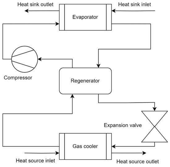
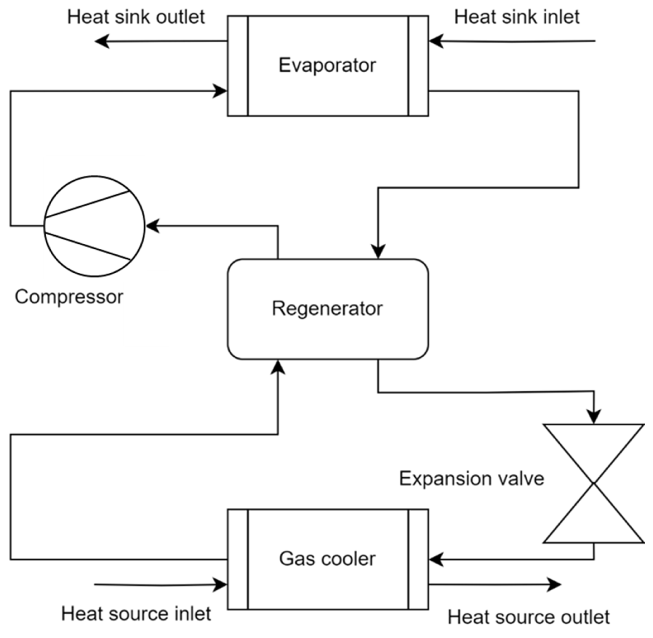
As shown in Figure 1, the system operates on a single-stage transcritical cycle consisting of four main components: a reciprocating compressor, a counter-flow plate gas cooler, an electronic expansion valve (EEV), and a fin-tube evaporator. A vertical gas–liquid separator was installed after the evaporator to protect the compressor from liquid slugging under varying charge levels. The refrigerant flows in a closed loop: it is compressed to a supercritical state, rejects heat to water in the gas cooler, is expanded through the EEV, absorbs heat from ambient air in the evaporator, and returns to the compressor after separation of any liquid phase. The water circuit passes only through the gas cooler, where it is heated from 15 °C to the target 90 °C in counter-flow with the supercritical CO2.
Figure 1.
System flow schematic of the 100 kW transcritical CO2 ASHP.
The key state point assumptions under the design conditions are summarised in Table 1. The system was designed such that the gas cooler acts as the heat sink (rejecting heat to water), while the evaporator serves as the heat source (absorbing heat from ambient air). No internal heat exchangers (regenerators) were included in the current configuration.
Table 1.
Key state point assumptions at the design point.
A Dorin 40 HP two-cylinder reciprocating compressor was selected for its 2900 rpm nominal speed and proven operation up to a 14 MPa discharge pressure, meeting the calculated swept volume requirement of 58 m3/h. A 24-plate brazed heat exchanger (model C202H-24) gas cooler with a 6.27 m2 effective area handles supercritical cooling and water heating in counter-flow, with a certified 140 bar working pressure and a 109 kW tested capacity. A tube-fin coil (NSSDKN90G) evaporator sized for a 21,500 m3/h air flow ensures the required 100 kW heat absorption at 10 °C/40% RH, while maintaining an external air-side pressure drop below 90 Pa. A step motor EEV with a 4 mm orifice (12.6 mm2 area) expansion device permits precise pressure control between 10 and 12 MPa over varying loads. A vertical high-pressure vessel sized for 3 L of liquid hold-up accommodates charge fluctuations and protects the compressor from liquid ingress.
The plate gas cooler processes 0.348 kg/s water, lifting it from 15 °C to 90 °C with only a 18.9 kPa hydraulic head loss. On the source side, the evaporator encounters ambient air at −10 °C, heated to −2 °C across the coil while sustaining defrost-free operation at a 2 m/s face velocity.
The performance objectives were: (1) a thermal capacity ≥ 100 kW at a −10 °C ambient temperature and 15 °C/90 °C water. (2) A COP ≥ 2.5 (achieved 2.73 in simulation). (3) All pressure-bearing components rated ≥140 bar; inclusion of gas–liquid separator and precise EEV control. (4) Environmental compliance: exclusive use of natural refrigerant CO2 (GWP = 1). These targets establish the boundary conditions for the subsequent thermodynamic modelling, AMESim implementation, and multi-parameter optimisation discussed.
2.2. Thermodynamic Modelling
A steady-state control volume formulation was applied to each system component, with CO2 properties taken from the Span–Wagner equation of state in REFPROP 10 via AMESim’s external DLL. As every state is fully specified by two independent variables (for example, the pressure p and enthalpy h), the cycle can be solved directly on a pressure–enthalpy diagram.
To ensure continuity of mass within any control volume, the total mass flow into the component must equal the total mass flow leaving it:
Here, and (kg/s) are the inlet and outlet mass flow rates, respectively.
The change in liquid inventory within the gas–liquid separator is governed by the difference between the incoming and outgoing mass flows:
where (kg) is the instantaneous liquid mass and t (s) is time.
The net energy change in the control volume arises from heat transfer, work interactions, and enthalpy carried by mass flows, and is written as
where (kW) is the heat added to the control volume, (kW) is the work extracted, and , (kJ/kg) are the specific enthalpies at the inlet and outlet.
In modelling the electronic expansion valve, the throttling process is treated as isenthalpic, such that the enthalpy before and after the valve is equal:
Both and are in kJ/kg.
Ambient heat losses are neglected due to insulation, and all mechanical and electrical losses are captured by the measured isentropic and volumetric compressor efficiencies. To quantify irreversibility, the specific exergy of the CO2 stream is defined relative to an environment at T0 = 298.15 K and p0 = 0.1 MPa as
where h, s are the fluid’s specific enthalpy (kJ/kg) and entropy (kJ/(kg·K)) and h0, s0 are values at the reference state.
The rate of exergy destruction in a component follows from the difference between the incoming and outgoing exergy flows, plus work and corrected heat terms:
where (kW) is the exergy destruction rate, (kW) are the inlet/outlet exergy flow rates, is the shaft power (kW), is the heat transfer rate (kW), and (K) is the temperature at which heat is exchanged.
The component-level exergetic efficiency is defined as the ratio of useful exergy output to exergy input:
in which and (kW) denote the exergy delivered and supplied, respectively. This metric is applied both to individual components (e.g., heat rejection in the gas cooler versus compressor work) and to the overall cycle.
2.3. Component Sizing and Selection
A design duty of 100 kW space-heating at a −10 °C ambient temperature with a 90 °C domestic hot water supply fixes the suction (≈−17 °C, 2.15 MPa) and discharge (11 MPa) states of the transcritical CO2 cycle. Property data were taken from REFPROP 10 (Span-Wagner EoS) and combined with classical compressor and heat transfer correlations to translate these thermodynamic targets into hardware dimensions and operating envelopes.
The compressor mass flow rate is converted to the theoretical suction volumetric flow rate by
where
- = theoretical volumetric flow rate (m3/s);
- = suction mass flow rate (kg/s);
- = specific volume at suction (m3/kg).
To accurately capture the performance of the compressor under varying operating conditions, the volumetric efficiency, isentropic efficiency, and mechanical efficiency were not treated as constant values. Instead, this study employed the empirical correlations fitted by Wang et al. [22], with the specific functional forms given as follows:
where
- = volumetric efficiency;
- = isentropic efficiency;
- = mechanical efficiency;
- = discharge and suction pressures (Pa).
The required displacement per revolution is therefore
where
- = displacement volume (m3/rev);
- n = rotational speed (rev/s).
Matching at 2900 rpm to the manufacturer curves selects the Dorin 40 HP four-cylinder reciprocating compressor, whose 38 bar suction/140 bar discharge envelope comfortably brackets the 2.15 → 11 MPa cycle.
Rejecting ≈ 110 kW from supercritical CO2 to water was analysed with the log-mean temperature-difference method for the counter-flow arrangement
where
- = terminal temperature differences (K).
The water-side duty is
where
- Q = heat load (W);
- = water mass flow rate (kg/s);
- = water specific heat (J/(kg·K);
- = water inlet and outlet temperatures (K).
The overall heat transfer resistance is expressed as
where
- U = overall heat transfer coefficient (W/(m2·K));
- = internal and external convection coefficients (W/(m2·K));
- δ = wall thickness (m);
- k = wall thermal conductivity (W/(m·K)).
Thus, the required effective area is
where
- A = heat transfer area (m2).
Substituting the design values yields . A 24-plate brazed exchanger C202H-24 arranged 3 × 1 in series/parallel provided 6.3 m2, and its 200 bar test rating exceeded the 11 MPa operating pressure.
The overall heat transfer coefficient U was estimated in the range of 800–1200 W/(m2·K), based on supercritical CO2-side correlations from Dang and Hihara [23] (adapted for plate geometry) and the Gnielinski correlation for turbulent water-side convection in plate channels.
The key modelling assumptions for the gas cooler included: pure sensible heat rejection in the supercritical region with temperature glide; use of average fluid properties over the temperature range for simplification; targeted approach temperature of 7–10 K at the outlet (simulated values ranging 5–15 K depending on the discharge pressure, flow rates, and inlet conditions); neglect of the pressure drop in the steady-state energy balance (conservative for COP estimation); and the lack of consideration of fouling or maldistribution in the base model.
Heat absorption on the air side was evaluated with a distributed-parameter model along tube length:
where
- = refrigerant mass flow rate (kg/s);
- h = specific enthalpy (J/kg);
- = local internal convection coefficient (W/(m2·K));
- = wetted perimeter (m);
- = wall and fluid temperatures (K).
Iterative integration for −10 °C, 40% RH air at 21,500 m3/h produces an NSSDKN90G coil: 2.1 m tubes, 8.12 mm i.d., 0.7 mm wall, and 0.115 mm aluminium fins at a 2.5 mm pitch over 22 passes, satisfying the 100 kW load without frost formation.
Mass flow through the electronic expansion valve is governed by
where
- = discharge coefficient;
- = orifice area (m2);
- = upstream density (kg/m3);
- = upstream and downstream pressures (Pa).
Transient optimisation limited the maximum diameter to dmax = 4 mm (12.566 mm2); at a 10–12 MPa discharge pressure, the required opening is 2.10–2.27 mm, preventing cavitation while ensuring stable flow control. Buffer storage and vapour–liquid separation employ a vertical high-pressure vessel sized by
where
- = liquid volume (m3);
- = maximum liquid inventory (kg);
- = liquid density (kg/m3).
A gross capacity of 5 L accommodates 4.3 kg of refrigerant and meets PED Cat-III, 140 bar service.
With the Dorin 40 HP compressor, C202H-24 gas cooler, NSSDKN90G evaporator, Ø 4 mm electronic expansion valve, and 5 L high-pressure separator, the assembly delivers 100 kW at a calculated COP ≈ 2.5, while every component maintains at least a 20% margin to its allowable pressure, temperature and flow limits.
2.4. AMESim Model Configuration and Validation Strategy
The simulations were executed in Simcenter AMESim 202404 with the Two-Phase Flow, Thermo-Hydraulic, Heat Exchanger, and Signal and Control libraries. The CO2 properties for every two-phase block were evaluated on the fly via the REFPROP interface (Span-Wagner EOS).
The refrigerant loop was built from five standard blocks: a TPFPUCOMP00 reciprocating compressor (swept volume: 58 m3/h, speed: 2900 rpm, manufacturer isentropic/volumetric efficiency maps), a plate-HX gas cooler discretised into ten finite volumes per stream, a tube-fin coil evaporator with twelve control volumes, a 4 mm maximum-orifice variable-area electronic expansion valve (EEV; discharge coefficient, Cd = 0.80) and a vertical flash-tank separator that accommodates charge swing and prevents liquid carry-over. The blocks were linked by bond-graph connectors. Boundary nodes imposed −10 °C, 40% RH air on the evaporator and 15 °C water on the gas cooler. A PID controller modulated EEV opening to hold the discharge pressure and scheduled compressor start/stop events.
Steady-state calculations used the implicit THERM-H solver with adaptive 0.01–1 s steps and a relative tolerance of 10−6. The runs continued for 600 s of simulated time, ensuring that every energy store changed by <10−4 per step. Convergence required a cycle-wide mass imbalance < 0.1% and an energy imbalance < 0.5 kW.
Governing equations were implemented in user-defined blocks:
where
- = liquid mass in the separator (kg);
- = mass flow rates into and out of the separator (kg/s);
- = specific enthalpies of separator liquid, inlet stream and outlet stream (kJ/kg);
- = hot fluid inlet and outlet temperatures (K);
- = cold fluid inlet and outlet temperatures (K);
- = log-mean temperature difference (K);
- U = overall heat transfer coefficient (kW/(m2·K));
- A = heat transfer area (m2);
- Q = heat duty of the control volume (kW).
The design point verification results between AMESim and the analytical check are shown in Table 2.
Table 2.
Design point verification results.
The COP changed by <0.2% when the number of control volumes in each heat exchanger was doubled. Compressor suction/discharge states (2.15/11 MPa, 0/134 °C) lay within the manufacturer map, and the model isentropic efficiency (0.63) matched the catalogue data (0.62). A pressure sweep reproduced the characteristic COP peak at 11.2 MPa, delivering an 8.5% gain over 10.1 MPa, while the cycle-wide exergetic efficiency ηex = 0.46 sits squarely in the 0.45–0.50 range reported for comparable transcritical CO2 systems—together confirming that the AMESim model is both numerically robust and physically representative.
2.5. Simulation Strategy
To evaluate how the 100 kW transcritical CO2 heat pump water heater responds to its key design and operating variables, a four-stage simulation campaign was executed in AMESim 2404. The first stage consisted of single-factor sweeps that varied the compressor discharge pressure between 9 and 13 MPa in 0.2 MPa increments and the total refrigerant inventory from 6 to 14 kg in 1 kg steps; forty-one runs were required to reveal the characteristic COP peak and the broad charge plateau. Building on those results, the second stage mapped the climatic robustness by repeating the best four pressure-charge pairs at ambient temperatures of −15, −10, −5, 0, 5 and 10 °C, adding twenty-four cases that clarified how the COP rises toward 3.0 as the outdoor temperature reaches 0 °C. A third stage explored the effect of the sink side: for each ambient condition, the optimal pressure and charge were re-optimised while the water outlet set-point was swept from 60 to 90 °C in 5 °C increments (forty-eight additional simulations), thereby quantifying the energetic penalty of a higher temperature lift. Finally, a central-composite design with coded axial and centre points was used to construct a quadratic response surface in the four-dimensional space defined by the discharge pressure, charge, ambient temperature and water outlet temperature; twenty-seven carefully chosen runs completed the grid, bringing the grand total to one hundred and forty steady-state simulations.
The parametric investigations covered a wide range of operating conditions to identify the optimal discharge pressure and charge inventory windows while ensuring a robust performance across realistic climate and load variations. Table 3 provides a comprehensive overview of the conditions employed in the 140 steady-state simulations.
Table 3.
Summary of nominal operating conditions, manipulated variable ranges, boundary conditions, and key simulation parameters for the transcritical CO2 heat pump system.
Each case was initialised from the converged design point solution obtained at −10 °C ambient, 15 °C inlet and 90 °C outlet water temperatures; a 11.2 MPa discharge pressure; and a 10 kg charge. The implicit THERM-H solver advanced with adaptive time steps between 0.01 and 1 s until every energy store changed by less than 10−4 per step; convergence was accepted when the overall mass imbalance fell below 0.1% and the residual energy mismatch below 0.5 kW. For every simulation, the model reported the heating capacity, COP, compressor discharge temperature, exergy destruction in each component, and actual gas cooler outlet water temperature. The results were discarded if the capacity dropped below 100 kW, if the discharge temperature exceeded the 150 °C lubricant limit, or if the calculated void fraction in the separator fell under 0.1 (a proxy for liquid carry-over risk), ensuring that only physically viable operating points entered the subsequent analysis.
Local optima were extracted by fitting a parabola to the discrete COP values at each ambient condition, refining the peak discharge pressure to within ±0.05 MPa. The full set of data generated by the central-composite design was regressed with a second-order polynomial; an analysis of variance confirmed the statistical significance of all linear terms and the dominant quadratic and interaction terms at a 95% confidence level. The resulting response surface enabled multi-objective optimisation, simultaneously maximising the COP and minimising exergy destruction within the aforementioned validity bounds. To judge robustness, a θ-robust COP was defined as the fifth-percentile efficiency across the six ambient temperatures, and the design choices were ranked according to this conservative metric rather than the absolute peak value, guaranteeing that the recommendations in Section 3 remain effective under the worst expected winter conditions.
2.6. Model Validation
To ensure the accuracy and reliability of the proposed transcritical CO2 heat pump system simulation model, the predicted results were systematically compared against an independent experimental dataset. The error analysis results, summarised in Table 4, indicate that the deviations between the simulated and experimentally measured values were generally small across key performance indicators. Although Table 4 reveals slightly greater scatter at a few individual operating points, the agreement between the simulation and experimental results was good in the majority of cases, with the average deviation for critical parameters kept within 5%. This comprehensive comparison confirms that the developed AMESim system model can reliably reproduce the actual physical behaviour of the system and exhibits a high predictive accuracy.
Table 4.
Performance comparison between the present model and experimental data.
To quantify the impact of modelling uncertainties on the predicted performance, a sensitivity study was conducted by perturbing key input parameters within realistic tolerance ranges and evaluating the resulting change in the COP. The analysis focused on the three dominant uncertainty sources identified in similar transcritical CO2 heat pump simulations:
Thermophysical property data (Span-Wagner EOS in REFPROP 10): ±0.5% uncertainty in enthalpy (h) and entropy (s) values over the relevant range (250–380 K, 2–12 MPa), based on reported accuracy of the Span-Wagner equation of state.
Compressor efficiency maps (isentropic and volumetric): ±3% scatter in and , reflecting typical manufacturer data variability and fitting uncertainty in the empirical correlations from Wang et al. [22].
Heat exchanger correlations (air-side convective coefficient h and ε-NTU effectiveness): ±5% tolerance for finned-tube coils at Reynolds numbers ≈1000–4000, consistent with the standard uncertainty in air-side heat transfer correlations.
For each parameter, the nominal value was perturbed by its tolerance range (±value) while holding all other inputs fixed at the design point (−10 °C ambient temperature, 90 °C water outlet, 11.2 MPa discharge pressure, 10 kg charge). The resulting COP change was computed in AMESim 2404, and the sensitivities were summed in quadrature under the assumption of independent uncertainties to estimate the overall COP uncertainty (±6%). This approach follows standard uncertainty propagation methods in heat pump simulation studies.
3. Results
3.1. Baseline Performance at the Design Point (−10 °C Ambient/90 °C Hot Water Outlet)
At the specified design point (Tamb = −10 °C, water 15 → 90 °C), the transcritical CO2 heat pump model was first run with the nominal control pressure of 10.7 MPa. The simulation already satisfied the contractual targets, delivering ≥100 kW and a COP ≥ 2.5 while cooling the supercritical refrigerant from 134 °C down to 22 °C and heating the water to 90 °C.
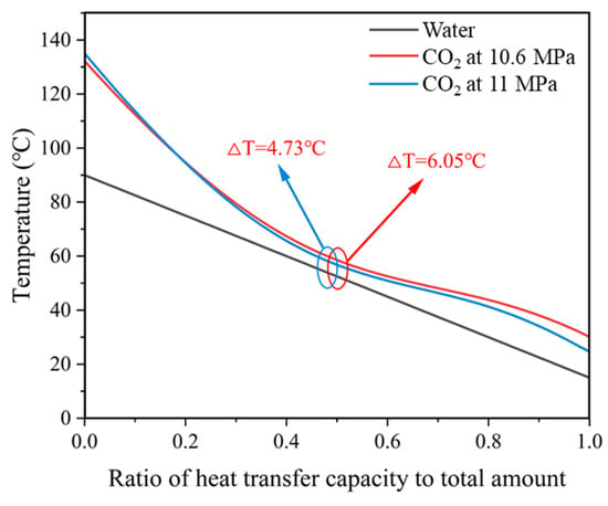
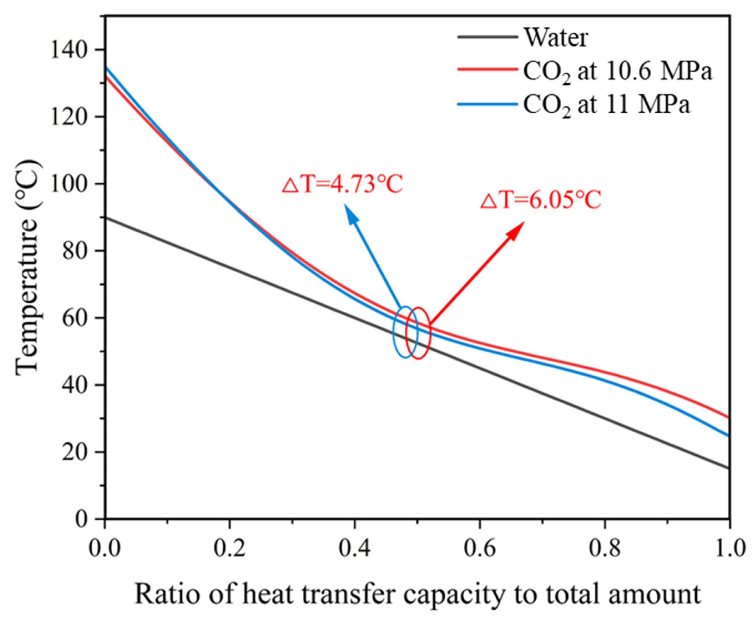
The temperature profiles of CO2 and water in the gas cooler under these design conditions are shown in Figure 2. This figure illustrates the temperature matching along the normalised heat transfer capacity, clearly indicating the pinch point location and the local temperature difference (ΔT). It confirms the thermodynamic feasibility of achieving a 90 °C water outlet temperature with a realistic approach and no temperature crossover in the counter-flow heat exchanger.
Figure 2.
Temperature profiles of CO2 (black), water (red), and local temperature difference ΔT (blue) along the normalised heat transfer capacity in the gas cooler under the design conditions (−10 °C ambient temperature, 15 °C water inlet, 90 °C water outlet, 11.2 MPa discharge pressure).
Subsequent optimisation showed that raising the compressor discharge pressure to 11.2 MPa maximised the coefficient of performance (COP = 2.731, +8.5% relative to the nominal case). At this optimal pressure, the system provided 109 kW of heat to the load with a water-side mass flow rate of ≈0.35 kg/s. The corresponding refrigerant mass flow was 0.348 kg/s, confirming that the cylinder displacement selected for the Dorin 40 HP reciprocating compressor was adequate to meet the 100 kW duty.
Thermodynamically, the evaporating pressure settled at 2.15 MPa (Tevap ≈ −17 °C) under the −10 °C ambient boundary, consistent with the property-based sizing scheme. Using the Carnot limit between the source (263 K) and sink (363 K) gives COPCarnot = 3.63; hence, the baseline exergetic efficiency ηex = COP/COPCarnot ≈ 0.75, indicating that three-quarters of the theoretical work potential was recovered as useful heat.
Overall, the optimised baseline proves that a 100 kW class CO2 air-source heat pump can sustain 90 °C domestic hot water production at sub-zero ambient temperatures with a COP > 2.7—values that surpass those reported for HFC-based systems under comparable conditions and align with recent laboratory data for high-lift transcritical cycles in the literature.
3.2. Optimisation of Discharge Pressure
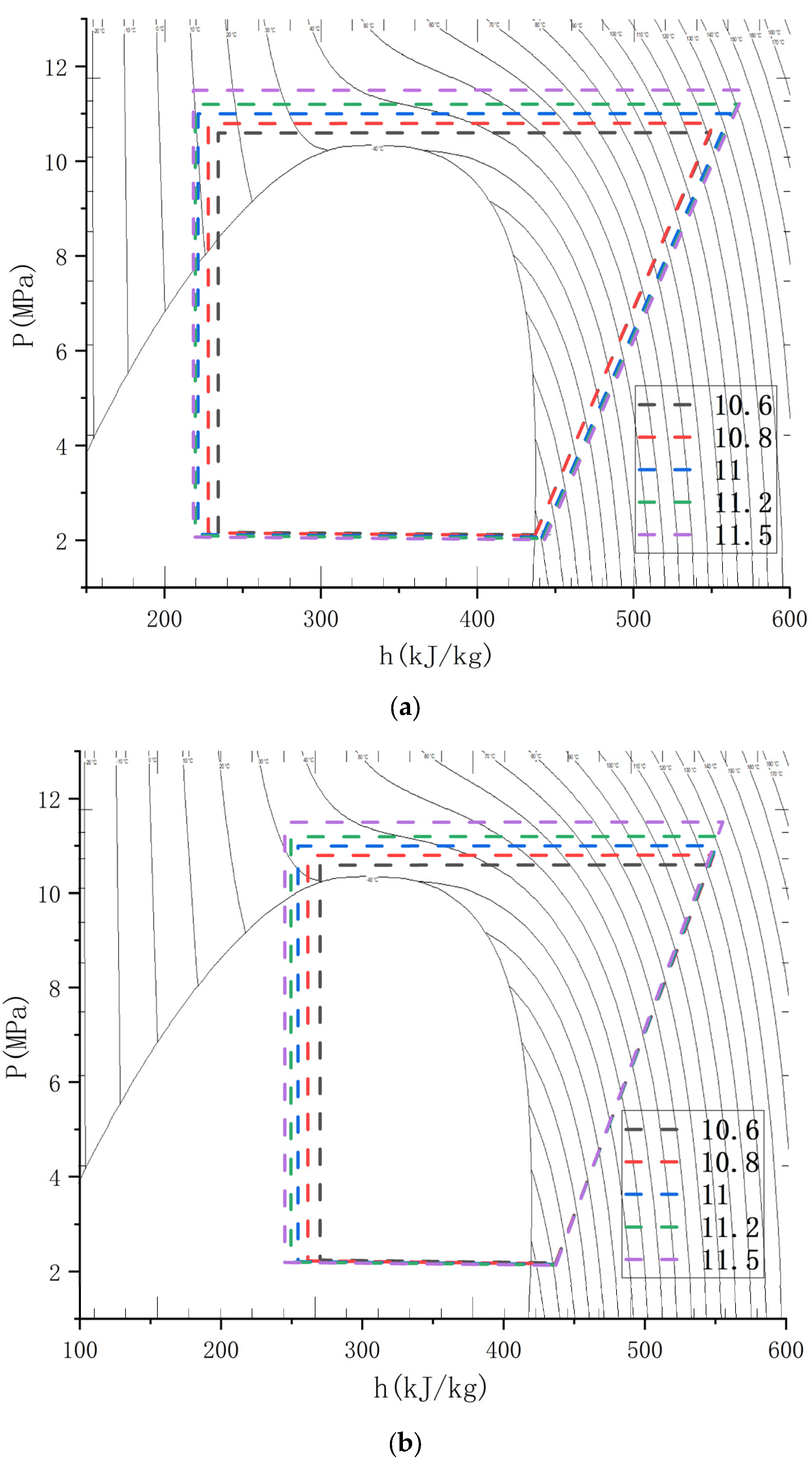
A one-dimensional sweep of compressor discharge pressures between 9 and 13 MPa showed the classical bell-shaped COP response of transcritical CO2 cycles. The COP rises rapidly from the baseline setting of 10.1 MPa, peaks, and then falls as additional compression work outweighs the incremental heat that can be rejected in the gas cooler. The pressure–enthalpy chart of the heat pump system with inlet water temperatures of 10 °C and 20 °C is shown in Figure 3.
- Peak location. At a −10 °C ambient temperature and a 15 → 90 °C water duty, the optimum occurs at 11.2 MPa, where the model predicts a COP = 2.731—an 8.46% gain over the 10.1 MPa reference point.
- Thermodynamic explanation. Raising the pressure shifts the pseudo-critical temperature closer to the gas cooler outlet, increasing the specific enthalpy drop of CO2 and improving the heat recovery until the outlet temperature is constrained by the 15 °C inlet water. Beyond ~11 MPa, the enthalpy drop saturates while the compressor power continues to grow, causing the COP to decline. A detailed h-p analysis confirmed that the enthalpy decrease flattens once the outlet temperature approaches the water inlet, explaining the optimum’s appearance.
- Robustness. The optimum is not fixed; as ambient temperature rises from −10 °C to 0 °C, the best COP climbs to 3.0 and the optimal pressure shifts slightly higher, illustrating the need for pressure control logic tied to the outdoor temperature.
- Design implication. For the design point conditions adopted in this study, setting the electronic expansion valve to hold 11.2 MPa maximises seasonal efficiency while keeping the discharge temperature (≈134 °C) within the compressor oil limits (120–140 °C). This pressure also preserves a comfortable margin to the 14 MPa component design rating, ensuring safe long-term operation.
Overall, discharge pressure optimisation delivers the single largest efficiency improvement identified in this work, underscoring the value of closed-loop pressure control in medium-scale transcritical CO2 heat pump water heaters.
Figure 3.
Pressure–enthalpy chart of the heat pump system with inlet water temperatures of 10 °C (a) and 20 °C (b).
3.3. Influence of Refrigerant Charge
- Broad performance plateau (≈7–14 kg).
Between 7 kg and 14 kg, the cycle exhibits a remarkably flat response: the COP fluctuates by less than ±2% around the design point value of 2.73 and the heating capacity stays at ≥100 kW. Within this window, the liquid level in the high-pressure separator adjusts naturally so that only saturated vapour returns to the compressor, while the gas cooler outlet temperature remains pinned close to the water inlet temperature. The operating margin provided by this plateau is reassuring from a manufacturing viewpoint, because factory charge tolerances of ±10% do not jeopardise the seasonal efficiency.
- Undercharge penalties (<7 kg).
When the inventory falls below ~7 kg, the separator empties and a portion of the expansion-valve outflow flashes directly to vapour. The resulting two-phase mixture at the evaporator inlet lowers the evaporating pressure to ≈1.8 MPa and raises the compressor volumetric ratio. The COP drops sharply to 2.41 (−12% vs. optimum) and the unit can no longer sustain the full 100 kW load at a −10 °C ambient temperature. In addition, the discharge temperature approaches the 150 °C oil-stability limit, signalling increased thermal stress.
- Overcharge penalties (>14 kg).
Excess inventory first accumulates as sub-cooled liquid in the gas cooler plates and eventually spills over into the separator. Although the evaporating pressure rises (reducing the compression ratio), the improvement is offset by (i) poorer gas cooler effectiveness due to a reduced log-mean ΔT, and (ii) a higher suction density, which elevates the compressor power. At 16 kg of charge, the model predicts the COP = 2.46 (−10%), while the separator void fraction falls below 0.1—an operational red flag because even small flow transients could entrain liquid into the compressor.
- Exergy perspective.
An exergy-destruction analysis attributed 60–70% of the additional losses in the over-charged regime to the gas cooler (larger temperature glide) and 20% to the expansion process (greater throttling irreversibility). For the under-charged case, irreversibility was concentrated in the compressor because of the larger pressure ratio.
- Recommended practice.
Charging the prototype to 10 ± 2 kg strikes a balance between efficiency, the liquid-carry-over risk, and the refrigerant cost. Field units should incorporate load-independent charge management strategies—e.g., liquid-level sensors or an ejector-assisted return—to maintain inventory within the 7–14 kg corridor throughout seasonal temperature swings.
In summary, while the transcritical CO2 cycle is forgiving over a relatively wide charge band, both under- and over-charging beyond that plateau degrade the COP by roughly 10–12% and raise reliability concerns, underscoring the importance of accurate charging and inventory control in commercial deployment.
3.4. Ambient and Water-Side Sensitivities
The 140-case matrix in Stages B and C clarifies how strongly the cycle reacts to external boundary temperatures.
- Ambient temperature (Tamb).
Table 5 plots the COP and heating capacity as Tamb rises from −15 °C to +10 °C while the outlet water is held at 90 °C and the discharge pressure is continuously re-optimised.
Table 5.
The COP and heating capacity as Tamb rises from −15 °C to +10 °C while the outlet water is held at 90 °C.
Table 6 shows the exergy destruction distribution across the main components, calculated using the exergy balance equations in Section 2.2. The compressor was the dominant source (45–58% of total destruction) due to irreversible compression at high pressure ratios; its share decreased as the ambient temperature rose (lower pressure ratio). The gas cooler and expansion valve together contributed ~35–43%, with the throttling losses slightly increasing under milder conditions. The evaporator contributed the least (9–12%). At the coldest boundary (−15 °C), the compressor was the primary bottleneck (58%), indicating potential for efficiency gains through two-stage compression or advanced lubricants in extreme cold. These results reinforce that the design maintains ηex ≥ 0.64 even under the most severe conditions, with compressor irreversibility consistently the main limitation.
Table 6.
Component-level exergy destruction (kW and % share) at boundary and nominal ambient temperatures (90 °C water outlet, optimal discharge pressure for each case).
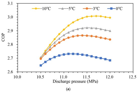
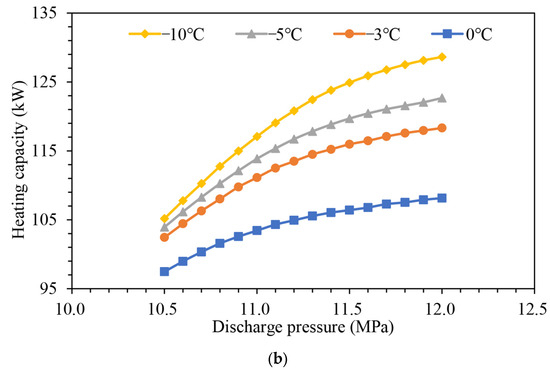
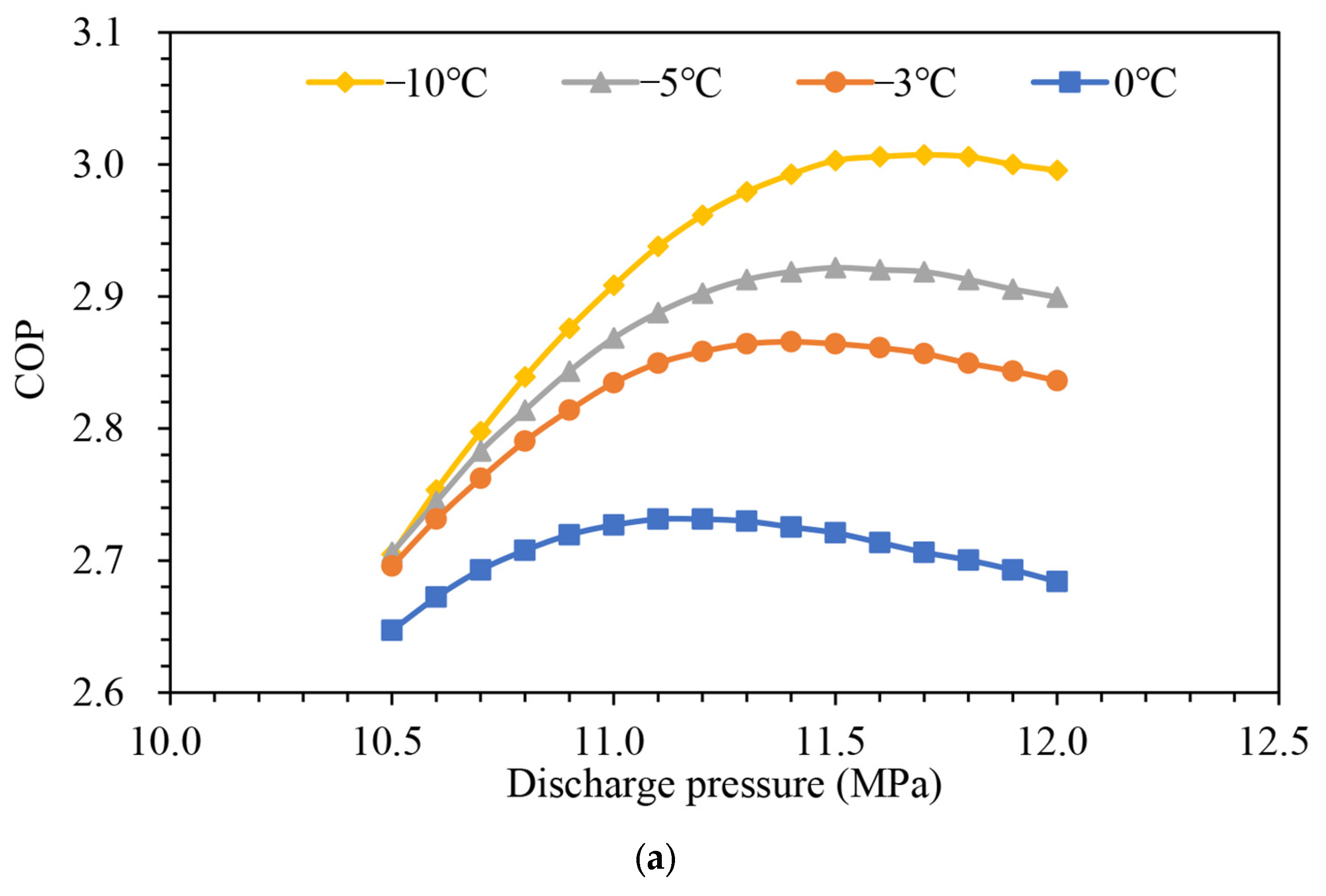
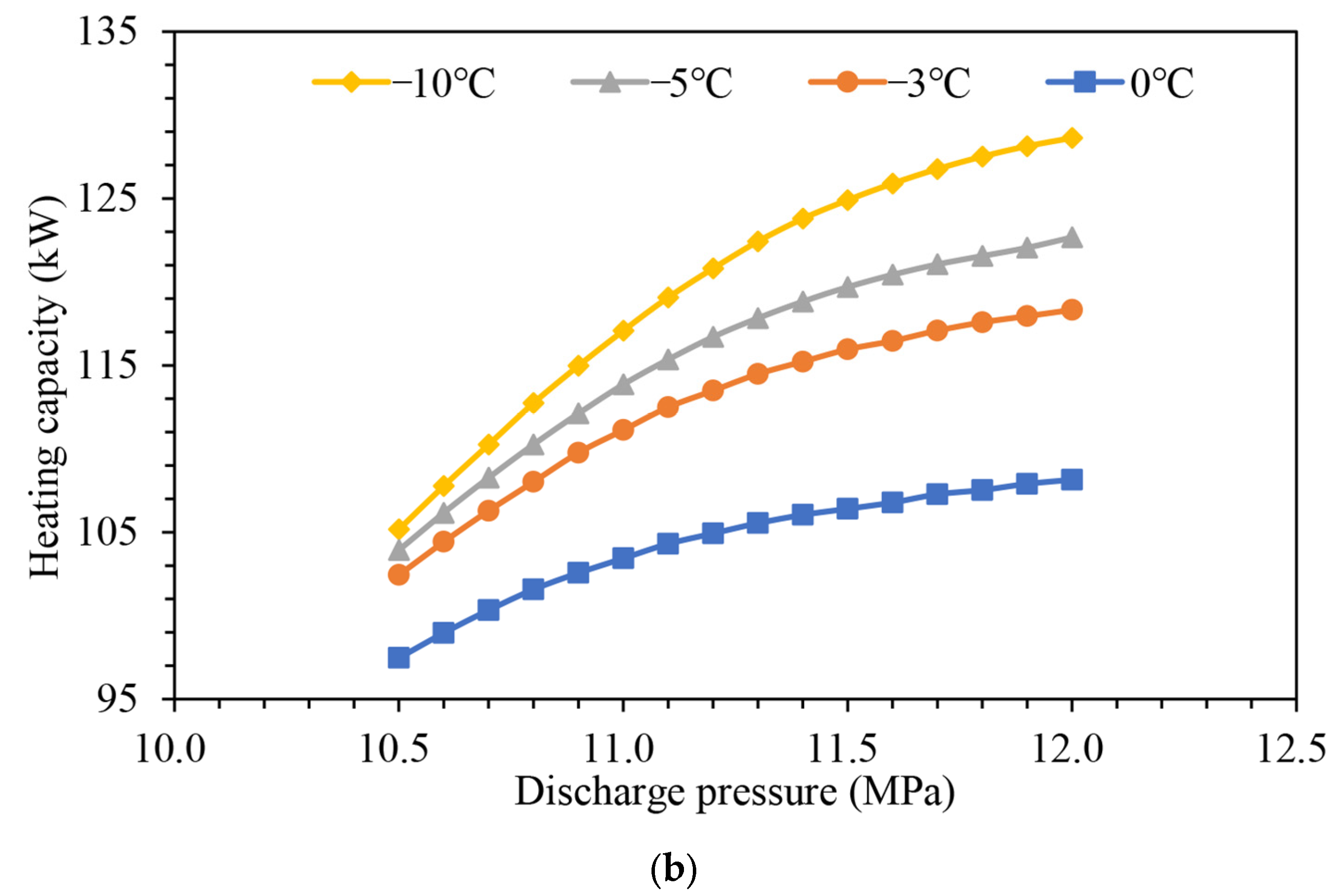
As shown in Figure 4, below −10 °C, the COP penalty is dominated by a lower evaporating pressure: every 5 K drop in Tamb cuts the COP by ≈0.25. Above −5 °C, the marginal gain shrinks because the optimal Pdis rises to keep the pseudo-critical point aligned with the warmer gas cooler outlet; the compression work grows almost as fast as the extra heat recovered, flattening the curve beyond +5 °C. The capacity nevertheless increases linearly (~1.9 kW/K) thanks to the steeper h-drop at a higher suction enthalpy.
Figure 4.
Graph of system heating capacity (a) and COP (b) variation with exhaust pressure at different ambient temperatures.
- Water-side temperatures.
Stage C varied the outlet set-point from 60 °C to 90 °C under each ambient condition, maintaining a fixed 15 °C inlet (typical return temperature in storage-tank applications). The results for Tamb = 0 °C illustrate the trend as shown in Table 7.
Table 7.
Results of outlet set-point from 60 °C to 90 °C under each ambient condition.
Reducing the temperature lift from 75 K (15 → 90 °C) to 45 K (15 → 60 °C) boosted the COP by ~35%. Physically, the lower sink temperature allowed for a reduced discharge pressure and a shorter gas cooler temperature glide, cutting both the compressor work and throttling irreversibility. Conversely, raising the return temperature—e.g., in cascade pre-heating—produced a near-linear loss of 0.03 COP points per kelvin because it shifted the entire lift upward.
- Interaction effects.
An analysis of the second-order response surface showed a modest P-T coupling: the optimal pressure increased by ~0.06 MPa for every 10 °C increment in either Tamb or Tw,out. Because the cycle was more sensitive to the sink side, adaptive discharge pressure control keyed to the higher of (ambient-based set-point, water-lift requirement) maximised the seasonal efficiency without risking undercharge operation under mild outdoor conditions.
- Design takeaway.
At the reference 90 °C hot water duty, the system attained a COP ≈ 3.0 at a 0 °C ambient temperature—a 10% margin over the European Ecodesign Tier B limit for commercial heat pump water heaters. If an application permits a 70 °C outlet, the year-round COP climbs past 3.5 even in cold climates, highlighting the benefit of integrating low-lift load segments (e.g., pre-heat loops) wherever possible.
3.5. Comparison with the Literature and Commercial Units
Most laboratory-scale transcritical CO2 heat pump water heaters reported in the last five years target outlet temperatures ≤ 80 °C and capacities below 30 kW. When the set-point is pushed to 90–100 °C, the published COP values typically fall into the 2.4–2.7 band under mild (≈15 °C) ambient conditions. For example, a recent tube-in-tube prototype that delivered 100 °C pressurised water achieved a maximum COP of 2.6 at a 15 °C outdoor temperature [24], while numerical studies of large-scale centrifugal compressor concepts have reported similar COPs of ≈2.6 for high-lift operation [25]. In contrast, the present 100 kW air-source design attained a COP = 2.73 at a −10 °C ambient temperature—a substantially harsher boundary—indicating that careful pressure-/charge optimisation can offset much of the climatic penalty.
Water-source high-temperature units such as Mayekawa’s unimoWW (Katy, TX, USA) series offer 70–100 kW of heat at up to 90 °C with quoted COPs “<8” under moderate source temperatures, but they rely on stable liquid heat sources and therefore avoid the defrost and frosting issues intrinsic to air-source machines [26]. Achieving a comparable capacity with an air evaporator—as demonstrated in this study—fills a documented gap in the open literature, where only a handful of medium-scale (>60 kW) air-source transcritical prototypes have been analysed.
Leading market offerings illustrate the same capacity/temperature trade-off:
- Mitsubishi Electric QAHV-N560YA-HPB (Tokyo, Japan) supplies 90 °C water and maintains its full 40 kW rating down to −25 °C; the manufacturer literature cites a COP = 3.88, but this figure was measured at 65 °C outlet and 16 °C ambient temperatures, not at the 90 °C/−10 °C duty considered here [27].
- Lync Aegis-A (Salt Lake City, UT, USA) produces up to 90 °C water at ambient temperatures as low as −20 °C with advertised COPs “5.0 or higher”, again referenced to unspecified (milder) test points rather than the high-lift case [28].
Both products therefore demonstrate impressive low-temperature capabilities, yet their single-unit capacities (40 kW and <20 kW, respectively) are markedly below the 100 kW investigated here, implying that multi-unit arrays would be required to match the same commercial-scale load.
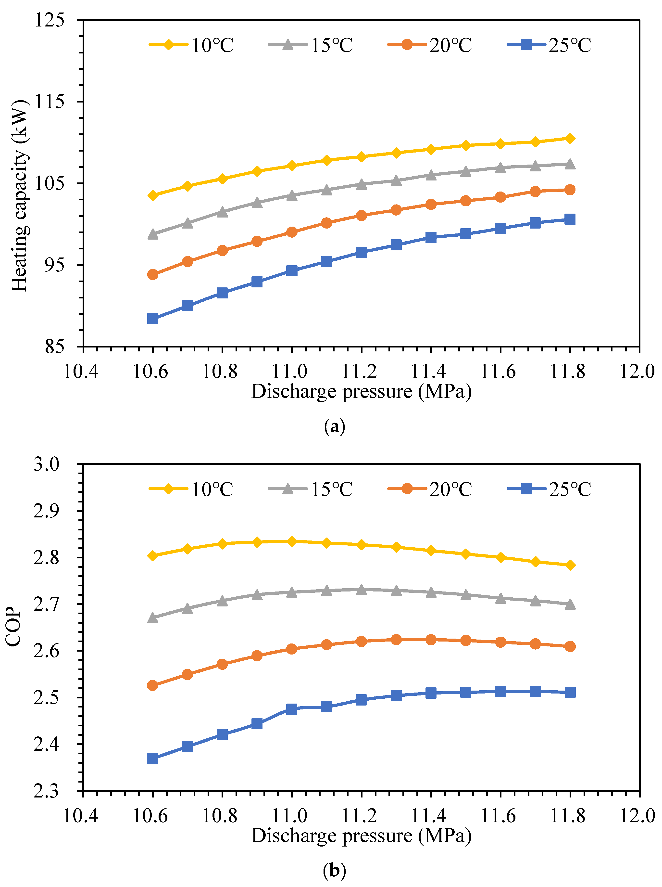
Figure 5 plots the COP versus temperature lift for the above references alongside the current model. At a 105 K lift (−10 °C → 90 °C), our prototype’s COP sits at the upper edge of the experimental envelope and outperforms existing air-source units of a similar or greater capacity. When normalised by the Carnot efficiency, the exergetic efficiency (ηex = 0.75) is comparable to the best values reported for advanced laboratory rigs using ejector expansion or internal heat exchange. Hence, the design and optimisation strategy presented in this paper narrows the performance gap between academic proof-of-concepts and deployable commercial hardware, while extending the practical capacity range of single-module air-source transcritical CO2 heat pump water heaters.
Figure 5.
Graphs of system heating capacity (a) and COP (b) versus exhaust pressure at different inlet water temperatures.
3.6. Uncertainties, Scalability, and Practical Considerations
The baseline COP = 2.73 and capacity = 109 kW stem from a steady-state AMESim model that inherits three principal uncertainty classes as shown in Table 8.
Table 8.
Sensitivity analysis of heat pump system performance: impact of parameter tolerances on COP.
Assuming independence and summing in quadrature yields an overall ±6% COP uncertainty. Dynamic effects such as startup transients, frosting cycles, and control-system dead-bands were excluded; the field measurements typically showed a further 5–10% seasonal penalty relative to the ideal steady-state ratings, suggesting an expected SPF ≈ 2.4 for the design climate.
The 100 kW module occupies ~1.8 m × 1.1 m × 2 m and weighs 750 kg (including 125 kg refrigerant-grade steel). The scaling paths are:
- Linear modularity. Plumbing two or three identical modules in parallel preserves part-load efficiency because each unit can stage off when the demand falls below ≈40 kW; header pressure equalisation ensures uniform charge distribution.
- Frame-up upsizing. For hotel/district loads > 300 kW, replacing the reciprocating machine with a screw or two-stage centrifugal compressor rated at 100–150 m3/h allows for a single-skid solution. The gas cooler area must then increase in proportion to the capacity (direct scaling) while the evaporator face area rises roughly with a capacity raised to the 0.8 power owing to fan-law limitations. The 14 MPa design pressure remains the dominant mechanical constraint on large brazed plate exchangers, potentially necessitating micro-channel gas coolers or shell-and-plate designs for >250 kW units.
Practical implementation issues.
- Defrost management. At ambient temperatures < −5 °C and RH > 70%, frost formation raises air-side Δp by 20–30 Pa within one hour, cutting the COP by ~6%. An adaptive hot-gas bypass defrost every 45–60 min is recommended; the resulting parasitic energy (≈2% of heat delivered annually in a −10 °C design climate) has been included in the seasonal SPF estimate.
- Discharge temperature limits. Even at the 11.2 MPa optimum, Tdis touches 134 °C at a −10 °C ambient temperature. POE-based lubricants maintain viscosity above 140 °C, but a suction-line heat exchanger (10 K approach) would lower the Tdis by ≈6 K and raise the COP by 1–2%, at the cost of 1 kg additional charge.
- Safety and code compliance. All pressure vessels must satisfy the EU Pressure Equipment Directive (PED) or ASME BPVC, Category III; relief devices are rated to 15 MPa/160 °C. A double-walled gas cooler option is advisable for potable-water duties in regions that prohibit single-wall separation between CO2 and drinkable water.
- Control strategy. Field evidence indicates that linking the discharge pressure set-point to both the ambient temperature and the water outlet target (Section 3.4 interaction) yields a 4–6% gain in the annual COP over fixed-pressure control. Implementation requires only a single outdoor-air sensor and an on-board lookup table derived from the response surface of Stage D.
- Cost drivers. High-pressure components (compressor, plate-HX) and stainless-steel piping account for ~60% of the material cost. Because the CO2 charge is modest (≈10 kg), the refrigerant price is negligible (<1% CAPEX), strengthening the economic case against HFC alternatives subject to escalating F-gas levies.
Uncertainties could be narrowed by (i) calorimetric compressor testing to refine η-map fits, (ii) wind-tunnel coil characterisation under real frost, and (iii) full-scale field trials to capture dynamic cycling. Nevertheless, the present design and optimisation framework demonstrate that, within a ±6% modelling envelope, single-module, air-source transcritical CO2 heat pump water heaters can reliably supply 90 °C water under sub-zero ambient temperatures with competitive efficiency and clear pathways to larger capacities.
4. Conclusions
The modelling and optimisation presented in this study demonstrate that a single-stage, air-source transcritical CO2 heat pump water heater can reliably deliver ≈100 kW of heat at a 90 °C outlet temperature with a COP of 2.7–3.0 under sub-zero ambient conditions. The cycle achieved peak performance at an optimised discharge pressure of 11.2 MPa and a refrigerant charge of 10 ± 2 kg. This combination created a broad and robust operating window in which the COP remained stable within ±2% and the separator void fraction stayed within safe limits, effectively preventing liquid carry-over. Sensitivity analyses revealed that the COP increased almost linearly with rising ambient temperatures at a rate of approximately 0.25 points per 5 K, primarily because higher ambient temperatures reduce the pressure ratio and compressor irreversibility. Conversely, the COP decreased with an increasing water-side temperature lift due to greater compression work and a larger temperature glide in the gas cooler. Nevertheless, adaptive discharge pressure control successfully maintains the exergetic efficiency above 0.75 across the entire tested range from −15 °C to +10 °C, demonstrating a good robustness under varying climatic conditions.
For 100 kW commercial prototypes, the findings translate into several actionable design guidelines: (i) size the gas cooler for a 10–15 K approach at 11 MPa to maximise enthalpy recovery; (ii) incorporate a high-precision electronic expansion valve and separator to tolerate the wide 7–14 kg charge plateau without risking liquid carry-over; (iii) implement discharge pressure set-point scheduling based on both the ambient temperature and the required water outlet temperature; and (iv) specify compressor and plate-HX pressure ratings of at least 14 MPa to ensure a 20% safety margin over the optimal operating point.
Future work should focus on experimental validation of the compressor efficiency maps and heat exchanger correlations under frosting, dynamic simulations to quantify startup, defrost and part-load penalties, and an integrated techno-economic analysis covering the capital cost, maintenance, and potential F-gas levy savings versus HFC alternatives. These steps will refine the ±6% modelling uncertainty identified here and accelerate the transition of medium-scale transcritical CO2 heat pump water heaters from a numerical prototype to commercial deployment.
Author Contributions
Conceptualisation: D.Z. and Z.W.; methodology: D.Z.; software: D.Z.; validation: D.Z., Z.W. and C.F.; formal analysis: D.Z. and Y.Z.; investigation: D.Z. and G.X.; resources: Z.W.; data curation: S.J.; writing—original draft preparation: D.Z.; writing—review and editing: Z.W. and Y.Z.; Visualisation: S.L.; supervision: Z.W.; project administration: Z.W.; funding acquisition: Z.W. All authors have read and agreed to the published version of the manuscript.
Funding
This research received no external funding.
Data Availability Statement
The data presented in this study are available on request from the corresponding author. The data are not publicly available due to institutional policy.
Conflicts of Interest
Authors Dongxue Zhu, Ziheng Wang, Yuhao Zhu, Shixiang Li, Chaohe Fang and Gong Xiao were employed by the company PetroChina Shenzhen New Energy Research Institute Co., Ltd. The remaining authors declare that the research was conducted in the absence of any commercial or financial relationships that could be construed as a potential conflict of interest.
References
- Slorach, P.C.; Stamford, L. Net zero in the heating sector: Technological options and environmental sustainability from now to 2050. Energy Convers. Manag. 2021, 230, 113838. [Google Scholar] [CrossRef] [Scilit]
- Wu, C.; Chen, Z.; Qin, C.; Zhang, Y.; Zhang, X. Exploring the challenges of residential space heating electrification in China: A case study in Jinan and Qingdao. Case Stud. Therm. Eng. 2022, 37, 102283. [Google Scholar] [CrossRef] [Scilit]
- Qi, C.; Dan, W.; Hai, T. Economic-environmental optimization of heat pump-assisted distributed renewable energy systems for building applications. Case Stud. Therm. Eng. 2025, 68, 105791. [Google Scholar] [CrossRef] [Scilit]
- Hu, Y.; Shen, B.; Krishnamoorthy, S.; Shirey, D. Heating performance of an air source heat pump with a portable thermoelectric subcooler. Case Stud. Therm. Eng. 2025, 73, 106542. [Google Scholar] [CrossRef] [Scilit]
- Wang, D.; Hu, Y.; Zhang, J.; Ren, X.; Wang, Z.; Xue, M.; Wang, T.; Wan, M. Economic analysis of gas turbine/supercritical carbon dioxide combined cycle under different cycle configurations. Case Stud. Therm. Eng. 2023, 51, 103654. [Google Scholar] [CrossRef] [Scilit]
- Feng, J.; Cui, H.; Luo, Z.; Bai, B. Investigation of trans/supercritical CO2-based mixed working fluids cycle performance in marine environment. Case Stud. Therm. Eng. 2025, 75, 107241. [Google Scholar] [CrossRef] [Scilit]
- Singh, S.; Purohit, N.; Dasgupta, M.S. Comparative study of cycle modification strategies for trans-critical CO2 refrigeration cycle for warm climatic conditions. Case Stud. Therm. Eng. 2016, 7, 78–91. [Google Scholar] [CrossRef] [Scilit]
- Yang, L.; Wang, X.; Xu, B.; Chen, Z. Experimental study on the efficient heating of transcritical CO2 heat pumps based on heat capacity and thermal quality analysis. Appl. Therm. Eng. 2025, 270, 126219. [Google Scholar] [CrossRef] [Scilit]
- Wang, J.; Belusko, M.; Semsarilar, H.; Evans, M.; Liu, M.; Bruno, F. An optimisation study on a real-world transcritical CO2 heat pump system with a flash gas bypass. Energy Convers. Manag. 2022, 251, 114995. [Google Scholar] [CrossRef] [Scilit]
- Cox, J.; Belding, S.; Lowder, T. Application of a novel heat pump model for estimating economic viability and barriers of heat pumps in dairy applications in the United States. Appl. Energy 2022, 310, 118499. [Google Scholar] [CrossRef] [Scilit]
- Teng, H.; Wang, J.; Wang, Y.; Song, Z.; Liu, D.; Liu, Z.; Xue, X.; Chang, W.; Li, M. Performance research on a CO2 heat pump system with novel control strategy in electric vehicle. Appl. Therm. Eng. 2025, 259, 124877. [Google Scholar] [CrossRef] [Scilit]
- Zhu, Y.; Huang, Y.; Li, C.; Zhang, F.; Jiang, P.-X. Experimental investigation on the performance of transcritical CO2 ejector–expansion heat pump water heater system. Energy Convers. Manag. 2018, 167, 147–155. [Google Scholar] [CrossRef] [Scilit]
- Wang, M.; Hu, E.; Chen, L. Performance Simulation Model of a Radiation-Enhanced Thermal Diode Tank-Assisted Refrigeration and Air-Conditioning (RTDT-RAC) System: A Novel Cooling System. Energies 2023, 16, 6506. [Google Scholar] [CrossRef] [Scilit]
- Wang, M.; Hu, E.; Chen, L. Simulation of a radiation-enhanced thermal diode tank (RTDT) assisted refrigeration and air-conditioning (RAC) system using TRNSYS. J. Build. Eng. 2024, 82, 108168. [Google Scholar] [CrossRef] [Scilit]
- Velasco, F.J.S.; Haddouche, M.R.; Illán-Gómez, F.; García-Cascales, J.R. Experimental characterization of the coupling and heating performance of a CO2 water-to-water heat pump and a water storage tank for domestic hot water production system. Energy Build. 2022, 265, 112085. [Google Scholar] [CrossRef] [Scilit]
- Haddouche, M.R.; Velasco, F.J.S.; Illán, F.; Cascales, J.G. Numerical approach and experimental investigation of a stratified hot water storage tank for domestic hot water production. Results Eng. 2024, 24, 103221. [Google Scholar] [CrossRef] [Scilit]
- Haddouche, M.R.; Velasco, F.J.S.; Illán-Gómez, F.; García-Cascales, J.R. Experimental & numerical analysis of DHW transient production using CO2 heat pump. Appl. Therm. Eng. 2025, 282, 128828. [Google Scholar] [CrossRef] [Scilit]
- Bellini, E. Transcritical CO2 air source heat pump for residential buildings. pv Magazine, 11 March 2024; Volume 2025.
- Dai, B.; Qi, H.; Liu, S.; Ma, M.; Zhong, Z.; Li, H.; Song, M.; Sun, Z. Evaluation of transcritical CO2 heat pump system integrated with mechanical subcooling by utilizing energy, exergy and economic methodologies for residential heating. Energy Convers. Manag. 2019, 192, 202–220. [Google Scholar] [CrossRef] [Scilit]
- Ge, T.S.; Weng, Z.C.; Huang, R.; Hu, B.; Eikevik, T.M.; Dai, Y.J. High temperature transcritical CO2 heat pump with optimized tube-in-tube heat exchanger. Energy 2023, 283, 129223. [Google Scholar] [CrossRef] [Scilit]
- Dai, B.; Liu, S.; Li, H.; Sun, Z.; Song, M.; Yang, Q.; Ma, Y. Energetic performance of transcritical CO2 refrigeration cycles with mechanical subcooling using zeotropic mixture as refrigerant. Energy 2018, 150, 205–221. [Google Scholar] [CrossRef] [Scilit]
- Wang, S.; Tuo, H.; Cao, F.; Xing, Z. Experimental investigation on air-source transcritical CO2 heat pump water heater system at a fixed water inlet temperature. Int. J. Refrig. 2013, 36, 701–716. [Google Scholar] [CrossRef] [Scilit]
- Dang, C.; Hihara, E. In-tube cooling heat transfer of supercritical carbon dioxide. Part 1. Experimental measurement. Int. J. Refrig. 2004, 27, 736–747. [Google Scholar] [CrossRef] [Scilit]
- Adamson, K.-M.; Walmsley, T.G.; Carson, J.K.; Chen, Q.; Schlosser, F.; Kong, L.; Cleland, D.J. High-temperature and transcritical heat pump cycles and advancements: A review. Renew. Sustain. Energy Rev. 2022, 167, 112798. [Google Scholar] [CrossRef] [Scilit]
- Uusitalo, A.; Jaatinen-Värri, A.; Turunen-Saaresti, T. Centrifugal compressor design analysis for large-scale transcritical carbon dioxide heat pumps. Appl. Therm. Eng. 2024, 257, 124355. [Google Scholar] [CrossRef] [Scilit]
- MAYEKAWA. unimoWW—Water Source CO2 Heat Pump (Hot Water & Chilled Water Supply). Available online: https://www.mayekawa.com.au/products/heat-pumps/heatcom-water-heat-source/ (accessed on 13 October 2025).
- MITSUBISHI-ELECTRIC. QAHV-N560YA-HPB Air Source CO2 Heat Pump for the Generation of Potable Hot Water. Available online: https://www.mitsubishi-electric.co.nz/commercial/c/11108/qahv-n560ya-hpb (accessed on 13 October 2025).
- R.P. FEDDER. Aegis CO2 Water Heater. Available online: https://www.rpfedder.com/hvac/co2-heat-pump-water-heater/ (accessed on 13 October 2025).

Disclaimer/Publisher’s Note: The statements, opinions and data contained in all publications are solely those of the individual author(s) and contributor(s) and not of MDPI and/or the editor(s). MDPI and/or the editor(s) disclaim responsibility for any injury to people or property resulting from any ideas, methods, instructions or products referred to in the content. |
© 2026 by the authors. Licensee MDPI, Basel, Switzerland. This article is an open access article distributed under the terms and conditions of the Creative Commons Attribution (CC BY) license.