


Abstract
Offshore wind turbine operation and maintenance in complex sea states is influenced by the coupled effects of low-frequency vessel drift and high-frequency wave-induced disturbances. In practical operations, the ship dynamic positioning system primarily regulates low-frequency motion through vessel position control, whereas a boarding compensation system is required to attenuate high-frequency six-degrees-of-freedom motions to ensure safe personnel transfer. This study establishes coupled kinematic mapping among the ship dynamic positioning system, the Stewart platform, and a three-degrees-of-freedom gangway and proposes a hierarchical cooperative control architecture. At the upper layer, an extended Kalman filter and an exponential moving average low-pass filter are employed for online state estimation and for separating low-frequency and high-frequency components. A Kalman filter lookahead predictor is then used to generate a short-horizon prediction of the high-frequency component and to construct a feedforward reference signal. At the middle layer, the feedforward reference and the gangway end error feedback are coordinated at the velocity level, and a quadratic programming-based allocation strategy distributes compensation tasks between the Stewart platform and the gangway under safety-related constraints, including actuator stroke limits and singularity avoidance. At the lower layer, a robust feedback controller is designed for the gangway to mitigate modeling uncertainties and environmental disturbances and to ensure stable tracking. MATLAB R2024a-based simulations under representative wave conditions demonstrate that the proposed architecture improves end effector tracking accuracy and closed-loop stability compared with baseline strategies, providing a feasible engineering solution for shipboard boarding operations in complex sea states.
1. Introduction
Wind energy is a high-quality renewable and clean energy resource. The large-scale deployment and utilization of wind energy are widely recognized as effective means to alleviate energy shortages, reduce environmental pollution, and address climate change. Although offshore wind turbines have made substantial progress in design and construction, a pronounced gap remains between operation and maintenance capabilities and the rapid expansion of offshore wind farms. With the continued growth of deep water offshore wind development, the ability of maintenance vessels to conduct high-precision boarding and maintenance operations in wave disturbed environments has emerged as a critical technical bottleneck. Under complex sea conditions, traditional passive approaches and single mechanism compensation strategies are often insufficient to ensure the safety of personnel transfer and equipment handling. Therefore, achieving coordinated compensation control between ship dynamic positioning systems and boarding systems in the presence of external disturbances remains a key challenge.
In response to this challenge, extensive research efforts have been carried out worldwide on ship dynamic positioning and boarding system motion compensation.
With respect to dynamic positioning control, Gao et al. [1] provided a comprehensive review of the development of DP controllers, with particular emphasis on emerging control strategies in recent years. Existing studies cover a wide range of approaches, including robust control, model predictive control, adaptive control, and data driven methods. Du et al. [2] addressed challenges arising from unknown time varying disturbances and input saturation by incorporating disturbance observers and robust nonlinear control laws into ship dynamic positioning systems. Ianagui et al. [3] investigated the integration of robust nonlinear control techniques, such as sliding mode control and the super twisting algorithm, within a cooperative control framework for DP ship design, with the aim of achieving multi-agent coordination and consistency. Aktas [4] focused on adaptive tracking control for dynamic positioning systems and proposed a composite adaptation scheme that combines a gradient-based update driven by position tracking errors with a least squares update driven by prediction errors, thereby enabling rapid compensation for model uncertainties. Conventional ship dynamic positioning control is effective in maintaining vessel stability under low-frequency disturbances. However, its capability to suppress high-frequency motions, including heave, pitch, and roll, remains limited.
In contrast, hybrid boarding systems that integrate a parallel Stewart platform with a serial three-degrees-of-freedom gangway are widely adopted for compensating high-frequency ship-induced motions. Yin et al. [5] investigated a coupled operational scenario involving a Stewart platform and a three-degrees-of-freedom gangway, and developed a robust control strategy for wave-induced motion compensation. Their controller incorporates an input delay precompensation mechanism and ensures consistent ultimate boundedness of the closed-loop system. Cai et al. [6] developed a ship disturbance model for a shipborne Stewart platform and proposed a control strategy that combines velocity feedforward compensation with feedback correction, thereby improving platform performance under ship-induced disturbances and enhancing operational accuracy. Wang et al. [7] introduced a multi-task motion planning and compensation control method for a hybrid boarding system composed of a Stewart platform and a three-degrees-of-freedom gangway. Their approach effectively addressed joint constraint limitations, compensation overlap, and the progressive degradation of compensation performance over time. These studies indicate that local compensation subsystems, including Stewart platforms and gangways, offer clear advantages in high-frequency motion attenuation. However, due to inherent physical constraints, including stroke limits and angular restrictions, such subsystems cannot independently achieve full band motion compensation. Moreover, existing research predominantly concentrates on individual compensation units and lacks an integrated control framework that can coordinate multiple mechanisms.
In recent years, advances in computational capability have accelerated the adoption of multi-source information fusion and short-horizon disturbance prediction in motion control for ships and marine engineering equipment. Chen et al. [8] employed a long short-term memory network to achieve real time prediction of ship six-degrees-of-freedom motions, and used the user datagram protocol to support efficient data transmission.
Gong et al. [9] proposed a hybrid prediction framework that integrates wavelet principal component analysis with an optimized two-stage long short-term memory network to extract salient features from wave data, reduce dimensionality, and improve motion prediction accuracy under irregular sea states. Zhao et al. [10] developed a sensor fusion method that combines accelerometers and angle sensors, where Kalman filtering was used to mitigate measurement errors in shipborne mechanical platforms, including Stewart platforms, thereby improving displacement and angular measurement accuracy. Although short-horizon motion prediction can provide feedforward compensation over a time window of several seconds, the effective allocation and coordination of compensation efforts among multiple control layers and heterogeneous mechanisms under predictive feedforward inputs remains challenging. To address this issue, hierarchical cooperative control architectures have been increasingly explored. Yan et al. [11] proposed a two-layer control architecture for formation control of multiple autonomous underwater vehicles, where the upper layer generates collision free formation trajectories for task planning and the lower layer performs adaptive trajectory tracking. This structure decouples formation coordination from individual vehicle control. Jin et al. [12] introduced a three-layer hierarchical control framework for ship power system management that coordinates power supply, energy storage, and bus operation, thereby improving overall system efficiency. Wang et al. [13] presented a multi-layer control architecture for distributed multi-agent systems, where the upper layer performs task allocation and coordination and the lower layer executes specific control strategies, thereby enhancing system consistency and scalability. These studies indicate that hierarchical cooperative control can decompose complex control tasks and facilitate coordination among multiple subsystems. However, existing research is often limited to conceptual validation or isolated evaluation of individual layers.
In summary, compensation control for shipboard boarding systems still faces three key challenges:
- (1)
- Dynamic positioning is effective for low-frequency drift regulation but is intrinsically constrained by vessel inertia and actuator bandwidth, which limits its ability to mitigate high-frequency disturbances.
- (2)
- Local compensators, including Stewart platforms and three-degrees-of-freedom gangways, can attenuate high-frequency motion, yet weak coordination with global hull dynamics may cause error accumulation and increase the risk of stroke saturation and singularity proximity.
- (3)
- Although wave-induced disturbances are predictable over short horizons, prior work has mainly assessed individual modules. Integrated information flow design and systematic demonstrations of feasibility and robustness for multi-mechanism cooperative strategies under complex sea states remain insufficient.
Based on the identified research gaps, this paper proposes an integrated hierarchical cooperative control architecture for a ship dynamic positioning vessel, a Stewart platform, and a three-degrees-of-freedom gangway, in which dynamic positioning feedforward information is incorporated for wave-induced motion compensation. At the upper layer, online ship motion estimation and disturbance decomposition are performed to construct an executable reference trajectory that satisfies constraint consistency. A short-horizon predictor based on Kalman filtering is then employed to generate the feedforward reference required for proactive mitigation of high-frequency disturbances. At the middle layer, a coordination and control allocation strategy is developed to distribute compensation commands between the Stewart platform and the gangway through a quadratic programming formulation, while maintaining feasibility and smooth control actions under practical constraints. At the lower layer, a robust feedback controller is designed for the gangway to attenuate modeling uncertainties and environmental disturbances, thereby ensuring multi-time-scale tracking consistency and mission level stability.
This work develops a system level cooperative framework for shipboard offshore access operations under wave-induced disturbances. The main contributions are as follows.
- (1)
- Integrated hierarchical architecture: A system level cooperative control architecture that coordinates the vessel, the platform, and the gangway subsystems to achieve high precision end effector compensation in offshore environments.
- (2)
- Coordination and decomposition mechanism: A layered coordination strategy that decomposes compensation tasks across subsystems and suppresses actuator conflicts under practical constraints.
- (3)
- Constraint-aware allocation scheme: A control allocation layer formulated via quadratic programming that distributes cooperative commands between the Stewart platform and the gangway while preserving feasibility and smoothness.
As summarized in Table 1, existing studies typically focus on dynamic positioning regulation alone or single subsystem compensation, whereas hybrid boarding systems often lack unified hierarchical coordination and constraint-aware allocation across multiple actuators [14,15,16]. Motivated by this gap, the proposed framework provides a unified solution for the integration of dynamic positioning, the Stewart platform, and the gangway.
Table 1.
Comparison of representative motion compensation and boarding control methods.
The remainder of this paper is organized as follows. Section 2 presents ship dynamic positioning information fusion and disturbance prediction. Section 3 describes the coupled dynamic modeling of the ship and the boarding system. Section 4 details the design of the hierarchical cooperative control framework. Section 5 provides robustness and stability analyses. Section 6 reports simulation validation and result analysis. Section 7 concludes the paper.
2. System Modeling and Disturbance Prediction
2.1. Configuration of the Shipboard Boarding System and Coordinate System Definition
The shipboard boarding system adopts an integrated configuration that combines a Stewart six-degrees-of-freedom motion platform with a three-degrees-of-freedom gangway. The Stewart parallel mechanism serves as the primary actuation unit. Its lower platform is rigidly fixed to the deck of the dynamically positioned maintenance vessel, whereas its upper platform provides the mounting interface for the gangway and carries the associated operational loads.
The Stewart motion platform is driven by six electrically actuated linear actuators, each regulated by a servo motor to achieve precise motion tracking. Universal joints are used at both the upper and lower connection points to accommodate the required kinematic mobility and to reduce parasitic constraints during multi-axis motions.
The gangway subsystem adopts a serial three-degrees-of-freedom configuration that includes rotation, pitch motion, and telescopic extension. Coordinated joint motions enable posture adjustment and motion compensation during personnel transfer operations.
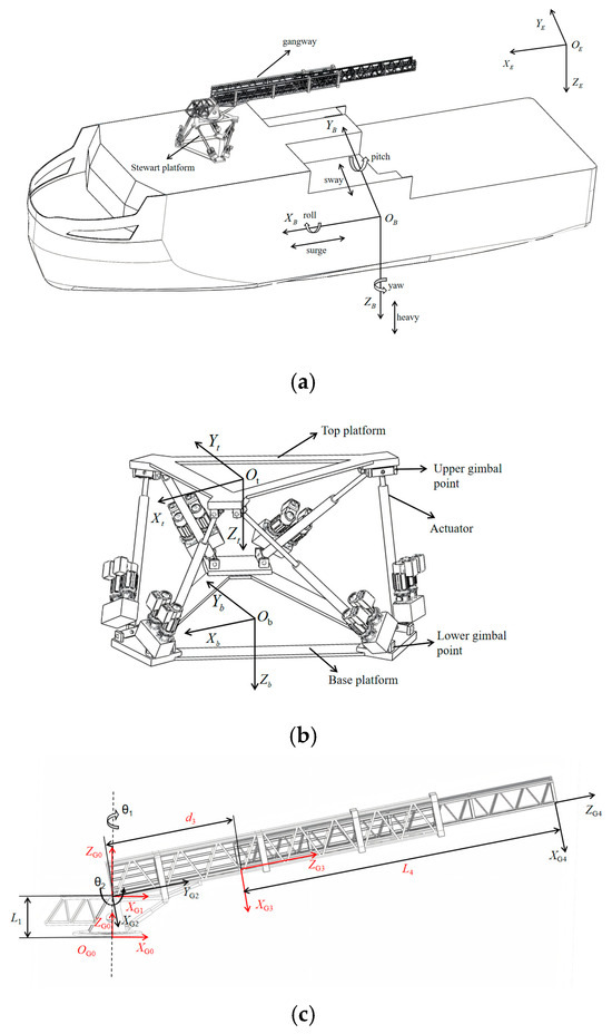
To provide a unified description of the kinematic relationships of the shipboard boarding system under wave-induced disturbances, a set of coordinate frames is established, as illustrated in Figure 1.
Figure 1.
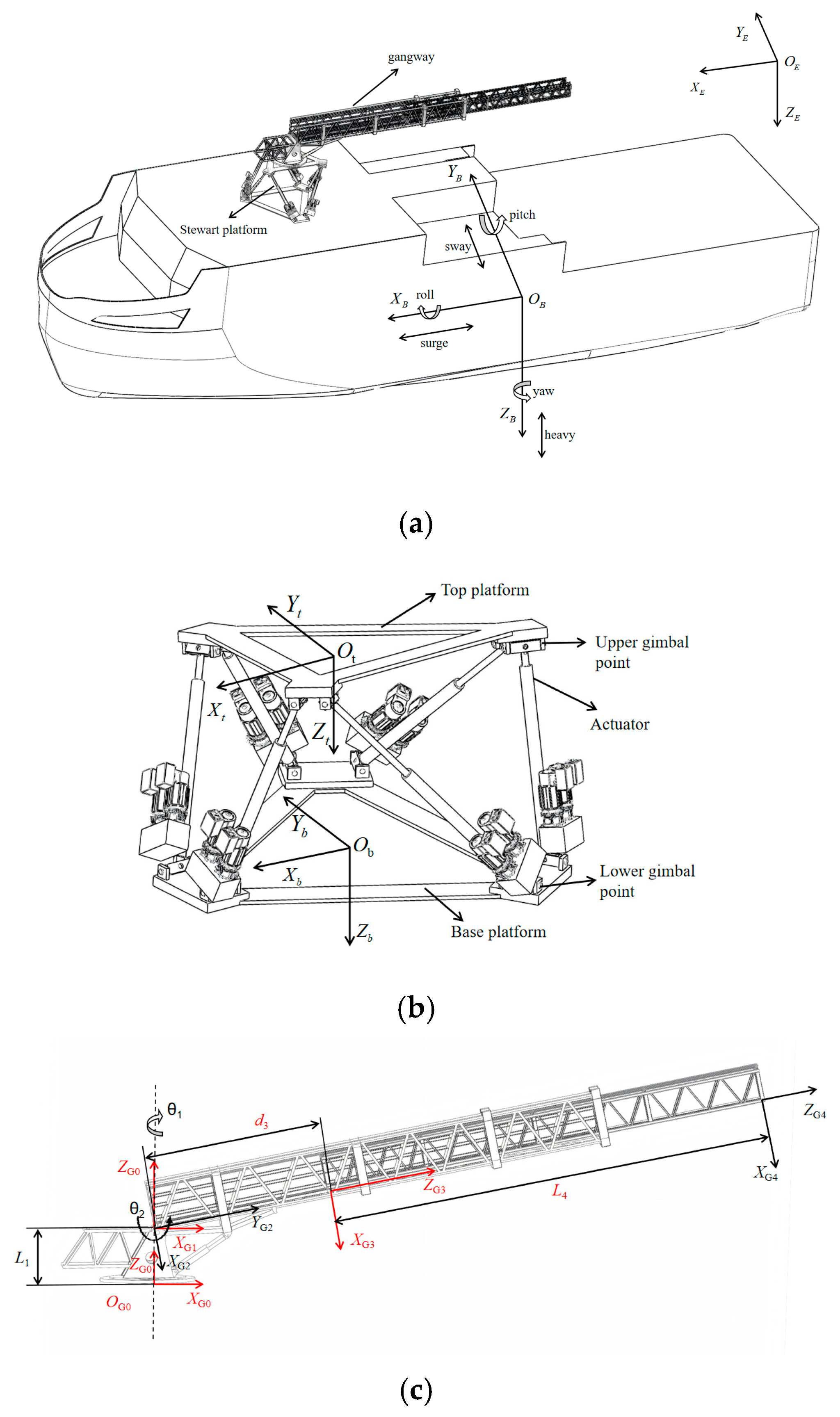
Coordinate system definition diagram: (a) Definition diagram of inertial coordinate system and ship fixed coordinate system; (b) Definition diagram of stewart platform coordinate system; (c) Definition diagram of the gangway coordinate system.
- (1)
- Inertial coordinate system , Take any point on the sea surface as the origin . The axis points due north, the axis points due east, and the axis points towards the Earth’s center. As shown in Figure 1a.
- (2)
- The ship fixed coordinate system , whose origin is located at the ship’s center of inertia, is used to establish the equation of motion. is the ship’s center of gravity, pointing vertically downwards, to the right, and in the direction of travel, , , are perpendicular to each other. As shown in Figure 1a.
- (3)
- The Stewart platform coordinate system, is the lower-platform coordinate system and the upper-platform coordinate system . The coordinate systems are fixed on the hull. The origins of the lower-platform coordinate system and the upper-platform coordinate system are located at the centers of the upper and lower platforms, respectively. As shown in Figure 1b.
- (4)
- The gangway coordinate system is set as follows: the center of the bottom of the base is the origin of the reference coordinate system , the center of the connection point between the base and the gangway pitch axis is the origin of and , A coordinate system is established at the center of the contact point between the gangway’s pitch axis and the top of the telescopic shaft, and a coordinate system is established at the end of the gangway’s telescopic shaft, as shown in Figure 1c.
2.2. Motion State Estimation Based on the Extended Kalman Filter
Ships are typical nonlinear systems with six degrees of freedom, and their six-degrees-of-freedom nonlinear dynamic model can be expressed as [17]:
In the formula, represents the position and rotation vectors in the ship’s inertial coordinate system, represents the linear and angular velocity vectors in the hull coordinate system, represents the mass and added mass matrix, including rigid body mass and fluid added mass , represents the Coriolis force and centripetal force matrix, represents the damping matrix, including linear and nonlinear damping terms, represents the static restoring force and torque, represents the external environmental disturbance, and represents the control force provided by the propeller.
Under complex sea conditions, ship state variables exhibit pronounced nonlinear characteristics. To enable accurate online estimation of ship motion states, an extended Kalman filter-based state estimator is designed as follows: . Where is the slowly varying external disturbance parameter of the sensor [18]. The discrete time state space model is:
In Equations (2) and (3), function is obtained by discretizing the ship dynamics model. is the observation function, which incorporates the following measurement models: a global positioning system model for position and heading measurements, an inertial measurement unit model for angular velocity and linear acceleration measurements, and a motion reference unit model for attitude-related motion estimation. and represent process noise and observation noise, respectively, both of which can be assumed to be uncorrelated Gaussian white noise. Based on the standard prediction and update iteration of the extended Kalman filter described above, the optimal state estimate of the ship can be obtained, providing input for subsequent disturbance separation and prediction.
2.3. Wave Disturbance Modeling and Short-Term Prediction
To generate the feedforward compensation signal, the high-frequency wave-induced disturbances acting on the ship must be modeled. In this study, the JONSWAP spectrum, which is widely adopted in offshore engineering applications, is employed to characterize the energy distribution of irregular waves. The spectral density function of the JONSWAP model is defined as [19]:
In the formula, is the angular frequency of the spectral peak, corresponding to the peak period , is the angular frequency, is the gravitational acceleration, is the spectral shape function, which is related to the peak frequency and the significant wave height, is the peak enhancement factor, and is the spectral width parameter.
The ship response to wave excitation is characterized by introducing the response amplitude operator, which establishes a frequency domain mapping from the wave spectrum to the ship motion response spectrum [20]:
To support time domain short-term prediction for feedforward compensation, the estimated ship motion obtained from the estimator in Section 2.2 is decomposed into low-frequency and high-frequency components using an exponential moving average low-pass filter [21]. With sampling time the low-frequency component is updated as:
where , is the filter time constant. The high-frequency component is defined by:
A Kalman filter-based lookahead predictor is then applied to to provide short-horizon prediction for feedforward compensation. The predictor state is defined as , where denotes the high-frequency velocity, and the constant velocity model is adopted:
In Equation (8), . Based on the filtered estimate , the steps lookahead prediction is obtained by:
The predicted velocity component , extracted from is used to construct the feedforward compensation reference of the upper-layer controller.
3. Coupled Kinematic Modeling of the Ship Boarding System
3.1. Forward Kinematic Analysis
The shipboard boarding system can be modeled as a multi-body system composed of a dynamically positioned ship, a Stewart platform, and a three-degrees-of-freedom gangway connected in series. To characterize the motion coupling among the ship, the Stewart platform, and the gangway, a coordinate transformation chain is introduced to establish a unified kinematic description framework [22]. Based on the coordinate system definitions provided in Section 2.1, the pose of the gangway end effector in the inertial reference frame can be expressed as follows:
where represents the time varying transformation from the inertial frame to the hull coordinate system determined by the ship’s six-degrees-of-freedom attitude; is the constant transformation describing the installation position and attitude of the Stewart lower platform on the hull; represents the six-degrees-of-freedom motion of the Stewart upper platform relative to the lower platform; represents the installation transformation of the gangway base relative to the Stewart upper platform; and represents the transformation from the gangway base to the gangway end system, determined by the gangway joint variable .
3.2. Velocity Mapping and Jacobian Formulation
To enable feedforward compensation and control allocation at the velocity level, a linear mapping between the generalized velocity vector and the terminal velocity screw is established. At this level, a generalized velocity vector is defined as follows:
where is the ship’s velocity within the ship system; is the velocity of the Stewart upper platform relative to the lower platform; and is the gangway joint velocity. The velocity spin of the gangway end effector in the inertial frame, denoted as , can be expressed as:
where , and denote the geometric Jacobian matrices associated with the ship, the Stewart platform, and the gangway, respectively, which quantify the contribution of each subsystem’s generalized velocity to the velocity of the gangway end effector. By applying the rigid body velocity transformation theorem and expressing the velocity transformations in screw coordinates, the local velocities of the ship center of gravity, the Stewart platform, and the gangway joints are consistently mapped into the coordinate frame attached to the gangway end effector. This mapping establishes a unified kinematic and mathematical basis for the subsequent control allocation.
4. Design of the Hierarchical Cooperative Control Architecture
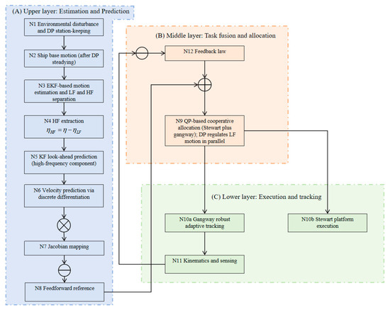
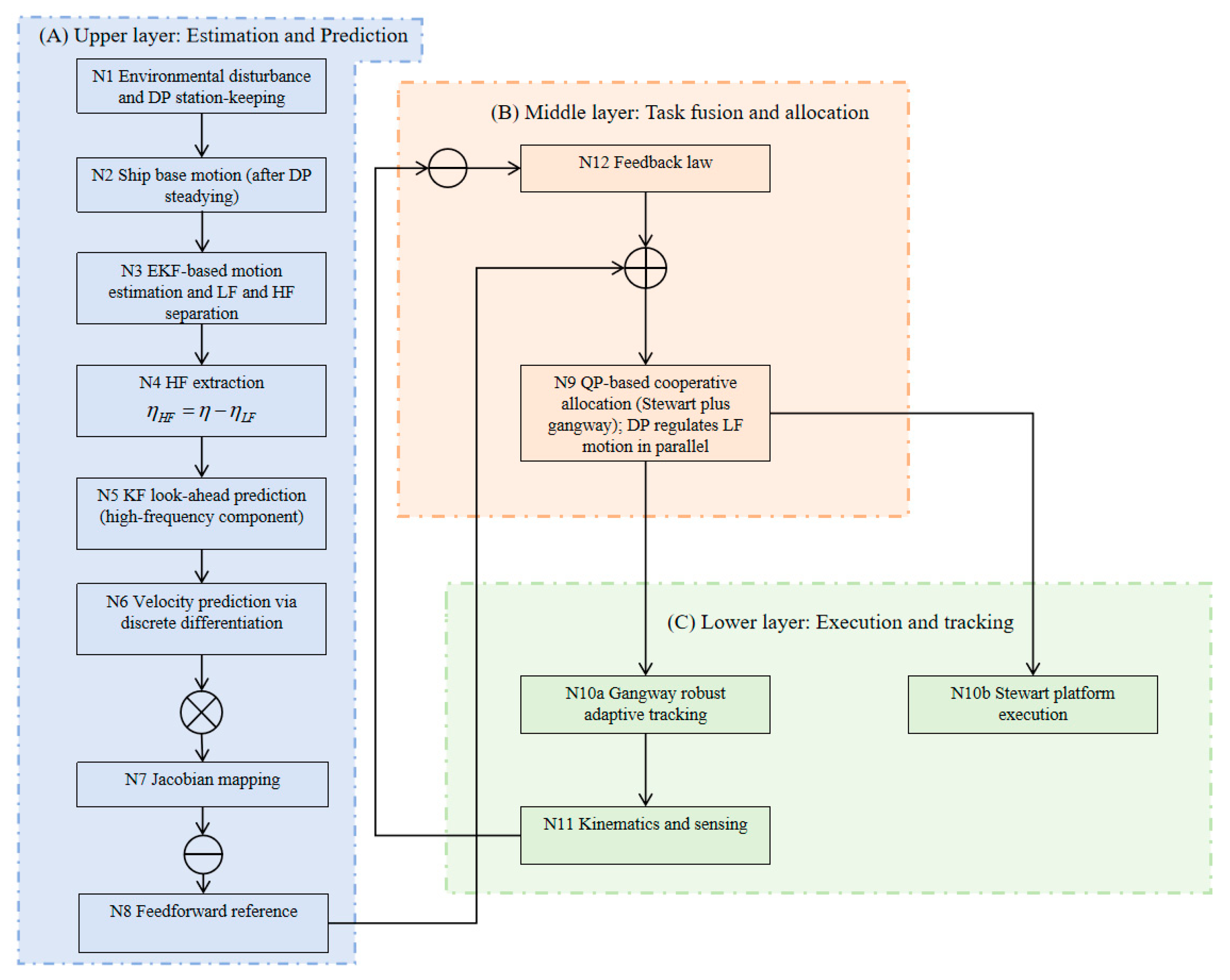
The proposed three-layer cooperative control architecture, as illustrated in Figure 2, decomposes the global motion compensation problem into hierarchically organized modules with clearly defined responsibilities and structured information flow.
Figure 2.
Algorithm principle diagram.
The upper layer performs online estimation of ship motion states and generates short-horizon predictions of the high-frequency disturbance component, while extracting low-frequency motion information that supports DP-based stabilization. Specifically, extended Kalman filtering is used for state estimation, an exponential moving average-based low-pass filter is adopted for low-frequency and high-frequency separation, and a Kalman filter lookahead predictor is employed to produce the predicted high-frequency motion sequence. Through the geometric mapping between the ship motion and the gangway end effector, the predicted disturbances are converted into an equivalent terminal disturbance velocity, which is used to construct the feedforward reference for downstream coordination [23].
The middle layer unifies the feedforward reference and the feedback correction derived from terminal task space errors, and determines the cooperative actuator commands via a quadratic programming-based allocation subject to actuator safety constraints, including stroke limits and singularity avoidance. In this layer, the ship DP system acts as a low-frequency stabilization unit within its effective bandwidth, while the Stewart platform and the gangway primarily compensate the residual high-frequency disturbances at the terminal level to mitigate cross-mechanism conflicts.
The lower layer focuses on physical execution and tracking. The Stewart platform is modeled as a controlled mechanical response unit that executes the allocated motion commands, while the gangway achieves accurate tracking of the assigned references through a robust adaptive feedback controller [24]. Measurement feedback of the end effector pose and velocity is provided to the middle layer through kinematics and sensing modules, thereby forming a complete closed-loop structure. The upper-layer prediction module remains decoupled from the error feedback loop, which preserves modularity and facilitates practical deployment.
To enhance reproducibility and provide implementation level details, Table 2 summarizes the key parameter settings of the proposed three-layer controller, including the upper-layer predictor, the middle-layer quadratic programming allocator, and the lower-layer robust tracking controller.
Table 2.
Key parameter settings of the three-layer controller.
4.1. Upper Layer: Feedforward Trajectory Generation Based on Wave Prediction
As the perception and prediction module of the hierarchical cooperative architecture, the upper layer aims to transform high-frequency ship motions into feedforward references for the boarding system. Rather than directly closing the motion control loop, this layer provides predictive disturbance information to coordinate compensation across subsystems [25].
The measured ship motion is decomposed into a low-frequency component and a high-frequency component using a first order low-pass filter with cutoff frequency . The residual is computed as , while is forwarded to support low-frequency stabilization within the effective bandwidth of the dynamic positioning system. The cutoff is selected between the effective bandwidth of dynamic positioning and the dominant wave frequency band, so that slowly varying motions are handled by dynamic positioning and wave-induced high-frequency motions are compensated by the local mechanisms, namely the Stewart platform and the gangway, thereby mitigating cross-layer competition.
Based on , a Kalman filter-based lookahead predictor generates the predicted high-frequency displacement sequence for the six degrees of freedom over the next steps. By applying a discrete difference operation to the predicted displacement sequence, the corresponding high-frequency velocity prediction sequence is obtained. Using the velocity mapping derived in Section 3.2, the contribution of ship motion velocities to the gangway end effector velocity is characterized by the ship geometric Jacobian, yielding the predicted disturbance velocity screw at the gangway end:
To counteract the predicted disturbance at the terminal, the ideal feedforward compensation command is defined as:
In the formula, represents the compensation velocity required at the end of the gangway to offset the residual wave frequency disturbance transmitted from the ship in the future. The predicted disturbance information obtained at the upper layer is utilized to construct feedforward compensation references at the gangway end and is subsequently dispatched to the local compensation mechanisms through the quadratic programming-based allocation module in the middle layer. Within this framework, the ship dynamic positioning system is confined to providing low-frequency stabilization and suppression of slowly varying disturbances within its effective control bandwidth, and does not directly participate in high-frequency terminal disturbance compensation.
To justify the selected cutoff, we perform a parameter sweep with and evaluate steady segment tracking metrics. The results are summarized in Table 3, indicating limited sensitivity within the tested range and supporting as a balanced choice.
Table 3.
Sensitivity of steady segment tracking performance to the cutoff angular frequency.
4.2. Middle Layer: Cooperative Control Allocation Based on Quadratic Programming
As the coordination center of the system, the middle controller receives both the feedforward command from the upper controller and the feedback error information from the lower controller. The primary objective of the middle layer is to optimally allocate the total terminal velocity to be compensated at the gangway end between the Stewart platform and the three-degrees-of-freedom gangway, while explicitly satisfying actuator safety constraints. Through this allocation process, high-frequency disturbances acting on the gangway end are actively attenuated, and unnecessary or counterproductive mechanical motions of the actuators are avoided. Let the desired pose of the gangway end be , and the actual pose of the gangway end be . Then, the gangway end pose error vector can be obtained through logarithmic mapping. Based on this error vector, proportional control can be used to generate feedback speed commands:
In the formula, represents the feedback gain, which can be weighted separately for attitude and position. The total expected compensated velocity at the end of the gangway is:
In the formula, is the adaptive weight, which tends to 1 when the covariance of the prediction error is small.
The decision variable is defined as , where is the velocity screw of the Stewart platform, is the speed of the gangway joint, and the total Jacobian matrix of the boarding system is . It should be emphasized that the middle-layer cooperative allocation does not assign identical roles to all actuation subsystems. The ship dynamic positioning system operates as a low-frequency stabilization and slow drift regulation unit, and it is incorporated into the cooperative framework only within its effective control bandwidth. Its primary function is to shape the motion characteristics of the hull base and to mitigate potential conflicts among heterogeneous actuators that may otherwise operate over overlapping frequency ranges. In contrast, the Stewart platform and the three-degrees-of-freedom gangway directly compensate the high-frequency residual disturbances at the terminal level. To achieve accurate terminal tracking, energy efficient actuation, and smooth motion execution, the cooperative allocation is formulated as a constrained quadratic programming problem, as described in [26]:
In the formula, is the dynamic task weight matrix, whose value is adaptively adjusted according to the current error state to realize priority management between different tasks, and is the control increment penalty weight to ensure smoothness. The above optimization problem is subject to the following linearization constraints [27]:
where is the sensitivity vector that linearizes the minimum singular value to the joint displacement onto the single step velocity; is the safety threshold, i.e., the minimum singular value of the next step should not be lower than this value to ensure sufficient control margin; is the slack variable used to handle soft constraints. The interior point method is used to solve the above quadratic programming problem to obtain the optimal control command and issue it to the corresponding actuator.
To assess the real time feasibility of the online quadratic programming allocator, we profile the per step computation time of the online stack over the steady segment, excluding the first 50 steps. Table 4 reports the mean, the 95th percentile, and the maximum computation time for the prediction module, the middle-layer quadratic programming allocator including problem formulation and solver time, and the overall main loop. It also reports the solver success ratio indicated by , the real time success ratio defined by , and the fallback rate. The results confirm that the proposed online allocator satisfies the sampling time requirement under the tested settings.
Table 4.
Real time feasibility statistics of the middle-layer quadratic programming allocator.
4.3. Lower Layer: Robust Adaptive Tracking Control
Within the hierarchical cooperative control architecture, the middle-layer planning module allocates compensation tasks among the actuation subsystems of the boarding system and generates executable gangway joint velocity references that satisfy kinematic and safety constraints. At the lower layer, the control objective no longer involves cooperative decision making among multiple actuators. Instead, it focuses on stable and accurate execution of the allocated commands by the gangway subsystem in the presence of dynamic uncertainties and external disturbances. At this layer, the ship dynamic positioning system realizes hull stabilization commands through thrust allocation and propeller dynamics. However, it does not directly regulate the gangway end effector tracking error in closed loop, which preserves a clear separation between low-frequency hull stabilization and high-frequency terminal compensation. As a result, fine motion compensation is completed by the boarding system without interference from ship level control actions. Accordingly, this section focuses on the design of a local robust adaptive tracking controller for the gangway dynamics. The proposed controller compensates modeling uncertainties and external disturbances, thereby enhancing engineering feasibility and closed-loop stability of the overall hierarchical cooperative control framework [28].
The dynamics of the gangway system can be expressed as:
In the formula, is the joint variable of the gangway, is the inertial matrix of kinetic energy, is the Coriolis and centrifugal term, is the gravity term, is the control input of the gangway actuator, and is a lumped uncertainty term, which can be decomposed into a linearly parameterized part and a bounded residual .
The intermediate controller provides the total expected gangway end compensation velocity and the joint velocity allocated through quadratic programming. Integrating yields the gangway joint reference displacement . The goal of the lower controller is to ensure that the actual gangway joint displacement stably tracks this reference displacement. The tracking error is defined as:
To balance transient response and steady-state accuracy, the following sliding mode variables are introduced:
In the formula, is a positive definite diagonal matrix used to adjust the error convergence rate. This sliding mode variable combines the displacement error with its derivative, enabling the system to maintain good dynamic performance even when disturbances are present. The control input consists of the superposition of equivalent compensation terms and robust compensation terms. A virtual reference velocity is defined, and the adaptive robust control law is designed as follows:
In the formula, is the adaptive feedforward term, is the robust feedback term, and are represented as follows:
In the formula, represents the dynamic parameters estimated online (mass, centroid, inertia, etc.); is a positive definite gain matrix; is used to compensate for parameter uncertainties, and its design should satisfy: , where . The parameter adaptive law is designed as follows [29]:
where is a positive definite adaptive gain matrix. Furthermore, the gangway system described by Equation (19), under the action of the adaptive robust control law and the parameter adaptive law, takes the Lyapunov function:
where . Using the standard Euler Lagrange property that is skew symmetric, the time derivative of satisfies:
Substituting (19) and (22)–(24) together with yields:
With the adaptive law (25), the cross-term is canceled, and hence:
In implementation, is chosen as with boundary layer thickness . Assuming and selecting lead to , which implies that is uniformly ultimately bounded and thus the tracking error converges to a small neighborhood.
5. Robustness and Stability Analysis
5.1. Mixed Sensitivity–Based Robustness Analysis
Within the feedforward and feedback cooperative control framework, the ship dynamic positioning system serves as the low-frequency stabilization and slow drift suppression layer. The robustness of this layer is a fundamental prerequisite for reliable operation of the overall architecture, because it directly determines the stability of the ship motion baseline on which the subsequent compensation layers rely. The control problem of the ship dynamic positioning system is placed under the standard hybrid sensitivity framework , which can optimize disturbance suppression and noise response characteristics while ensuring robust stability. Based on the nominal mapping from propeller resultant forces and moments to ship position and attitude responses, a generalized plant is constructed for robustness analysis. In this formulation, external environmental disturbances, measurement noise, and control inputs are treated as exogenous system inputs, while ship position and attitude tracking errors, together with control efforts, are incorporated into the performance and measurement outputs, respectively. This generalized representation provides a unified framework for evaluating disturbance rejection, noise attenuation, and control robustness under mixed sensitivity design criteria. On this basis, sensitivity weights and complementary sensitivity weights are introduced, and a stabilization controller is designed so that the entire closed-loop system satisfies [30,31]:
In the formula, is the sensitivity function, used to describe the transmission characteristics from disturbance to error, mainly affecting low-frequency steady-state error; is the complementary sensitivity function, used to describe the high-frequency transmission characteristics from disturbance to output. In the low-frequency band, a larger sensitivity weight is set to reduce the amplitude of , thereby significantly reducing the stability deviation of position and heading, and reducing the impact of ship slow drift disturbances on the wave compensation boarding system; in the high-frequency band, an appropriate complementary sensitivity weight is set to keep relatively small in the high-frequency range, thereby avoiding the dynamic positioning system from excessively following high-frequency disturbances and measurement noise.
The solution for controller can be obtained by solving two algebraic Riccati equations. Let the state space realization of the generalized controlled object be . Given , find a transfer function for the closed-loop system from external input to performance output. Find two stable solutions and such that the following ARE (Algebraic Riccati Equation) holds:
The solution to the above equation satisfies coupling feasibility, i.e., , where is the spectral radius. This ensures the stability of the closed-loop system and achieves the mixing sensitivity performance index required by inequality (30).
5.2. Input to State Stability Analysis
To ensure reliable operation of the proposed feedforward and feedback cooperative control system under complex sea conditions, this subsection examines closed-loop stability from the perspective of input to state stability. The input to state stability framework provides a systematic means to quantify how external environmental disturbances, including waves, wind, and currents, as well as internal uncertainties arising from modeling inaccuracies and prediction errors, affect tracking performance. Within the proposed cooperative control architecture, the wave-compensated boarding system is modeled as a nonlinear closed-loop system, in which environmental disturbances and prediction errors are treated as exogenous inputs. This formulation enables a unified analysis of how bounded disturbances and uncertainties propagate through the hierarchical control structure and affect the boundedness and convergence properties of the system states. Given an augmented state and an external input , if there exist -like functions and -like functions such that any initial value and any bounded input satisfy [32]:
The system is then input to the stable state. In the proposed framework, the feedforward signal is generated by the upper-layer short-horizon predictor, and the associated prediction mismatch is treated as an exogenous input in the input to state stability sense. In this study, the predictor is implemented using exponential moving average-based low-pass filtering for low-frequency and high-frequency separation together with a Kalman filter-based lookahead estimator. The resulting prediction error is denoted by and is assumed to satisfy the bound .
In this framework, the prediction error and environmental disturbance in the feedforward loop are considered as external input , and the gangway end effector error and its associated internal state are considered as augmented state . Within the proposed feedforward and feedback cooperative control framework, the feedforward module maps bounded external disturbances and measurement noise into bounded feedforward compensation signals. The control allocation module further converts the desired end effector velocity into actuator command inputs with bounded gains under prescribed physical and safety constraints. Meanwhile, the feedback control loop guarantees that both joint level tracking errors and end effector errors remain bounded for bounded reference commands. When the overall gain of the cascaded interconnection formed by the feedforward mapping, control allocation, and feedback regulation is properly bounded and satisfies the small gain condition, the input to state stability cascade theorem ensures that the entire feedforward and feedback cooperative control system preserves input to state stability in the presence of bounded external disturbances and prediction errors.
In the formula, represents the attitude error at the end of the gangway; represents the upper bound of the environmental disturbance; represents the upper bound of the motion prediction error; and represent the corresponding input and state stability gain functions. In this stability analysis, the stabilization and adjustment effect of the ship’s dynamic positioning system is reflected in the constraint on the amplitude and trend of low-frequency external disturbances. Its dynamic state is not directly incorporated into the augmented state vector of the boarding system, but rather indirectly affects the stability analysis of the execution layer as part of the external input structure.
6. Simulation Verification and Result Analysis
6.1. Simulation Environment Setup
To validate the effectiveness of the proposed hierarchical cooperative control architecture based on dynamic positioning feedforward, a comprehensive numerical simulation platform was developed in the MATLAB environment. The key mechanism parameters adopted in the simulation are summarized in Table 5, Table 6, Table 7 and Table 8. The simulation framework was constructed in strict accordance with the physical configuration and control logic of a practical shipboard boarding system, and consists of three coupled subsystems, namely the ship motion model, the Stewart platform compensation mechanism, and the gangway actuator system. Information exchange and cooperative control among these subsystems are realized through the proposed hierarchical control architecture. The kinematic coupling relationship among the ship, Stewart platform, and gangway is described by Equation (10), while the mapping between the gangway end effector velocity and the generalized velocities of the individual subsystems is defined by Equations (11) and (12). These formulations ensure that the terminal response under different control strategies can be evaluated in a consistent and unified manner within the simulation framework.
Table 5.
Parameters of Ship Dynamics Model.
Table 6.
DP Thruster Parameter Table.
Table 7.
Stewart Platform Parameter Table.
Table 8.
Gangway Parameter Table.
The main simulation program is executed in the discrete time domain with a fixed sampling interval of 0.05 s and a total simulation duration of 600 s. Within each sampling period, the upper-layer disturbance prediction, middle-layer cooperative allocation, and lower-layer tracking control are executed sequentially, thereby faithfully reproducing the information flow and temporal coordination inherent to the proposed hierarchical control architecture.
The environmental conditions were simulated using random waves generated by the JONSWAP wave spectrum. The sea state was set as follows: significant wave height , peak period , and peak enhancement factor . To approximate engineering reality, the role of the ship’s dynamic positioning system was equivalent to the effective suppression of low-frequency motion. The residual hull motion after DP compensation was retained in the simulation as a disturbance input that the boarding system needed to handle. Control parameters and system physical parameters were uniformly initialized before the simulation began, including controller gain, quadratic programming weight matrix, actuator limits, etc. All modules read the required information from a unified parameter configuration file, thereby ensuring consistency in parameter management and facilitating subsequent sensitivity analysis and comparative experiments.
6.2. Results Analysis
The simulation results are evaluated from four complementary perspectives, including the execution performance at the gangway end, the behavior of the cooperative allocation mechanism, the operational characteristics of the lower-level controller, and the system response to environmental disturbances, thereby providing a comprehensive assessment of the overall performance of the proposed hierarchical cooperative control architecture.
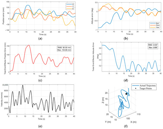
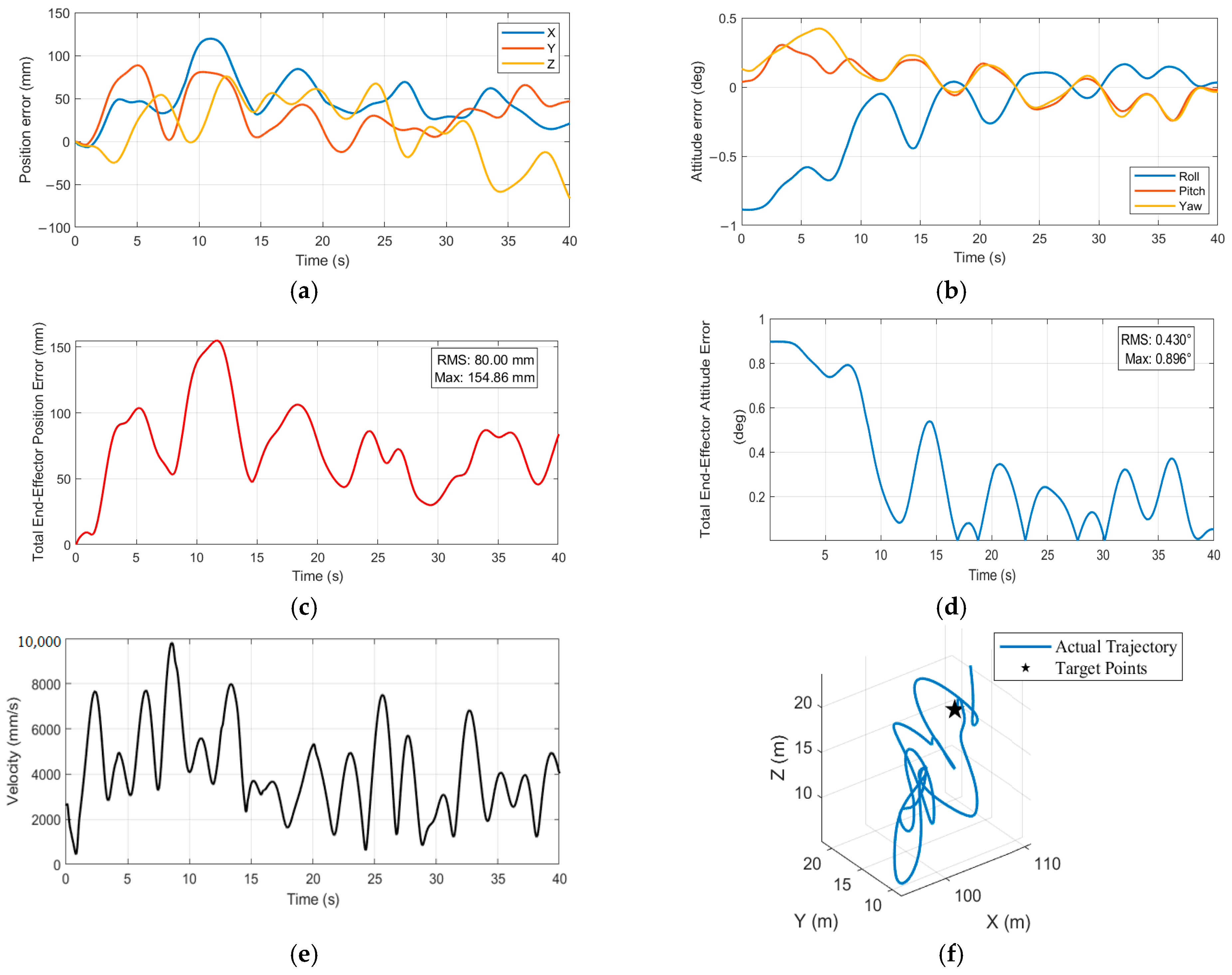
Figure 3a–f present the pose tracking errors, comprehensive error indices, motion smoothness metrics, and three dimensional trajectory performance of the gangway end effector in the inertial coordinate system. These results are used to evaluate the final closed-loop performance of the proposed hierarchical cooperative control architecture under coupled environmental disturbance conditions.
Figure 3.
Gangway end effector performance evaluation: (a) Gangway End Effector Position Error; (b) Gangway End Effector Orientation Error; (c) Total Gangway End Effector Positioning Error; (d) Total Gangway End Effector Orientation Error; (e) Gangway End Effector Linear Velocity (Smoothness Evaluation); (f) Gangway End Effector Motion Trajectory.
Figure 3a illustrates the time histories of the gangway end effector position errors along the X-, Y-, and Z-directions. It can be observed that the position errors exhibit a superposition of low-frequency variations and high-frequency oscillatory components. This error characteristic indicates that the terminal position deviations are mainly influenced by the residual low-frequency ship motion components remaining after dynamic positioning stabilization, together with the kinematic constraints of the boarding system and the redistribution effects introduced by the middle-layer quadratic programming-based cooperative allocation strategy, rather than being dominated by measurement noise or purely stochastic disturbances. In terms of error magnitude, the X-direction position error reaches its maximum peak during the simulation interval of approximately 10–15 s, with an amplitude on the order of 120 mm. The Y-direction error exhibits a relatively smaller peak magnitude, remaining within the range of 80–90 mm. In contrast, the Z-direction position error shows a more pronounced negative deviation in the later stage of the simulation, particularly after approximately 20 s, with peak values ranging from −70 mm to −90 mm. These observations indicate that vertical motion disturbances exert a more significant influence on the terminal position accuracy of the gangway under the considered sea conditions, highlighting the importance of effective vertical disturbance compensation within the overall control architecture.
Figure 3b presents the attitude tracking errors of the gangway end effector in the roll, pitch, and yaw degrees of freedom. Compared with the position errors, the attitude errors exhibit significantly smaller amplitudes, and after approximately 15–20 s of simulation time, the error trajectories converge to small oscillations around zero. This behavior indicates favorable steady-state performance and robustness of the closed-loop attitude regulation. Specifically, the roll angle error shows a noticeable negative deviation during the initial transient phase (0–10 s), with a peak magnitude close to −0.9°, followed by gradual convergence and stabilization within a narrow oscillation band of approximately ±0.2°. The pitch and yaw angle errors remain comparatively smaller throughout the simulation, with peak values in the range of 0.3–0.4°, and exhibit clear convergence trends in the later stages, with oscillation amplitudes effectively suppressed. These results demonstrate that the proposed hierarchical cooperative control architecture is highly effective in mitigating the influence of residual high-frequency disturbances on the terminal attitude of the gangway. The rapid convergence and bounded oscillatory behavior of the attitude errors reflect the strong disturbance rejection capability of the feedback control loop in the presence of modeling uncertainties and external excitations. Furthermore, the coordinated attenuation of attitude errors across multiple rotational degrees of freedom verifies the rationality and effectiveness of the middle-layer quadratic programming-based allocation strategy in distributing attitude compensation tasks among the available actuation mechanisms.
Figure 3c,d present the total position error and total attitude error of the gangway end effector, respectively. The total position error is obtained by synthesizing the Euclidean norm of the position deviations along the X-, Y-, and Z-directions, while the total attitude error is computed as the Euclidean norm of the roll, pitch, and yaw attitude deviations. As shown in Figure 3c, the total position error rapidly converges to within 50 mm during the initial simulation phase (0–5 s), and subsequently exhibits quasi periodic fluctuations induced by wave disturbances. Statistical analysis indicates that the overall root mean square error is 80 mm, with a maximum error of 154.86 mm. These results demonstrate that the proposed hierarchical cooperative control architecture achieves an engineering acceptable level of position compensation, remaining well below the commonly adopted safety threshold of 200 mm for offshore boarding operations. Notably, during the steady-state phase of the simulation (t > 20 s), the position error consistently remains below 100 mm, further confirming the capability of the system to suppress long-term disturbance effects. Figure 3d shows the evolution of the total attitude error. The attitude error converges rapidly to within 0.5° in the initial simulation stage (0–5 s) and subsequently exhibits periodic oscillations correlated with wave excitation, with prominent peaks occurring at the dominant wave disturbance instants (e.g., t ≈ 10 s and t ≈ 20 s). The overall RMS value of the attitude error is 0.430°, and the maximum observed error is 0.986°. Throughout the entire simulation interval, the attitude error remains bounded within 1°, which is significantly lower than the typical engineering safety threshold of 2° for maritime boarding operations. These results indicate that the proposed control framework provides favorable steady-state performance and robustness in attitude compensation under persistent wave disturbances.
Figure 3e shows the scalar linear velocity of the gangway end effector. Several peaks occur in the early phase (t ≈ 5 s and t ≈ 15 s), reaching approximately 10,000 mm/s, while the subsequent oscillations are mainly bounded within 2000–8000 mm/s. The transient peaks arise from the limited time available for compensating wave-induced deviations when predictive feedforward and feedback correction are jointly applied. The bounded and continuous velocity response indicates that the cooperative allocation and tracking controller respect the actuator dynamic limits.
Figure 3f illustrates the three dimensional spatial trajectory of the gangway end effector, where tracking accuracy is evaluated based on the deviation from the predefined target point. The resulting trajectory reveals a bounded reciprocating motion around the target location, forming a compact oscillatory pattern rather than exhibiting unbounded drift or divergence. The limited spatial spread of the trajectory indicates that the proposed hierarchical cooperative control architecture effectively maintains the end effector in the vicinity of the desired boarding target under continuous wave disturbances. This behavior confirms the long-term stability and positioning reliability of the system during simulated boarding operations.
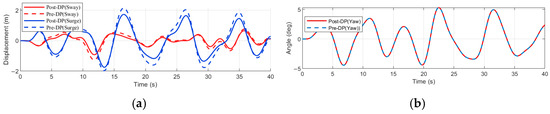
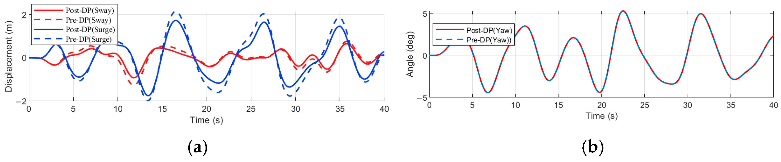
Figure 4a,b compares the low-frequency motion responses of the ship hull in the surge, sway, and yaw degrees of freedom before and after the activation of the dynamic positioning system. It can be observed that the overall amplitudes of the motion responses under the two conditions remain highly comparable, indicating that, under the considered sea state and controller parameter settings, the dynamic positioning system does not continuously suppress low-frequency drift through aggressive force compensation. Nevertheless, noticeable differences can be identified in terms of phase evolution and peak distribution across multiple time intervals after the activation of the dynamic positioning system. Compared with the uncontrolled case, the responses with dynamic positioning exhibit evident phase shifts and temporal redistribution of extreme values, reflecting a modification of the underlying motion dynamics. These observations suggest that the dynamic positioning system primarily contributes by shaping the low-frequency motion characteristics of the ship, including the regulation of slow drift trends and phase alignment, rather than by directly eliminating low-frequency displacement components.
Figure 4.
Low-frequency planar ship motion response under DP steadying: (a) Low-frequency surge and sway displacement; (b) Low-frequency yaw angle response.
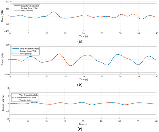
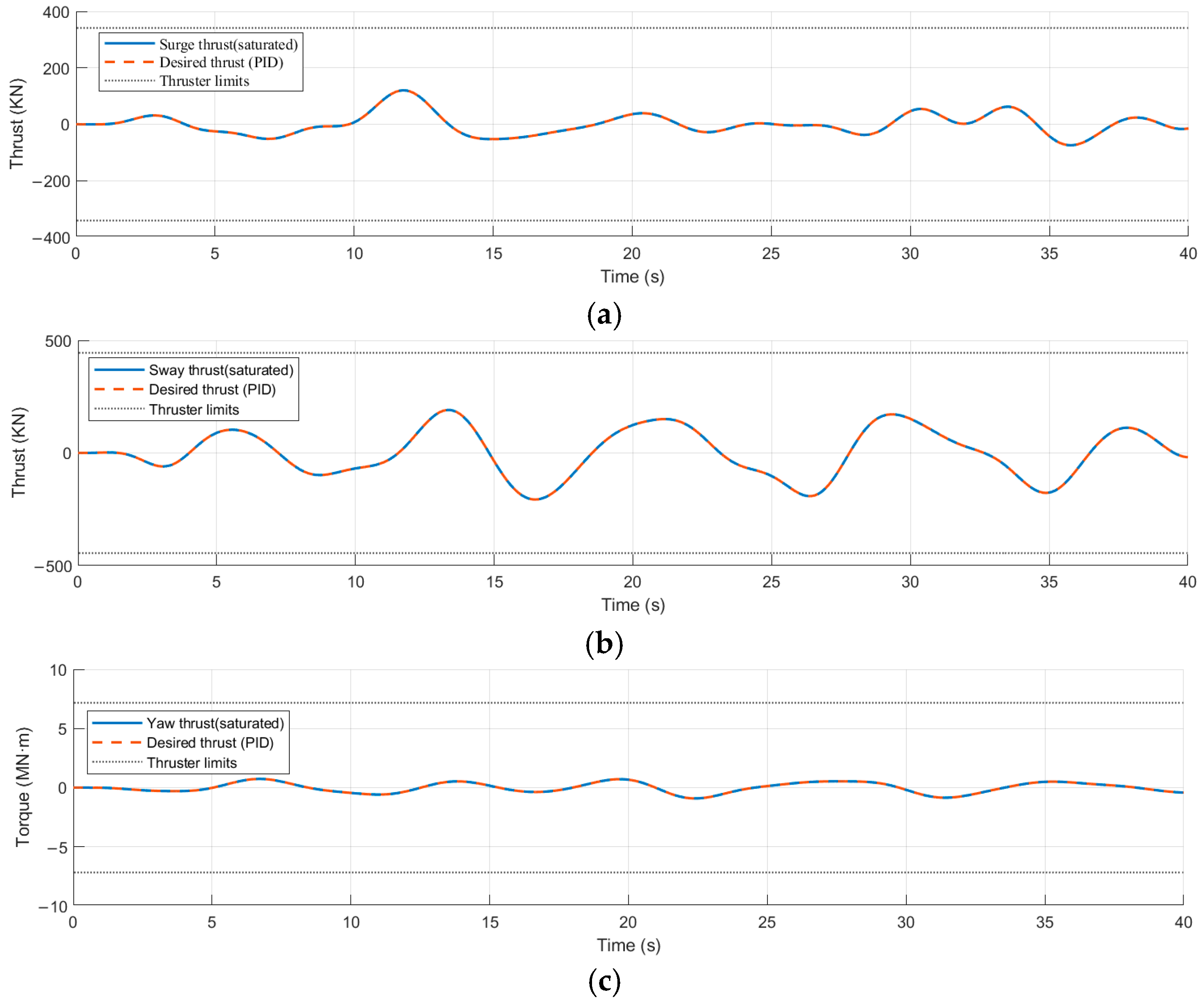
Figure 5a–c illustrates the control output responses of the dynamic positioning system in the horizontal degrees of freedom. Throughout the entire simulation, the control outputs remain at relatively low levels and are well below the physical saturation limits of the thrusters. This behavior indicates that, within the proposed hierarchical cooperative control framework, the dynamic positioning system intervenes only when a pronounced slow drift tendency is detected, rather than continuously enforcing strong corrective actions. Such a response pattern effectively avoids competition in control effort between the dynamic positioning system and the Stewart platform and gangway compensation mechanisms operating in overlapping frequency ranges. From a system level perspective, these results indirectly verify the rationality of the proposed frequency band decoupling and task allocation strategy. Specifically, low-frequency horizontal drift is addressed by the dynamic positioning system through macroscopic stabilization, while high-frequency disturbances and vertical motion components are finely compensated by the boarding system.
Figure 5.
Control effort of the dynamic positioning system: (a) Surge direction control force output; (b) Sway direction control force output; (c) Yaw direction control moment output.
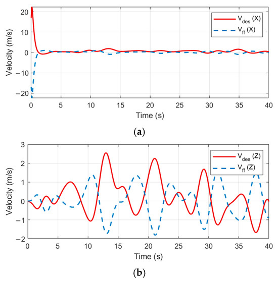
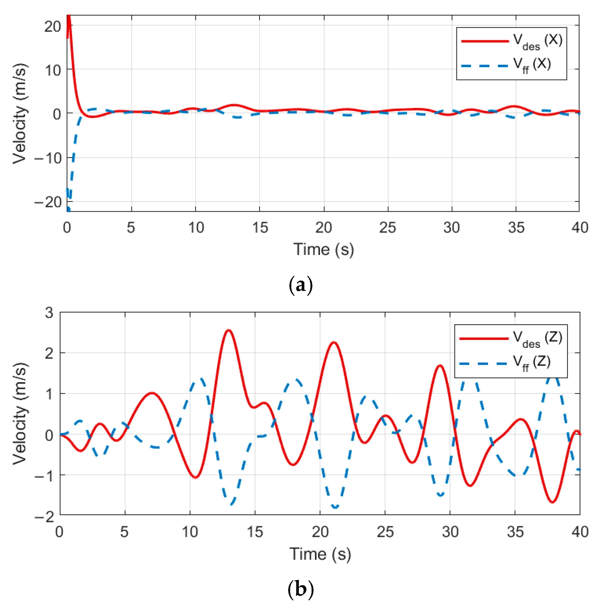
Figure 6a,b present the feedforward compensation velocity and the desired gangway end velocity obtained after feedforward and feedback coordination in the X- and Z-directions, respectively, of the wave-compensated boarding system. In the X-direction, the feedforward module generates pronounced compensatory velocity components in response to high-frequency disturbances, with a noticeable spike appearing at the initial stage of the simulation. This behavior reflects the anticipatory nature of the feedforward action, which aims to counteract the imminent disturbance based on short-term prediction. Subsequently, the feedforward and feedback coordination module integrates the feedforward signal with the terminal tracking error, producing a desired gangway end velocity that attenuates excessive transient peaks while preserving the dominant disturbance trend. This coordinated response indicates that the proposed control strategy effectively balances trajectory tracking accuracy with the suppression of unnecessary actuator excitation. In the Z-direction, observable differences in both amplitude and phase are present between the feedforward compensation velocity and the coordinated desired gangway end velocity. After fusing the feedforward prediction and the real time end effector error information, the coordinated velocity command exhibits an amplitude that more closely matches the actual compensation demand. This result demonstrates that, under the dominance of strong high-frequency vertical disturbances, the feedforward and feedback coordination mechanism can adaptively adjust the compensation target based on real time error feedback while still leveraging the predictive capability of the feedforward module.
Figure 6.
Comparison between feedforward compensation velocity and desired end effector velocity under cooperative control: (a) Desired vs. feedforward velocity in X-direction; (b) Desired vs. feedforward velocity in Z-direction.
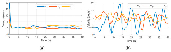
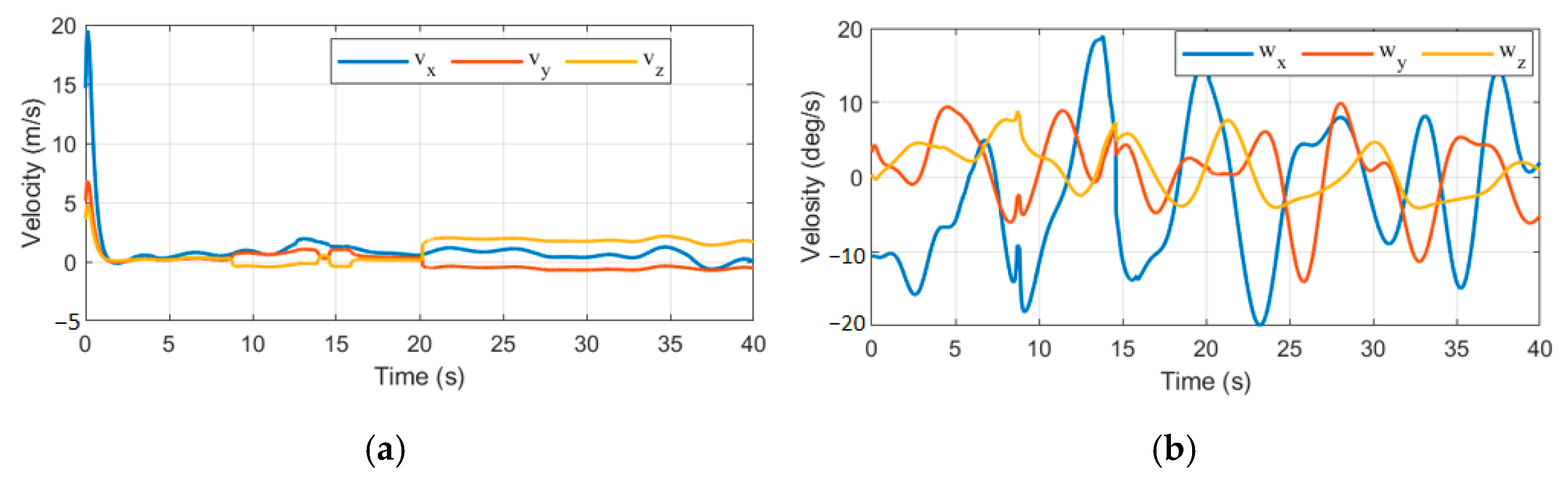
Figure 7a,b illustrates the translational and rotational velocity commands generated by the feedforward and feedback cooperation module, i.e., the quadratic programming optimizer, for the Stewart platform. Figure (a) shows three translational degrees of freedom, and Figure (b) shows three rotational degrees of freedom. As can be seen from the figures, the commands for each channel exhibit significant periodic variations near the dominant wave frequency, but the overall amplitude is limited and the changes are continuous, without high-frequency spikes or prolonged saturation. This indicates that the optimizer effectively considers actuator constraints and motion smoothness while meeting end effector compensation requirements, providing an achievable reference trajectory for subsequent joint level tracking control.
Figure 7.
Velocity command allocation to the Stewart platform by the cooperative module: (a) translational velocities of the Stewart platform; (b) angular velocities of the Stewart platform.
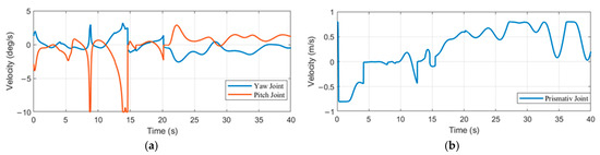
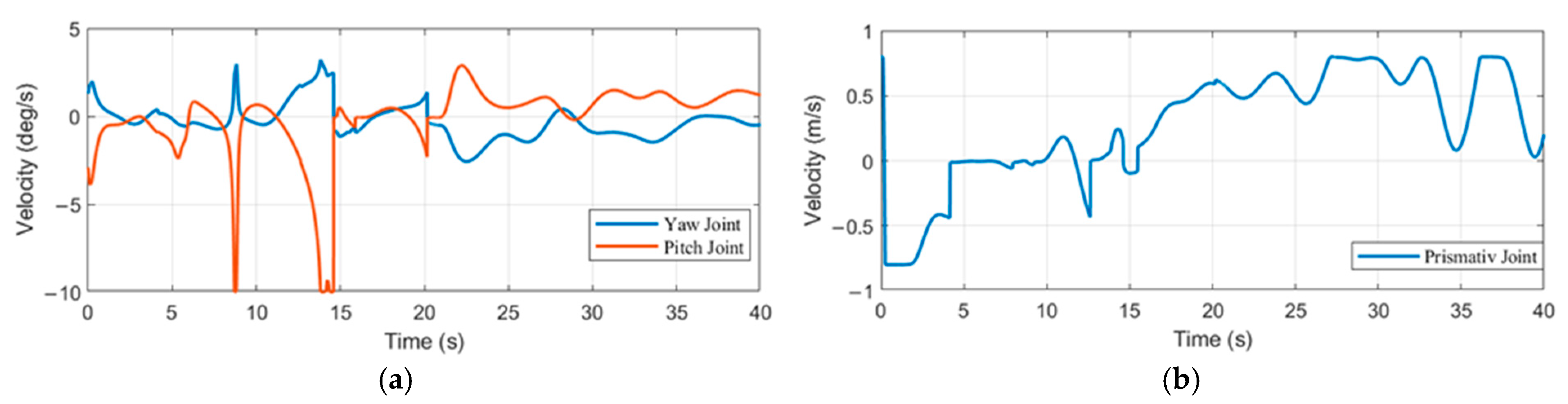
Figure 8a,b illustrates the velocity commands assigned by the feedforward and feedback cooperation module to the rotational, pitching, and telescopic joints of the gangway. As shown in the figures, each joint exhibits periodic adjustments near the dominant wave frequency. A brief increase appears during approximately 10 s to 15 s, which is attributed to external disturbances and the redistribution of compensation tasks, and no sustained saturation is observed. Thereafter, the joint velocities decrease rapidly and remain close to zero with small oscillations. This behavior indicates that the cooperative optimization limits both the motion range and the rate of change of the gangway joints while still satisfying the end compensation requirements. Such a property helps avoid excessive actuation and reduces the risk of mechanism fatigue.
Figure 8.
Cooperative commands for gangway joint velocities: (a) Yaw and pitch joint velocities; (b) Prismatic joint velocity.
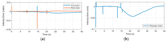
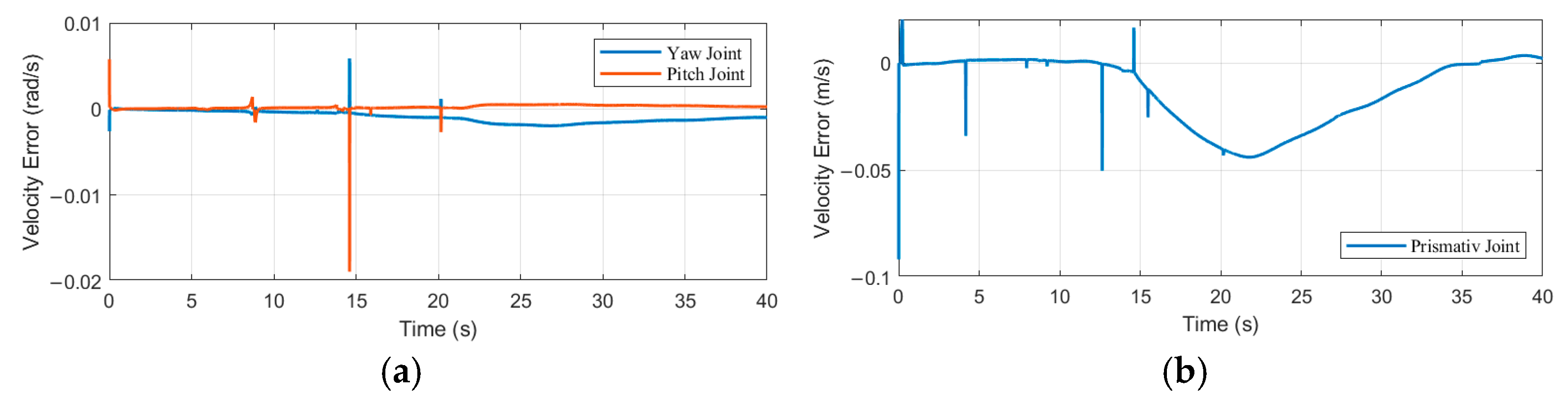
Figure 9 shows the time varying sliding surface of the adaptive sliding mode controller in the feedback module. The sliding surface directly reflects the magnitude of the velocity tracking error and can therefore serve as a key indicator of the controller operating condition and tracking performance. In Figure (a), the gyratory and pitch joints are mostly constrained within an extremely narrow velocity band of ±0.01 rad/s, with only a short-term spike appearing when the reference command changes abruptly at approximately 10–15 s, followed by a rapid return to near zero, indicating that the angular velocity tracking error is very small and converges quickly. In Figure (b), the deviation amplitude of the sliding surface of the telescoping joint is within approximately 0.1 m/s, with a smooth overall change and no continuous oscillations or chattering. Combining the two figures, it can be determined that the sliding mode controller of the feedback module maintains good sliding mode proximity throughout the simulation process, effectively tracking the velocity commands issued by the coordination module, and providing stable and reliable execution support for the upper-level feedforward and feedback coordination allocation.
Figure 9.
Sliding surface response of the feedback module (velocity tracking error): (a) Yaw and pitch joint velocities; (b) Prismatic joint velocity.
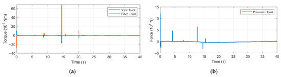
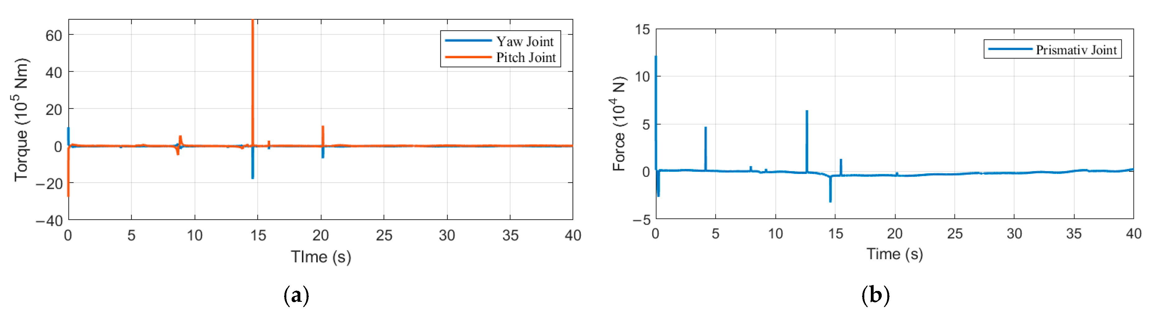
Figure 10a illustrates the control torques generated by the lower-level robust adaptive sliding mode controller at the yaw and pitch joints. During the initial transient phase of the simulation (0–5 s), pronounced torque peaks are observed, with the yaw joint torque reaching approximately 60 N·m and the pitch joint torque approximately −20 N·m. These transient responses correspond to the rapid error correction required at the onset of control execution. Subsequently, the control torques decay rapidly toward zero and remain within a small bounded range, with fluctuation amplitudes below 5 N·m, without exhibiting sustained oscillations or actuator saturation. Figure 10b presents the control force applied to the prismatic joint by the same controller. A similar transient behavior is observed, characterized by an initial force peak of approximately 10 N, followed by rapid convergence. After t > 10 s, the control force stabilizes within a narrow band of ±2 N, with negligible residual fluctuations. The combined results of Figure 10a,b demonstrate that the proposed lower-level controller achieves fast convergence and uniformly bounded control inputs throughout the simulation. Such behavior ensures accurate joint level tracking performance while effectively mitigating the risks of actuator overload and excessive energy consumption. These characteristics provide strong evidence of the practicality, safety, and reliability of the lower-level control strategy within the overall hierarchical cooperative control framework.
Figure 10.
Control force and torque diagrams for yaw–pitch–prismatic joints: (a) Control torques for the yaw and pitch joints; (b) Control force for the prismatic joint.
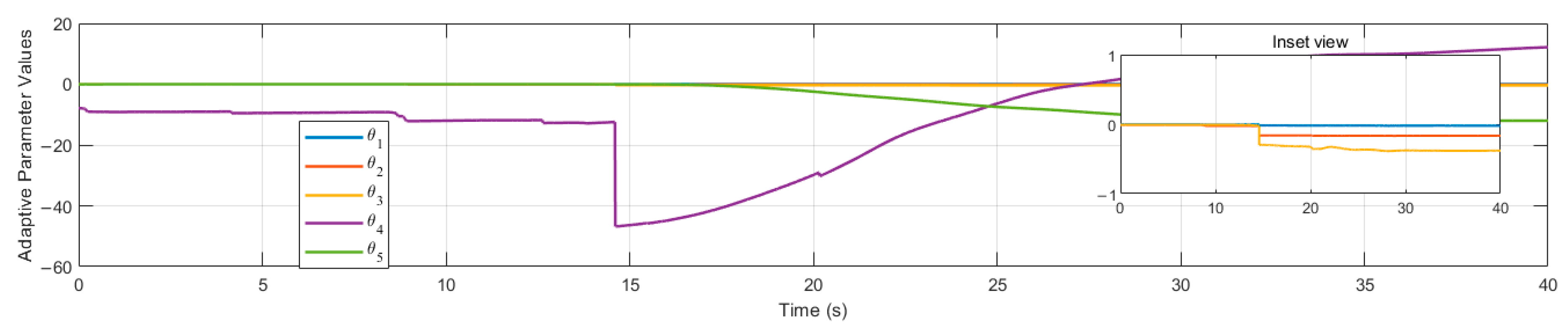
Figure 11 illustrates the time domain evolution of the adaptive parameter estimates in the lower-level robust adaptive controller, where these parameters are associated with uncertainties in the system dynamic model. From the overall response characteristics, most adaptive parameters exhibit rapid convergence during the initial simulation phase (0–5 s), quickly approaching steady values and subsequently maintaining only minor bounded fluctuations. A small subset of parameters undergoes more pronounced step-like adjustments within the interval of approximately t ≈ 10–20 s, after which they rapidly converge to new constant values. Throughout the entire simulation duration, all adaptive parameters remain confined within the bounded interval of [−60, 20], without any indication of divergence or sustained oscillatory behavior. These dynamic responses demonstrate that the proposed adaptive law is capable of achieving fast and effective online estimation and adjustment in the presence of model parameter mismatches and external time-varying disturbances. The rapid convergence and boundedness of the adaptive parameters not only verify the effectiveness of the adaptive mechanism in compensating for parametric uncertainties, but also provide consistent parameter support for the rapid reaching of the sliding surface and the asymptotic convergence of the tracking errors. This behavior is fully consistent with the theoretical analysis based on Lyapunov stability, in which adaptive gains play a critical role in suppressing parameter estimation errors.
Figure 11.
Adaptive parameter evolution of the robust controller.
Moreover, the observed step-like adjustment behavior of certain parameters reflects the controller’s sensitivity to specific uncertainty variations, while the subsequent rapid stabilization indicates the robustness of the adaptive update law in preventing overfitting and parameter drift. Overall, the bounded convergence characteristics of the adaptive parameters further confirm the reliability of the closed-loop system within the input to state stability framework, providing strong theoretical and numerical evidence for the long-term stable operation of the lower-level controller under complex sea conditions.
To improve implementation realism, we consider command channel non idealities applied to the cooperative command before driving the plant, without changing the controller design. Specifically, we impose a two step discrete delay and a first order lag with time constant on both Stewart and gangway command channels. With sampling time , the delayed command is , and the lag is implemented as with . The steady segment tracking performance is summarized in Table 9, showing stable behavior with an expected performance degradation due to additional phase lag.
Table 9.
Steady segment tracking performance under command side non idealities.
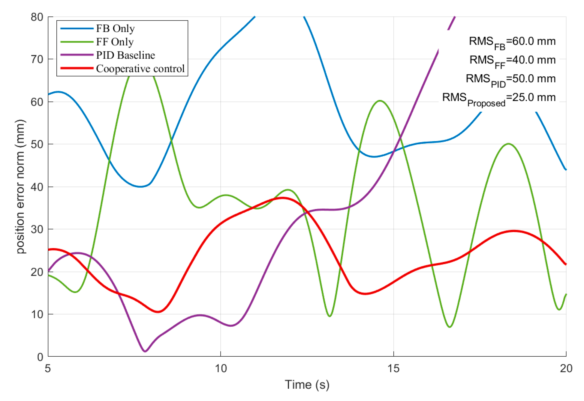
Figure 12 illustrates the time evolution of the norm of the gangway end position error under four control configurations: feedback-only, feedforward-only, a conventional PID baseline, and the proposed cooperative feedforward and feedback strategy. For a focused comparison of transient and short-horizon behaviors relevant to offshore boarding operations, a 20 s window is reported, and the corresponding RMSE values are summarized in the figure.
Figure 12.
Norm of the gangway end position error under different control configurations (FB-only, FF-only, PID baseline, and the proposed cooperative strategy).
As shown in Figure 12, the feedback-only case yields the largest error level (RMSE = 60.0 mm), indicating that pure feedback regulation is insufficient to counteract rapidly varying wave-induced disturbances. The feedforward-only case reduces the error in some intervals (RMSE = 40.0 mm) but exhibits pronounced oscillations, reflecting the sensitivity of purely predictive compensation to modeling mismatch and unmeasured disturbances. The PID baseline achieves moderate performance (RMSE = 50.0 mm) but still suffers from limited disturbance rejection capability and comparatively sluggish transient regulation. In contrast, the proposed cooperative feedforward and feedback strategy consistently maintains the lowest error over the entire horizon (RMSE = 25.0 mm), together with a noticeably smoother error evolution.
This behavior verifies that the proposed architecture effectively leverages the complementarity of feedforward and feedback: the feedforward term anticipates wave-induced motion and attenuates the disturbance at its source, while the feedback term compensates residual errors caused by uncertainties and unmodeled dynamics, thereby improving both tracking accuracy and robustness.
7. Conclusions
This paper proposes a hierarchical cooperative control framework for wave-compensated shipboard boarding operations by integrating disturbance prediction, feedforward reference generation, feedback regulation, and constraint-aware optimization-based allocation. The resulting architecture forms a closed-loop chain from ship motion perception and short-horizon disturbance anticipation to actuator-level tracking. It enables complementary compensation of low-frequency drift and high-frequency wave-induced components while preserving modularity and physical interpretability.
At the algorithmic level, the prediction layer performs online state estimation and separation of low-frequency and high-frequency components using an exponential moving average-based filter and a Kalman filter lookahead predictor. The predicted ship motion is then converted into a disturbance equivalent end effector velocity reference through ship-to-end geometric mapping. The cooperative allocation layer combines the feedforward reference with feedback correction in the task space and solves a quadratic program to distribute motion commands between the Stewart platform and the three-degrees-of-freedom gangway under actuator and safety constraints, including velocity limits and stroke boundaries. This design mitigates actuator overload and maintains feasible actuation.
Simulation studies under representative JONSWAP sea states demonstrate that the proposed cooperative strategy yields consistently lower end effector tracking errors than feedback only, feedforward only, and proportional integral derivative baselines. The root mean square error reduction reaches approximately 37.5 percent to 58.3 percent across the tested cases. Although occasional peaks in instantaneous end effector velocity may occur near disturbance extrema due to residual prediction errors and active constraint enforcement, the overall closed-loop response remains bounded and stable.
This study is validated through high-fidelity simulations. Future work will focus on experimental verification and hardware in the loop evaluation to further assess practical uncertainties, including actuator dynamics, time delays, sensor noise, and communication constraints. Additional smoothness-related constraints will also be investigated to improve motion comfort and actuator longevity.
Author Contributions
Conceptualization, L.T.; methodology, L.T. and X.Y.; software, L.T.; validation, L.T. and B.C.; formal analysis, L.T. and X.Y.; investigation, L.T. and B.C.; resources, J.F.; data curation, B.C.; writing—original draft, L.T.; writing—review and editing, C.C. and X.Y.; visualization, L.T. and J.F.; supervision, C.C.; project administration, C.C. and X.Y. All authors have read and agreed to the published version of the manuscript.
Funding
The Key-Area Research and Development Program of Guangdong Province, China (grant no. 2021B0707040002).
Data Availability Statement
The original contributions presented in this study are included in the article. Further inquiries can be directed to the first author or the corresponding author.
Conflicts of Interest
Author Xinkuan Yan was employed by the company China Merchants Marine and Offshore Research Institute Co., Ltd. The remaining authors declare that the research was conducted in the absence of any commercial or financial relationships that could be construed as a potential conflict of interest.
References
- Gao, X.; Li, T. Dynamic Positioning Control for Marine Crafts: A Survey and Recent Advances. J. Mar. Sci. Eng. 2024, 12, 362. [Google Scholar] [CrossRef] [Scilit]
- Du, J.; Hu, X.; Krstic, M.; Sun, Y. Robust Dynamic Positioning of Ships with Disturbances under Input Saturation. Automatica 2016, 73, 207–214. [Google Scholar] [CrossRef] [Scilit]
- Ianagui, A.S.S.; Tannuri, E.A. Cooperative Sliding Mode Control Applied to a Fleet of DP Vessels. IFAC-Pap. 2015, 48, 299–304. [Google Scholar] [CrossRef] [Scilit]
- Aktas, U.; Tatlicioglu, E.; Zergeroglu, E. A Composite Adaptive Tracking Controller for Dynamically Positioned Surface Vessels with Only Position Measurements. Ocean Eng. 2022, 254, 112386. [Google Scholar] [CrossRef] [Scilit]
- Yin, R.; Xie, W.; Wen, Y.; Zhang, C.; Chen, W.; Zhang, W. Robust Wave Compensation Controller Design for an Active Hexapod Platform with Time-Varying Input Delays. Ocean Eng. 2023, 274, 114084. [Google Scholar] [CrossRef] [Scilit]
- Cai, Y.; Zheng, S.; Liu, W.; Qu, Z.; Zhu, J.; Han, J. Sliding-Mode Control of Ship-Mounted Stewart Platforms for Wave Compensation Using Velocity Feedforward. Ocean Eng. 2021, 236, 109477. [Google Scholar] [CrossRef] [Scilit]
- Wang, Y.; Wei, Y.; Gao, W.; Ma, T.; Han, Y. Ocean Wave Active Compensation Analysis for Redundant Hybrid Boarding System: A Multi-Task Motion Planning Method. J. Mar. Sci. Eng. 2023, 11, 708. [Google Scholar] [CrossRef] [Scilit]
- Chen, Z.; Liu, X.; Ji, X.; Gui, H. Real-Time Prediction of Multi-Degree-of-Freedom Ship Motion and Resting Periods Using LSTM Networks. J. Mar. Sci. Eng. 2024, 12, 1591. [Google Scholar] [CrossRef] [Scilit]
- Gong, J.; Xu, J.; Xu, L.; Hong, Z. Enhancing Motion Forecasting of Ship Sailing in Irregular Waves Based on Optimized LSTM Model and Principal Component of Wave-Height. Front. Mar. Sci. 2025, 12, 1497956. [Google Scholar] [CrossRef] [Scilit]
- Zhao, R.; Hu, X. A correction method for the motion measurement of the ship borne mechanical platform based on multi sensor fusion. Machines 2023, 11, 847. [Google Scholar] [CrossRef] [Scilit]
- Yan, T.; Xu, Z.; Yang, S.X.; Gadsden, S.A. Formation Control of Multiple Autonomous Underwater Vehicles: A Review. Intell. Robot. 2023, 3, 1–22. [Google Scholar] [CrossRef] [Scilit]
- Jin, Z.; Meng, L.; Guerrero, J.M.; Han, R.R. Hierarchical Control Design for Shipboard Power System with DC Distribution and Energy Storage Aboard Future More-Electric Ships. IEEE Trans. Ind. Inform. 2018, 14, 703–714. [Google Scholar] [CrossRef] [Scilit]
- Zhao, Y.; Sun, H.; Wang, X.; Yang, D.; Jiao, T. Distributed Leader-Following Bipartite Consensus for One-Sided Lipschitz Multi-Agent Systems via Dual-Terminal Event-Triggered Mechanism. Neural Netw. 2025, 181, 106808. [Google Scholar] [CrossRef] [Scilit] [PubMed]
- Skulstad, R.; Li, G.; Fossen, T.I.; Zhang, H. Constrained control allocation for dynamic ship positioning using deep neural network. Ocean Eng. 2023, 279, 114434. [Google Scholar] [CrossRef] [Scilit]
- Wang, Y.; Wei, Y.; Han, Y. An active hybrid compensation control method for a redundantly hybrid boarding platform during docking. Ocean Eng. 2025, 341, 122671. [Google Scholar] [CrossRef] [Scilit]
- Yin, L.; Qiao, D.; Li, B.; Liang, H.; Yan, J.; Tang, G.; Ou, J. Modeling and controller design of an offshore wind service operation vessel with parallel active motion compensated gangway. Ocean Eng. 2022, 266, 112999. [Google Scholar] [CrossRef] [Scilit]
- Fossen, T.I.; Fjellstad, O.E. Nonlinear modelling of marine vehicles in six degrees of freedom. Math. Model. Syst. 1995, 1, 17–27. [Google Scholar]
- Feng, K.; Wang, J.; Wang, X.; Wang, G.; Wang, Q.; Han, J. Adaptive state estimation and filtering for dynamic positioning ships under time varying environmental disturbances. Ocean Eng. 2024, 303, 117798. [Google Scholar] [CrossRef] [Scilit]
- Hasselmann, K.; Barnett, T.P.; Bouws, E.; Carlson, H.; Cartwright, D.E.; Enke, K.; Ewing, J.A.; Gienapp, H.; Hasselmann, D.E.; Kruseman, P.; et al. Measurements of Wind Wave Growth and Swell Decay During the Joint North Sea Wave Project (JONSWAP); Deutsches Hydrographisches Institut: Hamburg, Germany, 1973.
- Skandali, D.; Lourens, E.; Ogink, R.H.M. Calibration of response amplitude operators based on measurements of vessel motions and directional wave spectra. Mar. Struct. 2020, 72, 102774. [Google Scholar] [CrossRef] [Scilit]
- Huang, X.; Tang, J.; Shen, Y. Long time series of ocean wave prediction based on the PatchTST model. Ocean Eng. 2024, 301, 117572. [Google Scholar] [CrossRef] [Scilit]
- Tao, J.; Xu, Y.; Chen, Y.; Cheng, P.; Zhang, H.; Wang, J.; Zhou, H. Multi-Objective Structural Parameter Optimization for Stewart Platform via NSGA-III and Kolmogorov–Arnold Network. Machines 2025, 13, 887. [Google Scholar] [CrossRef] [Scilit]
- Chen, X.; Jiao, Y.; Yuan, X.; Meng, Z.; Zhang, L.; Liu, X. An online dual loop AMPC strategy for wave compensation of an electro hydraulic servo Stewart platform. Control Eng. Pract. 2025, 165, 106540. [Google Scholar] [CrossRef] [Scilit]
- Li, M.; Liu, W.; Lin, D.; Du, J. Extended state observer based robust cascade positioning control for the tip of offshore gangways. In Proceedings of the 2023 42nd Chinese Control Conference (CCC), Tianjin, China, 24–26 July 2023; pp. 3030–3035. [Google Scholar]
- Chen, S.; Xie, P.; Liao, J. Cascade NMPC PID control strategy of an active heave compensation system for a ship mounted offshore crane. Ocean Eng. 2024, 302, 117648. [Google Scholar] [CrossRef] [Scilit]
- Zhang, L.; Du, H.; Qin, Z.; Zhao, Y.; Yang, G. Real time optimized inverse kinematics of redundant robots under inequality constraints. Sci. Rep. 2024, 14, 81174. [Google Scholar] [CrossRef] [Scilit]
- Guptasarma, S.; Strong, M.; Zhen, H.; Kennedy, M., III. J PARSE: Jacobian based projection algorithm for resolving singularities effectively in inverse kinematic control of serial manipulators. arXiv 2025, arXiv:2505.00306. [Google Scholar] [CrossRef] [Scilit]
- Huo, Z.; Yuan, M.; Zhang, S.; Zhang, X. Observer based adaptive robust force control of a robotic manipulator integrated with an external force torque sensor. Actuators 2025, 14, 116. [Google Scholar] [CrossRef] [Scilit]
- Jokar, H.; Naghipour, A.; Jeloudari, I. A new adaptive robust control scheme for trajectory tracking of robot manipulators with uncertain dynamics model. IET Control Theory Appl. 2025, 19, e70039. [Google Scholar] [CrossRef] [Scilit]
- Kwakernaak, H. Robust control and H infinity optimization. Automatica 1993, 29, 255–273. [Google Scholar] [CrossRef] [Scilit]
- Kipchirchir, E.; Söffker, D. IPC based robust disturbance accommodating control for load mitigation and speed regulation of wind turbines. Wind Energy 2024, 27, 382–402. [Google Scholar] [CrossRef] [Scilit]
- Xue, Y.; Zhao, P. Input to state stability and stabilization of nonlinear impulsive positive systems. Mathematics 2021, 9, 1663. [Google Scholar] [CrossRef] [Scilit]

Disclaimer/Publisher’s Note: The statements, opinions and data contained in all publications are solely those of the individual author(s) and contributor(s) and not of MDPI and/or the editor(s). MDPI and/or the editor(s) disclaim responsibility for any injury to people or property resulting from any ideas, methods, instructions or products referred to in the content. |
© 2026 by the authors. Licensee MDPI, Basel, Switzerland. This article is an open access article distributed under the terms and conditions of the Creative Commons Attribution (CC BY) license.