2. Literature Review
Sulfur-alkaline wastewater from oil refining and petrochemical plants is generated during alkaline cleaning of pyrolysis gases, hydrotreating, catalytic cracking and other processes where sodium hydroxide solutions are used to remove hydrogen sulfide and mercaptans [
1,
2]. These wastewaters are characterized by extremely high pH values—up to 12–14, a significant content of sulfide and hydrosulfide sulfur—up to 20 g/L, as well as the presence of organic pollutants—petroleum products, phenols, formaldehyde, methanol and benzene. A real process effluent may have a pH of 13.06, a sulfide content of approximately 5000 mg/dm
3, and a COD of 12,600 mg/dm
3, which is many times higher than the maximum permissible concentration and confirms the need for intensive treatment methods.
Traditional approaches to detoxifying sulfur-alkaline waste include reagent-based methods, such as acid neutralization, oxygen oxidation, ozonation, and chlorination, thermal methods, and physicochemical methods [
2,
3]. Neutralization with mineral acids converts sulfides into molecular hydrogen sulfide, which is released into the gas phase, requiring its capture and processing; for example, into elemental sulfur using the “Claus process”. This process produces neutral salts—sodium sulfate or chloride—that increase water mineralization, and the process itself is accompanied by equipment corrosion and foaming [
2]. Oxidation with atmospheric oxygen under autoclave conditions—150–200 °C, 1.5–2.5 MPa—allows for an increase in the degree of oxidation, but energy consumption and the need to use expensive corrosion-resistant materials limit its application [
2]. During atmospheric oxidation, as shown in [
1], the sulfide removal efficiency averages 88.8%—a reduction from 20 to 3300 to 3–300 mg/dm
3. However, the thiosulfate content increases by a factor of 5.8, from 1 to 300 to 10–1500 mg/dm
3.
Ozonation, despite the high oxidation potential of ozone (2.07 V), is characterized by significant energy consumption for its generation (up to 23 kW·h/kg O
3) and the need to utilize residual ozone [
3]. In the study [
3], diluted sulfur-alkaline waste was purified with ozone in the presence of hydrogen peroxide. For the initial characteristics of the effluent of pH 11.4, COD 820 mg/dm
3, sulfides 469 mg/dm
3, sulfates 69 mg/dm
3, where in 60 min the COD decreases to 208 mg/dm
3, a decrease of 3.94 times, and the dependence of the concentration of sulfide and sulfate ions on time, it is clear that sulfides are almost completely oxidized in 30 min, the residual concentration is 20 mg/dm
3, the efficiency is 95.7%, and sulfates increase to 1413 mg/dm
3.
The sulfur material balance showed that the initial sulfur content of 493 mg/dm
3 after treatment was 486 mg/dm
3—a discrepancy of 7 mg/dm
3. However, the residual sulfide concentration of 20 mg/dm
3 still significantly exceeds the MPC of 0.003 mg/dm
3, while the sulfate concentration of 1413 mg/dm
3—the standard of 500 mg/dm
3 [
3]—is significantly higher than the MPC. Thus, none of the reagent methods simultaneously provides deep purification and the extraction of valuable components.
Thermal methods—concentration by evaporation followed by combustion of the organic concentrate or direct combustion of sulfur-alkaline waste—allow for the almost complete destruction of organic pollutants, but are characterized by extremely high energy consumption and the problem of equipment corrosion [
2]. Sorption methods using activated carbons, zeolites, and clay minerals are effective in removing oil products and some organic compounds, but are not effective enough for low-molecular polar compounds and sulfides [
4]. A hybrid technology for water purification by dosing powdered activated carbon of the OU-A brand was studied in [
5]. It was shown that, at a carbon pulp dose of 3 mg/L, color decreased by 35%, and residual chlorine by 10%; at a dose of 10 mg/L, the reduction in color reached more than 35%, residual chlorine by 30%, permanganate oxidizability by 5–25%, and total organic carbon by more than 15%. However, sorption does not solve the problem of sulfide removal and requires regeneration or disposal of the spent sorbent [
5].
Modified bentonite, as shown in [
6], allows COD to reduce from 5000 to 90 mg/dm
3—efficiency of 98.2%, biochemical oxygen demand—from 1000 to 3 mg/dm
3, and turbidity from 18,000 to 6 nephelometric turbidity unit at an optimal pH of 2.5; however, high acidity of the medium and the need for subsequent neutralization limit the application of this method for real alkaline wastewater. Biosorption of ammonia using Eichhornia crassipes root powder, studied in [
7], showed a maximum efficiency of NH
3 removal of 79% in a batch mode, sorbent dose of 5 g/L, pH 6, time 30 min, and up to 94.1% in a column mode when treating real wastewater, a decrease from 6.3 to 0.37 mg/L. However, this method is focused primarily on the removal of ammonium nitrogen and is ineffective for sulfides. Other aspects of industrial wastewater treatment, including alternating electrolysis for electrode life extension [
8], life cycle assessment of activated sludge systems [
9], combined natural systems for organics and phosphorus removal [
10], application of coagulants for textile wastewater [
11], bio-electrochemical treatment of food wastewater with copper recovery [
12], and reviews of water electrolysis technologies for green hydrogen production [
13,
14], are discussed in the relevant publications.
Membrane methods—microfiltration, ultrafiltration, nanofiltration, and reverse osmosis—are capable of providing high purification levels, but their use for sludge is limited by high osmotic pressure, membrane susceptibility to contamination by organic matter and sulfides, and concentrate disposal issues [
4]. The use of ocher waste, an iron-containing sludge, for phosphate and sulfide control in anaerobic systems was studied in [
15]. Ochre dosing at 1.0 g Fe
3+/L in periodic tests reduced phosphate concentrations by 57%, while feeding 2.5–5 g Fe
3+/day to a pilot reactor immediately reduced the H
2S content in biogas from >2000 ppm to 570 ppm. However, this method does not involve alkali regeneration and does not yield pure products. Hybrid membrane systems combining reverse osmosis and electrodialysis are considered a promising solution for the deep processing of highly mineralized wastewater [
16]. A comparison of various configurations (single-stage RO, RO-ED, NF-RO-ED) showed that the NF-RO-ED system is the most effective, producing a concentrate with a salt content of up to 300 g/L with an energy consumption of 6.9 kW·h/m
3 and a water recovery of 69%. However, such systems require preliminary purification from organic contaminants and sulfides, which limits their direct use for sulfur-alkaline wastewater [
16].
In recent decades, increasing attention has been paid to electrochemical purification methods, which allow the generation of oxidants directly in solution without the addition of reagents, and also combine purification with the production of valuable products—hydrogen and alkali [
17,
18,
19]. Anodic oxidation on inert electrodes, such as Pt, IrO
2, or active materials, for example, Ni, Co, and their oxides, allows the destruction of both inorganic sulfides and organic pollutants. The review [
17] presents the main characteristics of proton exchange membrane (PEM) electrolyzers: current density of 1–2 A/cm
2, cell voltage of 1.4–2.5 V, service life of up to 60.000 h. However, the use of noble metals—Pt, Ir—and titanium current leads makes this technology expensive. A more economical alternative is alkaline electrolysis with anion-exchange membranes (AEMWE), which allows the use of base metals—Ni, Co, Fe—as catalysts [
18,
19,
20]. In [
18], new types of anion-exchange membranes and nickel electrodes for AEMWE were developed. The authors [
18] also demonstrated that the use of the heterogeneous “KS-1” catalyst allows for a reduction in sulfide sulfur content from 50,000 to 50 mg/dm
3, i.e., an efficiency of 99.9%, while the homogeneous catalyst allows for a sulfide oxidation rate of up to 99.9%. However, in both cases, sulfates accumulate in the treated effluent, and the catalysts are expensive and require regeneration [
1].
The catalytic activity of nickel and nickel-iron anodes for AEMWE was studied in detail in [
21]. In a three-electrode cell in 1 M KOH, the Ni
90Fe
10 catalyst showed an oxygen evolution overpotential of 341 mV at 10 mA/cm
2, which is only slightly higher than that of Ir black (295 mV). In a real AEMWE cell at 50 °C and 1 M KOH, the Ni
90Fe
10 electrode with 6 mg/cm
2 achieved a current density of 2 A/cm
2 at a voltage of 1.85–1.90 V, which is comparable to Ir black at half the load. When the KOH concentration was reduced to 0.1 M, only Ni
90Fe
10 remained functional, reaching 2 A/cm
2 at 1.99 V, while Ir black could not provide such a current density. These results confirm the potential of using Ni-Fe catalysts in alkaline environments for the oxidation of pollutants. An improved nickel gas diffusion anode for AEMWE was proposed in [
22], which allows for the achieving of a current density of 2.6 A/cm
2 at 2 V, which is comparable to PEM electrolyzers. The authors [
23] developed a solid Ir-Ru solution for operation in low-alkaline environments—0.05 M KOH, providing a cell voltage of 1.75 V at 1 A/cm
2 and stability of more than 1000 h. These achievements are important for the creation of stable electrodes for the treatment of aggressive wastewater, where the alkali concentration can vary over a wide range [
23].
One of the key problems when working with aggressive environments is the degradation of ion-exchange membranes. In [
18], membranes were tested by exposing them to sulfur-alkaline solutions for 18 days. These tests showed that the anion-exchange membrane changed color and became brittle, while the cation-exchange membrane retained its properties. After washing in distilled water, the anion-exchange membrane remained degraded, confirming its unsuitability for use in sulfur-alkaline solutions.
The problem of parasitic proton transfer through anion-exchange membranes in bipolar membrane electrodialysis (BMED) was studied in detail in [
24]. The authors compared two types of commercial anion-exchange membranes (AOMs): a standard strongly basic anion-exchange membrane (ASE) with quaternary ammonium groups, 16.0% moisture content, and 2.77 Ohm·cm
2 resistance, and a proton-blocking weakly basic anion-exchange membrane (ACM) with tertiary ammonium groups, 15.0% moisture content, and 3.23 Ohm·cm
2 resistance. Measurements in a small-sized electrodialysis cell showed that at an HCl concentration of 0.2 mol/L, the H
+ flux through ASE was 1.30 · 10
−8 mol/(m
2·s), while through ACM it was only 0.01 · 10
−8 mol/(m
2·s), i.e., more than 100 times lower. With an increase in the HCl concentration to 0.5 mol/L, the difference decreased to 10 times—5.42 · 10
−8 versus 0.62 · 10
−8 mol/(m
2·s), but remained significant. In the case of H
2SO
4, the proton flux was significantly higher for both membranes due to the lower mobility of sulfate ions, and the difference between ASE and ACM decreased to 3–4 times—at 0.5 mol/L H
2SO
4, the flux through ASE was 78.6 · 10
−8, and through ACM was 24.7 · 10
−8 mol/(m
2·s). These data indicate that the ability of the membrane to block protons strongly depends on the nature of the anion in the solution.
BMED tests [
24] confirmed that when using NaCl as a feed solution, the ACM membrane provides a higher current efficiency and a lower specific energy capacity.
When working with Na
2SO
4, despite the higher current efficiency of ACM (64.6% versus 61.2% for ASE), the higher ohmic resistance of the ACM membrane results in a higher cell voltage (2.20 V versus 1.91 V) and, consequently, higher energy capacity. Thus, the study [
24] clearly demonstrates that the selection of the optimal membrane depends on the specific ionic composition of the treated water, and the efficiency of the BMED is a complex function of both the selectivity and electrical resistance of the membrane. These findings are directly relevant for the development of stable electrochemical systems for aggressive environments, since real sulfur-alkaline wastewater contains highly mobile hydroxide ions, as well as sulfides, carbonates, and organic anions.
Rational water use in the oil industry and the creation of closed water cycles is discussed in [
16]. The authors note that refinery water supply systems require water quality maintenance at the following levels: petroleum products 25–30 mg/L, suspended solids 25 mg/L, sulfates 500 mg/L, chlorides 300 mg/L, and carbonate hardness no more than 5 mg-eq/L. Achieving these levels requires deep purification, including the removal of sulfides and organic contaminants.
Sulfur-alkaline wastewater from petrochemical plants has a complex, multi-component, aggressive composition with high concentrations of contaminants. Consequently, traditional methods of treating them are either impossible or extremely difficult; either a comprehensive treatment program or the use of electrochemical technologies is required. Electrochemical methods offer a significant advantage over other approaches: they not only neutralize wastewater but also extract valuable products from it, oxidize sulfides to elemental sulfur, and decompose organic matter. Therefore, the development and optimization of an efficient electrochemical system for processing sulfur-alkaline wastewater is a pressing task.
3. Materials and Methods
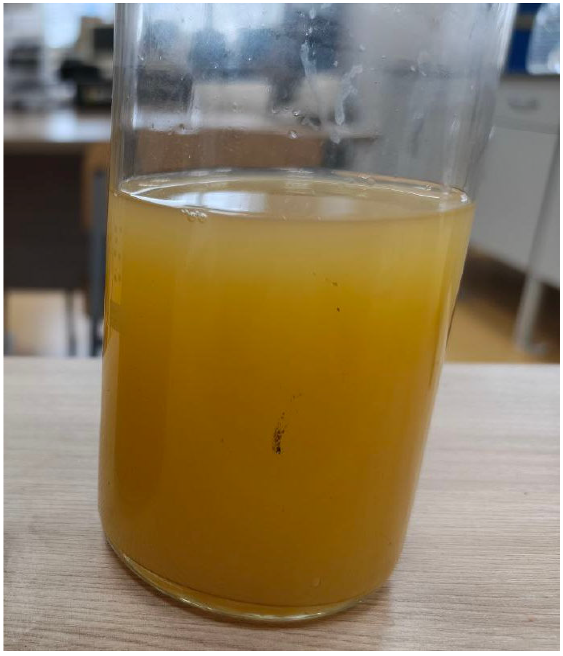
A process effluent from the monomer production facility of a petrochemical plant—specifically, the stream downstream of the “red oil” removal unit—was selected for electrodialytic purification and separation. The volume of this alkaline wastewater generated during production amounts to approximately 5 m
3/h (
Figure 1).
The solution is turbid and yellow-green in color. Filtration through activated carbon does not eliminate the turbidity as it is presumed to be an emulsion of an organic fraction in water.
The industrial wastewater was analyzed using physicochemical methods, including: spectrophotometry on a Shimadzu UV-1800 UV-Vis spectrophotometer (Kyoto, Japan); IR spectrophotometry on a Shimadzu IRAffinite-1S FTIR spectrometer (Kyoto, Japan); gas chromatography–mass spectrometry (GC-MS) on a system based on the “Kristallux-4000M” chromatograph (Scientific and production company "Meta-chrome", Yoshkar-Ola, Russia); and total organic carbon (TOC) analysis on an Elementar Vario TOC Select analyzer (Langenselbold, Germany). The results of the wastewater composition analysis are presented in
Table 1.
The organic fraction consists of major components—petroleum products, formaldehyde, methanol, benzene, and toluene—and minor components, comprising 58 organic compounds of various classes identified through qualitative analysis of the sulfide-alkaline wastewater using gas chromatography coupled with mass spectrometry detection.
Thus, the raw effluent can be characterized as a highly concentrated, sulfide-bearing, alkaline organic system that requires intensive treatment methods to meet regulatory discharge standards or to enable its reuse within the industrial process cycle.
Consequently, while electrodialysis is theoretically feasible, it necessitates pilot-scale testing to assess the actual efficiency and long-term stability of the membranes and structural materials under these specific conditions. Favorable factors include high electrical conductivity (specific electrical conductivity up to 100 mS/cm) and the presence of alkalis in ionic form (hydrate alkalinity up to 150 mg-eq/L). However, the high sulfide content (up to 5 g/L) may lead to corrosion of electrodes and membranes, as well as the formation of sulfide precipitates within the cells. High organic contamination (COD up to 13 g/L; TOC up to 300 mg/L) may result in membrane fouling and a reduction in process efficiency. The presence of suspended solids (turbidity up to 2500 FTU) may cause clogging of the cells, while high carbonate hardness can lead to the deposition of carbonates on the membranes.
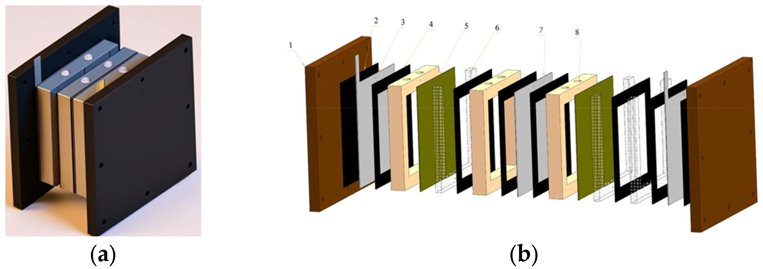
To conduct research on the electrochemical separation of solutions, a prototype laboratory electromembrane apparatus was fabricated; this device constitutes a specialized multi-chamber unit. Structurally, the apparatus is designed as a stack assembly comprising two compression plates made of textolite, secured together by stainless steel tie rods to ensure the reliable fixation of the internal components. The internal volume is defined by an alternating arrangement of ion-exchange membranes, bipolar electrodes, and polymer spacer frames, which collectively form sealed working chambers. To enhance mass transfer, turbulence-generating separators are positioned within the chamber cavities. The apparatus is equipped with ports and fittings for the inlet and outlet of process solutions. Depending on the specific research configuration, the apparatus can accommodate between 3 and 10 working chambers. For the experimental trials, various assembly configurations of the membrane apparatus were utilized, incorporating CAM and AAM IONSEP membranes (manufactured in China). The tensile strength of the membranes was measured on the universal testing machine SNTF-Lab (LTD “ScienTific”, Saint Petersburg, Russia). The specific surface electrical resistance of the membranes was measured on ST2258C four-probe resistivity (LTD “Suzhou Jingge Electronic Company”, Suzhou, China) and surface resistance meter. All materials in contact with the solutions are chemical and corrosion resistant. The overall dimensions of the assembled apparatus are 10 cm in width and 10 cm in height, making it a compact and convenient tool for laboratory-scale modeling of electrodialysis processes, studying ion transport kinetics, and optimizing liquid waste treatment protocols prior to technological scale-up. The structural design and internal component layout of the electromembrane cell are illustrated in
Figure 2.
The geometric dimensions of the active zone—the width and height of the working section of the chamber—are 80 · 80 mm. The effective membrane area is 0.0064 m2. The interelectrode distance across one chamber is 5 mm, and the total ion path between the anode and cathode through both chambers and the membrane is 10 mm. The frames are made of chemically resistant polypropylene, and the turbulent separator meshes are 2 mm thick and have a 2 · 2 mm mesh size. All seals are made of silicone rubber.
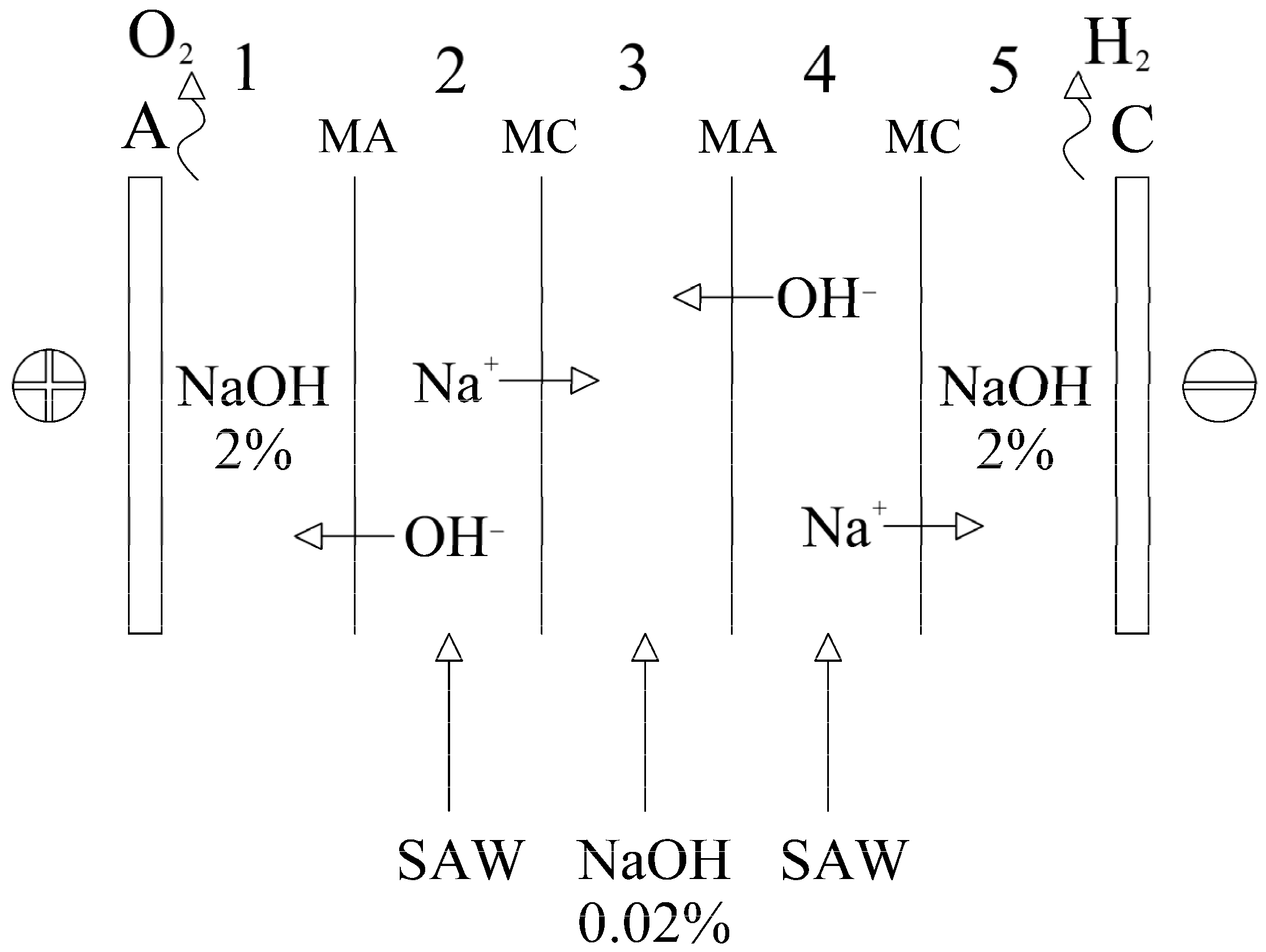
The work was initiated using the method of electrodialytic separation and concentration of alkali from spent caustic solutions.
The chambers of the apparatus designated for working and rinse solutions are filled with the corresponding solutions of known concentrations. The assembly schematic of the apparatus for the electrodialytic separation and concentration of alkali mode is presented in
Figure 3.
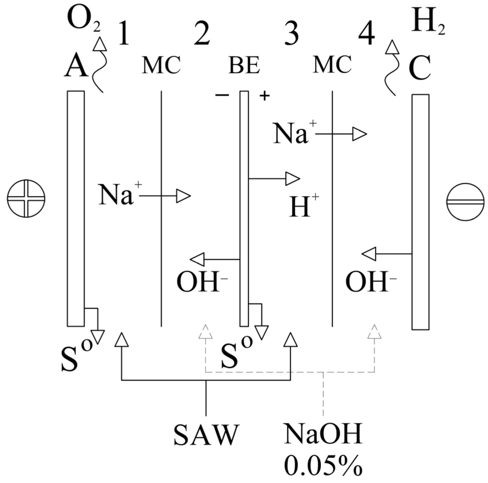
The next series of experiments was conducted in the mode of bipolar membrane electrolysis (
Figure 4). In this case, only cation-exchange membranes are used. A nickel plate serves as the bipolar electrode; this can be replaced by a titanium-iridium or titanium-platinum plate, which are more resistant to corrosion and degradation.
The bipolar electrode functioned as an anode relative to chamber 3 and as a cathode relative to chamber 2, thereby enabling the sequential flow of current without the need for additional external power sources for the intermediate chambers.
The sulfur formed coagulates and precipitates, allowing for its subsequent separation via mechanical filtration.
Concurrently, at the cathodes (both monopolar and bipolar) in chambers 2 and 4—which were filled with distilled water—the water reduction reaction took place, resulting in the evolution of gaseous hydrogen and the formation of hydroxide ions in Equation (2):
Under the influence of an electric field, sodium cations present in the initial sulfide-alkaline wastewater migrated through the cation-exchange membranes from the anode compartments (1 and 3) into the cathode compartments (2 and 4, respectively). Sodium hydroxide accumulated in the cathode compartments in Equation (3):
Thus, this electrodialyzer design enables the simultaneous execution of three target processes:
Purification of sulfide-alkaline wastewater to produce elemental sulfur in the anode chambers;
Recovery of a sodium hydroxide solution suitable for reuse within the technological cycle of oil refining operations [
2];
Production of high-purity hydrogen (at least 99.9%).
During the experimental investigations, changes in the physicochemical characteristics of the sulfide-alkaline wastewater resulting from electrochemical treatment in a four-compartment electrodialyzer with bipolar electrodes were evaluated. Quality control of the initial and treated samples was performed based on the following parameters: pH, specific electrical conductivity, total salinity, total and carbonate alkalinity, sulfide ion content, and chemical oxygen demand (COD). Measurements were conducted in accordance with standard analytical procedures.
Calculated Process Characteristics
The efficiency of electrochemical processing was assessed using the following parameters:
Current efficiency (η, %) for components (sodium hydroxide, sulfides, organic substances) was calculated as the ratio of the amount of substance actually obtained to the theoretical amount, determined by Faraday’s law in Equation (4):
where n
exp is the amount of substance transferred to the purified solution during the experiment (mol); F is the Faraday constant (96,485 C/mol); I is the current (A); t is the electrolysis time (s).
Specific energy consumption (W, kW·h) was calculated using the formula in Equation (5):
where U is the cell voltage (V).
The current density (j, A/m
2) was determined as the ratio of the current strength to the working area of the electrode (S, m
2) in Equation (6):
The specific alkali transfer (P, kg/(m
2·h)) per unit membrane area was calculated based on the mass of accumulated NaOH in Equation (7):
where m is the mass of NaOH transferred through the membrane (kg); S
m is the working area of the membrane (m
2).
The degree of extraction of components and residual concentrations were determined analytically based on the difference in indicators before and after the experiment.
4. Results
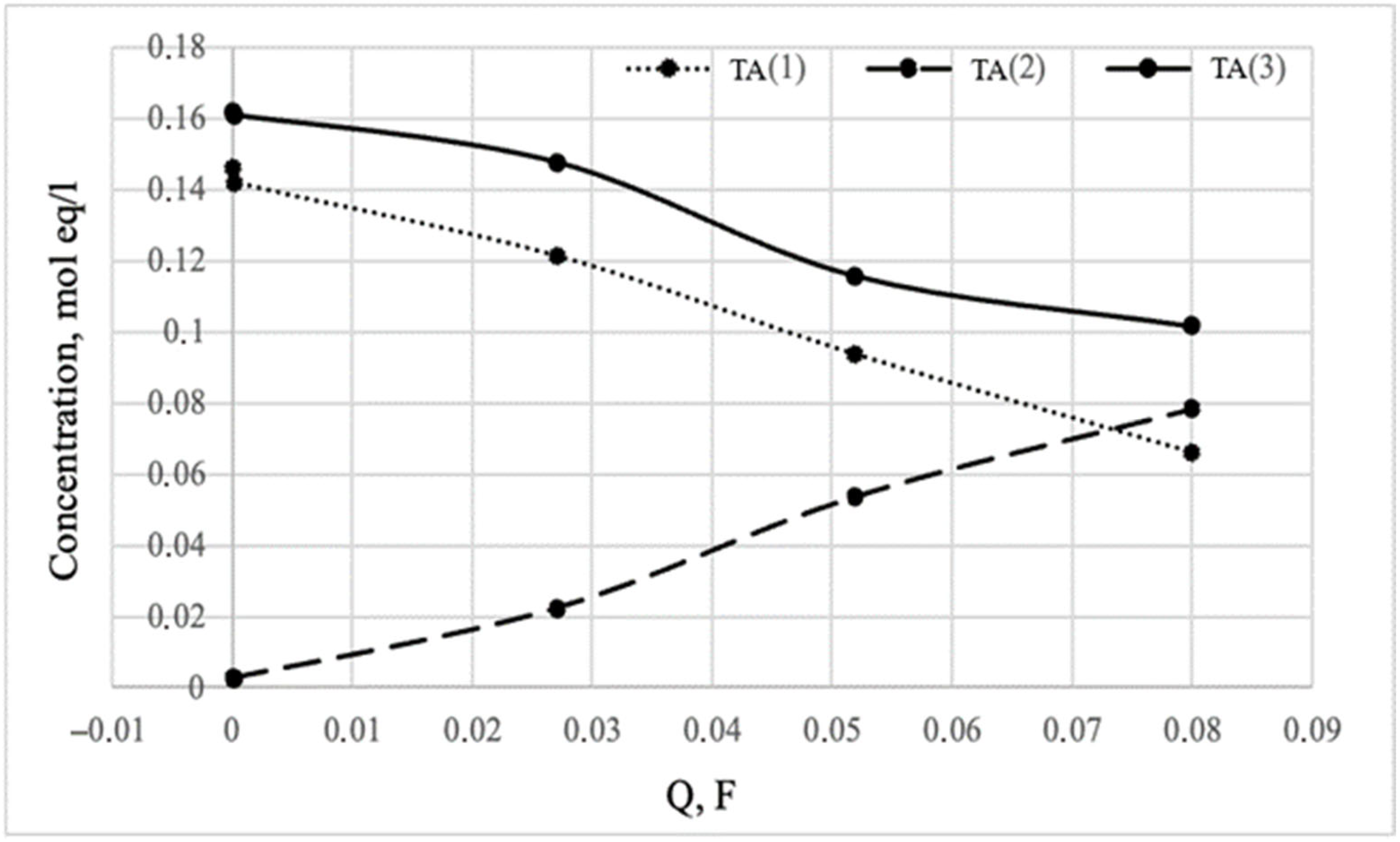
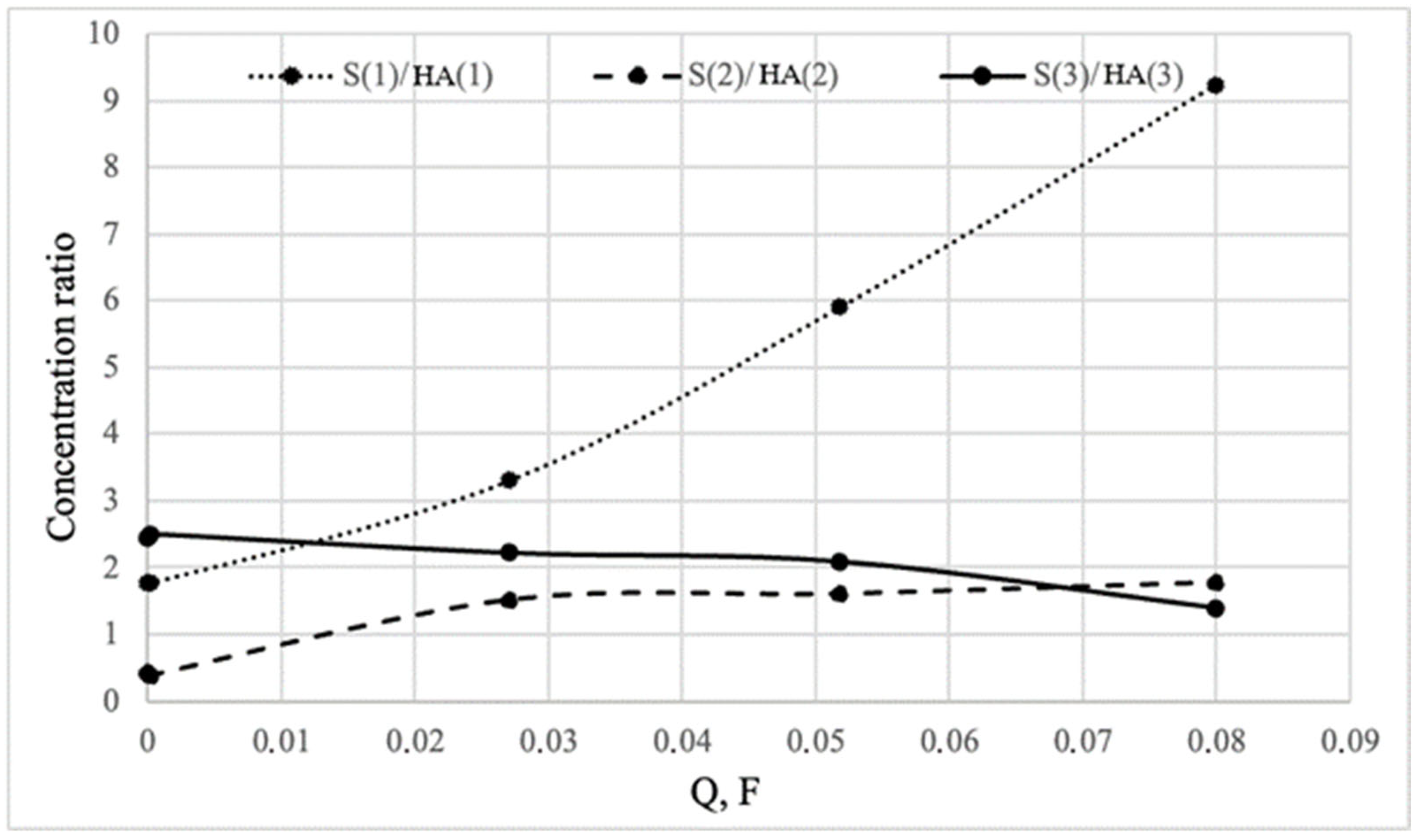
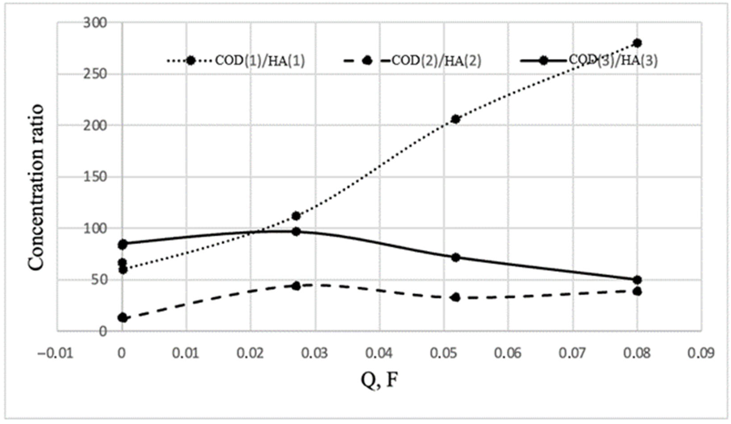
Based on the results of the electrodialysis separation using cation- and anion-exchange membranes (as shown in
Figure 3), graphs were plotted illustrating the changes in the concentrations of total and hydrate alkalinity, COD, and sulfides (
Figure 5,
Figure 6 and
Figure 7).
The results obtained from the electrodialysis concentration process led to the conclusion that, while alkalinity is indeed separated and concentrated, the process suffers from a number of serious and inherent drawbacks:
The process is non-selective. Along with the alkalinity, the primary contaminants—sulfides and organic substances—are also transported. Consequently, the separated alkalinity is no purer than it was in the original wastewater stream.
This method does not incorporate any oxidation of sulfides or organic matter; thus, all toxic components remain present.
During the trials, signs of degradation were observed in the anion-exchange membranes.
Using an electrodialyzer with bipolar electrodes, it was possible to obtain the desired results; namely, to separate sulfide-alkaline wastewater in chambers 1 and 3 into a practically pure alkaline solution with the required concentration of sodium alkali and an insignificant content of impurities—sulfides and organic substances in chambers 2 and 4 (
Table 2).
Electrochemical treatment was carried out in two stages. Since it was necessary to achieve a certain alkali concentration (up to 2.5%) in the target alkaline solution in chambers 2 and 4, it became necessary to replace the sulfide-alkaline effluent with new solutions in chambers 1 and 3 due to their depletion of hydrate alkalinity during the first stage of testing.
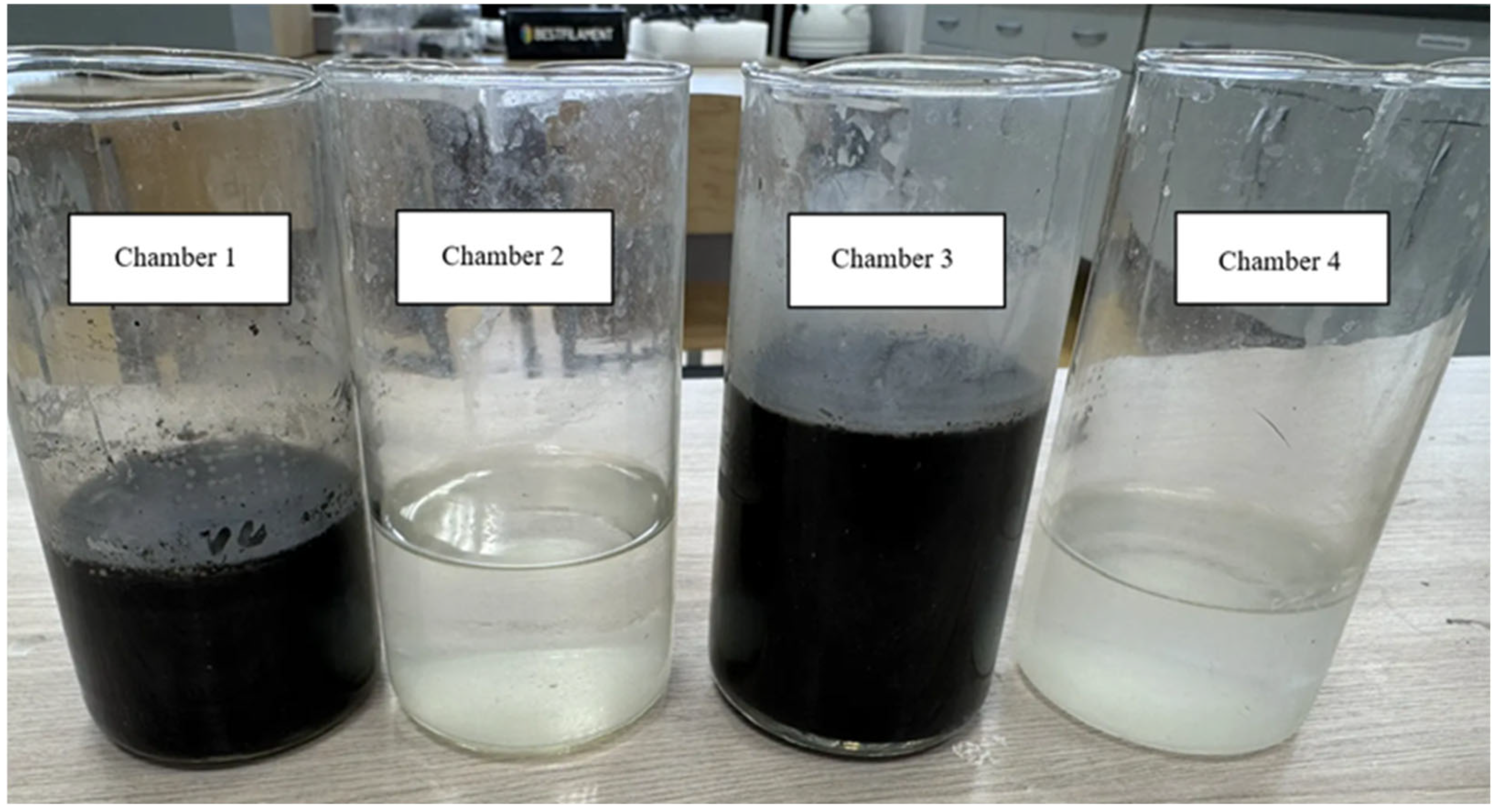
Alkali accumulation occurred in cathode chambers 2 and 4. In chamber 2, total alkalinity increased to 456 mg-eq/L, with the hydroxide form predominating (442 mg-eq/L). The SEC reached 83.8 mS/cm with a total salinity of 41.8 g/L. Sulfide content remained low (52.3 mg/L), and the COD decreased to 680 mg/L. Chamber 4 demonstrated the highest alkali accumulation results: total alkalinity reached 592 mg-eq/L, of which 570 mg-eq/L was in the hydroxide form. SEC increased to 111.7 mS/cm, and total salinity to 56.8 g/L. The virtually complete absence of sulfides (29.04 mg/L) and extremely low COD (20 mg/L) indicate the high purity of the resulting sodium hydroxide solution. Such a low COD may be due to efficient separation of the media and minimal diffusion of organic contaminants through the membrane.
Figure 8 shows that electrodialyzer with bipolar electrodes with cation-exchange membranes in the cathode chambers produces a colorless, contaminant-free alkaline solution.
To determine possible membrane degradation due to exposure to sulfide-alkaline waste contaminants, additional studies were conducted. Specifically, the membranes were immersed in a sulfide-alkaline waste solution for up to 18 days continuously.
The membranes were then rinsed with distilled water and their strength characteristics were assessed (
Table 3).
To objectively assess the degradation of the membranes, additional measurements of tensile strength, thickness, and specific electrical resistance were conducted (
Table 4).
After exposure, the AOM exhibits a sharp increase in electrical resistance (more than fivefold), a fourfold decrease in tensile strength, and a decrease in thickness. This clearly indicates the degradation of the polymer matrix and functional groups, which is typical of attack by sulfide ions and organic contaminants in an alkaline environment. The characteristics of the cation-exchange membrane remain virtually unchanged, confirming its chemical and mechanical stability in aggressive alkaline environments.
Based on the obtained results of the membrane stability study, it can be concluded that the anion-exchange membrane degraded in the sulfide-alkaline waste solution, changed color, and became brittle.
Therefore, it is not recommended to use anion-exchange membranes for the treatment and separation of this type of wastewater.
Next, to confirm the effectiveness of the proposed method for the treatment and separation of sulfide-alkaline waste by electrodialyzer with bipolar electrodes with cation-exchange membranes, calculations of the mass and electrical characteristics of the process were performed (
Table 5).
5. Discussion
The experimental data obtained allow us to discuss the mechanisms that determine the efficiency of anodic oxidation of sulfide-alkaline compounds in the electrodialyzer design used.
The primary process responsible for sulfide removal is their direct electrochemical oxidation at the anode to elemental sulfur. This reaction is thermodynamically permitted in an alkaline environment and proceeds with a relatively high current efficiency when using nickel electrodes. However, as the results show, the process does not stop at the sulfur formation stage. Some sulfides are likely further oxidized to thiosulfates, sulfites, and even sulfates, especially under high anodic potentials. This is indirectly indicated by the reduction in COD, which significantly exceeds the contribution that could be made by simple sulfur release.
Nickel, as an anode material, exhibits catalytic activity in the oxidation reactions of sulfur-containing compounds. In an alkaline environment, oxide-hydroxide layers (NiO, Ni(OH)
2, NiOOH) are formed on the nickel surface, which can participate in oxygen transfer and act as mediators in oxidation reactions [
21]. This explains the relatively high efficiency of the process even without the use of noble metals.
Separating the anode and cathode compartments with cation-exchange membranes has proven effective. The presence of small amounts of sulfides and relatively high COD values in the cathode compartments, especially in the first part of the experiment, indicate the possibility of diffusion of neutral sulfur-containing and organic compounds through the membrane. Increasing membrane selectivity and optimizing hydrodynamic conditions can further improve separation.
In addition to the direct anodic oxidation of sulfide ions, the developed electrodialyzer also undergoes oxidation processes of organic compounds. Two main pathways are possible: electron transfer from the organic pollutant to the anode, especially for easily oxidizable compounds such as formaldehyde and methanol; and oxidation via active oxygen-containing radicals (OH·, O−, O2−) generated on nickel electrodes at high anodic potentials. Furthermore, in the presence of chlorides, hypochlorite ions ClO−, which are also strong oxidizers of organic matter, can form. The combination of these processes ensures a reduction in COD by 85–95% in the anode chambers and up to 99.8% in the cathode chamber 4. Co-precipitation of organic matter with coagulating elemental sulfur can additionally contribute to the reduction in COD. However, this mechanism requires further study.
The obtained results are consistent with data from other researchers in the field of electrochemical treatment of sulfide-containing wastewater [
25,
26,
27,
28].
Thus, the results of the experimental study confirm the fundamental feasibility of effectively treating sulfide-alkaline wastewater using anodic oxidation in a four-chamber electrodialyzer with bipolar electrodes with cation-exchange membranes. The possibility of recovering sodium hydroxide in the cathode chambers, producing products, including industrial hydrogen, suitable for reuse, is demonstrated. The obtained data serve as the basis for further optimization of the design and operating modes for the development of industrial-scale plants for the local treatment of highly concentrated sulfide-containing wastewater from oil refineries.
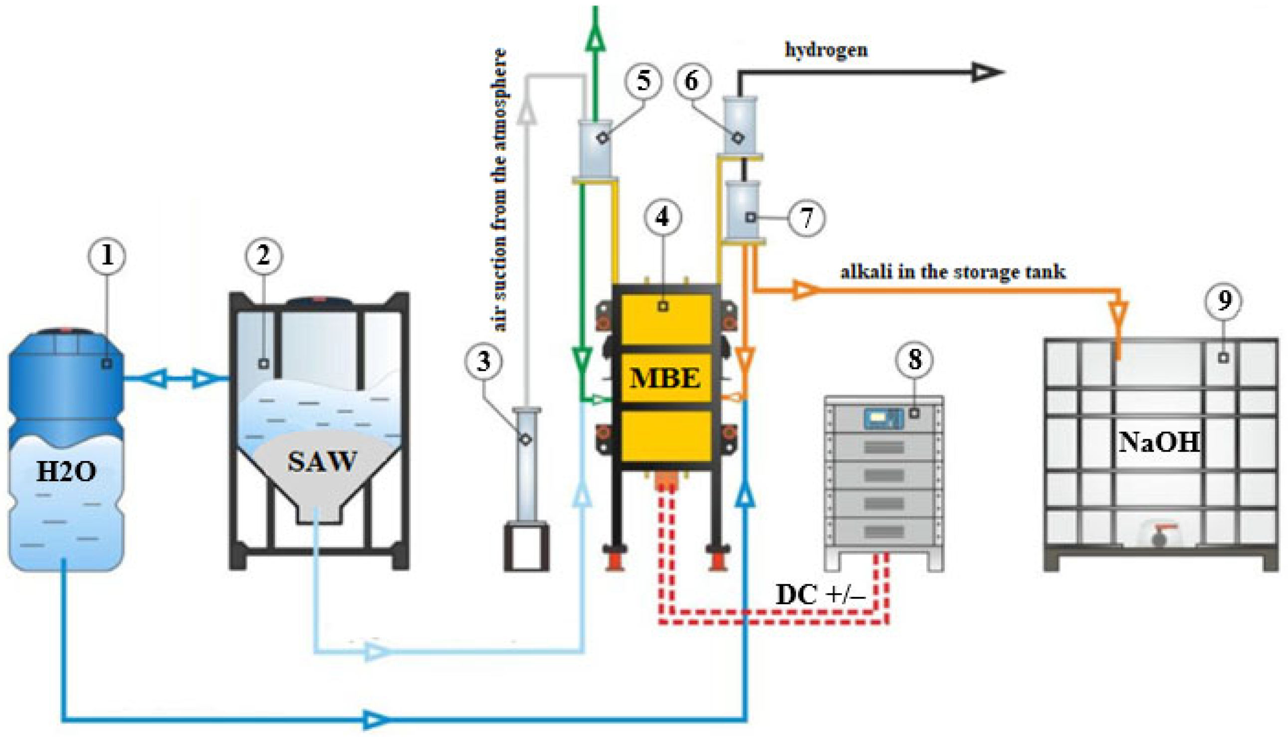
Figure 9 shows the proposed flow chart for electrochemical treatment and separation of wastewater for industrial use using bipolar electrodialysis with cation-exchange membranes.
The process is organized in a continuous or semi-continuous cycle and includes the preparation of the initial reagents, electrochemical treatment in a membrane apparatus, and separation of the target products.
The initial sulfide-alkali effluent from the production line enters storage tank 2. Simultaneously, a low-concentration alkali solution (0.02–0.05% NaOH) is fed to tank 1, which serves as a receiving solution for the cathode chambers and for the initial filling of the circuit.
From tanks 1 and 2, the solutions are pumped (not shown in the diagram) into the corresponding chambers of electrodialyzer with bipolar electrode 4. The electrodialyzer is a stack of working chambers (as shown in the diagram in
Figure 4) separated by cation-exchange membranes. Nickel plates serve as electrodes.
The odd-numbered anode chambers are filled with the initial sulfide-alkali effluent. Under the influence of an electric field from a DC source 8, sulfide ions and organic contaminants are oxidized on the surface of the nickel anodes. Sulfides are oxidized to elemental sulfur, which coagulates and precipitates.
The even-numbered cathode chambers are filled with a dilute alkali solution. A water reduction reaction occurs at the cathodes, releasing high-purity hydrogen gas. Sodium cations Na+ from the anode chambers migrate through cation-exchange membranes into the cathode chambers, where they combine with hydroxide ions OH− to form sodium hydroxide. Purified alkali solution thus accumulates in the cathode chambers.
After electrodialysis, the anolyte is removed from the electrodialyzer and sent to anolyte separator 5. Here, the solid phase (colloidal sulfur and other insoluble oxidation products) is separated from the liquid phase. Some of the sulfur-free anolyte can be returned to tank 2 (recycled), while some are discharged from the system as neutralized effluent.
Gaseous products from the anode chambers are removed through anode hydraulic seal 3, which prevents air infiltration and equalizes pressure.
The sodium hydroxide-enriched catholyte enters catholyte separator 7. Here, gaseous hydrogen is separated from the liquid phase.
Hydrogen is removed through hydrogen hydraulic seal 6, purified, and can be sent for recycling, for example, to the plant’s fuel system. The liquid catholyte (NaOH solution) after separator 7 is collected in alkali storage tank 9. The resulting commercial product is a clear solution with a concentration of 2.3–2.5% NaOH and minimal impurity content (sulfides and organics). This solution is suitable for reuse in the alkaline hydrocarbon washing process cycle, ensuring a closed water cycle and the return of valuable reagent to production.



 ,
,