


Abstract
The treatment of spent drilling fluids generated during the drilling of technological wells for uranium production represents an important engineering and environmental challenge associated with high energy consumption, significant waste generation, and the need for rational water use under arid regional conditions. Conventional phase separation methods based on gravitational settling and chemical–mechanical treatment are characterized by limited process controllability, long processing times, and increased consumption of reagents and energy. This study proposes an energy-efficient and reliable hydrodynamic technology for the treatment of spent drilling fluids based on the formation of controlled turbulent structures without the use of mechanical drives. The research object comprised spent drilling fluids (SDFs) generated during the drilling of technological wells for uranium production in the southern regions of the Republic of Kazakhstan and the Kyzylorda region. Experimental investigations were carried out using a laboratory–pilot hydrodynamic disperser with variations in velocity gradient, treatment time, flocculant dosage, and suspension flow rate. A mathematical model linking hydrodynamic process parameters with phase separation kinetics and energy characteristics was developed. Model calibration by weighted nonlinear least squares yielded a stable parameter set with 95% confidence intervals, and model validation demonstrated good agreement between calculated and experimental data (MAPE 8.4%; maximum relative error 11.8%). It was established that the use of a hydrodynamic disperser provides separation efficiency of up to 90–95% under optimal operating conditions while reducing specific energy consumption and maintaining stable repeated-cycle performance within the investigated operating window. Experimental results confirm that implementation of the hydrodynamic technology enables a reduction in sludge volume by 40–60%, recovery of up to 60–80% of process water, and a significant decrease in waste requiring transportation and disposal. The obtained results demonstrate the high environmental and resource-saving efficiency of the proposed technology and its suitability for scaling and industrial implementation at facilities drilling technological wells for uranium production. The developed hydrodynamic approach can be considered an effective engineering platform for creating energy-efficient and sustainable systems for drilling fluid treatment in regions with limited water resources and remote industrial infrastructure.
1. Introduction
In the context of the growth of industrial production and the intensification of the extraction of mineral resources, rational water use and energy-efficient treatment of process fluids are becoming key tasks of engineering ecology and energy-oriented technological systems [1,2,3]. The high energy intensity of treatment processes, as well as the limited capabilities of existing technologies for fractionation of dispersed systems, leads to significant losses of water and energy and the formation of hard-to-dispose-of waste [4,5]. Within the framework of modern concepts of sustainable development and closed production cycles, the development of energy-efficient methods for the separation of multicomponent suspensions with the return of water to technological circulation is of particular importance [6].
This problem is especially acute in the drilling and mining industries, where significant volumes of liquid waste are generated directly during technological operations and require prompt treatment. Spent drilling fluids are complex highly concentrated dispersed systems characterized by a wide particle size distribution of the solid phase and the presence of chemical reagents used to regulate rheological and filtration properties [7]. In the absence of effective separation technologies, such systems are accumulated in sludge collectors or transported to landfills, which is accompanied by increased energy costs, environmental risks, and loss of potentially reusable industrial water [8].
The urgency of this task is especially high for regions of uranium production with limited water resources and increased environmental sensitivity. Areas with intensive drilling of technological wells for uranium production are characterized by significant volumes of drilling waste with the simultaneous tightening of requirements for reducing water consumption, reducing the volume of cuttings, and increasing the energy efficiency of technological processes [9]. Under these conditions, there is a growing need for compact, reliable, and energy-efficient technologies for local treatment of drilling fluids with the ability to return water directly to the production cycle [10].
Conventionally, spent drilling fluids are treated using gravity sedimentation and mechanical mixing with the addition of coagulants and flocculants, centrifugation, and hydrocyclone separation [11]. However, these approaches have significant limitations. Gravity sedimentation is characterized by a low purification rate, a long residence time, and large space requirements. Mechanical mixing with chemical treatment can improve separation efficiency, but is associated with high specific energy consumption, increased reagent demand, and reduced process stability. Centrifugal and hydrocyclone methods provide relatively rapid phase separation, but they are limited by equipment complexity, increased wear, and reduced applicability to highly concentrated abrasive suspensions [12]. These shortcomings create the need for alternative hydrodynamic technologies capable of combining high separation efficiency with lower energy demand and higher operational stability.
Against the background of these limitations, hydrodynamic treatment methods based on the controlled formation of turbulent zones and shear stresses in the flow without the use of mechanical drives are of increasing interest. More broadly, hybrid validation strategies that combine experimental or field observations with analytical, numerical, reliability-based, or data-driven models are widely used in energy extraction to improve the credibility of process evaluation and operating-mode selection. Representative recent examples include fracturing-effectiveness assessment through flowback data and pressure-transient interpretation, field-data-based comparison of drag-reduction methods using the AHP and reliability analysis models, and machine learning-assisted screening of enhanced oil recovery methods under domain-informed constraints [13,14,15,16]. In this context, experimental and numerical studies show that such hydrodynamic effects make it possible to intensify the processes of aggregation and fractionation of the solid phase, increasing the degree of separation while reducing specific energy consumption. However, many existing hydrodynamic solutions remain structurally complex, require moving elements, or do not provide stability of characteristics during long-term operation, which limits their industrial applicability [17,18].
A promising direction is the use of hydrodynamic devices, in which high-energy turbulent structures are formed due to the kinetic energy of the flow at a relatively small pressure drop. The combination of jet–vortex actions with controlled flocculation processes makes it possible to realize a synergistic effect consisting of increasing the efficiency of phase separation, reducing the consumption of reagents, and reducing the time of sedimentation [16]. At the same time, the issues of optimizing the design of such devices, determining energy-efficient operating modes, and developing generalized models that link hydrodynamic parameters with energy consumption and process kinetics [17] remain insufficiently studied.
In this regard, the purpose of this work is to develop and experimentally substantiate an energy-efficient and reliable hydrodynamic technology for separating spent drilling fluids into liquid and solid phases with the subsequent return of water to the production cycle [18]. As part of the study, the analysis of the influence of hydrodynamic and chemical parameters on the efficiency of phase separation was carried out, a mathematical model of the process was developed and validated, and the energy efficiency, stability, and reproducibility of technological characteristics under repeated operating cycles were assessed.
The scientific novelty of the work lies in the comprehensive assessment of the hydrodynamic technology, including a joint analysis of the separation efficiency, energy characteristics, and operational reliability of the process [19]. For the first time for this class of hydrodynamic devices, a model linking the velocity gradient, pressure drop, and processing time with fractionation kinetics and specific energy costs was proposed and experimentally confirmed, and a pronounced synergistic effect of joint hydrodynamic and chemical action was shown [20].
The article is organized as follows. Section 2 presents the materials, experimental setup, research methods, and mathematical model of the process. Section 3 describes the experimental conditions, the algorithmic workflow of the experimental–model procedure, and the methods of data processing. Section 4 provides analysis and discussion of the results, including evaluation of separation efficiency, energy efficiency, model validation, and process sustainability analysis. Section 5 examines the industrial applicability, scaling, and economic feasibility of the proposed technology, and Section 6 formulates the main findings and directions for further research.
2. Materials and Methods
2.1. Objects of Research and Conditions of Sampling
The object of the study was spent drilling fluids generated during the drilling of technological wells for uranium production in the southern regions of the Republic of Kazakhstan and the Kyzylorda region. These regions are characterized by the intensive development of uranium production and significant volumes of technological well drilling, significant volumes of circulating drilling fluids, and increased requirements for resource conservation due to the shortage of fresh water and the remoteness of drilling sites [21].
Sampling of spent drilling fluids was carried out directly at technological well drilling sites used for uranium production after the completion of the active phase of drilling, before their disposal or storage. Samples were taken in accordance with the requirements of the ISO 3170 standard for industrial liquid sampling, which ensured the representativeness of the composition and the reproducibility of the results. To avoid delamination and secondary changes in the structure of the suspension, the samples were transported and stored in sealed containers at ambient temperature [22].
Spent drilling fluids were considered as complex multicomponent dispersed systems, including an aqueous phase, finely dispersed particles of drilled rock, clay minerals, and residual reagents [23] used to regulate the rheological and filtration properties of drilling fluids. The high concentration of the solid phase and the wide particle size distribution determine the stability of such systems and their tendency to reach a long-term suspended state [24].
2.2. Physical and Chemical Characteristics of Spent Drilling Fluids
The mass fraction of the solid phase was measured gravimetrically, the density was measured by the pycnometric method, the viscosity was measured using a rotary viscometer, the pH index was potentiometric, and the particle size distribution was measured by laser diffraction. Table 1 shows the characteristics of spent drilling fluids from technological wells for uranium production in southern Kazakhstan and the Kyzylorda region.
Table 1.
Physical and chemical characteristics of spent drilling fluids (Southern Kazakhstan, Kyzylorda region).
The data obtained indicate a high dispersion of the solid phase and a moderate viscosity of the suspension, which creates unfavorable conditions for gravitational deposition. The presence of particles smaller than 20 μm determines the stability of the suspension and the need for intensive hydrodynamic actions for effective phase separation.
2.3. Design and Principle of Operation of a Hydrodynamic Dispersant
For the treatment of spent drilling fluids (SDFs), a developed cylindrical hydrodynamic disperser of a cylindrical type was used, designed to form controlled turbulent structures in the flow without the use of mechanical drives.
Structurally, the device is a vertical cylindrical body made of corrosion-resistant steel and equipped with inlet and outlet nozzles. Inside the body, three cascades of active elements are arranged along the height, each comprising perforated discs with combined hole geometry and freely moving steel balls with a diameter of 6 mm. The holes in the perforated discs are inclined at 20–30° to the flow axis, which promotes jet swirling and the formation of stable vortex zones. Center holes provide axial mass transfer and hydraulic stabilization. The cascade arrangement of elements allows us to gradually increase the turbulent effect and evenly distribute energy throughout the entire working volume of the device.
The principle of operation of the dispersant is based on a combination of the following mechanisms:
- Shear stresses that occur when the flow passes through the holes of the disks.
- Turbulent vortices formed by swirling jets.
- Local pressure impulses arising from collisions of balls with each other and with the walls of the body.
This combination provides intensive dispersion, the destruction of weak aggregates, and the simultaneous creation of conditions for the controlled aggregation of particles in the presence of flocculant.
2.4. Experimental Setup and Research Methods
In order to ensure the reproducibility of the experimental results and to have a clear understanding of the hydrodynamic and energetic interactions occurring during treatment, a detailed schematic model of the laboratory experimental setup was developed as shown in Figure 1. The diagram illustrates the main process units, measurement points, and hydrodynamic disperser as the key element responsible for turbulence generation and phase separation.
Figure 1.
Schematic diagram of the experimental setup for hydrodynamic treatment of spent drilling fluids, including the feed tank, pre-mixing agitator, flocculant dosing unit, centrifugal pump, flow meter, inlet and outlet pressure sensors, hydrodynamic disperser, sedimentation tank, and clarified water outlet with sludge collection unit, with an enlarged inset showing the internal structure of the disperser, including inclined perforated discs, swirling jets, turbulence zones, and ball–wall collision regions, while the key geometric parameters of the active elements, including the 6 mm moving balls and the 20–30° hole inclination, are specified in Section 2.3.
Figure 1 summarizes the main units of the laboratory setup, the measurement points, and the internal configuration of the hydrodynamic disperser. To avoid overloading the schematic, the detailed geometric characteristics of the active elements are not repeated in the figure itself. The principal design parameters relevant for reproducibility are given in Section 2.3, including the diameter of the freely moving balls (6 mm) and the inclination angle of the perforated-disc holes (20–30° to the flow axis).
The experimental rig operated in a closed loop and was designed to simulate the conditions of the local treatment of drilling fluids. The spent drilling fluid was continuously homogenized before treatment, after which a flocculant was injected into the stream as needed. Hydraulic power was supplied by a centrifugal pump, and the flow rate and pressure drop on the hydrodynamic disperser were monitored in real time.
Hydrodynamic treatment was carried out in a developed disperser that forms intense turbulent zones due to cascading perforated discs and movable ball elements. After treatment, the slurry was sent to a sedimentation tank to separate clarified water and compacted sludge. The OBR suspension was pre-homogenized, after which it was fed into the dispersant. During the experiments, the main technological parameters varied:
- -
- Velocity gradient G = 500–1500 s−1;
- -
- Processing time τ = 60–180 s;
- -
- Flocculant dosage Dfl = 0–100 g/t.
After treatment, samples were taken to determine the residual concentration of the solid phase and to assess the rate and density of sedimentation.
2.5. Mathematical Model of Energy Efficiency of the Process
To quantitatively describe the process of spent drilling fluid treatment, a mathematical model has been developed that relates the hydrodynamic parameters of the dispersant operation with the energy and technological characteristics of the process.
2.5.1. Power Balance
The hydrodynamic power supplied to the system is determined by the expression:
where
- is the pressure drop in the dispersant, Pa;
- is the volume flow rate of the suspension, m3/s.
The dissipative power component associated with turbulent vortices is defined as:
where
- is the dynamic viscosity of the suspension, Pa·s;
- is the average velocity gradient, s−1;
- is the dispersant displacement, m3;
- is the empirical energy-transfer coefficient k, determined by model calibration (Table 2).Table 2. Calibrated empirical parameters of the mathematical model, 95% confidence intervals, and normalized sensitivity coefficients.
2.5.2. Total Energy Consumption
The total energy expenditure during treatment τ is calculated as:
2.5.3. Kinetics of Phase Separation
The change in the concentration of the solid phase is described by the kinetic equation:
where
- is the solid-phase concentration, kg/m3;
- is the flocculation rate constant;
- α.β are empirical indicators;
- is the energy of activation of the process;
- R is the universal gas constant;
- T is the temperature, K.
2.5.4. Energy Efficiency Criterion
The energy efficiency criterion was used as an integral indicator:
where is the volume of allocated technical water.
Model calibration was performed using weighted nonlinear least squares based on the simultaneous fitting of separation efficiency and specific energy consumption. The objective function was defined as
where and are the experimental and calculated separation efficiencies for the i-th operating condition, and are the corresponding experimental and calculated specific energy consumption, and and are the standard deviations obtained from triplicate measurements. Parameter confidence intervals were estimated by bootstrap resampling (1000 iterations), and parameter sensitivity was evaluated using normalized local sensitivity coefficients.
2.6. Model Validation
The model and its computational implementation were validated against experimental data on separation efficiency and specific energy consumption. The numerical tool used in the study represents a direct software implementation of Equations (1)–(5). Validation was performed in three stages: analytical verification of the implemented equations and dimensional consistency of the calculated variables; comparison of software-generated outputs with independent hand calculations for representative operating conditions; and comparison of model predictions with laboratory–pilot experimental data. Residuals were evaluated using both conventional and robust diagnostics, including the maximum relative error, median absolute error, MAD-based scale estimates, and bootstrap confidence intervals for residual location. To provide a more transparent error analysis, the total prediction error was interpreted as the sum of a systematic component and a random component: the systematic component was assessed through the signed residual bias and the presence or absence of residual trends with respect to the velocity gradient and processing time, whereas the random component was characterized by the dispersion of residuals around zero using the RMSE, MAD-based scale estimates, and bootstrap uncertainty intervals. The model was considered adequate within the investigated operating window when the signed residual location remained close to zero and no systematic residual trend was observed. Using the calibrated parameter set presented in Table 2, the model yielded RMSE = 3.8 percentage points for separation efficiency, MAPE = 8.4%, and a maximum relative error of 11.8%. The discrepancy between software outputs and reference analytical calculations was negligible within numerical precision, while the remaining experimental–model mismatch was dominated by bounded random scatter rather than by a systematic model bias. This agreement supports the use of the model for operating-mode optimization, sensitivity analysis, and process scale-up.
3. Experimental Procedure and Data Processing
This section describes the methodology for conducting the experimental studies, the algorithmic sequence of the experimental–model procedure, and the approaches used for processing and analyzing the experimental data in order to assess the efficiency, energy performance, and stability of the hydrodynamic separation process for spent drilling fluids.
3.1. Experimental Conditions and Test Matrix
Experimental studies were carried out on a laboratory–pilot plant of a hydrodynamic dispersant, the description of the design and principle of operation of which is given in Section 2. As an object of study, spent drilling fluids were obtained from technological well drilling sites for uranium production typical for the southern regions of the Republic of Kazakhstan, and previously reduced to reproducible initial parameters for the concentration of the solid phase and rheological characteristics [25].
The experiment program was designed to cover a wide range of operating parameters and to allow for the analysis of both individual factors and their combined influence on process characteristics. In the course of the studies, the following parameters varied:
- -
- The velocity gradient G, which determines the intensity of hydrodynamic action;
- -
- The processing time τ;
- -
- The flocculant dosage;
- -
- The flow rate of the slurry to be treated and the corresponding pressure drop.
The ranges of parameter changes were selected on the basis of preliminary tests and analysis of literature data, taking into account the stable operation of the facility and the prevention of cavitation and erosion effects.
3.2. Experimental Procedure
Each experimental cycle included successive stages of sample preparation, hydrodynamic treatment, measurement, and data analysis. To make this procedure explicit and reproducible, the overall experimental–model workflow is summarized in Algorithm 1. The initial drilling fluid was fed into the system at a given flow rate, after which a flocculant with a controlled dosage was introduced into the stream if necessary. The treatment was carried out in a continuous mode at fixed values of hydrodynamic parameters for a given time.
At the end of the treatment, samples were taken at the outlet of the plant and analyzed to determine the concentration of the solid phase, turbidity, and sedimentation rate. To assess reproducibility, each operating condition was independently repeated three times (n = 3), after which the mean values, standard deviations (SDs), and 95% confidence intervals (CIs) were calculated. Statistical significance between operating conditions was evaluated by one-way ANOVA followed by Tukey’s post hoc test, with p < 0.05 considered significant [26].
| Algorithm 1. Experimental–model workflow for hydrodynamic treatment of spent drilling fluids. |
| Step 1. Prepare and homogenize the spent drilling fluid sample with controlled initial solid-phase concentration and rheological characteristics. Step 2. Set the operating parameters of the experiment, including slurry flow rate, velocity gradient G, treatment time τ, and flocculant dosage Dfl. Step 3. Feed the suspension into the laboratory setup and perform hydrodynamic treatment in the disperser under the selected operating conditions. Step 4. Measure the hydraulic parameters during treatment, including flow rate Q and pressure drop ΔP across the hydrodynamic disperser. Step 5. Collect treated samples at the outlet and determine residual solid-phase concentration, turbidity, sedimentation rate, and sediment characteristics. Step 6. Calculate phase separation efficiency and specific energy consumption using Equations (6) and (7) and the relations given in Section 2.5. Step 7. Repeat the experiment at least three times for each operating condition and determine the mean values and uncertainty measures. Step 8. Compare the experimental results with the mathematical-model predictions and identify the operating window that provides the best combination of separation efficiency and energy performance. Step 9. Perform repeated-cycle tests under optimal conditions to assess process stability, repeatability, and operational reliability. |
Particular attention was paid to the stability of the facility and the absence of degradation of characteristics during the experiments. For this purpose, a series of repeated tests were carried out under optimal conditions, during which the main hydrodynamic parameters, including pressure drop and flow, were monitored.
3.3. Evaluation of Separation Efficiency and Sedimentation Kinetics
The efficiency of phase separation was evaluated by reducing the concentration of the solid phase in the liquid part of the suspension after treatment. As an integral indicator, the efficiency of η separation was used, defined as:
where are the concentrations of the solid phase in the input and output samples, respectively.
The kinetics of sedimentation were analyzed based on the measurement of the sedimentation rate of aggregates under static conditions after hydrodynamic treatment. This parameter was used to assess the effect of hydrodynamic and chemical effects on the formation of stable flocculae and their sedimentary properties [27].
3.4. Energy Consumption and Specific Energy Calculation
The energy performance of the process was evaluated based on measurements of the pressure drop and slurry flow. The hydraulic power supplied to the unit was calculated by the expression:
where is the pressure drop across the hydrodynamic dispersant, and is the volumetric flow rate of the suspension.
The specific energy consumption was defined as the ratio of the energy consumed to the volume of the treated suspension, taking into account the processing time. This approach made it possible to correctly compare the energy characteristics of the proposed technology with traditional processing methods.
3.5. Reliability and Repeatability Assessment
To assess operational reliability and process stability [28], repeated experiments were carried out at fixed optimal parameters. Let yc denote the observed response in cycle c, where yc may represent the separation efficiency, pressure drop, or specific energy consumption. The repeated-cycle data were analyzed using the decomposition yc = θ + b·c + εc, where θ is the stationary level, b is the trend parameter, and εc is the stochastic deviation.
Stable operation was assessed using a distribution-agnostic criterion based on three indicators: the absence of a statistically significant monotonic trend, evaluated by the Theil–Sen slope estimator and the Mann–Kendall test; bounded robust dispersion, evaluated by the median absolute deviation, ; and the absence of systematic drift in the hydraulic parameters over repeated cycles. This approach makes it possible to assess process stability without relying solely on mean-based statistics or a normality assumption, which is important for concentrated heterogeneous suspensions with potentially skewed or heavy-tailed deviations [29].
3.6. Data Processing and Uncertainty Analysis
The processing of experimental data was carried out using standard methods of statistical analysis. For each mode, averages, standard deviations, and confidence intervals were calculated. Measurement errors were taken into account when comparing experimental and calculated data and when validating the mathematical model [30]. In addition, the computational implementation of the model was checked by independent benchmark calculations for representative operating modes to verify the correctness of the numerical realization of Equations (1)–(5).
For model validation, residuals were defined as . Their quality was assessed using both conventional and robust criteria, including the relative error, median absolute error, median absolute percentage error, and MAD-based scale estimates. In the revised error analysis, the total model discrepancy was decomposed into a systematic component and a random component. The systematic component was evaluated using the mean signed residual and by checking for residual trends versus velocity gradient and processing time, whereas the random component was evaluated through the dispersion of residuals around the zero-bias level using the RMSE, MAD-based scale estimates, and bootstrap confidence intervals. Accordingly, the conclusions on reproducibility and robustness were based not only on average deviations, but also on the absence of systematic residual bias and on bounded robust dispersion in the investigated operating window. For each operating mode, the results are reported as mean ± SD for n = 3 independent replicates, and 95% confidence intervals were calculated using the Student t distribution. The statistical significance of differences between groups was assessed by one-way ANOVA with Tukey’s post hoc correction, with p < 0.05 considered significant. Measurement uncertainty was propagated into the model-validation procedure through the weighting terms of the fitting objective function. Comparison of the experimental and calculated values was then used to quantify model accuracy and define the applicability range of the developed model.
4. Results and Discussion
4.1. Hydrodynamic Separation Efficiency
The results of experimental studies have shown that the efficiency of the hydrodynamic separation of spent drilling fluids in the developed disperser is primarily determined by the value of the flow velocity gradient G and the hydrodynamic treatment time τ for aggregation of the solid phase.
At low values of the velocity gradient (G < 700 s−1), the hydrodynamic action turned out to be insufficient for the effective destruction of stable finely dispersed aggregates. Under these conditions, the separation process proceeded unsteadily, an increased concentration of suspended particles remained in the clarified liquid, and sedimentation was characterized by a low rate and low sediment density.
An increase in the velocity gradient to the range of 1100–1300 s−1 led to a sharp increase in the efficiency of phase separation. In this interval, stable turbulent structures were formed, providing intensive mixing and a high frequency of interparticle collisions. It was experimentally established that, at the specified values of G, the residual concentration of the solid phase in the purified liquid decreased to 110–130 mg/L, and the overall separation efficiency reached 90–95%. The results were reproduced for various compositions of spent drilling fluids and are consistent with the data of both series of studies used in the work.
The effect of the treatment time τ was pronounced and nonlinear. With a duration of exposure less than 60–90 s, the process did not have time to reach a stationary mode, and the formed units had insufficient stability. Increasing the treatment time to 120–150 s ensured the stabilization of the process and the achievement of the maximum degree of phase separation; it did not lead to a proportional increase in efficiency and was accompanied by an increase in energy consumption, which indicates the presence of an optimal interval of modes [31].
The introduction of flocculant had a significant impact on the efficiency of the process. In the absence of the reactant, the maximum degree of separation did not exceed 80–85% even at high velocity gradient values, which is associated with the stabilization of finely dispersed particles in the turbulent flow [32]. The addition of flocculant led to an acceleration of the aggregation and sedimentation processes, while the optimal dosage was set at the level of about 50 g/t. Under these conditions, the separation efficiency reached 93–95%, and the formed sludge was characterized by increased density and stability. Exceeding this dosage did not provide a further improvement in results and in some cases was accompanied by deterioration of characteristics due to oversizing and partial destruction of flocculae.
Two-dimensional visualization of experimental data was used to identify optimal hydrodynamic modes [33] and visualize the combined effect of the velocity gradient and processing time on the separation efficiency. Figure 2 shows a map of the distribution of hydrodynamic separation efficiency in velocity-to-treatment time coordinates, based on the average results of a series of experiments.
Figure 2.
Effect of velocity gradient and processing time on the hydrodynamic separation efficiency of spent drilling fluids, shown as a contour map in the coordinates of velocity gradient G (s−1) and processing time τ (s) based on mean values from triplicate experiments, with experimental operating points annotated as mean ± SD (n = 3) and the identified optimal operating window at G = 1100–1300 s−1 and τ = 120–150 s, where the highest separation efficiency was achieved with acceptable specific energy consumption.
Figure 2 shows the distribution of separation efficiency in the G–τ coordinate space, where G is the velocity gradient (s−1) and τ is the processing time (s). The contour intervals correspond to the mean efficiency values obtained from triplicate experiments, and the plotted experimental points indicate the actual operating modes used in the study. The figure makes it possible to directly identify the optimal operating window at G = 1100–1300 s−1 and τ = 120–150 s, where the separation efficiency reaches 93–95% while maintaining energy-efficient operation. At lower G values, the hydrodynamic action is insufficient even with increasing τ, whereas excessive intensification outside the optimum mainly increases energy consumption without proportional technological benefit.
This visualization confirms the key role of the velocity gradient as a control parameter of aggregate fracture kinetics and flocculation processes [34], which is consistent with the mathematical model presented in Section 2.5. From a practical point of view, Figure 2 provides an engineering tool for selecting the optimal operating modes of the hydrodynamic disperser, explicitly defining the recommended window as G = 1100–1300 s−1 and τ = 120–150 s for subsequent scale-up and adaptation to different operating conditions [35].
Chemical intensification of phase separation processes is an important element in the treatment of spent drilling fluids, but excessive use of reagents can lead to an increase in operating costs and a deterioration in the stability of the process [36]. In this regard, a quantitative analysis of the effect of flocculant dosage not only on the final separation efficiency but also on the kinetics of sedimentation is necessary. To assess the effect of flocculant dosage on the characteristics of the hydrodynamic separation process, a series of experiments were carried out under fixed hydrodynamic conditions and variable reagent flow. Figure 3 presents the results of these studies as a function of separation efficiency and sedimentation rate as a function of flocculant dosage. The use of combined visualization with two ordinate axes makes it possible to simultaneously assess the influence of the chemical factor on both the degree of purification [37] and the dynamics of sludge formation [38].
Figure 3.
Effect of flocculant dosage on separation efficiency and sedimentation rate during hydrodynamic treatment of spent drilling fluids, where symbols represent mean values, error bars indicate ±SD (n = 3), and different letters above the separation efficiency points denote statistically significant differences between dosage levels according to one-way ANOVA followed by Tukey’s post hoc test (p < 0.05).
Figure 3 shows the dependence of separation efficiency and sedimentation rate on flocculant dosage. The abscissa axis represents the reagent dosage (g/t), the left ordinate axis shows the separation efficiency (%), and the right ordinate axis shows the sedimentation rate. The plotted values correspond to mean ± SD for three independent experiments, and the statistical significance of differences between dosage levels was evaluated by one-way ANOVA with Tukey’s post hoc test.
The graph demonstrates a pronounced optimum in flocculant dosage near 50 g/t, at which both separation efficiency and sedimentation rate reach their maximum values. One-way ANOVA followed by Tukey’s post hoc test confirmed that the increase in separation efficiency at the optimum dosage is statistically significant relative to the low-dosage conditions (p < 0.05). At dosages below this level, the flocculant effect is insufficient for the formation of stable aggregates, whereas exceeding the optimum does not produce further statistically meaningful improvement and indicates saturation of the flocculation effect. Figure 3 therefore confirms that the role of the flocculant in the proposed technology is not to replace hydrodynamic action, but to enhance it within a limited optimal dosage range. The presence of a clear optimal dosage indicates the synergistic nature of the interaction of chemical and hydrodynamic mechanisms [39], in which the maximum technological effect is achieved with the minimum consumption of the reagent. From a scientific point of view, this graph illustrates the nonlinear kinetics of particle aggregation under conditions of intense turbulence. From a practical point of view, Figure 3 provides an engineering rationale for choosing the optimal flocculant dosage and minimizes operating costs in the industrial implementation of the technology.
4.2. Formation and Dynamics of Turbulent Structures
The high efficiency of hydrodynamic separation [40] achieved in the course of experiments is due to the peculiarities of the formation and dynamics of turbulent structures in the volume of the developed dispersant. The passage of the suspension through perforated disks with inclined holes leads to the formation of swirling jets that initiate a complex three-dimensional vortex movement of the flow. Such vortex structures create an alternation of zones of high and moderate shear stresses, which leads to, on the one hand, the destruction of weak primary aggregates, and on the other hand, the conditions for controlled aggregation of particles at subsequent stages. In contrast to the once-through hydrodynamic schemes implemented in a number of traditional devices, in this case, a uniform distribution of energy over the entire working volume is ensured, which excludes the formation of stagnant zones [41]. A ball nozzle plays a special role in the dispersion and fractionation mechanism. The free movement of steel balls under the influence of a swirling flow is accompanied by their periodic collisions with each other and with the inner surface of the body. These collisions create local pressure pulses and short-term zones of increased energy dissipation [42], which contribute to the destruction of stable aggregates and the activation of aggregation processes. Thus, some of the balls actually perform the function of working fluids, similar to the elements of drum ball mills, but without the supply of additional mechanical energy.
The combined action of jet–vortex flows and contact interactions ensures a more complete use of the kinetic energy of the fluid flow and explains the high dispersion efficiency at a relatively small pressure drop. It is this synergistic effect that is the key difference between the developed device and traditional hydrodynamic and mechanical systems.
The experimentally revealed optimal modes of hydrodynamic separation require a physical explanation from the point of view of the mechanisms of energy and mass transfer within the apparatus. One of the key features of the developed dispersant is the formation of complex turbulent structures that provide an intense but controlled effect on the dispersed system. To illustrate these mechanisms, a schematic representation of the flow structure inside the disperser is used. For a visual analysis of the processes occurring inside the hydrodynamic dispersant, a structural scheme of the formation of turbulent flows and energy dissipation zones was developed. Figure 4 demonstrates the main elements of the internal fluid dynamics of the apparatus, including swirling jets, zones of increased shear stresses, and regions of local impulse action that occur when spherical elements interact with flow and housing. This visualization makes it possible to connect the design features of the dispersant with the formation of controlled turbulent structures and explain the high efficiency of phase separation obtained in optimal modes [43].
Figure 4.
Schematic representation of turbulent structure formation inside the hydrodynamic disperser, highlighting swirling jets generated by inclined perforated discs, high-shear zones, and ball–wall collision regions as the main mechanisms governing energy redistribution and phase separation.
Figure 4 schematically shows the internal flow structure of a hydrodynamic disperser in the operating mode. The swirling jets formed as the suspension passes through the inclined holes of the perforated discs create stable vortex structures and areas of intense mixing. These zones are characterized by increased values of the velocity gradient and ensure the destruction of weak solid-phase aggregates. Freely moving spherical elements are involved in vortex motion and periodically collide with each other and with the walls of the body. The resulting local pressure pulses and short-term zones of high energy dissipation increase turbulence without increasing overall energy consumption. The cascade arrangement of active elements provides a step-by-step redistribution of energy along the height of the apparatus and prevents the formation of stagnant zones [44].
Figure 4 makes it possible to visually link the design features of a hydrodynamic dispersant with the physical mechanisms of turbulent structure formation. Visualization emphasizes the role of inclined holes in creating swirling jets that provide a stable vortex movement and uniform distribution of energy over the working volume of the device. From a scientific point of view, the figure confirms that the combination of jet–vortex flows and local contact interactions forms a multi-level turbulence structure that is optimal for the processes of aggregate destruction and subsequent controlled aggregation. From an engineering point of view, Figure 4 demonstrates why an increase in separation efficiency is achieved without a proportional increase in energy costs, and thereby justifies the advantages of the proposed hydrodynamic scheme in comparison with traditional mechanical mixing systems [45].
4.3. Validation of the Mathematical Model
To confirm the adequacy of the developed mathematical model, validation was carried out using the calibrated parameter set reported in Table 2. The comparison of model-predicted and experimental values of separation efficiency and specific energy consumption over the investigated operating range showed good agreement, with RMSE = 3.8 percentage points, MAPE = 8.4%, and a maximum relative error of 11.8%. The error analysis further showed that the systematic component of the discrepancy was small, since the signed residuals remained centered near zero and no residual trend with respect to velocity gradient or processing time was detected, whereas the remaining mismatch was associated mainly with bounded random scatter of the experimental–model residuals.
In the optimal operating window (G = 1100–1300 s−1, τ = 120–150 s), the discrepancy between calculated and experimental values remained within the 95% confidence intervals of the triplicate measurements, confirming the predictive capability of the model under practically relevant conditions.
Such a hybrid validation framework, combining experimental observations with model-based interpretation, is consistent with current practice in energy extraction, where field and laboratory data are increasingly analyzed jointly with analytical, reliability-based, or machine-learning models to evaluate process effectiveness and support engineering decisions [14,15,16]. A comparison of the dependencies of phase separation efficiency and specific energy consumption on the velocity gradient and processing time showed good convergence of results.
To verify the correctness of the mathematical model presented in Section 2.5, the experimentally measured efficiency of phase separation was compared with the calculated values obtained on the basis of model equations. Figure 5 presents the results of this comparison in the form of a correlation graph that allows us to visually assess the degree of correspondence between experimental and theoretical data.
Figure 5.
Comparison between experimentally measured and model-predicted separation efficiency under different hydrodynamic operating conditions, where the dashed line indicates ideal agreement between experimental and calculated values.
The diagonal line on the graph corresponds to the perfect coincidence of the calculated and experimental values, and the deviations of the experimental points from this line characterize the value of the model error.
Figure 5 shows the dependence of the experimentally measured hydrodynamic separation efficiency on the values predicted by the mathematical model. The abscissa axis shows the calculated efficiency values obtained at various combinations of the speed gradient and processing time, and the ordinate axis shows the corresponding experimental data.
The distribution of points near the equality line indicates good agreement between the experiment and the model. In the revised analysis, this conclusion is supported not only by visual inspection, but also by robust residual diagnostics, including median-based error measures and bootstrap uncertainty intervals. The absence of systematic residual bias across the investigated ranges of velocity gradient and processing time indicates that the main physical mechanisms of the process are described correctly [46].
Figure 5 clearly confirms the adequacy of the developed mathematical model and its ability to reproduce experimental data across a wide range of operating parameters. The concentration of experimental points near the line of perfect coincidence indicates that the model correctly takes into account the influence of key control factors, primarily the velocity gradient and processing time. From a scientific point of view, this graph confirms the physical validity of the model assumptions made and the applicability of the model for the analysis of hydrodynamic fractionation processes. From a practical point of view, Figure 5 demonstrates the ability to use the model to predict separation efficiency and select the optimal disperser modes when scaling up the technology.
The validation results confirm that the proposed model adequately describes the main patterns of the process and can be used to predict efficiency and energy consumption when changing operating modes, as well as to scale up the technology [47].
4.4. Energy Efficiency Assessment
Energy efficiency is one of the key criteria for evaluating technologies for the disposal and processing of used drilling fluids, since these processes are usually characterized by high energy intensity and significant operating costs. In traditional processing schemes, the main part of the input energy is spent on the operation of mechanical drives and uncontrolled mixing, while only a limited part of the energy is directly involved in the processes of aggregate destruction and phase separation. This leads to a disproportionate increase in energy consumption when trying to intensify the process and significantly limits the possibilities of optimization [48].
In the proposed technology, a fundamentally different approach to the use of energy consists of the rejection of mechanical drives and the purposeful conversion of the hydraulic energy of the flow into useful hydrodynamic actions. The energy supplied by the pump is used to form controlled turbulent structures, high velocity gradients, and local pressure pulses, which are directly involved in the mechanisms of dispersion, aggregation, and accelerated sedimentation. This approach allows us to consider the process not only from the point of view of absolute energy consumption, but also from the point of view of the efficiency of energy conversion into a technological effect [49].
To quantify and physically interpret the energy transformations in the system, a mathematical model was developed in Section 2.5 that relates the pressure drop, slurry flow rate, and velocity gradient to the specific energy expenditure and phase separation efficiency. However, equations alone are not enough to visualize the mechanisms of energy redistribution within the apparatus. In this regard, it is advisable to use a conceptual diagram of energy flows, which makes it possible to visually reflect the energy balance of the process and explain the experimentally observed decrease in specific energy consumption. The resulting energy-flow diagram is shown in Figure 6.
Figure 6.
Energy-flow diagram illustrating the transformation of hydraulic energy supplied by the pump into useful separation work within the hydrodynamic disperser, where blue denotes the input hydraulic energy supplied by the pump, orange denotes the useful redistribution of energy into turbulent and shear actions contributing to phase separation, and gray and red denote viscous dissipation and secondary hydraulic losses.
The energy-flow diagram shown in Figure 6 illustrates the physical nature of the energy transformations underlying the operation of a hydrodynamic dispersant. According to the energy balance equations, the input energy is determined by the pressure drop and slurry flow rate and is supplied to the apparatus in the form of hydraulic power. Inside the dispersant, this energy is not spent on rotation or friction of mechanical elements, but is redistributed between turbulent, shear, and contact mechanisms of impact on the dispersed system.
The diagram clearly shows that a key part of the input energy is converted into intense turbulent flows and zones of increased shear stresses formed by swirling jets and collisions of spherical elements. It is these mechanisms that determine the value of the velocity gradient, which, according to the mathematical model, is the main control parameter of the kinetics of the destruction of aggregates and flocculation processes. Thus, Figure 6 graphically relates the energy characteristics of the process to the kinetic equation of phase separation and confirms the physical validity of the chosen model approach.
An important result reflected in the diagram is the differentiation of useful and non-useful parts of the energy balance. Viscous dissipation and secondary hydraulic losses, presented in the lower part of Figure 6, do not dominate the energy mix, which explains the achievement of a high degree of phase separation without a proportional increase in energy consumption. In comparison with traditional technologies, in which a significant part of the energy is lost in mechanical drives and uncontrolled mixing, the proposed hydrodynamic scheme provides a higher efficiency of the input energy [50].
The color coding in Figure 6 is used to represent the structure of the process energy balance in a visually explicit form. The blue elements denote the input hydraulic energy supplied by the pump and defined by the pressure drop and slurry flow rate according to Equation (1). The orange elements denote the useful redistribution of this input energy into turbulent and shear actions inside the hydrodynamic disperser, which govern the formation of the velocity gradient G and directly contribute to aggregate destruction, controlled flocculation, and phase separation. The gray and red elements denote non-useful energy expenditure associated with viscous dissipation and secondary hydraulic losses. This color structure provides a direct visual link between the energy balance equations, the phase separation kinetics, and the physical mechanisms of energy redistribution within the apparatus.
From a scientific point of view, Figure 6 acts as a link between the mathematical model and the experimental results, allowing the interpretation of quantitative energy efficiency indicators in terms of physical mechanisms. From a practical point of view, the diagram demonstrates how the design features of the dispersant reduce specific energy costs and create the prerequisites for scaling up the technology without a significant increase in energy consumption. Taken together, this confirms the feasibility of using the hydrodynamic approach for the energy-efficient treatment of spent drilling fluids and its advantage over traditional methods [51].
One of the key results of the study is the confirmed high energy efficiency of the proposed hydrodynamic technology. Experimental and calculated data have shown that the specific energy consumption of the process is reduced by 25–40% compared to conventional mechanically agitated spent drilling fluid treatment with chemical reagent addition, i.e., mechanical mixing combined with coagulants and flocculants, while maintaining a comparable or higher degree of phase separation.
This decrease is due to the lack of energy-intensive mechanical drives and the fuller use of hydraulic flow energy. An additional factor in improving energy efficiency is the reduction in processing time: in optimal modes, the process takes 6–10 min, while traditional technologies are characterized by values of 20–30 min. An indirect, but significant energy effect is a reduction in the need for fresh water due to the return of up to 80% of the allocated process water to the production cycle, which reduces the total energy and resource costs of the entire technological chain.
The intensification of hydrodynamic action is inevitably associated with an increase in energy consumption; therefore, for the practical implementation of the technology, it is important to determine the range of parameters in which the optimal balance between the efficiency of phase separation and specific energy consumption is achieved. In this regard, it is necessary to quantify the effect of the velocity gradient not only on the technological effect, but also on the energy efficiency of the process [52].
To assess the relationship between the intensity of hydrodynamic action, energy costs, and the efficiency of phase separation, a numerical graph of the dependence of specific energy consumption and the degree of purification from the velocity gradient was constructed. Figure 7 combines the energy and process data in a single view to identify an energy-efficient range of operating parameters. The graph is based on experimental data obtained with a fixed processing time and optimal flocculant dosage.
Figure 7.
Effect of velocity gradient on specific energy consumption and separation efficiency during hydrodynamic treatment of spent drilling fluids, where symbols represent mean values, error bars indicate ±SD (n = 3), different letters above the separation efficiency points denote statistically significant differences between operating conditions according to one-way ANOVA with Tukey’s post hoc test (p < 0.05), and the shaded region indicates the energy-efficient operating range.
Figure 7 shows the effect of the velocity gradient on the specific energy consumption and hydrodynamic phase separation efficiency. The velocity gradient is plotted along the abscissa axis, the specific energy consumption is plotted along the left ordinate axis, and the separation efficiency is plotted along the right axis.
The graph shows that an increase in the speed gradient leads to an increase in energy consumption, but the separation efficiency increases only up to a certain limit. In the range of average values of the velocity gradient, the optimum is observed, at which a high degree of purification is achieved with moderate energy consumption. A further increase in the intensity of hydrodynamic action is accompanied by a decrease in the energy expediency of the process without a significant increase in efficiency. Figure 7 quantitatively demonstrates the existence of an energy-optimal velocity gradient range in which high phase separation efficiency is achieved at the lowest possible specific energy consumption.
A joint consideration of energy and technological indicators confirms that the intensification of the process due to an increase in hydrodynamic action has limited expediency. From a scientific point of view, this graph confirms the conclusions of the mathematical model about the nonlinear dependence of energy characteristics on the velocity gradient. From an engineering point of view, Figure 7 provides a practical tool for selecting the operating modes of a hydrodynamic dispersant in plant design and scale-up, as well as for integrating the technology into energy-constrained production systems.
Hydrodynamic separation processes are characterized by a nonlinear relationship between the intensity of impact, energy costs, and the technological effect [53]. The analysis of such processes in the form of separate two-dimensional dependencies does not always allow us to identify optimal modes and assess the combined effect of key parameters. In this regard, it is advisable to use three-dimensional visualization, which allows us to represent the process as a multiparameter response surface.
For a comprehensive analysis of the influence of hydrodynamic and energy parameters on the efficiency of phase separation, a three-dimensional response surface was constructed, reflecting the dependence of the degree of purification on the velocity gradient and specific energy consumption. Figure 8 combines experimental data and mathematical simulations to visually estimate the optimal operating area of a hydrodynamic dispersant.
Figure 8.
Three-dimensional response surface showing the combined effect of velocity gradient and specific energy consumption on separation efficiency during hydrodynamic treatment of spent drilling fluids.
The three-dimensional visualization is based on an approximation of experimental data and reflects the average values of the separation efficiency under various combinations of parameters.
Figure 8 shows a three-dimensional response surface of the hydrodynamic phase separation efficiency in the velocity-specific energy consumption coordinates. Along the abscissa axis, there is a velocity gradient characterizing the intensity of turbulent action; along the ordinate axis, the specific energy consumption of the process; and along the vertical axis and color scale, the efficiency of phase separation.
The surface demonstrates a pronounced nonlinear dependence of efficiency on both parameters and the presence of a local maximum corresponding to the energy and technologically optimal regime. In the range of low velocity gradients, the separation efficiency remains limited regardless of energy consumption, while an excessive increase in the intensity of the impact leads to an increase in energy consumption without a proportional increase in the degree of purification.
Figure 8 provides an integral view of the influence of fluid dynamics and energy parameters on the efficiency of phase separation and confirms the nonlinear nature of the process. The presence of a pronounced maximum on the response surface indicates the existence of an energy-rational range of modes in which a high degree of purification is achieved with the lowest possible specific energy consumption.
From a scientific point of view, this visualization confirms the conclusions of the mathematical model about the combined effect of the velocity gradient and energy consumption on the phase separation kinetics. From a practical point of view, Figure 8 provides a convenient tool for selecting operating parameters when designing and scaling up hydrodynamic plants, as well as for optimizing their operation under energy constraints.
4.5. Comparison with Conventional Technologies
Comparative analysis with conventional spent drilling fluid treatment methods, primarily gravitational settling and mechanically agitated chemical treatment based on reagent-assisted mixing with coagulants and flocculants [54], makes it possible to clearly assess the advantages of the proposed technology. Natural deposition is characterized by a very low process rate and typically provides a purification efficiency of no more than 40–60%, while also requiring substantial retention time and large settling areas. Mechanical mixing with the addition of reagents can increase efficiency to 70–80%, but this is achieved at the cost of high energy consumption, excessive chemical demand, and reduced process stability. Chemical treatment without intense hydrodynamic action is highly sensitive to suspension composition and therefore requires continuous dosage adjustment. Centrifugal and hydrocyclone-based approaches may accelerate phase separation, but they are limited by structural complexity, abrasive wear, and reduced robustness in highly concentrated slurries.
Against this background, the contribution of the proposed hydrodynamic disperser consists of combining high separation efficiency, reduced specific energy consumption, and stable operation without mechanical drives. Thus, the advantage of the present approach is not only improved purification performance, but also a more favorable balance between energy input, treatment time, reagent demand, and operational reliability.
Despite the high efficiency of phase separation, the key criterion for the industrial applicability of technologies for the treatment of spent drilling fluids remains the level of specific energy consumption. For an objective assessment of the advantages of the proposed hydrodynamic technology, it is necessary to compare its energy indicators with the most common traditional methods. In this regard, a comparative visualization of the energy density of different phase separation technologies is used.
For a quantitative comparison of the energy efficiency of various approaches to the treatment of spent drilling fluids, a diagram of specific energy consumption for several technological schemes was constructed. Figure 9 presents the results of a comparative analysis of the hydrodynamic disperser with conventional benchmark methods, namely gravitational settling and mechanically agitated chemical treatment of spent drilling fluids based on reagent-assisted mixing [55]. The values of specific energy consumption are given in a comparable form and are normalized according to the volume of the treated suspension, which makes it possible to correctly assess the energy efficiency of each technology, regardless of the scale of the installation.
Figure 9.
Comparison of specific energy consumption for different spent drilling fluid treatment technologies, including gravitational settling, mechanical mixing with chemical treatment, and the proposed hydrodynamic disperser.
Figure 9 compares the energy density of different phase separation technologies for the treatment of spent drilling fluids. Specific energy consumption is plotted along the ordinate axis, and the compared technological approaches are represented along the abscissa axis. The diagram shows that traditional gravity deposition has minimal direct energy input but is accompanied by an extremely low process rate and limited separation efficiency. Mechanical mixing with chemical reagents, used here as the principal benchmark for the reported 25–40% reduction in specific energy consumption, provides a higher degree of purification but requires significant energy consumption [56] because of the operation of mechanical drives, prolonged mixing, and subsequent settling time. The hydrodynamic dispersant provides significantly lower specific energy costs with comparable or higher phase separation efficiency, reflecting a more efficient use of the energy input.
Figure 9 clearly confirms that the reduction in specific energy consumption in the proposed hydrodynamic technology is achieved not due to a compromise in efficiency, but due to a fundamentally different mechanism of energy use. Unlike mechanical systems, where a significant part of the energy is spent on the rotation of drives and uncontrolled mixing, a hydrodynamic disperser directs the input energy directly to the formation of turbulent and shear actions that determine the kinetics of phase separation.
From a scientific point of view, this figure complements the energy analysis presented in Section 4.4 and confirms the conclusions of the mathematical model about a higher efficiency of energy use. From a practical point of view, Figure 9 demonstrates the obvious advantage of the proposed technology for industrial implementation, especially in conditions of limited energy resources and the need to reduce operating costs.
4.6. Technological and Environmental Effects
The use of the developed technology makes it possible to reduce the volume of sludge generated by 40–60% due to an increase in the density of the sludge and a more complete recovery of the liquid phase. This results in lower transport costs and less space required to accommodate sludge collectors.
Obtaining up to 80% of process water that is recyclable reduces the pressure on water resources and contributes to the formation of closed production cycles. Taken together, these effects allow us to consider the technology as a contribution to the concept of energy-positive wastewater treatment, focused on a comprehensive increase in energy and resource efficiency.
In addition to high efficiency and energy efficiency, an important criterion for the industrial applicability of hydrodynamic technologies is their operational reliability and stability of characteristics during long-term or repeated operation. For practical implementation, it is fundamentally important that the separation efficiency and hydrodynamic parameters do not decrease during operation due to wear of elements, changes in the flow structure, or accumulation of the solid phase.
To assess the operational reliability of the hydrodynamic dispersant [57], a series of repeated tests were carried out under fixed optimal operating modes. In the course of the experiments, the plant was sequentially operated in several treatment cycles with identical initial conditions. Figure 10 presents the results of a stability analysis of the phase separation efficiency as a function of the number of duty cycles. This form of data presentation makes it possible to assess the reproducibility of the process and the stability of technological characteristics during repeated operation.
Figure 10.
Stability of separation efficiency during repeated operating cycles of the hydrodynamic disperser under optimal operating conditions.
Figure 10 shows the change in hydrodynamic separation efficiency as a function of the number of consecutive operating cycles. The number of machining cycles is plotted along the abscissa axis, and the ordinate axis is the efficiency of phase separation. Vertical segments (if any) reflect the dispersion of experimental data and characterize the reproducibility of the results.
The graph shows no pronounced monotonic decrease in separation efficiency with increasing cycle number. In the revised manuscript, this conclusion is interpreted through the formal stability criterion introduced in Section 3.5, that is, through the joint absence of a significant trend and bounded robust dispersion of repeated-cycle responses [58].
Figure 10 therefore supports the operational stability of the proposed hydrodynamic technology within the investigated operating window. The result indicates that no measurable degradation of separation efficiency was observed during repeated cycles and that the hydrodynamic disperser maintained stable process characteristics under the tested conditions. This conclusion is restricted to the investigated suspension compositions and operating regimes and is not formulated as a universal statement for arbitrary heavy-tailed input distributions.
From a scientific point of view, this result confirms that the key hydrodynamic mechanisms of the process do not depend on accumulated effects or non-stationary changes in the flow structure. From a practical point of view, Figure 10 justifies the possibility of the long-term operation and industrial implementation of the technology without a significant decrease in efficiency and an increase in operational risks.
4.7. Summary of Key Findings and Process Synergy
Taken together, the results of the experimental and computational studies demonstrate that the developed technology for the hydrodynamic fractionation of spent drilling fluids is based on a pronounced synergistic interaction of hydrodynamic, kinetic, and energy mechanisms. The key factor determining the efficiency of the process is the formation of controlled turbulent structures [59] that ensure the simultaneous destruction of unstable aggregates and the intensification of controlled solid-phase aggregation processes.
The fundamental difference between the proposed approach and traditional technologies is the combination of jet–vortex flows created by inclined holes of perforated cascades, and local impulse effects arising from the interaction of movable ball elements with the flow and walls of the device. This combination allows us to redistribute the kinetic energy of the liquid throughout the entire working volume of the dispersant and eliminate the formation of stagnant zones, which ensures the stability of the process and its reproducibility when changing the composition of the suspension.
The synergy of hydrodynamic action and chemical flocculation is manifested in the acceleration of sedimentation kinetics and an increase in the density of the formed sludge at moderate dosages of the reagent. At the same time, the hydrodynamic environment created in the dispersant contributes to the uniform distribution of flocculant and reduces the probability of the destruction of the formed flocculae, which is a characteristic disadvantage of energy-intensive mechanical mixing systems.
The integration of experimental data with the results of mathematical modeling made it possible not only to confirm the adequacy of the proposed model, but also to identify the optimal balance between the intensity of hydrodynamic action and energy costs [60]. The obtained regularities show that it is possible to achieve a high degree of fractionation without a proportional increase in energy consumption, which is fundamentally important for the practical implementation of the technology.
Thus, Section 4 generally confirms that the developed hydrodynamic disperser implements an energy-efficient mechanism for processing spent drilling fluids, in which the technological effect is achieved due to the coordinated action of turbulent structures, contact interactions, and flocculation processes. This synergistic approach creates the basis for scaling up the technology and integrating it into sustainable industrial liquid waste management systems.
5. Industrial Applicability and Scaling-Up
5.1. Integration into Mobile Drilling Fluid Preparation Modules
The design simplicity and autonomy of the hydrodynamic dispersant make it possible to integrate it into mobile modules for the preparation and regeneration of drilling fluids. The device can be installed directly on the pressure lines of pumping systems used in standard drill circulation circuits, without the need for significant equipment upgrades.
To obtain an integrated representation of the relationship between the hydrodynamic intensity, specific energy consumption, and technological performance of the process, a three-dimensional response surface was constructed. Such visualization makes it possible to simultaneously analyze the influence of the velocity gradient and energy input on the separation efficiency of spent drilling fluids and to identify energetically rational operating regimes of the hydrodynamic disperser. Unlike separate two-parameter dependencies, the response surface reflects the coupled nonlinear interaction between hydrodynamic and energy factors and allows determination of the region in which high separation efficiency is achieved with minimal specific energy consumption. For a clearer interpretation of the experimental results and model predictions, the response surface and its projection with experimental uncertainty are presented in Figure 11.
Figure 11.
Overall effect of hydrodynamic and energy parameters on separation efficiency during hydrodynamic treatment of spent drilling fluids: (a) three-dimensional response surface showing the combined influence of velocity gradient and specific energy consumption on separation efficiency; (b) projection of the response surface with experimental data points and bidirectional error bars indicating measurement uncertainty and reproducibility.
Figure 11 provides a comprehensive representation of the combined influence of hydrodynamic and energy parameters on the efficiency of phase separation. The three-dimensional response surface demonstrates a pronounced nonlinear relationship between the velocity gradient, specific energy consumption, and separation efficiency, revealing a well-defined region of optimal operating conditions.
Analysis of the surface shows that an increase in the velocity gradient initially leads to a significant improvement in separation efficiency; however, beyond the optimal range, further intensification mainly increases energy consumption without a proportional technological benefit. The projection of the surface with experimental points and bidirectional error bars confirms the reproducibility of the results and the stability of the process within the identified optimal region. From a theoretical standpoint, Figure 11 validates the nonlinear relationships predicted by the mathematical model and confirms the coupled influence of hydrodynamic and energy parameters on the kinetics of phase separation. From a practical standpoint, the obtained visualization can be used as an engineering tool for selecting rational operating regimes of the hydrodynamic disperser and for optimizing energy consumption during scaling and industrial implementation of the technology. This is especially important for drilling conditions in remote regions, where flexibility of the layout, autonomy, and stability of technological parameters under changing loads are required [61].
5.2. Scaling for Different Disperser Volumes and Sizes
Scaling up the technology is possible by increasing the diameter of the case, the number of stages of perforated disks, or the parallel operation of several devices. Maintaining key dimensionless flow parameters ensures reproducible separation efficiency from laboratory to industrial scale. One of the key requirements for industrial drilling fluid treatment technologies is the ability to scale without sacrificing energy efficiency and process stability. Laboratory and pilot results should be confirmed by an analysis of the behavior of the process when the capacity of the plant increases, which is especially important for industrial facilities associated with uranium production and technological well drilling [62].
To assess the scalability of the proposed hydrodynamic technology, an analysis of the impact of the unit’s performance on the main technological and energy indicators was carried out. Figure 12 shows the dependence of the separation efficiency and specific energy consumption on the volumetric capacity of the system while maintaining the geometric similarity of the active elements and optimal hydrodynamic modes.
Figure 12.
Effect of processing capacity on separation efficiency and specific energy consumption during scale-up of the hydrodynamic disperser, where symbols represent mean values, error bars indicate ±SD (n = 3), and no statistically significant loss of separation efficiency was observed across the tested capacity range (p > 0.05).
Figure 12 shows the effect of hydrodynamic plant performance on the phase separation efficiency and specific energy consumption of the process. The abscissa axis shows the system performance (m3/h), the left ordinate axis shows the separation efficiency, and the right axis shows the specific energy consumption.
The graph shows that, with an increase in processing capacity, the separation efficiency remained within 91.6 ± 1.9% to 93.4 ± 1.6%, and the differences between the tested capacities were not statistically significant (p > 0.05). At the same time, the specific energy consumption varied only within 0.71 ± 0.04 to 0.78 ± 0.05 kWh/m3, confirming the absence of pronounced scale effects that would reduce energy efficiency. Figure 12 confirms that the proposed fluid dynamics technology is highly scalable and does not require a significant increase in energy consumption while increasing productivity. From an engineering point of view, this indicates the correct choice of the hydrodynamic mode and the geometry of the active elements that provide similarity of flows when scaling. From a practical point of view, this result substantiates the possibility of using the technology both in mobile low-capacity rigs and in stationary drilling fluid preparation systems [63].
5.3. Integration with Solar Pumps, Pumped Storage, and BES Systems
As the energy consumption of the technology is mainly determined by the operation of the pumping equipment, it is highly compatible with solar pumps, pumped storage systems, and battery BES systems. This is particularly relevant for remote drilling sites and is in line with the Special Issue focused on sustainable and energy-efficient technologies [64].
5.4. Economic Evaluation: CAPEX and OPEX
The capital costs for the implementation of the technology are relatively low due to the absence of complex mechanical components. The operating costs are mainly due to the energy consumption of pumps and flocculant consumption, which is minimized under optimal conditions (≈50 g/t). An additional economic effect is provided by reducing the volume of sludge and returning process water to the production cycle.
In addition to technological efficiency, the decisive factor in the industrial implementation of drilling fluid treatment technologies is their economic feasibility. For an objective assessment of the implementation potential, it is necessary to compare the capital and operating costs of the proposed hydrodynamic technology with traditional processing methods [65]. For economic analysis, the approximate CAPEX and OPEX indicators for various drilling fluid treatment technologies with comparable performance were estimated. Figure 13 presents the results of a comparative analysis of capital and operating costs for gravity deposition, mechanical mixing with chemical treatment, and a proposed hydrodynamic dispersant.
Figure 13.
Comparative assessment of CAPEX and OPEX for different spent drilling fluid treatment technologies.
Figure 13 shows a comparison of capital and operating costs for different drilling fluid treatment technologies. The diagram illustrates that the hydrodynamic dispersant is characterized by moderate capital costs due to the simplicity of the design and the absence of complex mechanical components, as well as significantly lower operating costs.
OPEX reduction is achieved by reducing energy consumption, reducing reagent consumption, and reducing maintenance costs. Taken together, this forms the economic advantage of the technology in long-term operation. Figure 13 demonstrates that the proposed hydrodynamic technology has a favorable ratio of capital and operating costs, which is especially important for remote drilling sites and mobile rigs. Reduced operating costs combined with high energy efficiency and reliability make this technology economically attractive for industrial implementation at uranium production facilities and technological well drilling sites in southern Kazakhstan and the Kyzylorda region.
Environmental Benefits of Hydrodynamic Treatment. In addition to technological and energy efficiency, an important criterion for assessing the methods of the treatment of used drilling fluids is their environmental efficiency. Modern requirements of sustainable development are focused on reducing the volume of waste, reusing water, and minimizing the impact on the environment [66]. To assess the environmental efficiency of hydrodynamic treatment, a comparative analysis of various technologies for cleaning drilling fluids was carried out in terms of the degree of process water return, the mobility and modularity of equipment, and the possibility of integration into local closed technological cycles. Figure 14 compares the hydrodynamic technology to conventional treatment methods.
Figure 14.
Comparative assessment of water recovery efficiency and mobility of different spent drilling fluid treatment technologies.
Figure 14 shows a comparative assessment of the environmental performance of different technologies for the treatment of used drilling fluids. The ordinate axis shows the proportion of recoverable and reusable water, and the abscissa axis shows the relative mobility and modularity of the process solution equipment. This is especially important for remote drilling sites, where stationary treatment plants are not economically and logistically feasible. Figure 14 clearly shows that the use of hydrodynamic technology can return up to 70–80% of process water to the production cycle, while reducing the amount of liquid waste to be disposed of. From an environmental point of view, this leads to a decrease in the load on natural water resources and a decrease in the area required for the placement of sludge reservoirs.
The high mobility and modularity of the hydrodynamic unit create the prerequisites for its use directly on drilling sites, which reduces transport emissions and indirect environmental costs. Taken together, these factors confirm that the proposed technology meets the modern requirements for sustainable and environmentally oriented treatment of industrial wastewater [67].
5.5. Summary of Industrial Applicability and Scaling Potential
In general, the results presented in Section 5 show that the developed hydrodynamic fractionation technology has a high degree of industrial applicability and can be adapted to various operating conditions without fundamental changes in the basic design scheme. The key factor determining the practical value of the proposed solution is its structural simplicity, the absence of mechanical drives, and the focus on the use of hydraulic flow energy, which provides flexibility in integration into the existing technological chains of drilling and mining enterprises [68].
It is shown that the modular principle of disperser construction allows us to implement scaling both in performance and for standard sizes of equipment. The preservation of characteristic hydrodynamic modes when changing the geometrical parameters of the apparatus creates the prerequisites for the reproducibility of the technological effect during the transition from laboratory and pilot plants to industrial systems. This is especially important for the practical implementation of the technology in the context of changing volumes of drilling operations and the heterogeneous composition of spent drilling fluids.
A separate advantage of the technology is its compatibility with alternative and hybrid energy sources. Since the energy consumption of the process is mainly determined by the pumping equipment, the hydrodynamic dispersant can function effectively as part of systems with solar pumps, pumped storage, and battery BES systems. This approach meets the modern requirements of sustainable development and expands the possibilities of using the technology at remote and autonomous production sites [18].
The environmental performance of drilling fluid treatment technologies is determined not only by the degree of purification achieved, but also by the cumulative reduction in environmental load associated with sludge generation, fresh water consumption, and volume of waste requiring disposal. Quantitative assessment of these parameters makes it possible to directly link technological performance with sustainability indicators and resource-efficiency criteria. To evaluate the environmental and resource-saving potential of the proposed hydrodynamic technology, a comparative analysis of key sustainability indicators was carried out. The results are summarized in Figure 15, which provides a quantitative comparison of sludge volume reduction, process water recovery, and waste discharge reduction achieved through hydrodynamic treatment relative to conventional methods.
Figure 15.
Environmental and sustainability performance indicators of hydrodynamic treatment of spent drilling fluids.
Figure 15 presents a bar chart visualization of the main environmental performance indicators expressed as percentage improvement relative to traditional treatment schemes. For each indicator, two columns are shown. The first column represents the average expected improvement obtained from experimental data and model-based evaluation, while the second column reflects the conservative operational estimate corresponding to varying process conditions and fluid compositions. Such dual representation allows simultaneous assessment of both the nominal technological effect and its stability under real industrial operating conditions.
Error bars are included for each column and indicate the uncertainty range associated with experimental variability, differences in feed composition, and scaling effects. These bidirectional error bars demonstrate the reproducibility of the obtained results and confirm that the observed environmental benefits remain stable within the investigated range of technological parameters. The numerical values presented in Figure 15 show that the implementation of hydrodynamic treatment leads to a reduction in sludge volume by approximately 40–60%, recovery of up to 60–80% of process water, and a 40–60% decrease in waste requiring transportation and disposal. These values are derived from averaged experimental data and validated by the analytical estimation of mass and energy balances for the treatment process. The indicated ranges reflect realistic operating conditions and account for variations in drilling fluid composition and processing regimes.
The data clearly demonstrate that the proposed hydrodynamic technology provides not only improved technological and energy performance but also significant environmental advantages. The reduction in sludge generation and increased recovery of process water contribute directly to lowering the environmental footprint of drilling operations and reducing the demand for fresh water resources. At the same time, decreased waste volumes reduce transportation, disposal requirements [69], and associated emissions.
From an economic and engineering perspective, the combined reduction in energy consumption, reagent usage, and waste generation forms an integrated efficiency effect that extends beyond local treatment operations and influences the overall performance of the drilling waste management system [70]. Thus, the results presented in Figure 15 confirm that the developed hydrodynamic technology represents not only an effective process intensification solution but also a scalable platform for the sustainable and resource-efficient treatment of industrial drilling fluids.
6. Conclusions
This study investigated the hydrodynamic treatment of spent drilling fluids with the aim of improving phase separation efficiency while reducing energy and resource consumption. The obtained results support the following conclusions.
The conducted experiments showed that the hydrodynamic disperser provides a high degree of solid–liquid phase separation for concentrated drilling suspensions. Under the identified optimal operating conditions, the separation efficiency reached 90–95%, confirming the technological effectiveness of the proposed treatment approach. The results also demonstrated that the efficiency of the process is determined by the combined influence of the velocity gradient, processing time, and flocculant dosage. The most favorable operating window was identified in the range G = 1100–1300 s−1 and τ = 120–150 s, where high separation efficiency was achieved without a disproportionate increase in specific energy consumption.
Compared with conventional mechanically intensified treatment approaches, the proposed hydrodynamic technology showed improved energy performance. Within the investigated conditions, the specific energy consumption was reduced by 25–40% while maintaining a comparable or higher degree of purification. A mathematical model relating the hydrodynamic operating parameters to the technological and energy characteristics of phase separation was developed and validated. The discrepancy between calculated and experimental values did not exceed 12% within the studied operating range, which confirms the applicability of the model for process description, operating-mode selection, and engineering optimization.
Repeated-cycle tests performed under the investigated conditions showed stable process characteristics, with no pronounced degradation of separation efficiency during the tested operating cycles. This supports the reproducibility of the proposed treatment regime within the studied range of suspension compositions and operating parameters. The environmental and resource-saving analysis showed that hydrodynamic treatment can reduce sludge volume by 40–60% and enable recovery of up to 60–80% of process water, thereby decreasing waste generation and reducing fresh-water demand in drilling operations.
Overall, the obtained results indicate that the proposed hydrodynamic technology is a promising approach for the treatment of spent drilling fluids under conditions requiring compact equipment, reduced specific energy consumption, and rational water reuse.
Author Contributions
Conceptualization and methodology, B.K., B.M. (Beibit Myrzakhmetov) and B.M. (Bulbul Mauletbekova); validation and formal analysis, B.A., G.M. and Y.M.; investigation, B.K., B.M. (Beibit Myrzakhmetov) and B.M. (Bulbul Mauletbekova); resources, B.A., G.M. and Y.M.; data curation, V.I.G. and B.V.M.; writing—original draft preparation, B.K., B.M. (Beibit Myrzakhmetov) and B.M. (Bulbul Mauletbekova); writing—review and editing, V.I.G. and B.V.M.; visualization, B.A. and G.M.; supervision, B.K., B.M. (Beibit Myrzakhmetov) and B.M. (Bulbul Mauletbekova); project administration, V.I.G. and B.V.M. All authors have read and agreed to the published version of the manuscript.
Funding
This research is funded by the Committee of Science of the Ministry of Science and Higher Education of the Republic of Kazakhstan, grant number AP22686732 “Improving the efficiency of the fractionation process of spent drilling fluids of technological wells for disposal using dispersing devices”.
Data Availability Statement
The original contributions presented in this study are included in the article. Further inquiries can be directed to the corresponding author.
Conflicts of Interest
The authors declare no conflicts of interest.
References
- Onwukwe, S.I.; Nwakaudu, M.S. Drilling Waste Generation and Management Approach. Int. J. Environ. Sci. Dev. 2012, 3, 252–257. [Google Scholar] [CrossRef] [Scilit]
- Shokanov, T.A.; Nolte, K.G.; Fragachán, F.E.; Ovalle, A.; Geehan, T. Waste Subsurface Injection: Pressure Injection and Decline Analysis. In Proceedings of the SPE Hydraulic Fracturing Technology Conference, College Station, TX, USA, 29–31 January 2007. [Google Scholar] [CrossRef]
- Kholy, S.M.; Sameh, O.; Mounir, N.; Shams, M.; Mohamed, I.M.; Abou-Sayed, A.; Abou-Sayed, O. Evaluating the Feasibility of Waste Slurry Injection in an Oil Prospect in the Western Desert, Egypt. In Proceedings of the SPE Middle East Oil and Gas Show and Conference, Manama, Bahrain, 18–21 March 2019. [Google Scholar] [CrossRef] [Scilit]
- Balcazar, M.D.; Tsai, H.-E.; Ostermayr, T.M.; Campbell, P.; Trantham, M.R.; Albert, F.; Chen, Q.; Colgan, C.; Dyer, G.M.; Eisentraut, Z.; et al. Multi-messenger dynamic imaging of laser-driven shocks in water using a plasma wakefield accelerator. Nat. Commun. 2026, 17, 529. [Google Scholar] [CrossRef] [Scilit]
- Matanović, D.; Gaurina-Međimurec, N. Environmental Aspects of Waste Generation and Disposal in Petroleum Engineering. In Proceedings of the 9th Conference on Sustainable Development of Energy, Water and Environment Systems, Venice, Italy; Istanbul, Turkey, 20–27 September 2014. paper SDEWES2014-0327. [Google Scholar]
- Veil, J.A. Drilling Waste Management: Past, Present and Future. In Proceedings of the SPE Annual Technical Conference and Exhibition, San Antonio, TX, USA, 29 September–2 October 2002. [Google Scholar] [CrossRef]
- Arfie, M.; Marika, E.; Purbodiningrat, E.S.; Woodard, H.A. Implementation of Slurry Fracture Injection Technology for E&P Wastes at Duri Oilfield. In Proceedings of the SPE Asia Pacific Health, Safety and Environment Conference and Exhibition, Kuala Lumpur, Malaysia, 19–20 September 2005. [Google Scholar] [CrossRef]
- Gaurina-Međimurec, N. Waste Disposal Methods in Petroleum Engineering. In Annual 2002 of the Croatian Academy of Engineering; Croatian Academy of Engineering: Zagreb, Croatia, 2002; pp. 35–49. [Google Scholar]
- Malozyomov, B.V.; Golik, V.I.; Brigida, V.; Kukartsev, V.V.; Tynchenko, Y.A.; Boyko, A.A.; Tynchenko, S.V. Substantiation of Drilling Parameters for Undermined Drainage Boreholes for Increasing Methane Production from Unconventional Coal-Gas Collectors. Energies 2023, 16, 4276. [Google Scholar] [CrossRef] [Scilit]
- Gaurina-Međimurec, N.; Matanović, D.; Simon, K. Oil Field Waste Disposal Methods. In Transactions of the VŠB-Technical University Ostrava, Mining and Geological Series, Monograph 15. 51; Technical University Ostrava, Faculty of Mining and Geology: Ostrava, Czech Republic, 2005; Volume 1, pp. 67–70. [Google Scholar]
- Susich, M.L.; Schwenne, M.W. Onshore Drilling Waste Management: Beneficial Reuse of Cuttings. In Proceedings of the Seventh SPE International Conference on Health, Safety and Environment in Oil and Gas Exploration and Production, Calgary, AB, Canada, 29–31 March 2004. [Google Scholar] [CrossRef]
- Malozyomov, B.V.; Martyushev, N.V.; Kukartsev, V.V.; Tynchenko, V.S.; Bukhtoyarov, V.V.; Wu, X.; Tyncheko, Y.A.; Kukartsev, V.A. Overview of Methods for Enhanced Oil Recovery from Conventional and Unconventional Reservoirs. Energies 2023, 16, 4907. [Google Scholar] [CrossRef] [Scilit]
- Gaurina-Međimurec, N. The Environmental Impact of Drilling and Production Operations. In Proceedings of the 4th International Scientific-Professional Consultation “Energetic and Process Plants”, Dubrovnik, Croatia, 24–26 May 2000; pp. 631–636. [Google Scholar]
- Tian, L.; Zhang, Q.; Li, X.; Li, C. Fracturing Effectiveness Evaluation Based on Flowback Data Using Pressure Transient Testing. Reserv. Sci. 2026, 2, 97–110. [Google Scholar] [CrossRef] [Scilit]
- Hu, Y.; Yang, Y. A Comparative Study on Drag Reduction Methods for Continental Shale Drilling in the Fuxing Block, Southeastern Sichuan Basin. Reserv. Sci. 2026, 2, 81–96. [Google Scholar] [CrossRef] [Scilit]
- Ali, J.; Ansari, U.; Ali, F.; Javed, T.; Hullio, I.A. Application of Machine Learning for Effective Screening of Enhanced Oil Recovery Methods. Reserv. Sci. 2026, 2, 65–80. [Google Scholar] [CrossRef] [Scilit]
- Martyushev, N.V.; Malozyomov, B.V.; Sorokova, S.N.; Efremenkov, E.A.; Valuev, D.V.; Qi, M. Review Models and Methods for Determining and Predicting the Reliability of Technical Systems and Transport. Mathematics 2023, 11, 3317. [Google Scholar] [CrossRef] [Scilit]
- Reed, A.C.; Mathews, J.L.; Bruno, M.S.; Olmstead, S.E. Safe Disposal of One Million Barrels of NORM in Louisiana Through Slurry Fracture Injection. SPE Drill. Complet. 2002, 17, 72–81. [Google Scholar] [CrossRef] [Scilit]
- Guo, Q.; Abou-Sajed, A.S. World Drill Cuttings Injection Permitting Requirements and Guidelines. In Proceedings of the SPE/EPA/DOE Exploration and Production Environmental Conference, San Antonio, TX, USA, 10–12 March 2003. [Google Scholar] [CrossRef]
- Han, M.; Chen, X.; Zhang, J.; Niu, J.; Mu, S.; Shi, Y.; Zhang, J.; Liu, C.; Ma, J. Analysis of ion forces in the process of enhancing NH4+ recovery by magnetic flow electrode capacitive deionization (MF-FCDI). Sep. Purif. Technol. 2026, 392, 137133. [Google Scholar] [CrossRef] [Scilit]
- Bruno, M.S. Slurry Fracture Injection of Petroleum and Municipal Sanitation Wastes. In Proceedings of the 5th Asian Rock Mechanics Symposium (ARMS5), Teheran, Iran, 24–26 November 2008; pp. 51–58. [Google Scholar]
- Malozyomov, B.V.; Martyushev, N.V.; Demin, A.Y.; Pogrebnoy, A.V.; Efremenkov, E.A.; Valuev, D.V.; Boltrushevich, A.E. Improving the Reliability of Current Collectors in Electric Vehicles. Mathematics 2025, 13, 2022. [Google Scholar] [CrossRef] [Scilit]
- Bruno, M.; Reed, A.; Olmstead, S. Environmental Management, Cost Management and Asset Management for High-Volume Oil Field Waste Injection Projects. In Proceedings of the IADC/SPE Drilling Conference, New Orleans, LA, USA, 23–25 February 2000. [Google Scholar] [CrossRef]
- Guo, Q.; Geehan, T.; Ovalle, A. Increased Assurance of Drill Cuttings Reinjection: Challenges, Recent Advances, and Case Studies. SPE Drill. Complet. 2007, 22, 99–105. [Google Scholar] [CrossRef] [Scilit]
- Gaurina-Međimurec, N.; Krištafor, Z. Waste Disposal Methods Applied in Croatia. In Proceedings of the Third International Symposium Mining and Environmental Protection, MEP 01, Vrdnik, Serbia, 21–23 May 2001; pp. 314–321. [Google Scholar]
- Willson, S.M.; Steiger, R.P.; Moschovidis, Z.A.; Abou-Sayed, A.S.; de Bree, P.; Sirevåg, G. Laboratory Investigation of Drill Cuttings Disposal by Downhole Injection. In Rock Mechanics for Industry; Amadei, B., Kranz, R.L., Scott, G.A., Smeallie, P.H., Eds.; Balkema: Rotterdam, The Netherlands, 1999. [Google Scholar]
- Shishkin, P.V.; Malozyomov, B.V.; Martyushev, N.V.; Sorokova, S.N.; Efremenkov, E.A.; Valuev, D.V.; Qi, M. Development of a Mathematical Model of Operation Reliability of Mine Hoisting Plants. Mathematics 2024, 12, 1843. [Google Scholar] [CrossRef] [Scilit]
- Fragachán, F.E.; Shokanov, T.A.; Ovalle, A.P.; Nolte, K.G. Mitigating Risks from Waste Subsurface Pressure Injection and Decline Analysis. In Proceedings of the SPE E&P Environmental and Safety Conference, Galveston, TX, USA, 5–7 March 2007. [Google Scholar] [CrossRef]
- Puder, M.G.; Veil, J.A. Options and Costs for Off-Site Disposal of Oil and Gas Exploration and Production Wastes. In Proceedings of the SPE E&P Environmental and Safety Conference, Galveston, TX, USA, 5–7 March 2007. [Google Scholar] [CrossRef] [Scilit]
- Gaurina-Međimurec, N. Underground Injection of Oil Field Waste. In Handbook of Research on Advancements in Environmental Engineering; Engineering Science Reference (An Imprint of IGI Global): Hershey, PA, USA, 2015; pp. 400–437. [Google Scholar]
- Ji, W.; Zhang, P.; Han, S.; Chen, S.; Liao, B. Experimental study on the motion characteristics of a rising oil droplet under the interaction of a rising bubble. Colloids Surf. A Physicochem. Eng. Asp. 2026, 737, 139881. [Google Scholar] [CrossRef] [Scilit]
- Marinello, S.A.; Lyon, F.L.; Ballantine, W.T. Disposal of E&P Waste by Injection: An Assessment of Technology and Regulatory Impacts. In Proceedings of the SPE/EPA/DOE Exploration and Production Environmental Conference, San Antonio, TX, USA, 26–28 February 2001. [Google Scholar] [CrossRef]
- Pryalukhin, A.F.; Martyushev, N.V.; Malozyomov, B.V.; Demin, A.Y.; Pogrebnoy, A.V.; Kuleshova, E.E.; Valuev, D.V. Statistical Modeling and Forecasting of Operational Reliability of Induction Motors of Mining Dump Trucks. Mathematics 2026, 14, 706. [Google Scholar] [CrossRef] [Scilit]
- Abou-Sayed, A.S.; Guo, Q.; Meng, F.; Zaki, K. Ultimate Capacity of a Disposal Well in Drilling Waste Injection Operations. In Proceedings of the SPE/IADC Drilling Conference, Amsterdam, The Netherlands, 19–21 February 2003. [Google Scholar] [CrossRef]
- Gumarov, S.; Ovalle, A.P.; Shokanov, T.A.; Park, G.; Simmons, S.L. Evaluation of Extended Seawater Injections Impact on Waste Injection Pressure Response and Waste Disposal Capacity. In Proceedings of the EUROPEC/EAGE Conference and Exhibition, Amsterdam, The Netherlands, 8–11 June 2009. [Google Scholar] [CrossRef] [Scilit]
- Newman, K.; Woolsey, G.; McCosh, K.; Hand, E.; Boodhai, M. Multistage Centrifugal Pumps for Drilling and Production Waste Injection Operations. In Proceedings of the SPE Asia Pacific Health, Safety, Security and Environment Conference and Exhibition, Jakarta, Indonesia, 4–6 August 2009. [Google Scholar] [CrossRef] [Scilit]
- Keck, R.G. Drill Cuttings Injection: A Review of Major Operations and Technical Issues. In Proceedings of the SPE Annual Technical Conference and Exhibition, San Antonio, TX, USA, 29 September–2 October 2002. [Google Scholar] [CrossRef]
- Roge, N.H.; Krishnan, S.; Prabhu, S.V. Thermal-hydraulic performance and heat transfer modelling of partially filled stochastic metal foam heat sinks. Int. J. Therm. Sci. 2026, 222, 110518. [Google Scholar] [CrossRef] [Scilit]
- Martyushev, N.V.; Malozyomov, B.V.; Demin, A.Y.; Pogrebnoy, A.V.; Efremenkov, E.A.; Valuev, D.V.; Boltrushevich, A.E. Mathematical Modeling of Signals for Weight Control of Vehicles Using Seismic Sensors. Mathematics 2025, 13, 2083. [Google Scholar] [CrossRef] [Scilit]
- Ronderos, J.R.; Ovalle, A.P. Geomechanical Modeling Techniques Applied to Waste Injection Process. In Proceedings of the 44th US Rock Mechanics Symposium and 5th US-Canada Rock Mechanics Symposium, Salt Lake City, UT, USA, 27–30 June 2010. [Google Scholar]
- Fragachán, F.; Ovalle, A.; Shokanov, T. Pressure Monitoring: Key for Waste Management Injection Assurance. In Proceedings of the First International Oil Conference and Exhibition in Mexico, Cancun, Mexico, 31 August–2 September 2006. [Google Scholar] [CrossRef]
- Guo, Q.; Abou-Sayed, A.S.; Engel, H.R. Feeling the Pulse of Drill Cuttings Injection Wells—A Case Study of Simulation, Monitoring and Verification in Alaska. SPE J. 2007, 12, 458–467. [Google Scholar] [CrossRef] [Scilit]
- Gaurina-Međimurec, N.; Matanović, D.; Krištafor, Z. Injection of Drilling Wastes in Dry Hole. In Proceedings of the International Conference “Special Methods of Deposit Utilization”, Ostrava, Czech Republic, 12–13 November 1998; pp. 87–94. [Google Scholar]
- Gaurina-Međimurec, N.; Krištafor, Z.; Matanović, D.; Kulenović, I.; Gospić-Miočev, D. Subsurface disposal of technological waste—Present and future in Croatia. Nafta 1999, 50, 279–283. [Google Scholar]
- Gaurina-Međimurec, N.; Pašić, B.; Mijić, P.; Medved, I. Drilling Fluid and Cement Slurry Design for Naturally Fractured Reservoirs. Appl. Sci. 2021, 11, 767. [Google Scholar] [CrossRef] [Scilit]
- Krištafor, Z.; Gaurina-Međimurec, N.; Matanović, D. Well Design for Subsurface Injection of Drilling and Industrial Liquid Waste. In Proceedings of the International Congress “Energy and Environment”, Opatija, Croatia, 28–30 October 1998; Volume I, pp. 307–314. [Google Scholar]
- Yelemessov, K.; Baskanbayeva, D.; Sabirova, L.; Martyushev, N.V.; Malozyomov, B.V.; Zhanar, T.; Golik, V.I. Algorithmic Optimal Control of Screw Compressors for Energy-Efficient Operation in Smart Power Systems. Algorithms 2025, 18, 583. [Google Scholar] [CrossRef] [Scilit]
- Maliardi, A.; Cecconi, F.; Simeone, D.; Gumarov, S.; Shokanov, T.; Anokhin, V.; Benelkadi, S.; Bosisio, F.; Mangiameli, R. Subsurface Cuttings Injection: Technical Challenges and Opportunities. In Proceedings of the International Petroleum Conference, Doha, Qatar, 19–22 January 2014. [Google Scholar] [CrossRef] [Scilit]
- Alba, A.; Fragachán, F.; Ovalle, A.; Shokanov, T. Environmentally Safe Waste Disposal: The Integration of Cuttings Collection, Transport and Reinjection. In Proceedings of the International Oil Conference and Exhibition, Veracruz, Mexico, 27–30 June 2007. [Google Scholar] [CrossRef]
- Fetsenets, R.M.; Ovalle, A.; Still, V.; Blyus, D.; Shokanov, T.; Anokhin, V. Meeting the Challenges of Waste Disposal in the Mainland of Russia—Successful Design and Implementation of the First Full-Scale Drilling Waste Injection Project in Western Siberia. In Proceedings of the SPE/IADC Middle East Drilling Technology Conference & Exhibition, Manama, Bahrain, 26–28 October 2009. [Google Scholar] [CrossRef] [Scilit]
- Shokanov, T.; Gumarov, S.; Ronderos, J.; Fragachan, F.E. Multiple-Fracture Propagation, Orientation and Complexities in Drilling Waste Injection. In Proceedings of the SPE Hydraulic Fracturing Technology Conference and Exhibition, The Woodlands, TX, USA, 24–26 January 2011. [Google Scholar] [CrossRef] [Scilit]
- Gogan, R.; Mattia, V.; Oates, M.; Gumarov, S.; Shokanov, T.; Mangiameli, R.; Simmons, S.; Boyles, G.; Woolsley, G. Cuttings Re-Injection as an Environmentally Safe and Economically Efficient Drilling Waste Management Option for Karachaganak Field. In Proceedings of the SPE Caspian Carbonates Technology Conference, Atyrau, Kazakhstan, 8–10 November 2010. [Google Scholar] [CrossRef] [Scilit]
- Cobb, M.; Irvine, M.; Fichera, M. Midia Gas Development, Drill Cuttings Disposal—Best Practicable Environmental Option; ERM Project No. 0497814; ERM: London, UK, 2019. [Google Scholar]
- Rahmani, M.; Gavzan, J.; Manshadi, D. Effect of forward hydroplanes placement on flow dynamics around a submarine model: An experimental and numerical investigation. J. Appl. Fluid Mech. 2026, 19, 340–363. [Google Scholar] [CrossRef] [Scilit]
- Bartko, K.; Al-Shobaili, Y.; Gagnard, P.; Warlick, M.; Im, A.B. Drill Cuttings Re-Injection (CRI) Assessment for the Manifa Field: An Environmentally Safe and Cost-Effective Drilling Waste Management Strategy. In Proceedings of the SPE Saudi Arabia Section Technical Symposium and Exhibition, AlKhobar, Saudi Arabia, 9–11 May 2009. [Google Scholar] [CrossRef] [Scilit]
- Onaisi, A.; Po, V.; Lutfalla, H. Learning from Three Years Annular Injection of Drill Wastes in Alwyn and Dunbar Fields in the North Sea. In Proceedings of the 11th Abu Dhabi International Petroleum Exhibition and Conference, Abu Dhabi, United Arab Emirates, 10–13 October 2004. [Google Scholar] [CrossRef]
- Moschovidis, Z.; Steiger, R.; Peterson, R.; Warpinski, N.; Wright, C.; Chesney, E.; Hagan, J.; Abou-Sayed, A.; Keck, R.; Frankl, M.; et al. The Mounds Drill-Cuttings Injection Field Experiment: Final Results and Conclusions. In Proceedings of the IADC/SPE Drilling Conference, New Orleans, LA, USA, 23–25 February 2000. [Google Scholar] [CrossRef]
- Guo, Q.; Geehan, T.; Ullyott, K.W. Formation Damage and Its Impacts on Cuttings-Injection-Well Performance: A Risk Based Approach on Waste-Containment Assurance. In Proceedings of the SPE International Symposium and Exhibition on Formation Damage, Lafayette, LA, USA, 15–17 February 2006. [Google Scholar] [CrossRef]
- Zaki, K.S.; Kristiansen, T.G.; Abou-Sayed, A.S.; Summers, C.W.; Wang, G.G.; Sarfare, M.D. Geo-mechanics of Bach Injections in Horizontal Waste Disposal Wells—North Sea. In Proceedings of the 40th U.S. Symposium on Rock Mechanics (USRMS): Rock Mechanics for Energy, Mineral and Infrastructure Development in Northern Regions, Anchorage, AK, USA, 25–29 June 2005. [Google Scholar]
- Mahrous, R.; Tsoy, V.; Ellis, R. Customized High-Rate Cuttings Reinjection System: Effective Design Maintains Continuous Zero Discharge Operations on Sakhalin Island. In Proceedings of the SPE/IADC Drilling International Conference and Exhibition, The Hague, The Netherlands, 5–7 March 2019. [Google Scholar] [CrossRef] [Scilit]
- Mohamed, I.M.; Abou-Sayed, O.; Abou-Sayed, A.S.; Algarhy, A.; Elkatatny, S.M. Guidelines to Define the Critical Injection Flow Rate to Avoid Formation Damage During Slurry Injection into High Permeability Sandstone. Eng. Fract. Mech. 2018, 200, 208–217. [Google Scholar] [CrossRef] [Scilit]
- Sarybayev, Y.Y.; Balgayev, D.Y.; Tkachenko, D.Y.; Martyushev, N.V.; Malozyomov, B.V.; Beisenov, B.S.; Sorokova, S.N. Reliability-Oriented Modeling of Bellows Compensators: A Comparative PDE-Based Study Using Finite Difference and Finite Element Methods. Mathematics 2025, 13, 3452. [Google Scholar] [CrossRef] [Scilit]
- Romero, L.; Ramirez, O.; Hernandez, R.; Bastidas, A. First Successful Cuttings Reinjection CRI Operation in Ecuador: An Alternative to Help Minimize the Environmental Impact in a Protected Area. In Proceedings of the Abu Dhabi International Petroleum Exhibition & Conference, Abu Dhabi, United Arab Emirates, 7–10 November 2016. [Google Scholar] [CrossRef] [Scilit]
- Mehtar, M.; Haddad, M.; Toki, T.; Gumarov, S.; Benelkadi, S.; Shokanov, T.; Vizzini, C.; Mitchell, C.; Khudorozhkov, P. Feed to Execution: First Successful Hydraulic Fracture Cuttings Re-Injection Process Offshore Abu Dhabi. In Proceedings of the Abu Dhabi International Petroleum Exhibition & Conference, Abu Dhabi, United Arab Emirates, 7–10 November 2016. [Google Scholar] [CrossRef] [Scilit]
- Yang, S.; Hou, H.; Liu, J.; Yan, X.; Ran, J.; Wang, H.; Zhang, H. Enhancement of the pulp conditioning process for the flotation of coal gasification fine slag using turbulent forcing: Numerical and experimental investigation. Powder Technol. 2026, 470, 122008. [Google Scholar] [CrossRef] [Scilit]
- Xia, G.; Bilak, R.; Marika, E.; Al-Shehri, H.A.; Al-Qahtani, F.Y. Performance Assessment of Cuttings Re-Injection (CRI) Operations at the Manifa Oil Field, KSA. In Proceedings of the Rock Mechanics for Natural Resources and Infrastructure, ISRM Specialized Conference, Goiania, Brazil, 9–13 September 2014. [Google Scholar]
- Kunze, K.R.; Romer, E.E.; Duck, S. Colorado Drill Cuttings Injection Pilot Results. In Proceedings of the IADC/SPE Drilling Conference and Exhibition, San Diego, CA, USA, 6–8 March 2012. [Google Scholar] [CrossRef] [Scilit]
- Ovalle, A.; Shokanov, T.; Simmons, S.; Ronderos, J. Field Implementation of Sub-Surface Waste Injection: An Integrated Approach for Field Disposal Perspective. In Proceedings of the IADC/SPE Asia Pacific Drilling Technology Conference and Exhibition, Jakarta, Indonesia, 25–27 August 2008. [Google Scholar] [CrossRef] [Scilit]
- Issametova, M.; Martyushev, N.V.; Malozyomov, B.V.; Demin, A.Y.; Pogrebnoy, A.V.; Kuleshova, E.E.; Valuev, D.V. Reliability in Robotics and Intelligent Systems: Mathematical Modeling and Algorithmic Innovations. Mathematics 2026, 14, 580. [Google Scholar] [CrossRef] [Scilit]
- Nadeem, M.; Dusseault, M.B. Geological Engineering Criteria for Deep Solids Injection. Environ. Geosci. 2007, 14, 61–77. [Google Scholar] [CrossRef] [Scilit]
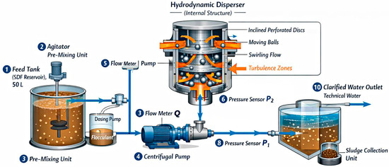
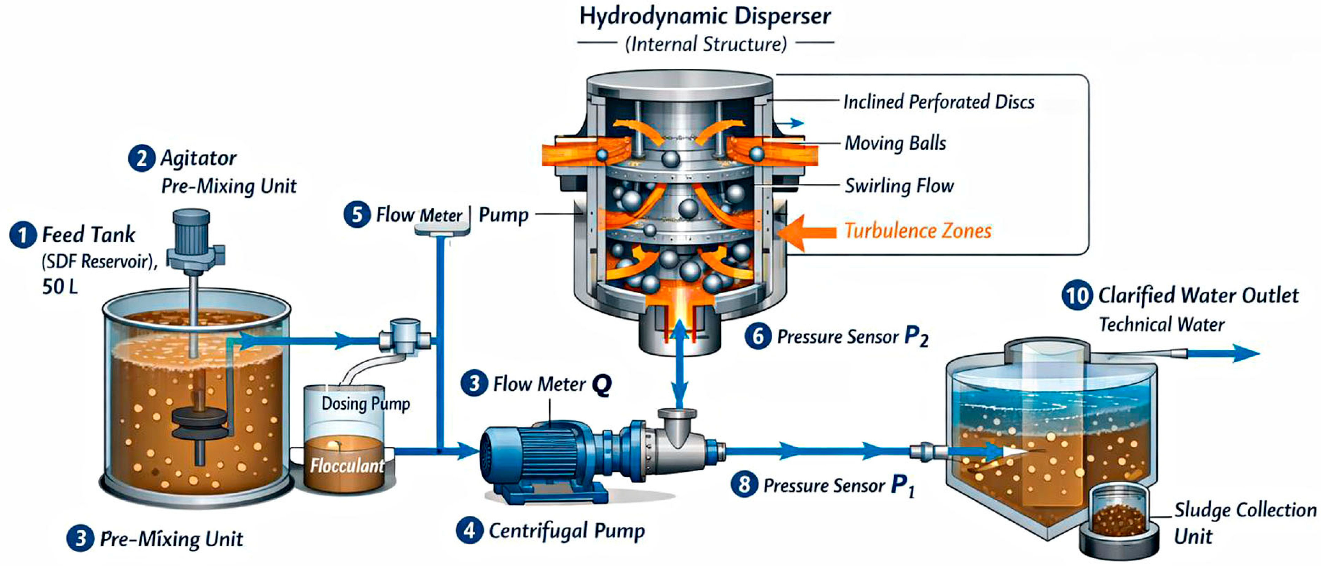
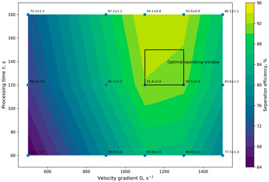
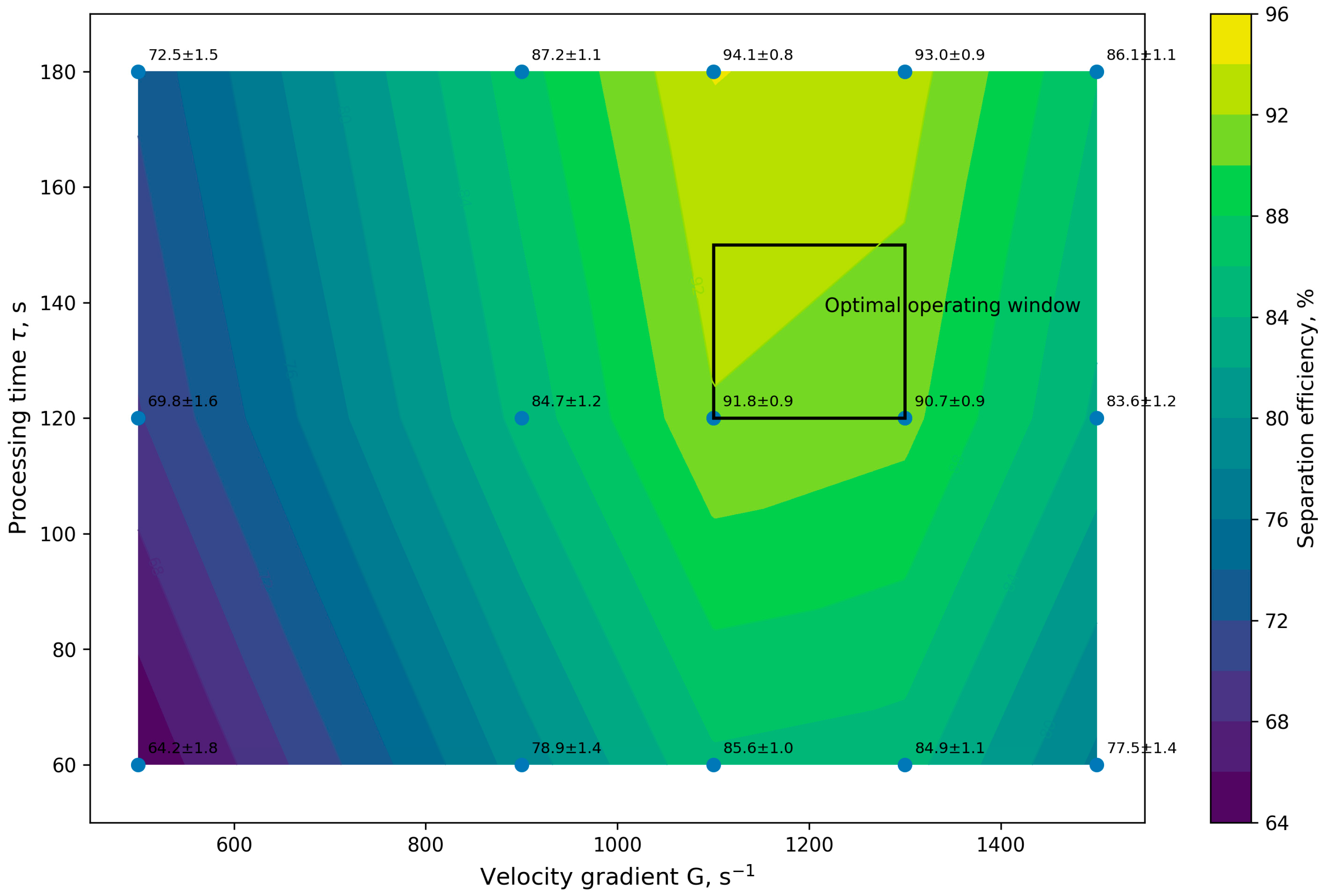
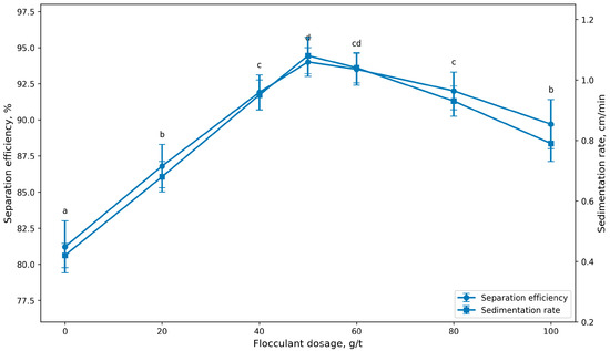
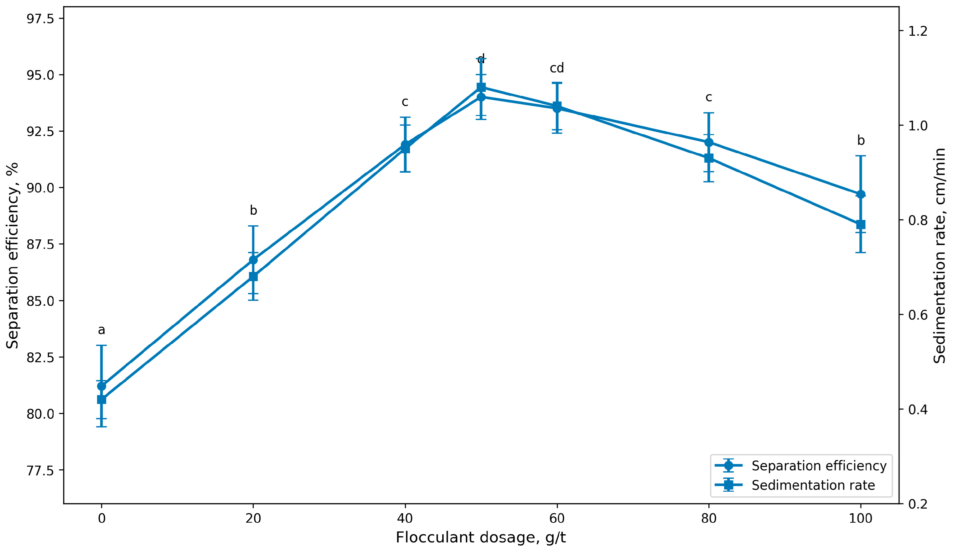
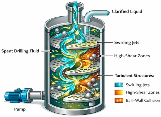
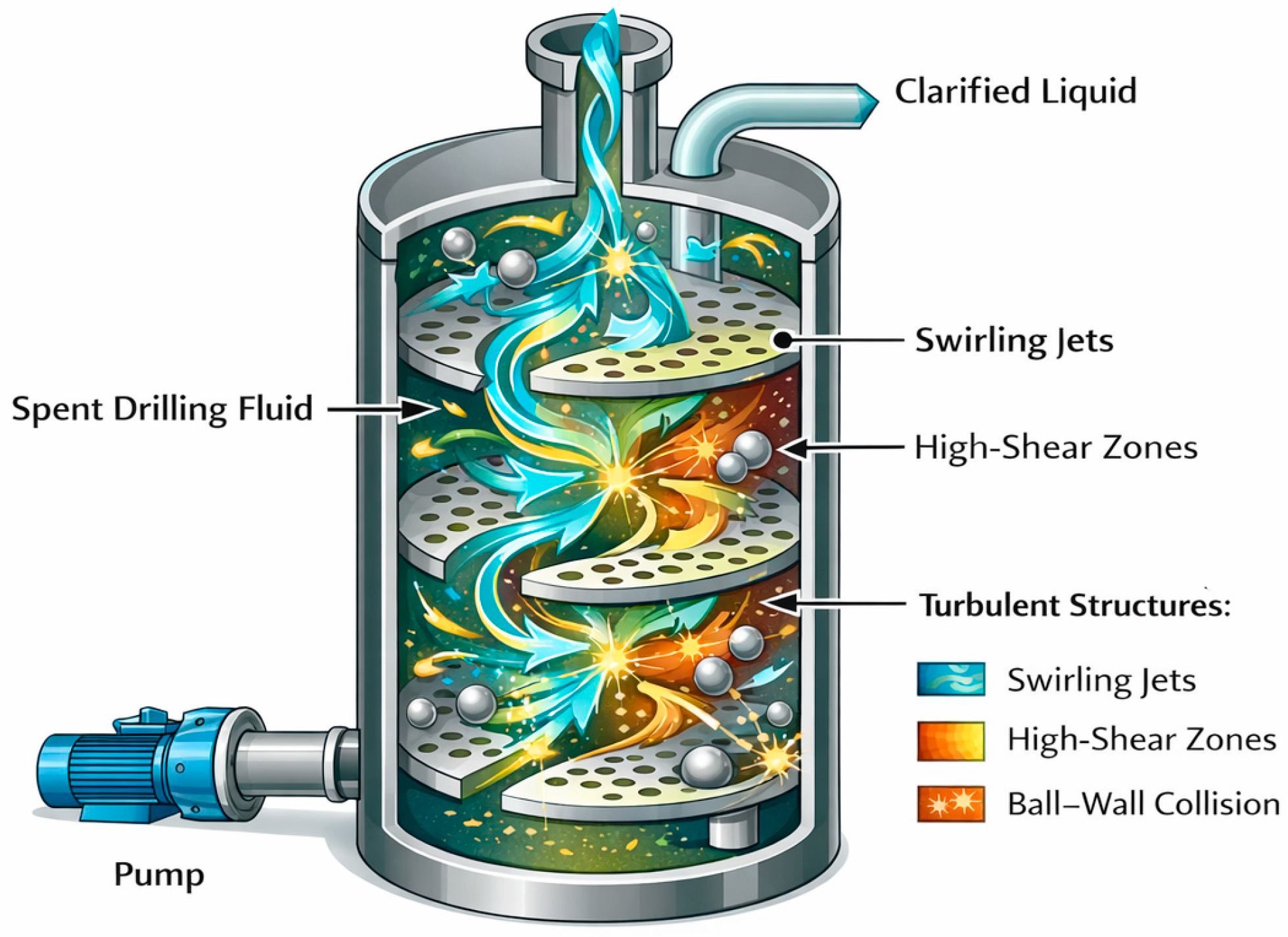
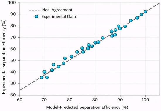
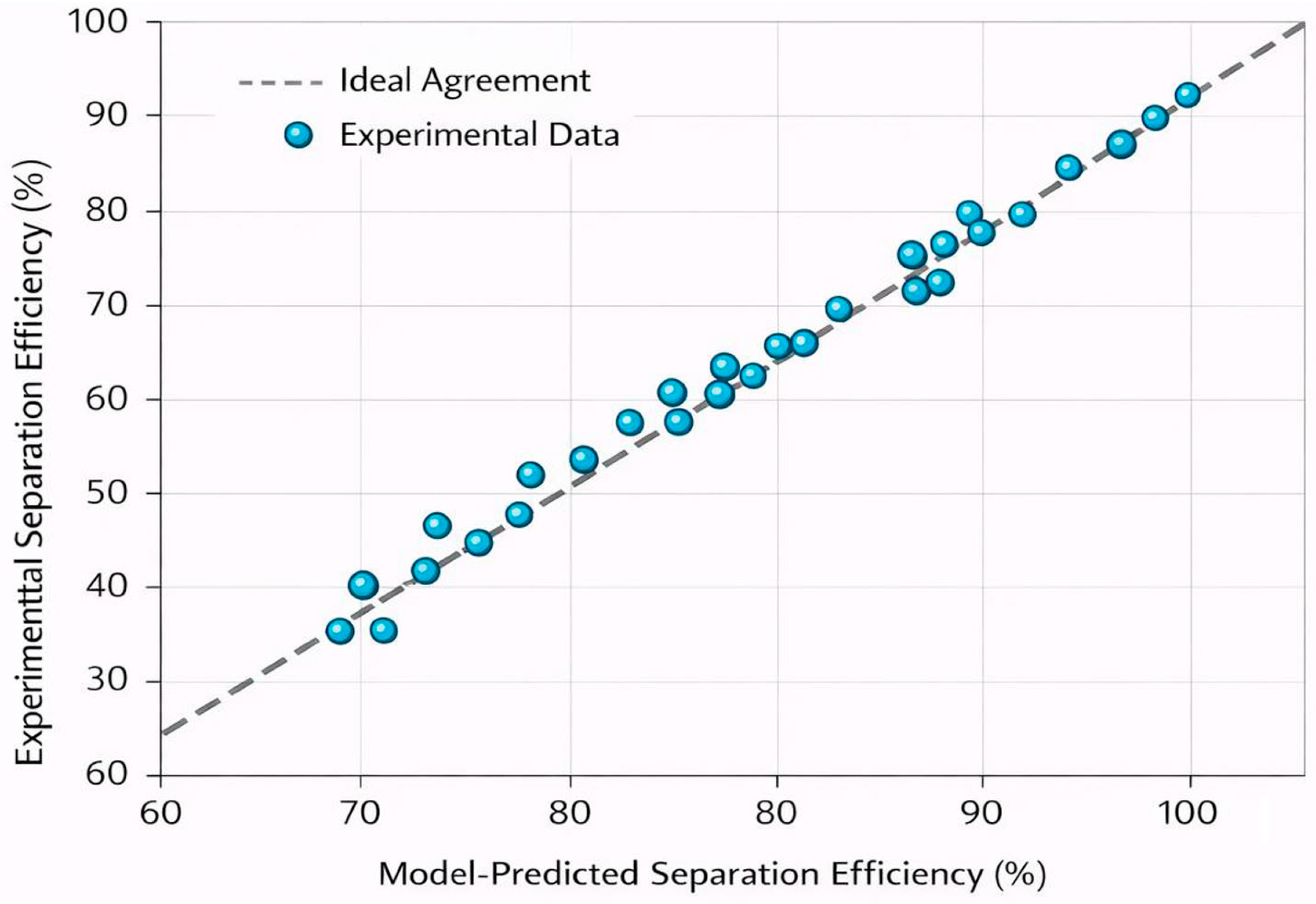
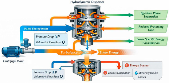
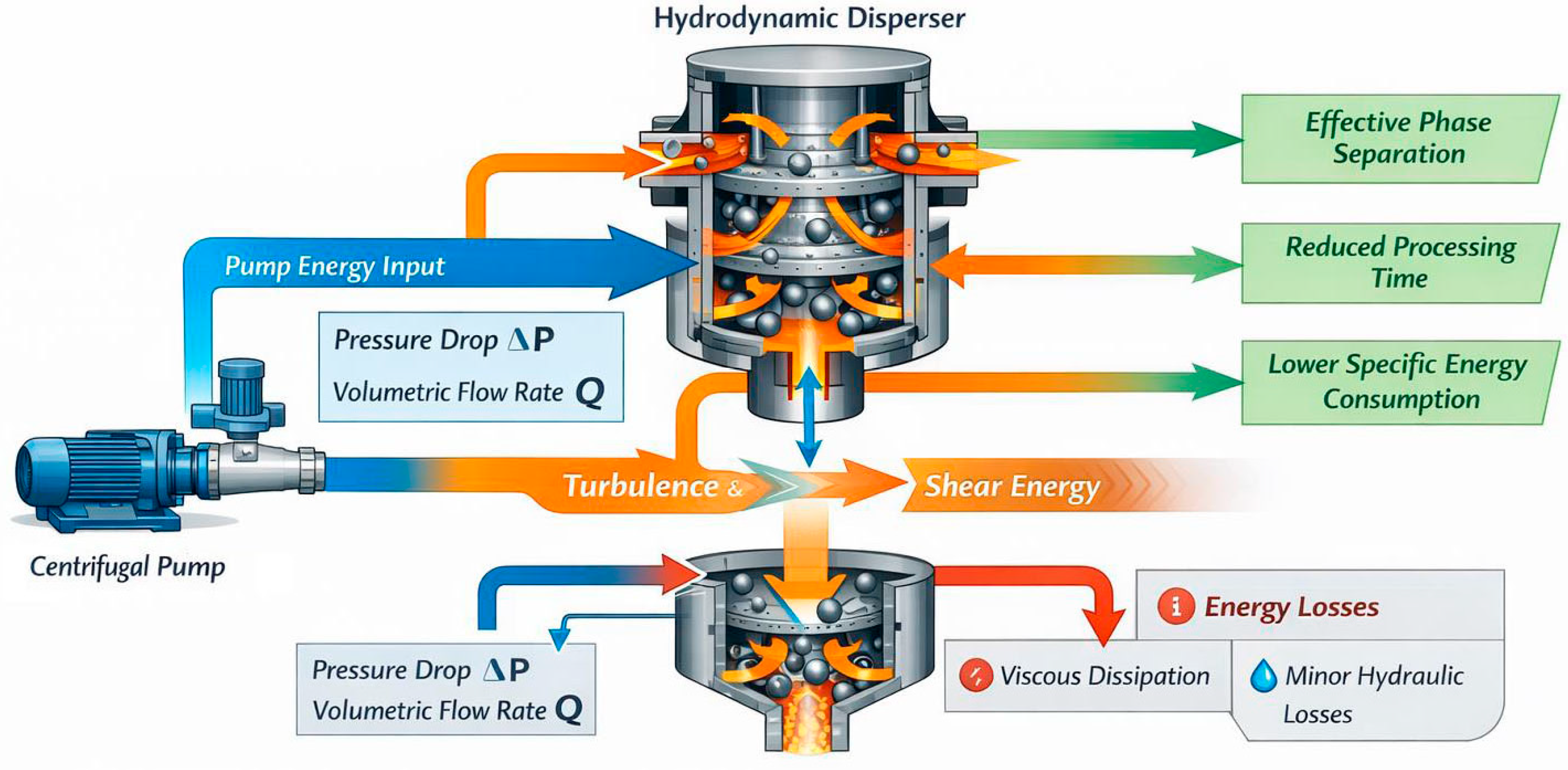
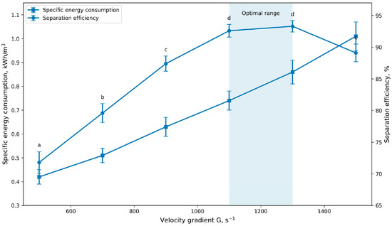
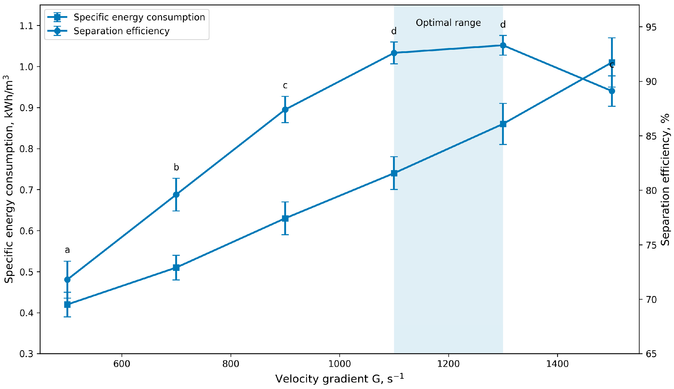
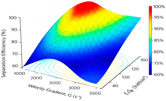
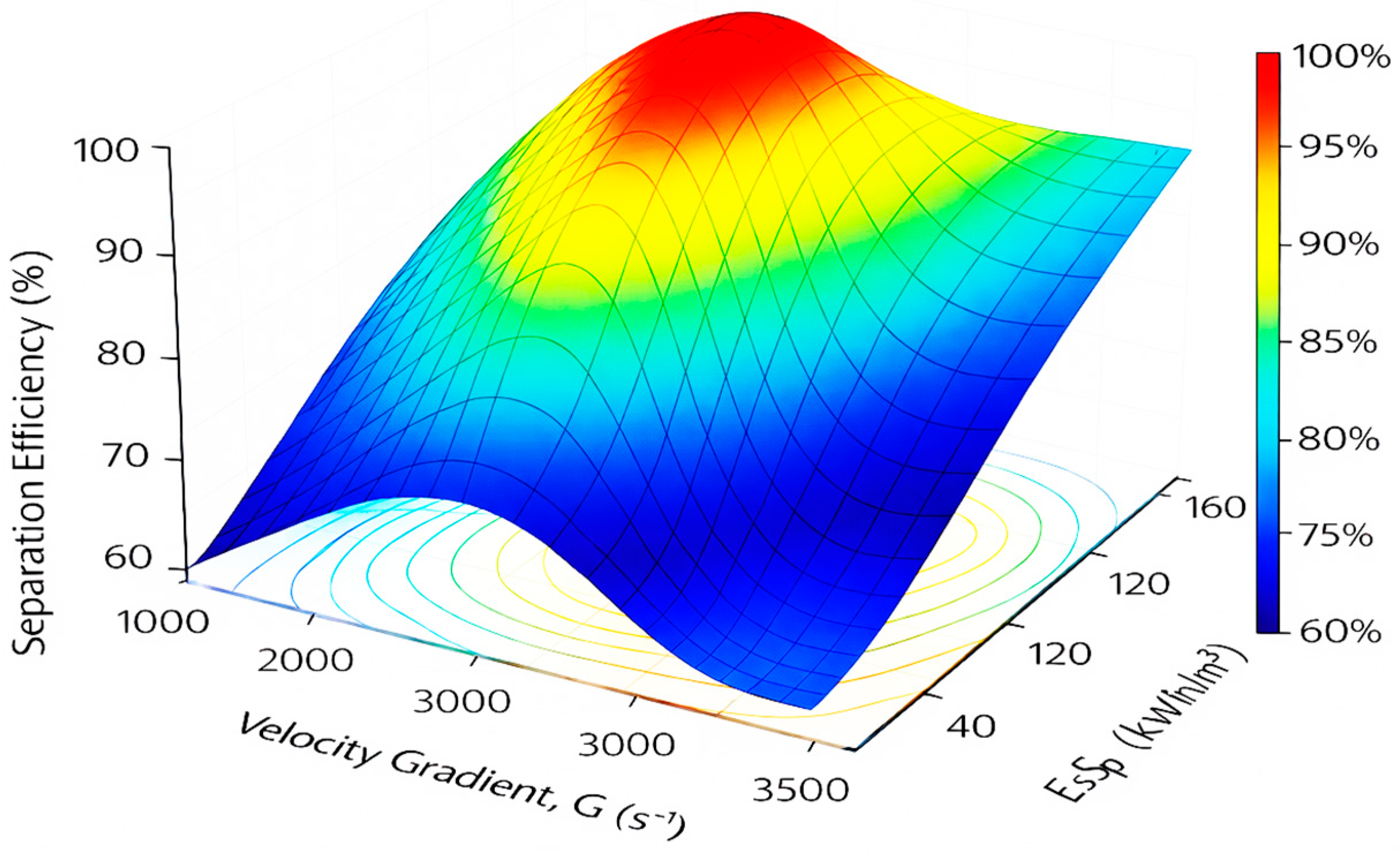
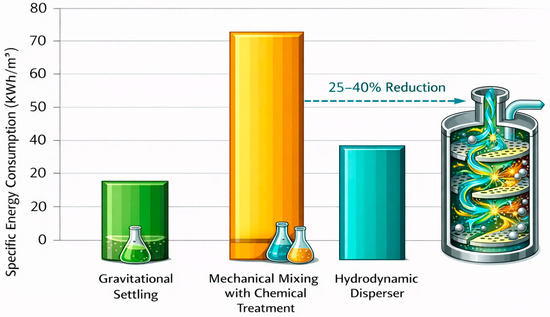
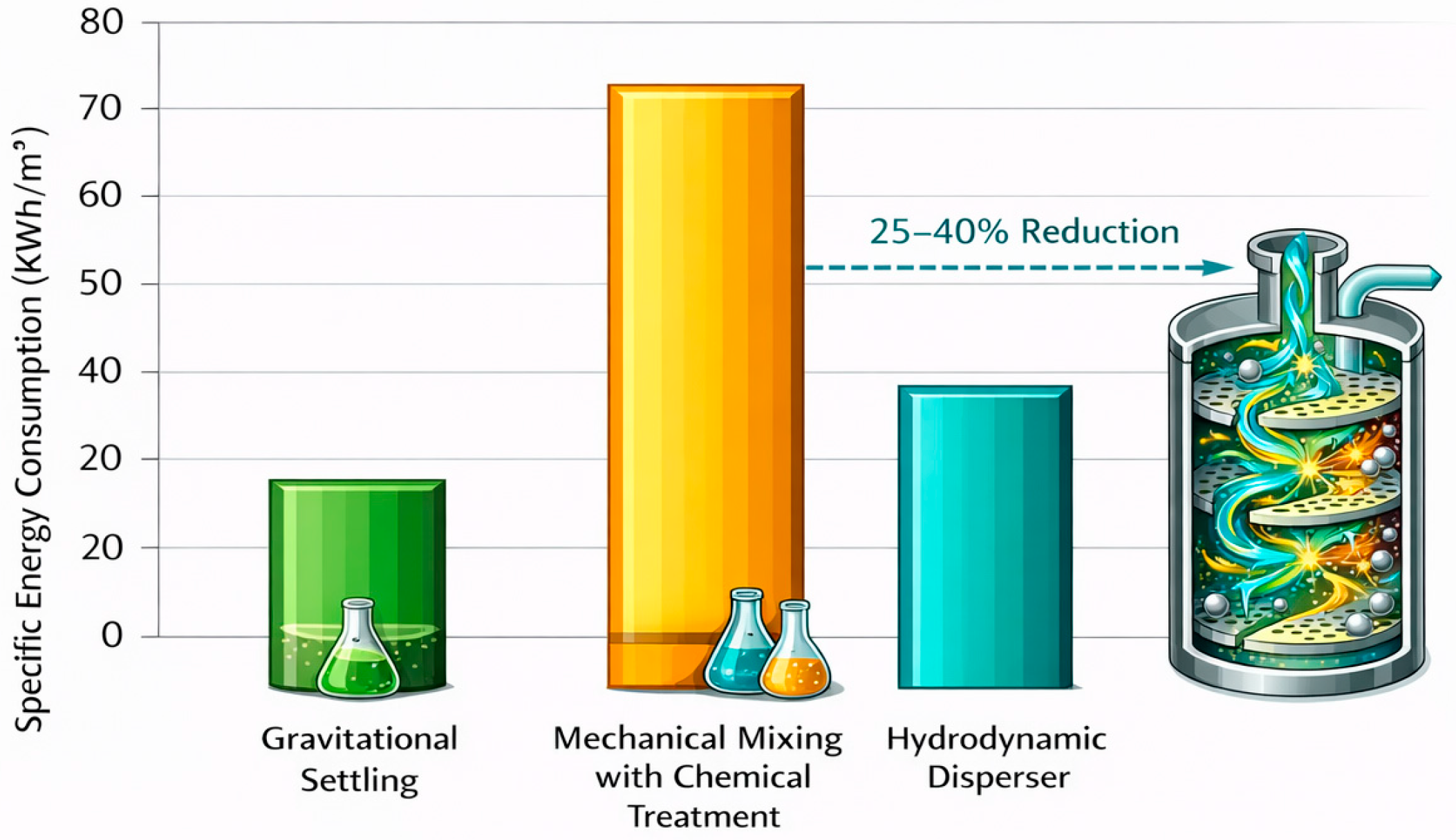
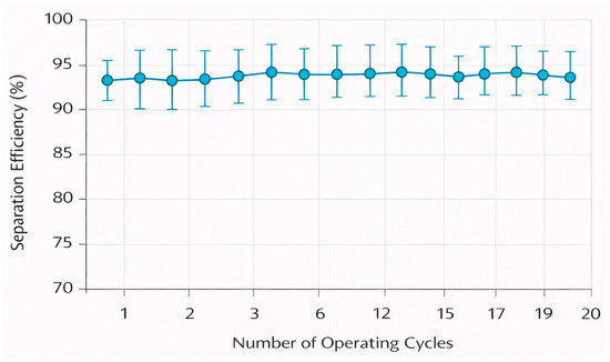
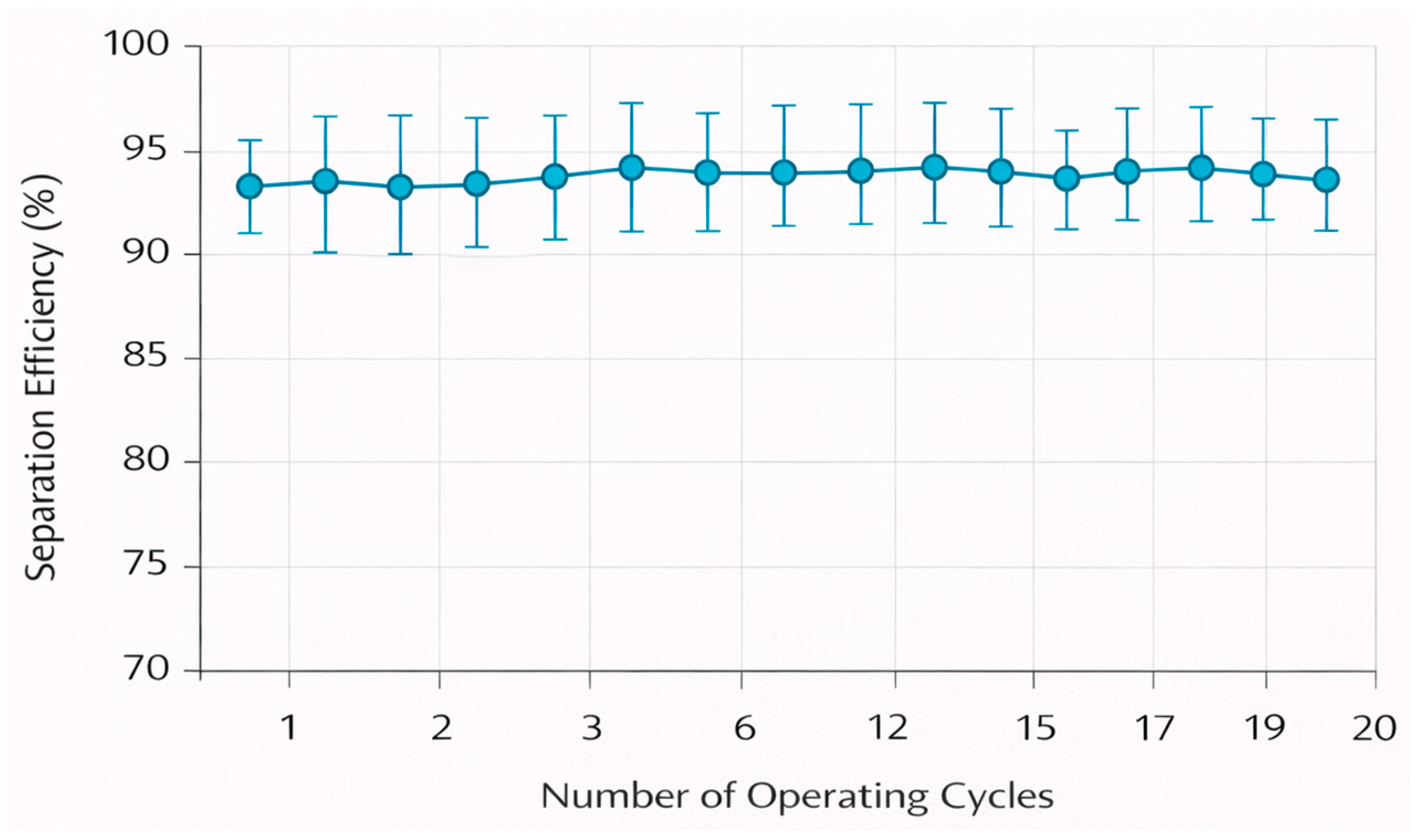
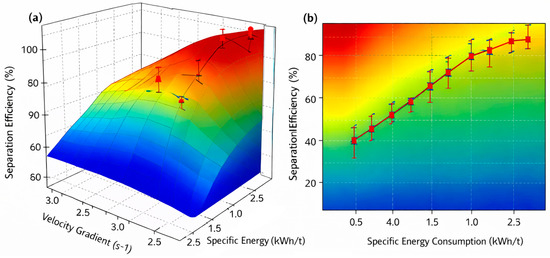
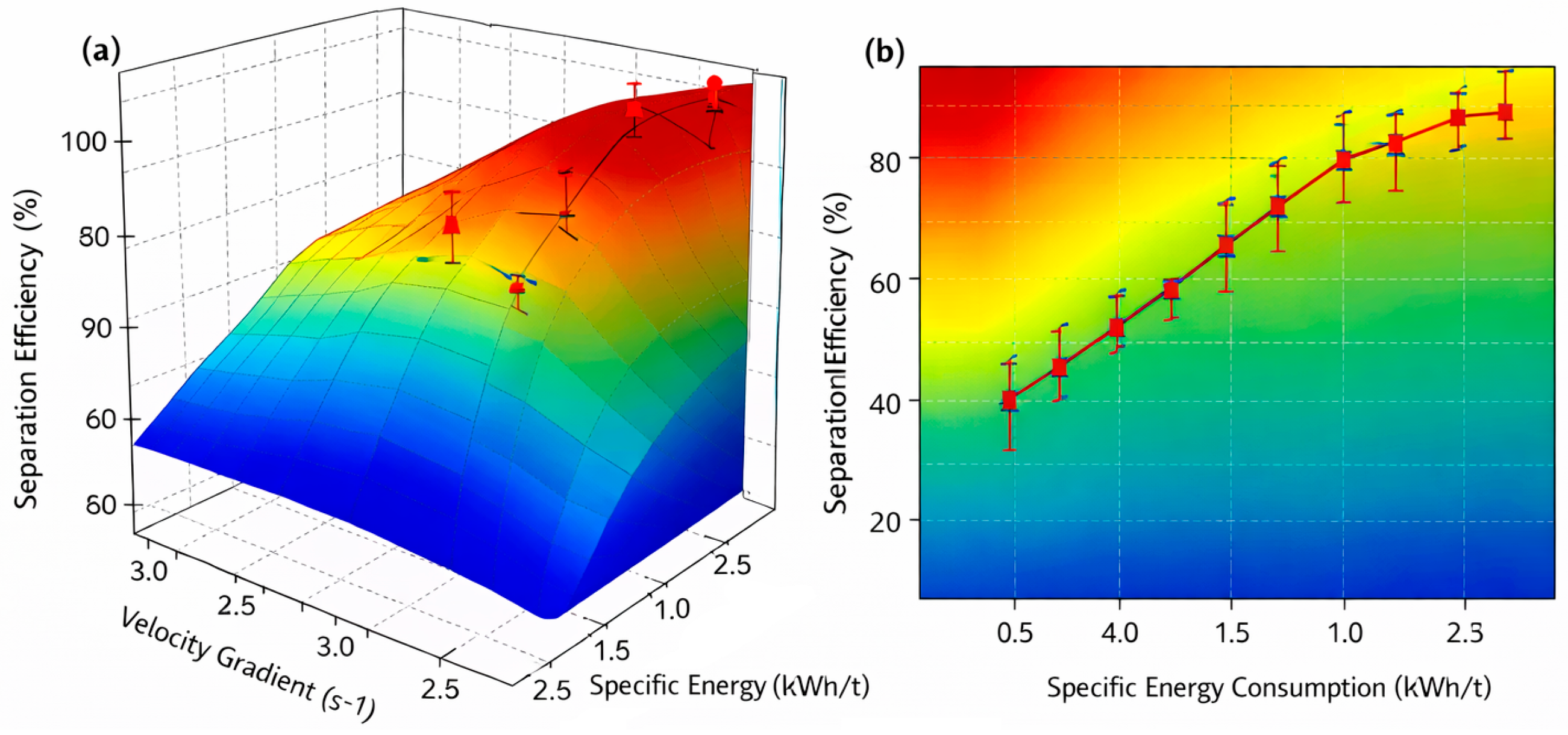
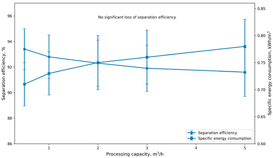
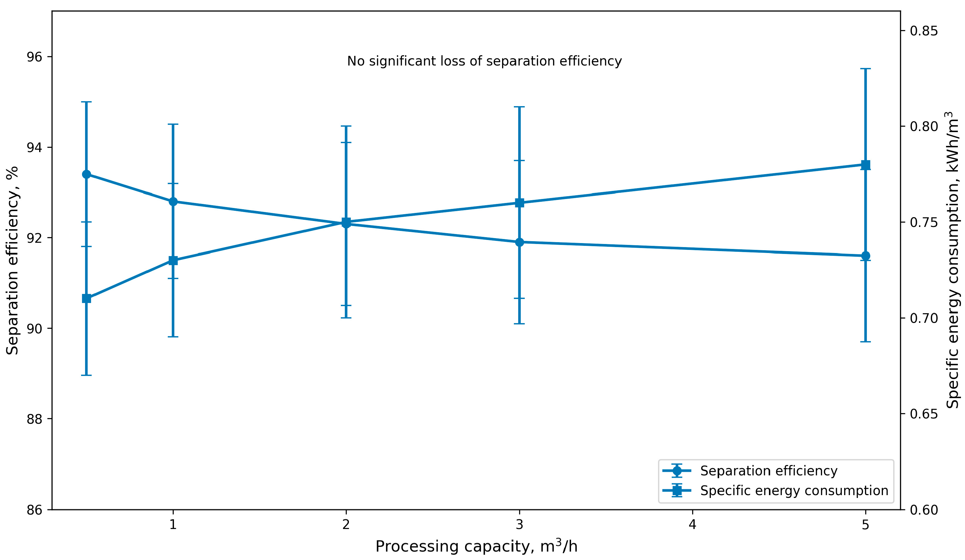
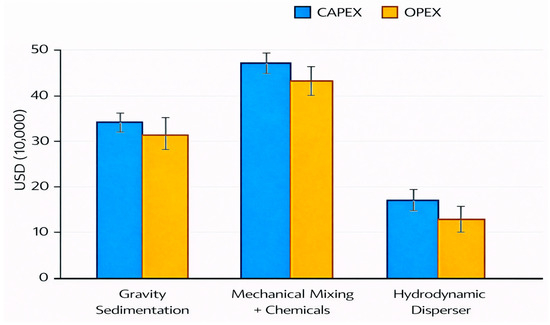
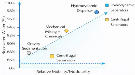
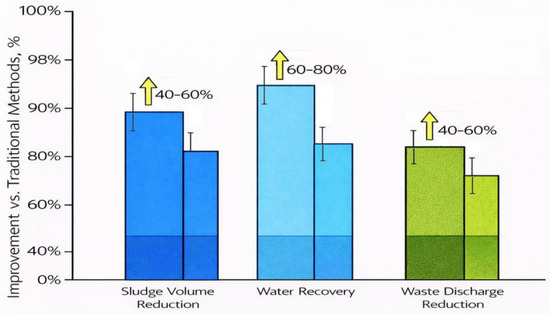
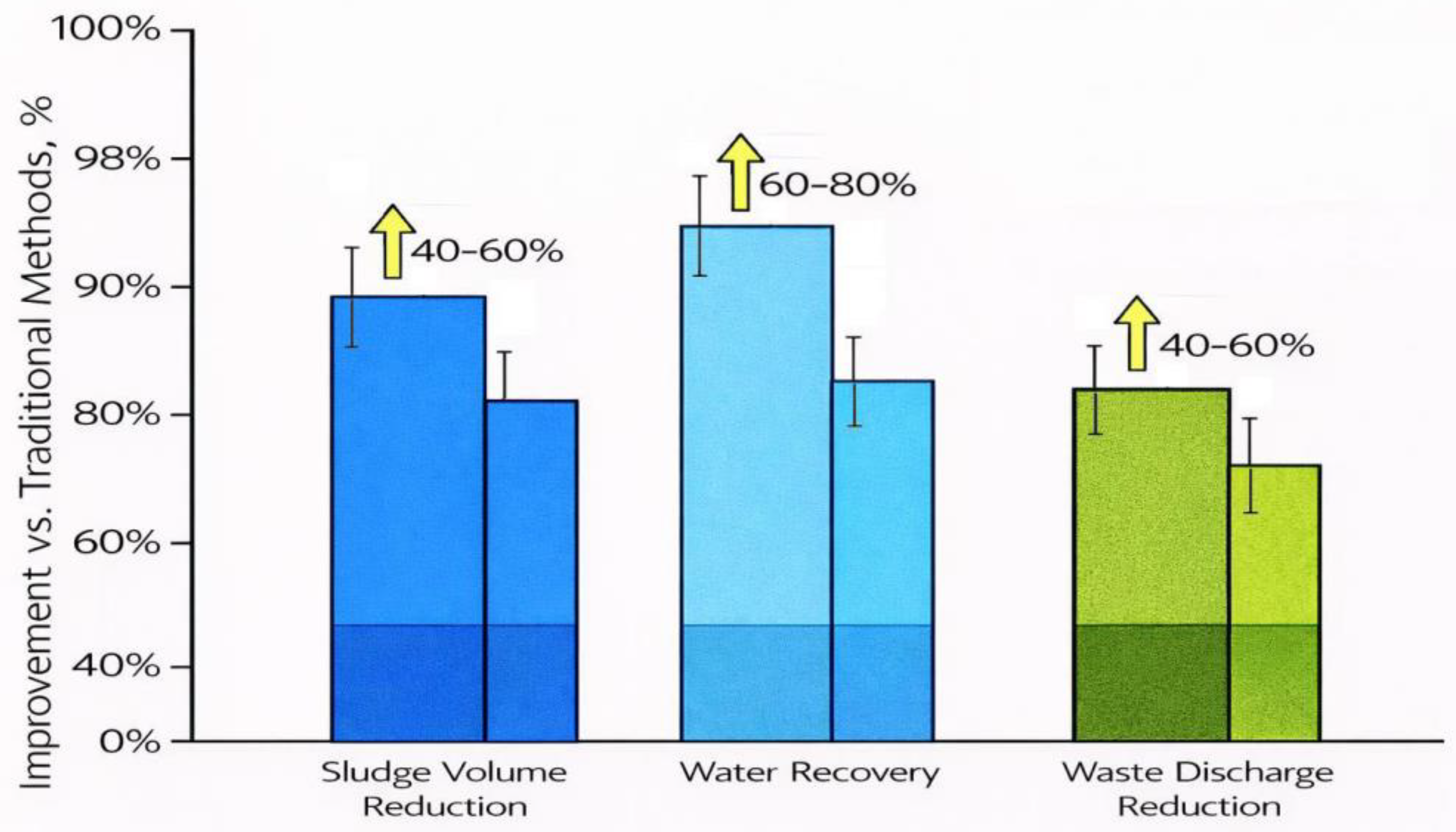

Disclaimer/Publisher’s Note: The statements, opinions and data contained in all publications are solely those of the individual author(s) and contributor(s) and not of MDPI and/or the editor(s). MDPI and/or the editor(s) disclaim responsibility for any injury to people or property resulting from any ideas, methods, instructions or products referred to in the content. |
© 2026 by the authors. Licensee MDPI, Basel, Switzerland. This article is an open access article distributed under the terms and conditions of the Creative Commons Attribution (CC BY) license.