


Abstract
Driven by the global energy transition, the rapid expansion of photovoltaic (PV) capacity—particularly in China’s “sand-Gobi-desert” mega-bases—demands highly efficient collection technologies. DC collection, offering low losses, compactness, and high reliability, is emerging as a critical solution for large-scale integration. This paper provides a comprehensive review of PV DC step-up collection systems. First, it analyzes typical network architectures, compares AC versus DC schemes, and examines design constraints imposed by DC bus voltage levels. Second, control strategies are summarized across device, equipment, and system levels. Third, based on engineering practices in ultra-large-scale bases, key challenges regarding fault detection, efficiency optimization, economic viability, and grid code compatibility are identified alongside representative solutions. Finally, future trends in high-voltage hardware maturation, protection bottlenecks, real-time artificial intelligence, and specialized standardization are proposed. This study serves as a vital reference for the topology design and engineering standardization of PV DC collection systems.
1. Introduction
Driven by the global energy transition and the advancement of the “Carbon Peaking and Carbon Neutrality” targets, photovoltaic (PV) generation has emerged as a primary contributor to newly installed capacity, benefiting from its abundant resources, technological maturity, and rapidly declining costs [1,2,3]. In the deserts, Gobi, and wastelands of Northwest China, commonly referred to as the “Sand-Gobi-Desert” regions, the deployment of ultra-large-scale PV projects is accelerating [4]. These projects are characterized by large bases, centralized development, and bulk transmission, with the installed capacity of individual bases evolving from hundreds of megawatts (MW) to the gigawatt (GW) level and beyond [5]. However, such engineering projects typically confront challenges including long transmission distances, harsh environmental conditions, and integration into weak grids. Consequently, these factors impose more stringent requirements on the efficiency, reliability, and controllability of PV collection and transmission systems. As installed capacities scale from megawatts to gigawatts and transmission distances extend, traditional AC collection systems increasingly face limitations regarding line losses, voltage drops, and excessive cabling costs [6,7,8]. In contrast, DC step-up collection systems—characterized by higher efficiency, compact footprint, and seamless integration with energy storage systems (ESSs)—are emerging as a critical solution for next-generation large-scale grid integration [9,10,11].
However, the transition to medium- and high-voltage (MV/HV) DC collection introduces significant engineering challenges. Firstly, high-power DC/DC converters and DC circuit breakers are not yet fully mature regarding insulation design and loss control. Secondly, due to the rapid rise rate of DC faults, existing AC-based protection experiences cannot be directly replicated [12,13,14]. Thirdly, the lack of dedicated grid codes for large-scale DC integration restricts interoperability.
In response to these challenges, scholars worldwide have conducted extensive research on PV grid integration, DC collection for wind and PV plants, flexible DC transmission, and DC distribution, resulting in a series of review works. For instance, some reviews focus on the grid-connected control of PV inverters and power quality conditioning technologies [15,16,17,18]. Others concentrate on DC collection and protection strategies for wind power and multi-terminal flexible DC systems [19,20]. Furthermore, certain literature discusses system architectures and control technologies from the broader perspective of architectures and control technologies or renewable DC microgrids [21,22]. Overall, existing reviews predominantly focus on AC collection scenarios or general DC systems. A comprehensive review is lacking for “MV and HV PV DC step-up collection systems” specifically tailored for ultra-large-scale PV bases in “Sand-Gobi-Desert” regions. Notably, significant gaps remain regarding the selection principles for bus voltage levels, multi-level control coordination across devices, equipment, and systems, as well as the deep coupling with flexible DC transmission, energy storage, and active grid-forming technologies.
To bridge these gaps, this paper provides a comprehensive engineering-oriented review. The main contributions are as follows:
- Architecture and Voltage Selection: A comparative evaluation of AC vs. DC topologies is presented, clarifying selection principles for DC bus voltage levels based on techno-economic constraints.
- Hierarchical Control Framework: A “device-equipment-system” control hierarchy is synthesized, covering wide-bandgap device driving, converter regulation, and station-level coordination.
- Bottleneck Identification: Key technical barriers, particularly in protection and efficiency optimization, are identified, and future perspectives are proposed for high-voltage hardware and intelligent self-healing technologies.
The structure of this paper is organized as follows: Section 2 introduces the typical network architectures, voltage levels, and relevant standards of PV DC step-up collection systems. Section 3 reviews control strategies and key technologies from the device, equipment, and system levels. Section 4 analyzes the primary technical challenges and development requirements encountered in large-scale engineering applications. Finally, Section 5 concludes the paper and provides an outlook on future research directions.
Review Methodology
This review adopts a structured and transparent literature survey methodology aimed at mapping the technological landscape of PV DC boosting and collection systems for large-scale power plants. This study follows the scoping review framework to synthesize representative and influential engineering studies that support comparative technical analysis and practical decision-making.
Relevant literature was retrieved from major scientific and engineering databases, including Web of Science, Elsevier Scopus, and IEEE Xplore, with Google Scholar used as a complementary source. Given the strong concentration of large-scale photovoltaic DC collection projects in China, the China National Knowledge Infrastructure (CNKI) database was additionally consulted to capture representative engineering studies and system-level analyses reported in Chinese. These sources were used to supplement practical design experience and engineering perspectives, while the core technical comparison relies on peer-reviewed international literature.
Search queries were constructed using combinations of keywords related to system architecture, voltage boosting, and DC collection, such as “photovoltaic DC collection,” “DC boosting topology,” “medium-voltage DC collection,” “large-scale photovoltaic power plants,” and “DC protection and control.” Boolean operators and keyword variations were applied to adapt to the search rules of different databases.
The initial search results were screened through a multi-stage selection process. In the first stage, titles and abstracts were reviewed to remove publications clearly unrelated to photovoltaic DC collection systems, such as low-power electronics or purely residential DC applications. In the second stage, full-text screening was performed to retain studies that provide explicit technical descriptions, performance analysis, or system-level insights relevant to large-scale photovoltaic installations.
The inclusion criteria focused on peer-reviewed journal articles and selected high-impact conference papers that present topology design, control strategies, voltage level selection, protection schemes, or operational experience of DC collection systems. Conference papers were retained when they reported first-of-a-kind architectures, prototype validation, or protection concepts that are not yet extensively covered in journal publications. Editorials, short communications, and non-technical reports were excluded.
To reflect recent technological progress while maintaining historical continuity, this review primarily considers literature published between 2015 and 2025, with increased emphasis on studies from 2020 onward, corresponding to the rapid development of medium- and high-voltage DC collection technologies and wide-bandgap power devices. In addition, a limited number of earlier technical standards and foundational documents published before 2015 are selectively cited where necessary. These references are included not for comparative performance evaluation but to provide baseline definitions, fundamental protection principles, and long-term system requirements that continue to underpin current photovoltaic DC collection system design.
Based on this process, 147 representative references were selected for detailed analysis. The overall literature selection workflow and scope definition are summarized in Figure 1, which illustrates the progressive narrowing from the initial search pool to the final reference set.
Figure 1.
Literature selection and review scope.
2. PV DC Step-Up Collection Systems: Architectures, Voltage Levels, and Standards
2.1. PV Collection System Architectures and Topologies
In large-scale PV power plants, the collection system undertakes the core functions of stepping up, collecting, and transmitting the output power from dispersed PV arrays. Its network architecture directly influences the efficiency, reliability, and scalability of the system [23]. While traditional solutions predominantly employ AC step-up collection architectures, the DC step-up collection architecture is gradually becoming a significant development direction as installed capacities and voltage levels continue to rise. Based on the electrical forms on the collection side and the energy flow paths, existing PV collection system architectures can be broadly categorized into AC collection, DC collection [24,25,26].
2.1.1. AC Collection System Architectures
AC collection developed early and features relatively mature technology. Consequently, early renewable energy projects frequently adopted this approach. Its basic structure is illustrated in Figure 2. As depicted, the power flow originates from the PV strings, undergoes DC/AC conversion through distributed inverters, and then passes through multiple transformation stages. Although this architecture is technically mature, several critical components, particularly low-voltage AC cables and multi-stage frequency transformers, introduce substantial inductive reactive power losses and magnetic core losses, thereby limiting overall system efficiency. This architecture is suitable for small- and medium-scale PV power plants, benefiting from mature technology and comprehensive standards. However, as station capacity and transmission distance increase, the system losses and equipment footprint of AC collection gradually escalate. Particularly in applications for ultra-large-scale PV bases, issues such as high current-related losses, bulky equipment, and excessive land occupation have become increasingly apparent [27,28,29].
Figure 2.
Structural diagram of the AC collection system.
2.1.2. DC Collection System Architectures
The DC collection system aggregates power from dispersed PV arrays via a medium-voltage MVDC bus. By eliminating reactive power circulation, this architecture significantly reduces line losses during long-distance transmission. Compared to conventional AC schemes, DC collection offers superior efficiency and higher power density [30,31,32,33]. These attributes make it particularly advantageous for applications in remote environments, such as desert regions. The fundamental topology of a DC collection system is depicted in Figure 3. Unlike the AC architecture, the power flow here remains in the DC domain until the final grid interface, eliminating reactive power circulation loops. In DC collection configurations, network topologies can be categorized into all-DC and partial-DC collection structures [34,35]. The former is further subdivided into all-DC parallel and all-DC cascaded PV system configurations, as depicted in Figure 3a and Figure 3b, respectively.
Figure 3.
Structural diagram of the DC collection system. (a) all-DC parallel collection topology. (b) all-DC cascaded collection topology.
For large-scale PV bases, particularly in desert regions, all-DC collection is essential for optimizing efficiency and minimizing transmission losses. By maintaining a continuous DC path from the PV arrays to the grid interface, this architecture eliminates redundant conversion stages, thereby enhancing overall system reliability and maintainability [36,37,38].
In an all-DC parallel collection system, multiple independent PV arrays are connected to dedicated DC/DC converters. These converters step up the array voltage to the MVDC level before aggregation onto a common bus. This topology is characterized by its modularity, flexibility, and robust fault isolation capabilities. Specifically, each sub-array performs independent Maximum Power Point Tracking (MPPT) [39,40,41]. From a protection perspective, as shown in Figure 3a, the parallel connection implies that a fault on the main DC bus can be fed by all connected converters. Therefore, the practical feasibility of this architecture relies heavily on the coordination between fast-acting DC circuit breakers and the fault-blocking capability of the DC/DC converters to achieve rapid current interruption and selective fault isolation. Consequently, this architecture offers high reliability.
All-DC cascaded systems achieve high-voltage DC output by connecting multiple PV arrays and their associated DC/DC converters in series [42,43]. This architecture is ideal for applications requiring high voltage levels, as the series stacking of modules effectively reduces current stress and enhances power density. Compared to parallel topologies, cascaded configurations offer superior scalability and higher voltage capabilities. However, this series connection imposes stringent requirements on voltage balancing and component consistency. A critical architectural challenge highlighted in Figure 3b is current interruption. Since all modules share the same current path, a failure in a single unit does not naturally isolate itself but threatens the entire string’s continuity. Therefore, engineering implementations must integrate reliable bypass protection schemes to short-circuit failed modules instantly, ensuring continuous operation of the remaining healthy units. Consequently, system design must prioritize robust voltage equalization control and active bypass mechanisms.
2.1.3. Engineering Comparison of PV Collection Architectures
While the above subsections introduce the structural characteristics of AC and all-DC PV collection architectures, practical deployment in large-scale PV plants requires a systematic evaluation of their engineering trade-offs. In particular, conversion efficiency, investment cost, system reliability, and ease of field maintenance play a decisive role in architecture selection.
It should be emphasized that performance indicators such as efficiency and reliability are not solely determined by the collection topology itself, but are also influenced by voltage level selection, power device technology, control strategies, and redundancy design. Nevertheless, at the architecture selection stage, different collection topologies impose distinct structural constraints—such as the number of conversion stages, current levels, modularity, and fault isolation capability—which lead to typical engineering tendencies observable across a wide range of practical implementations. Therefore, a qualitative, architecture-level comparison remains meaningful for early-stage engineering decision-making.
Based on these considerations, Table 1 provides a qualitative comparison of three representative PV collection architectures discussed above, namely the conventional AC collection system, the all-DC parallel PV collection system, and the all-DC cascaded PV collection system.
Table 1.
Comparison of three representative PV collection system.
As summarized in Table 1, conventional AC collection systems benefit from mature technology and straightforward maintenance procedures but suffer from additional power conversion stages and associated efficiency penalties. All-DC parallel PV collection architectures reduce conversion steps and improve overall efficiency while maintaining modularity and fault isolation, offering a balanced compromise between performance and maintainability. In contrast, all-DC cascaded PV collection systems enable higher voltage aggregation and lower current transmission, which can facilitate higher efficiency under comparable voltage and power ratings; however, these advantages are often accompanied by increased control complexity, more demanding protection requirements, and greater challenges in field maintenance.
This architecture-level comparison precedes voltage level selection and serves as a preliminary decision layer.
2.2. Voltage Level Selection for PV DC Collection Systems
Voltage level selection is a pivotal factor governing the design and economic viability of DC collection systems. Operating voltage directly impacts current ratings, line losses, equipment sizing, and insulation coordination [44,45,46]. As the scale of PV bases expands—particularly in desert regions—there is a growing demand for higher voltage DC solutions to accommodate bulk power transmission.
2.2.1. Voltage Levels in Existing DC Collection Projects
DC bus voltages in existing demonstration projects typically span from ±10 kV to ±50 kV, as detailed in Table 2. These real-world implementations confirm that MVDC is the superior choice for scaling up capacity and extending transmission distances. Consequently, MVDC has emerged as the dominant architecture for next-generation PV collection systems.
Table 2.
DC Collection Demonstration Projects in China.
Currently, the majority of PV DC collection demonstration projects are deployed in China [47,48,49,50]. In contrast, DC system research in Europe and North America predominantly focuses on offshore wind integration, distribution networks, and microgrid applications [51,52,53,54].
A 50 MW PV DC collection demonstration has been implemented at the Golmud PV Base in Qinghai [47], operating at a bus voltage of ±15 kV. The system comprises five 10 MW generation units connected to the DC bus. Each 10 MW unit is formed by cascading three separate DC/DC converter sub-units. This project is part of the 250 MW PV component within the “Challenge-Based Recruitment” Liquid Air Energy Storage (LAES) demonstration.
The 5 MW Xiaoyangshan PV All-DC Transmission Project in Zhoushan employs a multi-stage stepping scheme. The PV output (after MPPT) is boosted from 1.5 kV to a ±20 kV MVDC collection bus. Subsequently, a high-voltage DC transformer steps this up to the ±200 kV DC bus at the Zhoushan-Yangshan Station. The harvested power is then directly transmitted through the Zhoushan flexible DC grid [48].
The Gantangzi PV Power Station in Yunnan (Dali) commissioned the first large-scale ±30 kV/5 MW PV DC step-up grid-connected system [49]. This project pioneered a high-efficiency all-DC step-up topology and its associated control methodologies. Key hardware developments included a ±30 kV/1 MW centralized DC step-up converter and a 20 kV/500 kW series DC converter. These innovations successfully addressed critical technical challenges regarding high-power, high-step-up-ratio DC conversion.
A 1.5 MW PV DC step-up demonstration platform operating at ±35 kV has been established at the Zhangbei Test Base (National Energy Large-Scale Wind Power Grid-Connection System) [50]. The system topology features three parallel 500 kW DC/DC converters connected to a common ±35 kV DC bus. The aggregated power is subsequently inverted by a 2 MW Voltage Source Converter (VSC) and injected into the local 35-kV AC distribution grid.
2.2.2. Influencing Factors for Voltage Level Selection
The selection of voltage levels for PV DC collection systems fundamentally constitutes a multi-objective optimization problem that balances technical feasibility, economic viability, and safety considerations. The optimal voltage level often varies across different engineering scenarios, necessitating a comprehensive assessment of multiple factors, including installed capacity, transmission distance, topographical configuration, power device and equipment standards, insulation and environmental conditions, grid connection specifications, and operational maintenance (O&M) requirements [51,52,53].
- Installed capacity and transmission distance
For a fixed power transmission, increasing the DC bus voltage reduces line current, leading to a quadratic reduction in resistive losses (I2R) and enabling the use of smaller conductor cross-sections. This is particularly critical for large-scale PV bases with transmission distances exceeding tens of kilometers, where lower voltage levels (e.g., <±10 kV) become economically unviable due to excessive losses and cabling costs [54,55]. Consequently, stepping up to ±15 kV, ±30 kV, or higher is often necessary. However, higher voltages impose stricter requirements on insulation and substation equipment, driving up capital expenditure (CAPEX) [56,57]. Therefore, the optimal voltage selection represents a trade-off between operational expenditure savings from reduced losses and the increased CAPEX of high-voltage equipment.
- 2.
- System topology and access methods
The sensitivity of a system to voltage levels varies significantly across bus topologies. In radial parallel structures, elevating the bus voltage requires upgrading the voltage ratings of all connected DC/DC converters and breakers, making device-level insulation and switching capabilities the primary bottlenecks [58,59,60]. Conversely, in cascaded or multilevel configurations, the total DC voltage is distributed across series-connected modules, alleviating individual voltage stress. But this benefit comes at the cost of increased complexity in voltage balancing control and module consistency. Furthermore, if the collection bus connects directly to an upstream flexible DC transmission system or a DC distribution grid, voltage compatibility becomes paramount. Mismatched levels necessitate additional DC transformers, which in turn impose upstream constraints on the optimal selection of the collection voltage.
- 3.
- Power device and electrical equipment technology level
The feasibility of bus voltage levels is strictly bounded by the capabilities of available power devices. The ratings and reliability of high-voltage IGBTs/IGCTs, SiC modules, DC circuit breakers, and MVDC converters are the decisive factors [61,62]. In the absence of standardized high-voltage products, selecting an overly aggressive voltage level can lead to sourcing difficulties, inflated costs, and extended lead times. Although advancements in SiC technology and high-voltage DC switching are gradually broadening the feasible voltage envelope, current engineering practices must still strike a balance between leveraging mature, off-the-shelf components and adopting future-proof designs.
- 4.
- Insulation coordination, electrical clearances and environmental conditions
Higher voltage levels directly translate to stricter insulation and clearance requirements. Designing MVDC/HVDC systems involves evaluating critical parameters like power frequency withstand voltage, impulse withstand voltage, transient overvoltage, and polarity reversal to establish robust internal and external insulation schemes [63,64,65,66]. Environmental constraints are pivotal. In “Sand-Gobi-Desert” regions, characterized by heavy pollution, high altitude, extreme temperature swings, and sandstorms—designers must prioritize creepage distance, pollution levels, and altitude correction factors. High voltage exacerbates the demand for larger external insulation dimensions and a greater station footprint [67]. Consequently, indiscriminate voltage escalation is ill-advised in harsh environments. Final voltage selection requires rigorous verification against local pollution data, meteorological conditions, and operational maintenance capabilities.
- 5.
- Grid connection specifications, power quality and system stability requirements
Grid integration imposes constraints on DC voltage selection. Since collection systems interface with the grid through inverters or flexible DC stations, the chosen voltage must align with grid codes, power quality standards, and stability requirements [68,69,70]. Higher DC voltage offers dual impacts. On the positive side, it boosts power density and control margins, enhancing reactive power support and fault ride-through capabilities. Conversely, it leads to faster fault current rise rates (di/dt) and higher energy concentration during faults, stressing protection systems and current-limiting technologies. Optimal voltage selection thus requires balancing these factors, coordinating closely with control strategies, fault response mechanisms, and power quality measures.
- 6.
- Investment Costs, lifecycle economics, and reliability
Voltage uprating presents a classic economic trade-off. Higher voltages reduce resistive losses and cabling requirements, driving down long-term operational expenditures. Conversely, they inflate CAPEX for high-voltage equipment, insulation, and civil works. Lifecycle cost analysis typically reveals a U-shaped curve or an L-shaped stabilization trend as voltage increases [71,72,73]. Reliability introduces uncertainty. High-voltage adoption often involves novel equipment and complex control schemes, the long-term reliability and operational maintenance demands of which require field validation. Decision-making must therefore look beyond initial investment. A holistic evaluation prioritizing total lifecycle costs (LCC) and system reliability is essential for determining the optimal voltage level.
- 7.
- Scalability and operational conditions
Large-scale PV bases are usually developed in stages and commissioned in phases. Consequently, voltage level selection must accommodate future expansion capabilities. While lower voltage levels may minimize initial capital outlay, they often create capacity bottlenecks during subsequent phases. Excessively high voltages can result in low utilization rates and inflated upfront costs [74,75,76]. Furthermore, practical constraints such as operational maintenance technical proficiency, spare parts inventory, and fault handling experience directly influence the feasibility of high-voltage solutions. These factors constitute critical design inputs that must be integrated into the preliminary planning phase.
In summary, selecting the voltage level for PV DC collection involves a complex, multidimensional trade-off among project scale, topological constraints, hardware limitations, environmental conditions, grid code compliance, and lifecycle economics. In engineering practice, this decision process typically employs techno-economic evaluation models or multi-objective optimization algorithms. These methods enable the identification of an optimal solution from candidate schemes, effectively balancing immediate operational needs with long-term developmental requirements.
2.3. Standards and Codes for PV DC Collection Systems
PV DC step-up collection systems encompass diverse domains, including PV module array cabling, DC distribution, power electronic conversion, and grid integration performance. Their engineering design and operational management depend heavily on a robust standardization framework. However, dedicated standards specifically for “PV DC collection” remain absent worldwide. Current engineering practices predominantly rely on adapting general standards from PV generation systems, DC distribution, flexible DC transmission, and existing grid codes.
2.3.1. Relevant Standards and Codes
At the international level, the International Electrotechnical Commission (IEC) provides the foundational framework for PV DC systems. IEC 62548:2016 serves as the global benchmark for PV array design, addressing DC-side safety, wiring, and protection, primarily for low-voltage applications [77]. This is complemented by IEC 62738:2018 for ground-mounted station design and IEC 60364-7-712:2017 for installation specifications [78,79]. Furthermore, IEC TS 61201:2007 defines critical DC voltage limits, facilitating insulation coordination essential for system safety [80].
Parallel to IEC, the Institute of Electrical and Electronics Engineers (IEEE) focuses on grid integration and auxiliary systems. The IEEE 1547 series is pivotal for distributed generation interconnection, with recent revisions progressively incorporating characteristics relevant to DC interfaces [81]. Additionally, IEEE 946-2020 provides specific design guidance for DC auxiliary power supplies, supporting the reliability of substation equipment [82].
In the context of equipment safety certification, particularly within the North American market, UL standards play a rigorous role. UL 1741 SA/SB establishes mandatory safety requirements for converters and interconnected system equipment [83]. Crucially, UL 1699B standardizes DC arc-fault circuit protection, addressing one of the most significant safety hazards in DC collection architectures [84].
Concurrently, driven by the rapid deployment of mega-scale renewable bases, China has developed a comprehensive set of national standards. GB/T 34933-2017 and GB/T 34936 specifically regulate PV combiner boxes, covering electrical, insulation, and protective aspects [85,86]. Broader station design is governed by GB/T 50797-2012 and GB/T 29196-2012, while the recently updated GB/T 32900-2025 defines advanced technical requirements for relay protection, reflecting the specific needs of large-scale integration [87,88,89]. The relevant standards involved are shown in Table 3.
Table 3.
Relevant standards.
2.3.2. Applicability Analysis
In current engineering practice, dedicated system-level standards for PV DC step-up collection systems are conspicuously absent. Consequently, project implementation typically relies on an “analogy and adaptation” strategy, leveraging existing standards from PV modules, grid interconnection equipment, DC distribution, and flexible DC transmission, alongside general electrical safety codes. While this framework of “relevant standards” provides a baseline for equipment selection, safety verification, and performance assessment, its applicability and depth are significantly limited when addressing the specific challenges of MVDC/HVDC station scenarios.
From the perspective of PV DC collection, the applicability and limitations of the existing standardization framework are primarily manifested in four key aspects:
- Guidance Gap in Voltage Levels and Insulation Coordination.
Current standards for DC distribution and flexible DC systems typically target low-voltage applications or specific high-voltage transmission tiers, leaving a regulatory vacuum for the ±10~±35 kV MVDC range typical of PV stations. Consequently, projects often resort to compromise designs referencing AC substation or HVDC norms [90]. This leads to inconsistent external insulation margins and station layouts across different engineering implementations.
- 2.
- Incompatibility of Fault Characterization and Protection Testing.
PV DC collection systems rely heavily on DC/DC converters and MV/HV DC circuit breakers, exhibiting fault signatures—specifically current rise rates and energy distribution—that differ fundamentally from AC systems [91,92]. Existing short-circuit testing protocols and protection setting methodologies are largely predicated on AC assumptions [93,94]. The lack of dedicated fault testing standards and performance metrics for DC topologies forces protection coordination and current-limiting strategies to rely disproportionately on simulation analysis and empirical experience rather than standardized verification.
- 3.
- Inadequate Adaptation to Extreme Environments.
Existing standards generally assume conventional environmental conditions for pollution classification, altitude correction, and enclosure ratings. They fail to adequately address the harsh realities of “Sand-Gobi-Desert” regions, such as heavy pollution, intense solar radiation, extreme diurnal temperature swings, and abrasive sandstorms. For MVDC/HVDC collection stations, these factors impose stringent constraints on external insulation, thermal management, and mechanical integrity, necessitating the development of targeted design and testing provisions.
- 4.
- Absence of System-Level Interoperability and Coordination.
PV DC collection systems operate as part of a complex ecosystem involving flexible DC transmission, energy storage, and automation platforms [95]. This integration spans multiple voltage levels, multi-vendor equipment, and diverse protocols. However, current standards remain device-centric or limited to single subsystems. There is a critical lack of unified specifications for interfaces, data models, and coordinated control boundaries within the integrated “PV-Storage-Transmission” architecture, hindering seamless interoperability.
3. Control Strategy for Photovoltaic DC Bus Systems
The escalating scale and voltage of photovoltaic DC collection systems mandate control paradigms that extend beyond individual converter stability to ensure optimal power distribution, bus regulation, and AC grid interaction across multi-terminal networks [96,97]. Distinct from conventional AC collection or low-voltage DC microgrids, large-scale deployments in arid regions involve elevated voltages, extensive topologies, heterogeneous equipment, and severe fluctuations. Addressing these complexities requires a tightly coupled, hierarchical control framework integrating device, equipment, and system levels.
Figure 4 depicts the proposed hierarchical control framework. As visually synthesized in this figure, the control architecture is decoupled into three distinct but interacting layers. This visualization maps the critical “cross-cutting” relationships: the device layer provides the physical actuation bandwidth, the equipment layer executes local regulation algorithms, and the system layer orchestrates global optimization constraints. Device-level control ensures reliable semiconductor switching under high voltage, current, and frequency conditions, underpinning high-performance converter design. Equipment-level control regulates individual or aggregated converters to execute MPPT, DC bus support, and grid-side power quality maintenance. System-level control leverages communication networks to coordinate power distribution across collection units and interfaces, facilitating rapid reconfiguration during disturbances.
Figure 4.
Hierarchical control framework.
3.1. Device Level Control
In PV DC collection systems, power semiconductor devices operate continuously under high-voltage, high-power-density, and variable thermal conditions. Their switching frequency and loss characteristics are the critical determinants of converter efficiency, volumetric density, and the complexity of thermal and insulation design [98,99,100]. The device landscape encompasses traditional thyristors and Insulated-Gate Bipolar Transistors (IGBTs), alongside emerging Wide-Bandgap (WBG) semiconductors—specifically SiC MOSFETs and GaN HEMTs, which have gained significant traction in recent years for their superior performance [101,102].
3.1.1. Device Type and Application Scenario
Power semiconductor devices constitute the cornerstone of conversion equipment in PV DC collection systems. Their voltage ratings, switching speeds, and loss profiles dictate their suitability for specific applications.
- Silicon-based Devices:
Power semiconductor devices are the core components of PV DC collection systems. Among silicon-based devices, thyristors have strong current-handling capability and low conduction loss, so they are widely used in ultra-high-power conversion and bypass protection. However, their slow switching speed and lack of self-turn-off capability make them unsuitable for high-frequency PWM applications. In the medium-to-high voltage range, IGBTs are the main devices used in MVDC converters and inverters. They provide a practical balance between performance and cost and can operate at switching frequencies from several kilohertz up to about 20 kHz, although with moderate switching losses. For low-voltage (1000–1500 V) string or module MPPT converters, silicon MOSFETs are preferred due to their fast switching speed and simple drive requirements. Their on-resistance, however, increases sharply with voltage, which limits their use in higher-voltage DC links [103,104,105].
- 2.
- Wide-Bandgap Devices:
To address silicon limitations, WBG technologies have emerged as critical enablers. SiC MOSFETs provide a superior trade-off between high-voltage capability and low switching losses, permitting operation at tens of kHz [106,107]. This directly translates to reduced passive component volume, positioning SiC as the primary candidate for next-generation MVDC transformers and high-frequency link converters. While GaN HEMTs offer even faster switching and minimal parasitics ideal for high-density optimizers, current restrictions on voltage ratings and maturity confine them largely to low-voltage segments, with widespread MVDC adoption yet to materialize [108,109,110,111].
Table 4 compares typical power semiconductor devices applicable to PV DC boosting collection systems in terms of voltage rating, switching frequency, loss characteristics and representative application positions.
Table 4.
Device Comparison.
3.1.2. Influence of Switching Characteristics and Losses on DC Collection System
Selecting the switching frequency involves a critical trade-off between power density, conversion efficiency, and device stress. This decision dictates the loss distribution and thermal strategy for converters. Increasing switching frequency offers clear benefits: it drastically shrinks magnetic components (inductors, transformers) and filters, boosting power density and dynamic response [112]. However, this comes at a cost. Switching losses rise linearly with frequency, accelerating junction temperature rise. This not only penalizes efficiency but often mandates bulkier cooling systems, potentially pushing devices near their Safe Operating Area (SOA) limits. High-frequency operation also exacerbates EMI, drive power demands, and parasitic effects, complicating layout and EMC design [113,114]. Switching losses stem primarily from V-I overlap during transitions, parasitic capacitance cycling, and diode reverse recovery. Since these losses scale linearly with frequency, while conduction losses depend largely on RMS current and on-resistance, simply pushing for higher frequencies in high-power applications is often counterproductive. Minimizing total losses requires structural interventions: adopting soft-switching, resonant topologies, or synchronous rectification to fundamentally reshape the loss profile.
WBG devices provide a hardware-based solution to these limitations. Due to their high breakdown field and low carrier concentration, SiC and GaN devices can reduce switching losses by about 30–70% compared with silicon at the same switching frequency [115,116,117]. Alternatively, they allow the switching frequency to be increased by a factor of about 3–5 under the same loss constraint [118]. This is particularly important for ±15–±35 kV MVDC buses. Higher switching frequencies can greatly reduce transformer turns and insulation volume, and thus support compact, high-power-density DC transformers in place of bulky line-frequency units. In addition, the superior thermal stability and low reverse recovery of WBG devices simplify both cooling design and device paralleling.
On the low-voltage PV array side, increasing the switching frequency to the hundreds of kilohertz or even the megahertz range using Si MOSFETs or GaN devices offers clear benefits. Because the input voltage is low and the operating point is sensitive to ripple, high-frequency operation allows the use of smaller boost inductors and extends the MPPT control bandwidth into the kilohertz range. The improved dynamic response helps suppress power oscillations caused by fast-moving clouds or partial shading, keeping the PV modules close to their optimal operating point and increasing energy yield by about 2–5% in field tests [116]. In addition, the zero reverse recovery of GaN devices maintains high efficiency even under light-load conditions, which fits well with the wide operating range of PV systems.
Consequently, frequency planning for DC collection should follow a hierarchical strategy:
- MVDC Transformer Stage: Leverage SiC devices in the 10–50 kHz range to balance insulation stress with power density.
- Low-Voltage MPPT Stage: Utilize GaN or advanced Si MOSFETs to push beyond 500 kHz, maximizing dynamic tracking performance.
3.1.3. Drive and Protection Control
- Adaptive Gate Drive and Switching Control
Device-level control focuses on the synergy between gate drive strategy, active slew rate regulation (dV/dt, dI/dt), and local protection [119]. This is crucial for mitigating stresses from cable distribution parameters and rigid DC bus characteristics. Gate drive circuits have evolved from fixed-resistance modes to multi-dimensional adaptive architectures. By integrating programmable current sources with feedback loops, modern systems sense load current, junction temperature, and bus voltage in real time [120,121]. This allows dynamic optimization of gate resistance and voltage, enabling an asymmetric “rapid turn-on, soft turn-off” profile. Segmented turn-off technology decomposes the shutdown process into three stages: pre-turn-off, main turn-off, and tail current suppression. When combined with Miller clamping and active discharge, this reduces turn-off voltage overshoot by 20–35% without significantly penalizing switching losses. Furthermore, soft-switching control (ZVS/ZCS) synchronizes drive pulses with resonant tank states, fundamentally eliminating hard-switching impacts. This is critical for voltage balancing in series-connected devices within ±15 kV+ collection buses.
- 2.
- EMC Optimization and Noise Suppression
For EMC, active gate control can inject counter-phase compensation currents to damp high-frequency resonances in parasitic LC networks. In this way, dV/dt peaks are kept within a safe range of about 5–10 V/ns, and conducted EMI is reduced by roughly 15–20 dBμV. Soft-switching topologies further smooth current transitions through resonant inductors, which helps reduce dielectric loss and space charge accumulation in crosslinked polyethylene cable (XLPE) insulation. Moreover, optimized driver isolation, including shielding and differential structures, blocks common-mode noise and protects secondary-side control signals and MPPT performance.
- 3.
- High-Speed Protection Mechanisms
Protection requires coordinated detection on the microsecond scale and a response on the nanosecond scale. High-speed shunts or Rogowski coils, together with desaturation detection circuits, can identify faults within about 2–3 μs and then trigger a combined “soft shutdown + active clamping” action [122,123]. The short-circuit current peak is thus limited to about 3–4 times the rated current, which helps avoid bond wire failure [124]. Overtemperature protection uses embedded sensors to monitor the rate of change in the junction temperature and to provide early warnings of thermal runaway. In addition, dedicated safety logic forces the device into a high-impedance state during supply undervoltage or signal loss, preventing avalanche breakdown caused by bus energy backflow and keeping the fault locally isolated.
- 4.
- Intelligent Integration Trends
With the adoption of WBG devices, control is moving toward higher integration and intelligence. Next-generation driver ICs can integrate temperature monitoring, desaturation detection, SOA evaluation, and adaptive control functions on a single chip [125]. Embedded machine learning algorithms analyze switching waveforms and compensate for aging and parameter drift. This “perception–decision–execution” closed-loop architecture improves control stability and supports Intelligent Power Modules (IPMs) with self-diagnostic functions, leading to a systematic increase in device-level robustness.
Figure 5 shows the device-level intelligent control framework for wide bandgap switches in MVDC photovoltaic DC collector systems.
Figure 5.
Device-level intelligent control framework.
3.2. Equipment Level Control
Equipment-level control is the core layer for achieving efficient energy conversion and stable operation in photovoltaic DC collection systems. It covers key equipment such as low-voltage boost converters with MPPT on the PV side, MVDC boost converters, and grid-connected inverters. The main objectives at this level are to fully exploit the maximum power generation potential of the PV modules, maintain a stable DC bus voltage, smooth power fluctuations, and ensure that the power quality satisfies grid connection requirements. In this way, coordinated energy optimization between the DC side and the AC side can be achieved.
3.2.1. Control of MPPT Converter
The PV-side DC/DC boost converter maximizes generation efficiency by modulating its duty cycle to track the PV array’s non-linear V-I curve. Within a DC collection architecture, MPPT control necessitates a balance between dynamic tracking and system-level coordination [39]. At the algorithm level, MPPT strategies exhibit distinct maturity levels. Conventional methods like Perturb and Observe (P&O) and Incremental Conductance (IncCond) are widely validated and constitute the current industry standard due to their simplicity and reliability. In contrast, emerging approaches such as Model Predictive Control (MPC) are gaining traction in research [126,127,128]. While theoretically offering faster dynamic response, these advanced methods require higher computational power, placing them at an exploratory stage for large-scale engineering deployment. To mitigate irradiation mismatch across large-scale arrays, a distributed MPPT architecture is preferable. By using independent control channels, mismatch losses can be largely eliminated, and the overall plant capacity utilization can be increased by about 3–8%. A key requirement is that the MPPT voltage range must be well matched to the input window of the downstream MV/HV converters. A design margin of approximately 10–15% is usually reserved to avoid control saturation at the lower limit and overvoltage stress at the upper limit.
3.2.2. Control of MVDC Boost Converters
MVDC/HVDC DC/DC converters serve as the critical interface bridging low-voltage collection units and ±10–±35 kV busbars, dictating transmission capacity and voltage stability. Their control architecture is characterized by multi-objective, multi-timescale dynamics involving two key dimensions:
- Dynamic Regulation and Flux Balance.
A dual closed-loop control structure is commonly used, with an outer voltage loop to stabilize the MV/HV DC bus and an inner current loop to suppress PV power fluctuations and external disturbances [129,130]. The control bandwidth is usually set in the range of 100–500 Hz to balance dynamic response and stability. In DC transformer (DCT) topologies, the primary side is responsible for regulating the DC link, while the secondary side provides accurate output control. In addition, a magnetic flux balancing algorithm is required to avoid high-frequency transformer saturation, so that the excitation current ripple is kept below 5% of the rated value.
- 2.
- Multi-Module Coordination.
Large-capacity stations rely on parallel or cascaded topologies, requiring sophisticated coordination. Parallel systems utilize master-slave, droop, or virtual impedance methods to enforce precise current sharing, limiting circulating currents to <3% to ensure uniform thermal distribution. Cascaded architectures demand rigorous voltage balancing; state observers monitor capacitor voltages to dynamically adjust power allocation, preventing module overvoltage failures. Advanced strategies, such as power-weighted hierarchical control, further optimize efficiency by dynamically assigning regulation tasks across different units, offering a robust distributed framework for megawatt-scale collection systems [131,132,133,134].
3.2.3. Control of Grid-Connected Inverter
As the only interface between the DC bus and the AC grid, the inverter plays a key role in maintaining the steady-state DC bus voltage, power quality, and fault ride-through (FRT) performance. Under standard PQ control, a dual closed-loop structure is adopted: the active power is controlled to follow dispatch commands, while the reactive power is adjusted to support the point of common coupling (PCC), typically providing a power factor range of 0.9 leading to 0.9 lagging [129]. During grid disturbances, such as voltage sags, the inverter must smoothly switch to low-voltage ride-through (LVRT) mode, injecting reactive current to support the grid voltage and reducing active power output to avoid DC bus collapse. In systems with energy storage, coordinated transient curtailment strategies are required so that DC bus voltage deviations are contained within ±5%. For all-DC transmission scenarios, usually within MTDC frameworks, inverters operate as sending-end stations. Their voltage control must be coordinated with receiving-end stations through master–slave control or DC voltage droop control to maintain overall power balance. While dual-loop PI control remains the validated solution for commercial inverters, in recent years, exploratory advanced control methods such as Model Predictive Control (MPC), Sliding Mode Control (SMC), and Reinforcement Learning (RL) have been applied to MPPT control, MVDC conversion, and inverter stages. By explicitly considering nonlinear constraints and multi-objective optimization, these methods significantly improve dynamic response and robustness against parameter variations. This trend supports the development of device-level intelligent control and provides new solutions for the complex dynamics of large-scale DC collection systems.
3.3. System Level Control
In large-scale PV bases, system-level control treats the DC collection network and the upstream grid as a unified regulatory entity, orchestrating the collaborative operation of collection units, DC transformers, and grid interfaces. Its fundamental mission is to ensure stable voltage margins for MV/HV buses through global state awareness, achieve precise station-wide power allocation to minimize grid losses, and trigger rapid reconfiguration and self-healing mechanisms during faults or communication outages. Ultimately, this hierarchical coordination guarantees the high reliability and operational resilience of the entire DC collection ecosystem.
3.3.1. Coordinated Control of DC Bus
Given the stochastic nature of PV output, the DC bus voltage is prone to drifting or even collapsing if no effective regulation mechanism is in place. A common solution is to adopt a hierarchical voltage control architecture, in which:
- Local Layer: MV/HV converters or DC transformers execute primary regulation via dual-loop or droop control, stabilizing local bus voltages autonomously.
- Station Layer: The central plant controller generates voltage/power references for each unit based on bus deviations, power flow, and inverter status. This layer ensures station-wide voltage stability and optimal power distribution.
- System Layer: In a “PV Collection–Regional HVDC–AC Grid” hierarchy, control must coordinate with upper-level strategies. This typically involves designating a slack bus while other ports operate in power or droop modes, ensuring voltage uniformity across the entire DC network.
3.3.2. Power Distribution and Network Loss Optimization Control
System-level scheduling manages power flow across multiple PV zones, collection branches, and transmission channels to balance economic efficiency with safety. Under a centralized optimization paradigm, the master controller aggregates data via high-speed communication to solve a global optimization problem that targets minimized network losses under capacity constraints [135,136]. While theoretically optimal, this approach faces scalability issues such as communication bottlenecks and single-point failure risks. Conversely, distributed or hierarchical autonomy represents an emerging research direction. It allows units to utilize consensus algorithms or Distributed Model Predictive Control (DMPC) for coordination based on local data and neighbor communication. Enhanced droop control with adaptive virtual impedance further enables seamless transition to autonomous operation during communication failures, significantly boosting resilience. Additionally, implementing a loss-aware dispatch strategy by embedding the resistive loss model of collection lines into the objective function allows the system to prioritize channels with shorter electrical distances. This approach reduces station-wide losses by 2–5% while adhering to capacity constraints, thereby improving overall generation efficiency.
3.3.3. Communication Networks and Coordinated Control
The effectiveness of system-level control depends on a robust communication infrastructure, which is typically organized into station control, bay, and process layers, as shown in Figure 6. In the horizontal dimension, this includes SCADA systems, IEC 61850 process buses, and dedicated networks for distributed controllers. To ensure high reliability, the communication topology often adopts ring, dual-star, or hybrid redundant configurations. By implementing dual-network hot standby with seamless failover, the transmission delay for critical control data can be maintained below 10 ms even under single-link fault conditions [137].
Figure 6.
Communication and control framework for system-level coordination in PV DC boosting collection systems.
Given that voltage and power distribution control is highly sensitive to delays on the order of 50 ms, the control laws must explicitly include delay compensation, event-triggered schemes, and packet loss filtering. These measures help avoid low-frequency oscillations and incorrect protective actions caused by communication latency. In addition, constructing a unified information model based on IEC 61850 and applying the Precision Time Protocol (PTP, IEEE 1588) enables microsecond-level clock synchronization across the station. This ensures the temporal and spatial consistency of measurement data and provides a solid basis for coordinated control.
Finally, regarding Source-Grid-Load-Storage integration involving storage, hydrogen electrolysis, or flexible loads, the controller must access real-time status metrics like State of Charge (SOC) via standardized interfaces such as Modbus TCP or OPC UA. This connectivity facilitates multi-timescale power coordination, mitigating severe bus voltage fluctuations caused by abrupt load changes.
3.3.4. System-Level Protection and Coordinated Control-Protection
System-level protection serves as the ultimate defense in the DC collection fault management architecture, encompassing rapid detection, precise selectivity, isolation, and reconfiguration. Due to the high rate of rise in DC fault currents and the absence of zero-crossing points, protection strategies require deep coupling with system control. In the pre-fault phase, the system continuously monitors insulation and arc characteristics, proactively adjusting operating points to minimize fault probability. During fault states, the control system must instantly suppress pulses for affected converters while dynamically rebalancing power references for healthy units. This coordination prevents secondary over-voltages or instability caused by post-clearance power imbalances. Following isolation, post-fault reconfiguration initiates self-healing procedures. By redistributing loads, activating standby units, or leveraging energy storage, supply is rapidly restored to unaffected zones. Leveraging digital twin simulations for online reconfiguration can reduce recovery times to the hundred-millisecond range.
In conclusion, system-level control functions as the “brain” and “nervous system” of large-scale PV DC collection systems. Through hierarchical voltage regulation, intelligent power allocation, resilient communication, and integrated control-protection design, it provides the technological foundation for the safe, efficient integration of high-penetration renewable energy.
4. Technical Challenges and Solutions
As ultra-large-scale PV bases expand into desert regions, DC collection is steadily supplanting traditional AC architectures. Despite its promise for high-capacity integration, the transition to centralized, high-voltage engineering practice exposes significant technical barriers. Key challenges remain in fault detection and protection, grid loss optimization, and the economic viability of large-scale deployments, alongside compatibility with existing grid codes. Addressing these issues is critical not only for the safety and profitability of individual stations but also for establishing the unified industry norms necessary for widespread adoption.
4.1. Fault Detection and Protection Solution
4.1.1. Severity of DC Fault Characteristics
Fault characteristics in PV DC collection systems are significantly more severe than in AC counterparts. DC short-circuit currents exhibit extreme rise rates (up to kA/ms), driven by cable discharge and converter dynamics. Transient waveforms display high-frequency oscillations and multi-timescale coupling, rendering traditional steady-state overcurrent protection ineffective. In large-scale bases, long cables and dense branch nodes cause complex traveling wave reflections, complicating fault location. Furthermore, the absence of natural zero-crossings means DC arcs can inflict irreversible damage on equipment if not extinguished instantly. Without tight coordination between control and protection, faults can propagate or cause unnecessary outages in healthy zones.
4.1.2. Advanced Detection Methodologies
To counter these issues, multidimensional detection methods have emerged. Traveling wave-based techniques utilize the timing and polarity of initial surge waves to achieve millisecond-level fault location, ideal for complex topologies [138,139]. Transient signal analysis employs wavelet transforms or spectral decomposition to extract energy entropy, enabling robust fault classification even under high EMI or high-resistance conditions. Recently, intelligent protection utilizing machine learning has matured. By training on fault datasets, these models adaptively adjust thresholds online, significantly enhancing accuracy against noise and complex operating conditions.
A comparative synthesis of these methodologies reveals distinct trade-offs regarding speed, robustness, and implementation complexity. Traveling wave methods offer the fastest fault localization and are well-suited for long-distance transmission lines, yet they are highly sensitive to noise and wave-front attenuation. In contrast, transient signal analysis provides superior robustness against high-resistance faults but demands higher sampling rates and computational resources. Meanwhile, AI-based approaches excel in adaptability to non-linear fault characteristics but face challenges regarding “black-box” interpretability and the need for extensive training datasets, currently limiting their use to auxiliary rather than primary protection roles.
4.1.3. Evolution of Circuit Breakers
Protection hardware is evolving from mechanical to power electronic and hybrid topologies. While mechanical breakers offer low losses, their slow response (tens of ms) and contact erosion are inadequate for MV/HV DC systems [140,141]. Solid-state breakers (IGBT/SiC-based) achieve microsecond-level tripping and current limiting but suffer from high conduction losses [142,143]. Hybrid circuit breakers combine the best of both worlds, low-loss conduction and high-speed breaking, isolating faults within 2–5 ms. These have been successfully validated in ±500 kV flexible DC projects.
4.1.4. Zonal and Layered Protection Strategy
A robust system-level strategy requires a combined “zonal + layered” architecture. For the main DC busbars, longitudinal differential protection or directional traveling-wave protection should be applied to ensure selectivity. After fault clearance, the system control must immediately redistribute power and transfer operation to standby equipment. By integrating digital twin simulations, the system can rapidly reconfigure its topology, maximize retained generation, and enhance overall self-healing capability [144,145,146].
4.2. Efficiency and Network Loss Optimization
In mega-scale bases covering tens of square kilometers, internal DC collection cables can extend for hundreds of kilometers, resulting in line losses that consume 3–5% of total generation—a critical economic bottleneck. Although DC architectures theoretically eliminate reactive power and transformer iron losses, practical engineering faces severe challenges. Foremost are the ohmic losses and thermal management issues inherent to long-distance transmission. Additionally, the volatility of PV output frequently pushes bus voltages and power flows to their limits, exacerbating equipment stress. While elevating voltage levels is the standard remedy for reducing current-related losses, it introduces acute conflicts regarding insulation design, creepage distances, and station layout, particularly in harsh environments. Furthermore, as designs shift towards higher frequencies and power densities, the loss contribution from multi-stage power electronic converters is rising, occasionally surpassing transmission line losses and thereby shifting the optimization focus from cables to semiconductors.
4.2.1. Optimization of Voltage Levels and System Architecture
The primary lever for improving efficiency is the coordinated design of voltage levels and system architecture. Increasing the DC bus voltage reduces line current and resistive losses, but the benefit becomes limited beyond about ±35 kV because insulation cost, equipment footprint, and safety clearances grow in a nonlinear manner. Therefore, the selection of the DC voltage level must be based on a rigorous techno-economic assessment. From an architectural perspective, cascaded DC/DC aggregation decouples voltage ratios and distributes power across intermediate stages. This reduces voltage stress and switching losses in any single conversion stage and can lower the total losses by more than 10% in multi-branch parallel configurations.
4.2.2. Optimization of Network Losses at Operational and Control Levels
Operational optimization is shifting from offline design toward online dynamic regulation. MPC integrates grid loss models and voltage constraints into a rolling optimization framework, enabling real-time adjustment of control inputs while satisfying system operating limits [147]. Operational optimization is shifting from offline design toward online dynamic regulation. MPC incorporates grid loss models and voltage constraints into a rolling optimization framework, enabling real-time adjustment of converter setpoints while respecting operating limits. By using short-term PV forecasts, MPC can determine optimal converter switching and power allocation sequences in real time, thereby minimizing losses in a coordinated manner. For networks with multiple collection units, distributed optimal power flow algorithms use sparse communication to iteratively approach the global optimum, driving total network losses toward their theoretical minimum under strict constraint enforcement. In addition, digital twin technology builds a synchronized virtual replica of the physical station. This allows online identification of bottlenecks and rapid testing of alternative control strategies, providing operators with effective decision support and improving overall station efficiency by approximately 1–2%.
From a practical application perspective, these optimization strategies cater to different engineering needs. Centralized MPC is most effective for handling fast dynamics and strict constraints within smaller clusters but struggles with computational scalability. Distributed optimization algorithms address the scalability issue in GW-level bases by reducing communication burdens, though they are susceptible to convergence delays. Digital twin technology offers the highest fidelity for offline planning and operational rehearsal but entails significant modeling complexity and overhead for real-time closed-loop control.
4.3. Large-Scale Application Reliability and Economic Assessment
The Shagou desert region imposes severe environmental stressors, including extreme temperature cycling, abrasive sandstorms, and intense UV radiation. These conditions accelerate cable insulation aging, joint overheating, and thermal fatigue in power modules. Aggravating this vulnerability, the collection system comprises a multitude of complex devices where a single point of failure can trigger cascading outages, severely impacting generation revenue. Furthermore, deploying MVDC/HVDC collection systems necessitates adopting nascent technologies such as SiC devices, DC circuit breakers, and DC transformers. The long-term reliability profiles and O&M protocols for these components remain empirically unproven, introducing significant uncertainty into engineering applications.
4.3.1. Multi-Tiered Reliability Enhancement Measures
Enhancing reliability requires a multi-dimensional assurance framework that integrates reinforcement measures at the device, equipment, and operational levels. The goal is to reduce both failure rates and downtime in a coordinated way. At the component level, priority is given to adopting high-voltage WBG devices to alleviate thermal stress, together with online health monitoring based on electrothermal simulations and data-driven models for predictive aging assessment. At the system level, modular redundancy is essential. Parallel or cascaded DC/DC topologies with fast bypass switches enable rapid fault isolation, so that the system can continue operating in a derated mode rather than experiencing a complete outage. In addition, key station assets are configured with dual hot-standby or N + 1 redundancy to eliminate single points of failure. From an operational perspective, the focus is shifting from reactive repair to predictive maintenance. By exploiting high-density sampling of critical variables and machine-learning-based precursor detection, operators can intervene before faults develop into major failures. This is further supported by autonomous inspection technologies, such as drones and infrared thermography, which can reduce fault location times from hours to minutes in large substations.
4.3.2. Cost-Effectiveness and Life-Cycle Assessment
LCC analysis is the standard framework for evaluating the economic feasibility of DC collection configurations. It must address a fundamental trade-off: increasing the voltage level, using high-reliability components, and adding redundancy all raise the initial CAPEX, but these measures can significantly improve the Net Present Value by reducing failure rates, shortening downtime, and lowering O&M costs over the plant lifetime. As a result, reliability and economics are not conflicting objectives but closely interdependent. LCC analysis is used to locate the optimal balance point between upfront investment and long-term savings in operation and maintenance, as well as generation revenue.
4.4. Grid Specifications and Operational Standards Compatibility
PV DC collection systems face structural barriers in compatibility with existing grid codes. While standards are evolving, practical protocols remain lagging. Current regulations, predicated on the traditional “module–inverter–AC collection” model, lack definitions for the novel “DC step-up–MV/HV DC bus” topology. Critical metrics—such as permissible DC bus voltage fluctuations, transient fault behavior, and restoration sequences—are undefined [9]. Furthermore, grid assessment criteria (LVRT, frequency support) focus exclusively on the AC side, creating a vacuum of guidance on how DC/DC converters should coordinate with inverters. Consequently, designs rely heavily on project-specific agreements rather than standardized norms. This regulatory vacuum has tangible practical implications for project delivery. Specifically, the lack of standardized acceptance criteria often leads to prolonged commissioning phases, as grid operators may enforce extensive ad hoc field testing to verify DC fault behavior. Furthermore, without clear definitions for DC fault ride-through and power quality limits, obtaining grid connection licensing becomes a protracted negotiation process, significantly increasing development risks and project lead times.
A deeper conflict exists in dispatch models, which perform safety verification at AC nodes, failing to account for DC-specific dynamics like multi-path distribution and fault reconfiguration. Addressing these challenges requires advancing regulatory frameworks across three dimensions:
- Metric Supplementation: While retaining the AC assessment framework, new metrics must be introduced, including DC bus voltage limits, fault clearance times, and power fluctuation rates. Establishing quantitative correlations between these DC metrics and AC requirements is essential for an integrated evaluation system.
- Procedural Restructuring: Integrated operational procedures for the “DC collection–Flexible DC–AC grid” chain must be established. This involves incorporating DC collection into the “Source-Grid-Load-Storage” dispatch framework, defining safe operating boundaries and coordination strategies under various control modes (constant voltage, power, or droop).
- Engineering Validation: Systematic field testing at large-scale bases is crucial. Analyzing long-term data will validate the transient impacts and stability support capabilities of DC systems, fostering a closed-loop mechanism of “demonstration–standardization–application” to mature technical specifications.
5. Conclusions
5.1. Conclusions
This review has mapped the technological and engineering landscape of PV DC step-up collection systems for ultra-large-scale bases. Synthesizing the analysis of architectures, control strategies, and implementation challenges, three core conclusions emerge:
- Architectural and Voltage Trends
The comparative analysis confirms that all-DC topologies offer distinct advantages in scalability and loss reduction for large-scale applications. Regarding voltage levels, engineering practice currently favors MVDC solutions. However, the transition to higher voltages remains constrained by the maturity of insulation standards and standardized high-voltage components.
- 2.
- Hierarchical Control Framework
Reliable operation necessitates a strictly decoupled “device-equipment-system” control framework. This review establishes that system stability relies on the synergy between microsecond-level device switching, millisecond-level converter regulation, and station-level coordinated dispatch.
- 3.
- Implementation Bottlenecks
DC fault protection is identified as the primary barrier to industrialization. The analysis reveals that overcoming this requires a paradigm shift from passive mechanical breaking to active fault-limiting strategies coordinated with hybrid circuit breakers.
The primary scientific contribution of this work lies in bridging the gap between theoretical topologies and engineering reality. By providing a verified decision-making framework for voltage selection and articulating the “protection-standardization” deadlock, this study serves as a practical roadmap for the transition from AC to DC collection in next-generation renewable energy bases.
5.2. Future Outlook
The transition of PV DC collection systems from pilot projects to large-scale use faces specific engineering hurdles. Future research should focus on the following four critical areas.
- High-Voltage Hardware Maturation
As capacities and distances scale, elevating DC bus voltages is inevitable. Future work must focus on the long-term field validation of high-voltage SiC devices, DC circuit breakers, and DC transformers under real-world stressors. Establishing design methodologies for thermal management and insulation in extreme environments is a prerequisite for enabling the next generation of higher-voltage DC architectures.
- 2.
- Breaking the Protection Bottleneck
DC fault protection is currently the main technical bottleneck for industrial application. Unlike AC systems, DC faults do not have zero-crossing points, and currents rise to their peak within 2–5 milliseconds. This is often too fast for traditional mechanical switches. To solve this, research must move in two directions:
- Faster Hardware: We need to commercialize hybrid DC circuit breakers. They must balance low conduction losses with microsecond-level breaking speeds.
- Active Fault Limiting: Protection should not rely on breakers alone. Converters must detect faults and actively limit the current before the breaker trips. This coordination reduces the speed pressure on the hardware and prevents system-wide outages.
- Real-Time Artificial Intelligence (AI)
Computing Power and Data Challenges Deep Learning (DL) offers high accuracy for fault detection and MPPT, but its real-world application is difficult. The challenge is not just the theory but also the computing power and data volume.
- Data Volume: A large plant has thousands of nodes. Sampling high-frequency fault data (at MHz rates) creates a huge data stream. Sending all this raw data to a central cloud is slow and requires too much bandwidth.
- Computing Power: Running complex AI models on standard industrial controllers is slow. Real-time protection needs decisions in microseconds. Therefore, future solutions must use Edge Computing. We need to use hardware acceleration to run simplified AI models locally at the device level. This processes data on-site and ensures the system reacts fast enough.
- Specialized Standardization
A dedicated standard system is missing. Current engineering relies too much on general AC standards. We need to build a specific framework for PV DC collection. This includes defining voltage levels, insulation rules, and DC fault testing protocols. Most importantly, grid codes must update to include DC-specific metrics, such as voltage fluctuation limits and fault recovery times. This will help different equipment from different manufacturers work together smoothly.
Author Contributions
Conceptualization, T.L. and X.C.; methodology, X.Z.; software, Z.D.; validation, T.L., L.Z.; formal analysis, X.L.; investigation, X.L.; resources, X.C.; data curation, T.L.; writing—original draft preparation, T.L. and Z.D.; writing—review and editing, X.Z. and X.C.; visualization, X.Z.; supervision, X.L. and X.C.; project administration, T.L.; funding acquisition, Z.D. All authors have read and agreed to the published version of the manuscript.
Funding
This research was funded by China Power Construction Corporation Limited and China Power Construction Group Hubei Engineering Co., Ltd., grant number K2025-1-03.
Data Availability Statement
The original contributions presented in this study are included in the article; further inquiries can be directed to the corresponding author.
Conflicts of Interest
Authors Tingting Li, Xue Zhai, and Zhixin Deng were employed by the Power China Hubei Electric engineering Co., Ltd. The remaining authors declare that the research was conducted in the absence of any commercial or financial relationships that could be construed as a potential conflict of interest. The authors declare that this study received funding from China Power Construction Corporation Limited and China Power Construction Group Hubei Engineering Co., Ltd. The funder was not involved in the study design, collection, analysis, interpretation of data, the writing of this article or the decision to submit it for publication.
References
- Yan, G.; Wang, Z.; Zhao, Y.; Wang, Y.; Peng, J.; Wang, D. Analysis and suppression of sub-synchronous oscillation of photovoltaic power generation based on dam torque method. IEEE Trans. Ind. Appl. 2024, 60, 5074–5083. [Google Scholar] [CrossRef] [Scilit]
- Yue, C.; Xu, P.; Yao, W.; Cao, W.; WANG, Y.; Li, X.; Kong, X. New models of solar photovoltaic power generation efficiency based on spectrally responsive bands. Appl. Energy 2024, 375, 123936. [Google Scholar] [CrossRef] [Scilit]
- Wei, Y.; Chen, K.; Kang, J.; Chen, W.; Wang, X.; Zhang, X. Policy and management of carbon peaking and carbon neutrality: A literature review. Engineering 2022, 14, 52–63. [Google Scholar] [CrossRef] [Scilit]
- Chen, S.; Li, C.; Zang, T.; Zhou, B.; Yang, L.; Qiu, Y.; Zhou, Y.; Zhang, X. Multi-timescale dispatch technology for islanded energy system in the Gobi Desert. Renew. Energy 2024, 234, 121212. [Google Scholar] [CrossRef] [Scilit]
- El-Hafez, O.; EIMekkawy, T.; Kharbeche, M.; Massoud, A. Economic energy allocation of conventional and large-scale PV power plants. Appl. Sci. 2022, 12, 1362. [Google Scholar] [CrossRef] [Scilit]
- Akbari, E.; Naghibi, A.; Veisi, M.; Pirouzi, S.; Safaee, S. High voltage direct current system-based generation and transmission expansion planning considering reactive power management of AC and DC stations. Sci. Rep. 2025, 15, 15537. [Google Scholar] [CrossRef] [Scilit] [PubMed]
- Memon, D.; Ali, K.; Memon, A.; Ansari, J.; Badar, J.; Alharbi, M.; Banatwala, A.; Kumar, M. Comparative analysis and implementation of DC microgrid systems versus AC microgrid performance. Front. Energy Res. 2024, 12, 1370547. [Google Scholar] [CrossRef] [Scilit]
- Fjellstedt, C.; Ullah, I.; Forslund, J.; Jonasson, E.; Temiz, I.; Thomas, K. A review of ac and dc collection grids for offshore renewable energy with a qualitative evaluation for marine energy resources. Energies 2022, 15, 5816. [Google Scholar] [CrossRef] [Scilit]
- Cabrera-Tobar, A.; Bullich-Massague, E.; Aragues-Penalba, M.; Gomis-Bellmunt, O. Topologies for large scale photovoltaic power plants. Renew. Sustain. Energy Rev. 2016, 59, 309–319. [Google Scholar] [CrossRef] [Scilit]
- Xiang, W.; Yang, M.; Wen, J. DR-MMC hub based hybrid AC/DC collection and HVDC transmission system for large-scale offshore wind farms. J. Mod. Power Syst. Clean Energy 2024, 13, 452–461. [Google Scholar] [CrossRef] [Scilit]
- Saifuddin, M.R.B.M.; Ramasamy, T.N.; Tong, W.P.Q. Design and control of a dc collection system for modular-based direct electromechanical drive turbines in high voltage direct current transmission. Electronics 2020, 9, 493. [Google Scholar] [CrossRef] [Scilit]
- Lv, W.; Zheng, T.; Yang, Y.; Li, R.; Sun, S. Novel fault isolation scheme under protection failure in MVDC distribution networks without DC circuit breakers. Int. J. Electr. Power Energy Syst. 2023, 148, 108901. [Google Scholar] [CrossRef] [Scilit]
- Yu, J.; Zhang, Z.; Xu, Z. An active DC fault current limiting control for half-bridge modular multilevel converter based on arm voltage reconstruction. IEEE Trans. Power Deliv. 2023, 39, 565–577. [Google Scholar] [CrossRef] [Scilit]
- Espinoza-Trejo, D.R.; Castro, L.M.; Barcenas, E.; Sanchez, J. Data-driven switch fault diagnosis for DC/DC boost converters in photovoltaic applications. IEEE Trans. Ind. Electron. 2023, 71, 1631–1640. [Google Scholar] [CrossRef] [Scilit]
- Zhang, Q.; Zhai, Z.; Mao, M.; Wang, S.; Sun, S.; Mei, D.; Hu, Q. Control and Intelligent Optimization of a Photovoltaic (PV) Inverter System: A Review. Energies 2024, 17, 1571. [Google Scholar] [CrossRef] [Scilit]
- Rajan, R.; Fernandez, F.M.; Yang, Y. Primary frequency control techniques for large-scale PV-integrated power systems: A review. Renew. Sustain. Energy Rev. 2021, 144, 110998. [Google Scholar] [CrossRef] [Scilit]
- Srivastava, A.; Manas, M.; Dubey, R.K. Integration of power systems with electric vehicles: A comprehensive review of impact on power quality and relevant enhancements. Electr. Power Syst. Res. 2024, 234, 110572. [Google Scholar] [CrossRef] [Scilit]
- Samanta, I.S.; Panda, S.; Rout, P.K.; Bajaj, M.; Piecha, M.; Blazek, V.; Prokop, L. A comprehensive review of deep-learning applications to power quality analysis. Energies 2023, 16, 4406. [Google Scholar] [CrossRef] [Scilit]
- Zhu, R.; Jia, K.; Bi, T.; Zhao, Q.; Wang, C. Active control-based protection for a flexible DC system of a PV power plant. Int. J. Electr. Power Energy Syst. 2020, 114, 105413. [Google Scholar] [CrossRef] [Scilit]
- Musasa, K.; Nwulu, N.; Gitau, M.; Bansal, R. Review on DC collection grids for offshore wind farms with high-voltage DC transmission system. IET Power Electron. 2017, 10, 2104–2115. [Google Scholar] [CrossRef] [Scilit]
- Liu, J.; Hossain, M.J.; Lu, J.; Rafi, F.H.M.; Li, H. A hybrid AC/DC microgrid control system based on a virtual synchronous generator for smooth transient performances. Electr. Power Syst. Res. 2018, 162, 169–182. [Google Scholar] [CrossRef] [Scilit]
- Pan, H.; Feng, X.; Li, F.; Yang, J. Energy coordinated control of DC microgrid integrated incorporating PV, energy storage and EV charging. Appl. Energy 2023, 342, 121155. [Google Scholar] [CrossRef] [Scilit]
- Montero-Cassinello, J.; Cheah-Mane, M.; Prieto-Araujo, E.; Gomis-Bellmunt, O. Small-signal analysis of a fast central control for large scale PV power plants. Int. J. Electr. Power Energy Syst. 2022, 141, 108157. [Google Scholar] [CrossRef] [Scilit]
- Guo, K.; Yang, X. Optimization of ESS Configuration and Operation Strategy for PV DC Collection System. In Proceedings of the 2023 International Conference on Wireless Power Transfer (ICWPT2023); Springer Nature: Singapore, 2023. [Google Scholar]
- Song, Y.; Zhang, Z.; Xu, Z. Modular combined DC-DC autotransformer for offshore wind power integration with DC collection. Appl. Sci. 2022, 12, 1810. [Google Scholar] [CrossRef] [Scilit]
- Sun, R.; Abeynayake, G.; Liang, J.; Wang, K. Reliability and economic evaluation of offshore wind power DC collection systems. Energies 2021, 14, 2922. [Google Scholar] [CrossRef] [Scilit]
- Liu, H.; Sun, J. Voltage stability and control of offshore wind farms with AC collection and HVDC transmission. IEEE J. Emerg. Sel. Top. Power Electron. 2014, 2, 1181–1189. [Google Scholar] [CrossRef] [Scilit]
- Xiang, W.; Tu, R.; Han, M.; Wen, J. Hybrid AC/DC collection and HVDC transmission topology for large-scale offshore wind farms. CSEE J. Power Energy Syst. 2025, 11, 949–959. [Google Scholar]
- Lin, L.; Chen, Q.; Wu, X.; Liu, C.; Zhang, H.; Yang, O. High-frequency isolated medium-voltage AC grid-connected PV power generation system structure based on DC bus collection. In 2019 10th International Conference on Power Electronics and ECCE Asia (ICPE 2019-ECCE Asia); IEEE: New York, NY, USA, 2019. [Google Scholar]
- Ning, G.; Du, L.; Yuan, L.; Sun, Y.; Liu, Y.; Xu, G.; Han, H.; Su, M. Single-Stage IIOS Converter with Auto-Voltage-Sharing for Distributed Photovoltaic MVDC Collection System. IEEE Trans. Power Electron. 2024, 39, 14172–14178. [Google Scholar] [CrossRef] [Scilit]
- Zhu, X.; Hou, P.; Zhang, B. A multiport current-fed IIOS dual-half-bridge converter for distributed photovoltaic MVDC integration system. IEEE Trans. Ind. Electron. 2023, 71, 3788–3800. [Google Scholar] [CrossRef] [Scilit]
- Liu, F.; Chen, Y.; Shi, J.; Qu, L.; Zi, Z.; Yu, Z. Studies of large-scale DC connected photovoltaic power system based on multi-modular cascaded DC-DC converter. IET Gener. Transm. Distrib. 2023, 17, 3419–3428. [Google Scholar] [CrossRef] [Scilit]
- Zhang, F.; Zou, G.; Zhang, S.; Wei, X.; Ding, H. Integrated Scheme of Protection and Fault Localization for All-DC Collection Network in Offshore Wind Farm. Appl. Sci. 2025, 15, 10109. [Google Scholar] [CrossRef] [Scilit]
- Li, B.; Wang, Y.; Jiao, Y.; Zhao, X.; Suo, Z.; Li, R.; Xu, D. Bidirectional Hybrid Isolated DC Transformer for All-DC Collection and Transmission System. IEEE Trans. Power Electron. 2025, 40, 11598–11615. [Google Scholar] [CrossRef] [Scilit]
- Ru, Y.; Wang, H.; Li, Z. Design of Series-Connected Novel Large-Scale Offshore Wind Power All-DC System with Fault Blocking Capability. Electronics 2024, 13, 1943. [Google Scholar] [CrossRef] [Scilit]
- Follo, A.; Saborío-Romano, O.; Tedeschi, E.; Cutululis, N.A. Challenges in all-DC offshore wind power plants. Energies 2021, 14, 6057. [Google Scholar] [CrossRef] [Scilit]
- Hu, P.; Yin, R.; Wei, B.; Luo, Y.; Blaabjerg, F. Modular isolated LLC DC/DC conversion system for offshore wind farm collection and integration. IEEE J. Emerg. Sel. Top. Power Electron. 2021, 9, 6713–6725. [Google Scholar] [CrossRef] [Scilit]
- Fjellstedt, C.; Forslund, J.; Thomas, K. Low-voltage DC collection grids for marine current energy converters: Design and simulations. Renew. Energy 2024, 235, 121276. [Google Scholar] [CrossRef] [Scilit]
- Rajaram, K.; Kannan, R. Design and implementation of adaptive pufferfish optimization algorithm based efficient MPPT and DC-DC boost converter for agriculture applications under partial shading conditions. Intell. Decis. Technol. 2025, 19, 1074–1090. [Google Scholar] [CrossRef] [Scilit]
- Allehyani, A.; Tareen, W.U.K.; Alsulamy, S.; Alshareef, A.; Ghania, S.M.; Alaql, F.; Alghamdi, S.; Alhussainy, A.; Alotaibi, F.H. Advanced MPPT integration in MVDC grids for optimal performance of series-connected PV power plants. Electr. Eng. 2025, 107, 6411–6421. [Google Scholar] [CrossRef] [Scilit]
- Khanaki, R.; Radzi, M.A.M.; Marhaban, M.H. Artificial neural network based maximum power point tracking controller for photovoltaic standalone system. Int. J. Green Energy 2016, 13, 283–291. [Google Scholar] [CrossRef] [Scilit]
- Timmers, V.; Egea-lvarez, A.; Gkountaras, A.; Xu, L. Multi-objective optimization and comparison of DC/DC converters for offshore wind turbines. IEEE Access 2024, 12, 81236–81251. [Google Scholar] [CrossRef] [Scilit]
- Badapanda, M.K.; Tripathi, A.; Upadhyay, R.; Lad, M. High voltage dc power supply with input parallel and output series connected dc-dc converters. IEEE Trans. Power Electron. 2022, 38, 6764–6768. [Google Scholar] [CrossRef] [Scilit]
- Habibi, S.; Rahimi, R.; Ferdowsi, M.; Shamsi, P. DC bus voltage selection for a grid-connected low-voltage DC residential nanogrid using real data with modified load profiles. Energies 2021, 14, 7001. [Google Scholar] [CrossRef] [Scilit]
- Qi, Q.; Ghaderi, D.; Guerrero, J.M. Sliding mode controller-based switched-capacitor-based high DC gain and low voltage stress DC-DC boost converter for photovoltaic applications. Int. J. Electr. Power Energy Syst. 2021, 125, 106496. [Google Scholar] [CrossRef] [Scilit]
- Revathi, B.S.; Prabhakar, M. Solar PV fed DC microgrid: Applications, converter selection, design and testing. IEEE Access 2022, 10, 87227–87240. [Google Scholar] [CrossRef] [Scilit]
- Ma, J.; Zhao, B.; Ren, C.; Cui, B.; Yu, Z.; Lu, X.; Chen, Y.; Jiao, S.; Zeng, R. Series Resonant Megawatt-Level DC Transformer for Photovoltaic DC Collection. Proc. CSEE 2025, 1–12. [Google Scholar] [CrossRef]
- Xu, Z.; Xu, W.; Guo, H.; Hua, W.; Qiu, P.; Zhang, Z. Research on key issues of full DC transmission scheme for large scale photovoltaic power stations. Acta Energiae Solaris Sin. 2025, 45, 324–331. [Google Scholar]
- Jia, K.; Zhang, Y.; Wen, Z.; Yu, L.; Shi, Z.; Bi, T. Series-arc Fault Detection of New Energy DC Collection and Delivery System Based on Current-temperature Dynamic Mapping. Power Syst. Technol. 2022, 46, 3123–3132. [Google Scholar]
- Liu, F.; Wu, Z.; Zhou, J.; Liu, S.; Wang, H. Research and engineering application of intermediate frequency isolated PV ±35kV/500kW DC converter. Acta Energiae Solaris Sin. 2023, 44, 427–435. [Google Scholar] [CrossRef]
- Dai, Z.; Li, Y.; Liu, S.; Zhao, J.; Wu, T.; Liu, X. Fault-isolation scheme for flexible DC distribution networks with multiple types of converters. IEEE Trans. Ind. Appl. 2023, 60, 1530–1542. [Google Scholar] [CrossRef] [Scilit]
- Xu, J.; Liu, W.; He, G. An Adaptive Virtual Inertial Control Strategy for DC Distribution Networks. Energies 2024, 17, 2401. [Google Scholar] [CrossRef] [Scilit]
- Liu, Q.; Wang, Y.; Wang, S.; Liang, D.; Zhao, Q.; Zhao, X. Voltage regulation strategy for DC distribution networks based on coordination of centralized control and adaptive droop control. IEEE Trans. Power Deliv. 2021, 37, 3730–3739. [Google Scholar] [CrossRef] [Scilit]
- Saddriwala, M.A.; Alam, M. Artificial neural network based decentralized current-sharing control for parallel connected DC-DC converters in DC microgrid application. Comput. Electr. Eng. 2024, 120, 109731. [Google Scholar] [CrossRef] [Scilit]
- Yadav, N.; Chub, A. Multiport current fed push/pull partial power converter for battery integration in DC microgrid. In 2024 IEEE 18th International Conference on Compatibility, Power Electronics and Power Engineering (CPE-POWERENG); IEEE: New York, NY, USA, 2024. [Google Scholar]
- Alabani, A.; Ranjan, P.; Jiang, J.; Chen, L.; Cotton, I.; Peesapati, V. Electrical characterization and modeling of high frequency arcs for higher voltage aerospace systems. IEEE Trans. Transp. Electrif. 2023, 9, 4716–4725. [Google Scholar] [CrossRef] [Scilit]
- Habibi, S.; Rahimi, R.; Ferdowsi, M.; Shamsi, P. Coupled inductor-based single-switch quadratic high step-up DC–DC converters with reduced voltage stress on switch. IEEE J. Emerg. Sel. Top. Ind. Electron. 2022, 4, 434–446. [Google Scholar] [CrossRef] [Scilit]
- Xiang, X.; Gu, Y.; Qiao, Y.; Zhang, X.; Li, W.; He, X. Resonant modular multilevel DC–DC converters for both high and low step-ratio connections in MVDC distribution systems. IEEE Trans. Power Electron. 2020, 36, 7625–7640. [Google Scholar] [CrossRef] [Scilit]
- Ansari, S.; Venkatramanan, D. Experimental Characterization of High-frequency Transformers for Isolated DC-DC Converters. In 2025 IEEE Energy Conversion Congress & Exposition Asia (ECCE-Asia); IEEE: New York, NY, USA, 2025. [Google Scholar]
- Kang, S.-D.; Kim, J.-H. Insulation resistance and tracking index of circuit breaker according to the accelerated aging test. IEEE Access 2023, 11, 113876–113884. [Google Scholar] [CrossRef] [Scilit]
- Soltau, N.; Stagge, H.; Doncker, R.; Apeldoorn, O. Development and demonstration of a medium-voltage high-power DC-DC converter for DC distribution systems. In 2014 IEEE 5th International Symposium on Power Electronics for Distributed Generation Systems (PEDG); IEEE: New York, NY, USA, 2014. [Google Scholar]
- Rottner, K.; Frischholz, M.; Myrtveit, T.; Mou, D.; Nordgren, K.; Henry, A.; Hallin, C.; Gustafsson, U.; Schener, A. SiC power devices for high voltage applications. Mater. Sci. Eng. B 1999, 61, 330–338. [Google Scholar] [CrossRef] [Scilit]
- Camalov, M.; Orucov, A.; Hashimov, A.; Arikan, O.; Akin, F. Breakdown strength analysis of XLPE insulation types: A comparative study for multi-layer structure and voltage rise rate. Electr. Power Syst. Res. 2023, 223, 109703. [Google Scholar] [CrossRef] [Scilit]
- Lu, R.; Li, C.; Yu, J.; Li, C.; Li, W.; He, X. Modeling and design of insulation structure for high power density medium voltage high-frequency transformers. IEEE J. Emerg. Sel. Top. Power Electron. 2023, 11, 6005–6015. [Google Scholar] [CrossRef] [Scilit]
- Liang, Y.; Zhu, G.; Lu, G.; Mei, Y. Reliable epoxy/SiC composite insulation coating for high-voltage power packaging. J. Mater. Sci. Mater. Electron. 2022, 33, 20508–20517. [Google Scholar] [CrossRef] [Scilit]
- Guillod, T.; Faerber, R.; Rothmund, D.; Krismer, F.; Franck, C.; Kolar, J. Dielectric losses in dry-type insulation of medium-voltage power electronic converters. IEEE J. Emerg. Sel. Top. Power Electron. 2019, 8, 2716–2732. [Google Scholar] [CrossRef] [Scilit]
- Yang, L.; Zhang, Z.; Zhou, Y.; Wang, D.; Peng, C.; Zhang, H.; Lei, Z.; Zhang, Z.; Fu, W.; Ma, T. Effect of Cosmic Rays on the Failure Rate of Flexible Direct Current Converter Valves in High-Altitude Environment. Electronics 2024, 13, 4790. [Google Scholar] [CrossRef] [Scilit]
- Van den Broeck, G.; Stuyts, J.; Driesen, J. A critical review of power quality standards and definitions applied to DC microgrids. Appl. Energy 2018, 229, 281–288. [Google Scholar] [CrossRef] [Scilit]
- Baggini, A. Handbook of Power Quality; John Wiley & Sons: Hoboken, NJ, USA, 2008. [Google Scholar]
- Reid, W. Power quality issues-standards and guidelines. IEEE Trans. Ind. Appl. 2002, 32, 625–632. [Google Scholar] [CrossRef] [Scilit]
- Zhang, W.; Duan, Y.; Mao, P.; Liu, J. Energy Storage Charging Design of SiC SEPIC LLC Voltage Tracking Technology. In 2019 IEEE 3rd International Electrical and Energy Conference (CIEEC); IEEE: New York, NY, USA, 2019. [Google Scholar]
- Ning, G.; Du, L.; Xu, G.; Sun, Y.; Liu, Y.; Han, H. Dual-mode LLC converter with wide voltage gain in narrow switching frequency range. IEEE Trans. Power Electron. 2024, 39, 12058–12064. [Google Scholar] [CrossRef] [Scilit]
- Yu, H.; Xie, X.; Dong, H. Phase-shift modulated hybrid LLC and half-bridge converter with fixed frequency for wide voltage gain range application. IEEE Trans. Power Electron. 2023, 39, 717–732. [Google Scholar] [CrossRef] [Scilit]
- Takagi, M.; Fukushima, K.; Tagashira, N.; Okada, K.; Asano, H. Cost-effectiveness analysis method for voltage stabilization in case of combining storage battery and reactive power compensator. J. Energy Storage 2024, 93, 112065. [Google Scholar] [CrossRef] [Scilit]
- Liu, Z.; Zhang, C.; Yang, Y.; Peng, Z.; Zhao, Z.; Huang, C. A novel series-type hybrid circuit breaker with simple start-up operation and low device cost for low-voltage DC distribution networks. IEEE Trans. Power Electron. 2023, 38, 13907–13919. [Google Scholar] [CrossRef] [Scilit]
- Sun, X.; Qiu, J.; Yi, Y.; Tao, Y. Cost-effective coordinated voltage control in active distribution networks with photovoltaics and mobile energy storage systems. IEEE Trans. Sustain. Energy 2021, 13, 501–513. [Google Scholar] [CrossRef] [Scilit]
- IEC 62548:2016; Photovoltaic (PV) Arrays—Design Requirements. International Electrotechnical Commission: Geneva, Switzerland, 2016.
- Standard IEC 62738:2018; Guidelines for the Assessment of Photovoltaic Modules. International Electrotechnical Commission: Geneva, Switzerland, 2018.
- Standard IEC 60364-7-712:2017; Low-Voltage Electrical Installations—Part 7-712: Requirements for Special Installations or Locations—Solar Photovoltaic (PV) Power Supply Systems. International Electrotechnical Commission: Geneva, Switzerland, 2017.
- Technical Specification IEC TS 61201:2007; Use of Conventional Touch Voltage Limits—Application Guide. International Electrotechnical Commission: Geneva, Switzerland, 2007.
- Standard IEEE Std 1547-2018 (Revision of IEEE Std 1547-2003); IEEE Standard for Interconnection and Interoperability of Distributed Energy Resources with Associated Electric Power Systems Interfaces. Institute of Electrical and Electronics Engineers: New York, NY, USA, 2018.
- Standard IEEE Std 946-2020; IEEE Recommended Practice for the Design of DC Power Systems for Stationary Applications. Institute of Electrical and Electronics Engineers: New York, NY, USA, 2020.
- UL 1741; Standard for Inverters, Converters, Controllers and Interconnection System Equipment for Use with Distributed Energy Resources. 3rd ed. Underwriters Laboratories: Northbrook, IL, USA, 2021.
- UL 1699B; Standard for Photovoltaic (PV) Arc-Fault Circuit Protection. Underwriters Laboratories: Northbrook, IL, USA, 2018.
- Standard GB/T 34933-2017; China Standardization Administration. Photovoltaic Power Station Design Code for DC Generation System. Standards Press of China: Beijing, China, 2017.
- Standard GB/T 34936-2017; China Standardization Administration. Ethylene-Vinyl Acetate Copolymer (EVA) Film for Photovoltaic Modules. Standards Press of China: Beijing, China, 2017.
- Standard GB/T 50797-2012; China Standardization Administration. Code for Design of Photovoltaic Power Stations. Standards Press of China: Beijing, China, 2012.
- Standard GB/T 29196-2012; China Standardization Administration. Technical Specification for Independent Photovoltaic Systems. Standards Press of China: Beijing, China, 2012.
- Standard GB/T 32900-2025; China Standardization Administration. Glass for Photovoltaic Modules. Standards Press of China: Beijing, China, 2025.
- Wu, Y.; Chen, H.; Li, B.; Fang, J. Design and research of UHV AC substation. Eur. Trans. Electr. Power 2012, 22, 17–32. [Google Scholar]
- Ramadan, M.B.M.S.; Naayagi, R.T. Impedance Source Inverter Wind Turbine and DC Collection System: Fault Ride-Through Analysis. In 2020 3rd International Conference on Energy, Power and Environment: Towards Clean Energy Technologies; IEEE: New York, NY, USA, 2021. [Google Scholar]
- Zhu, Y.; Yang, X.; Wang, M.; Mu, W.; Liu, Y.; Zheng, T. Fault Protection and Control Strategy of Multilevel Voltage-Balancing DC-DC Converter. IEEE Trans. Ind. Appl. 2023, 60, 596–607. [Google Scholar] [CrossRef] [Scilit]
- Zhang, G.; Pei, W.; Li, N.; Liu, X.; Deng, W. Novel power distribution short-circuit testing technique based on supercapacitor and modular multi-ports AC/DC conversion. IET Power Electron. 2023, 16, 2472–2481. [Google Scholar] [CrossRef] [Scilit]
- Hodgson, I.; Sause, R.; Tahmasebi, E.; Birrell, D.; Villani, L.; Sagareli, S. Testing and analysis of dynamic response of a high-voltage substation structure to short-circuit current forces. IEEE Trans. Power Deliv. 2017, 33, 2097–2105. [Google Scholar] [CrossRef] [Scilit]
- Wu, Y.; Fang, J.; Ai, X.; Xue, X.; Cui, S.; Chen, X.; Wen, J. Robust co-planning of AC/DC transmission network and energy storage considering uncertainty of renewable energy. Appl. Energy 2023, 339, 120933. [Google Scholar] [CrossRef] [Scilit]
- Lin, C.; Ge, X.; Wang, H.; Meng, X.; Mu, J.; Liu, Z. Low-frequency stability analysis of train-grid system: A perspective from DAB converter. IEEE Trans. Power Electron. 2024, 39, 9066–9071. [Google Scholar] [CrossRef] [Scilit]
- Li, Y.; Wang, F.; Zhu, Y.; Guo, H. Stability Criterion of DC-DC Converter with Different Loads Based on Mixed Potential Theory. IEEE Access 2024, 12, 83538–83550. [Google Scholar] [CrossRef] [Scilit]
- Lee, H.; Smet, V.; Tummala, R. A review of SiC power module packaging technologies: Challenges, advances, and emerging issues. IEEE J. Emerg. Sel. Top. Power Electron. 2019, 8, 239–255. [Google Scholar] [CrossRef] [Scilit]
- Li, W.; Zhou, J.; Cai, S.; Yu, Z.; Wang, X. Uniform and ultrathin high-κ gate dielectrics for two-dimensional electronic devices. Nat. Electron. 2019, 2, 563–571. [Google Scholar] [CrossRef] [Scilit]
- Yang, F.; Wang, L.; Cheng, Z.; Cui, H.; Zhang, T.; Kong, H.; Gan, Y.; Jia, L. Objective-based low-frequency parasitic inductance characterization method for power semiconductor package with high power and switching speed. IEEE Trans. Power Electron. 2023, 38, 6886–6890. [Google Scholar] [CrossRef] [Scilit]
- Laska, T. Progress in Si IGBT technology–as an ongoing competition with WBG power devices. In 2019 IEEE International Electron Devices Meeting (IEDM); IEEE: New York, NY, USA, 2019. [Google Scholar]
- Barba, V.; Musumeci, S.; Stella, F.; Mandrile, F.; Palma, M. Investigation of Dead Time Losses in Inverter Switching Leg Operation: GaN FET vs. MOSFET Comparison. Energies 2024, 17, 3855. [Google Scholar] [CrossRef] [Scilit]
- Tripathi, A.; Mainali, K.; Madhusoodhanan, S.; Patel, D.; Kadavelugu, A.; Hazra, S. MVDC microgrids enabled by 15kV SiC IGBT based flexible three phase dual active bridge isolated DC-DC converter. In 2015 IEEE Energy Conversion Congress and Exposition (ECCE); IEEE: New York, NY, USA, 2015. [Google Scholar]
- Mansour, M.; Abdelaziz, Y.; Aboushady, A.; Alsokhiry, F.; Ahmed, K.; Abdel-Khalik, A.; Abdulwhab, A. Hybrid IGBT/IGCT-Based DC-Hub for Interconnection of VSC/LCC Future DC Networks. IET Power Electron. 2025, 18, e70049. [Google Scholar] [CrossRef] [Scilit]
- Duan, S.; Yan, G.; Jin, L.; Ren, J.; Wu, W. Design of photovoltaic power generation mppt controller based on SIC MOSFET. In TENCON 2015-2015 IEEE Region 10 Conference; IEEE: New York, NY, USA, 2015. [Google Scholar]
- Liu, Y.; Yang, Y. Review of SiC MOSFET drive circuit. In 2019 IEEE International Conference on Electron Devices and Solid-State Circuits (EDSSC); IEEE: New York, NY, USA, 2019. [Google Scholar]
- Tega, N.; Sato, S.; Shima, A. Comparison of extremely high-temperature characteristics of planar and three-dimensional SiC MOSFETs. IEEE Electron Device Lett. 2019, 40, 1382–1384. [Google Scholar] [CrossRef] [Scilit]
- Rao, X.; Wu, Y.; Huang, K.; Zhang, H.; Xiao, C. Thermal analysis of GaN HEMTs using nongray multi-speed phonon lattice Boltzmann method under Joule heating effect. Microelectron. J. 2024, 151, 106366. [Google Scholar] [CrossRef] [Scilit]
- Palmese, E.; Xue, H.; Rogers, D.J.; Wierer, J.J. Light-triggered, enhancement-mode AlInN/GaN HEMTs with sub-microsecond switching times. In IEEE Electron Device Letters; IEEE: New York, NY, USA, 2024. [Google Scholar]
- Shu, J.; Sun, J.; Zheng, Z.; Chen, K. Gate driver design for SiC Power MOSFETs with a low-voltage GaN HEMT for switching loss reduction and gate protection. IEEE Trans. Power Electron. 2024, 39, 5558–5566. [Google Scholar] [CrossRef] [Scilit]
- Yu, Q.; Shi, C.; Yang, L.; Lu, H.; Zhang, M.; Wu, M. High current and linearity AlGaN/GaN/-graded-AlGaN: Si-doped/GaN heterostructure for low voltage power amplifier application. IEEE Electron Device Lett. 2023, 44, 582–585. [Google Scholar] [CrossRef] [Scilit]
- Ismail, A.; Ma, Z.; Al Hmoud, A.; Zhao, Y. A high frequency coupled inductor design for high power density DC-DC converters. In 2023 IEEE Applied Power Electronics Conference and Exposition (APEC); IEEE: New York, NY, USA, 2023. [Google Scholar]
- Allioua, A.; Großmann, D.; Griepentrog, G. Enhanced EMI Mitigation in High-Frequency DC-DC Converters through Hybrid Filtering Approaches. In 2024 IEEE 9th Southern Power Electronics Conference (SPEC); IEEE: New York, NY, USA, 2024. [Google Scholar]
- Nooshabadi, M.; Schanen, M.; Farhangi, J.; Iman-Eini, H. Frequency model for EMI study of three-phase grid connected photovoltaic inverter on both DC and AC sides. In 2023 IEEE Applied Power Electronics Conference and Exposition (APEC); IEEE: New York, NY, USA, 2023. [Google Scholar]
- Bose, A.; Biswas, D.; Hishiki, S.; Ouchi, S.; Kitahara, K.; Kawamura, K.; Wakejima, A. Influence of a thick nitride layer on transmission loss in GaN-on-3C-SiC/low resistivity Si. IEICE Electron. Express 2022, 19, 20210563. [Google Scholar] [CrossRef] [Scilit]
- Buffolo, M.; Favero, D.; Marcuzzi, A.; Desanti, C.; Meneghesso, G.; Zanoni, E. Review and outlook on GaN and SiC power devices: Industrial state-of-the-art, applications, and perspectives. IEEE Trans. Electron Devices 2024, 71, 1344–1355. [Google Scholar] [CrossRef] [Scilit]
- Chen, K.J.; Haberlan, O.; Lidow, A.; Tsai, C.; Ueda, T.; Uemoto, Y. GaN-on-Si power technology: Devices and applications. IEEE Trans. Electron Devices 2017, 64, 779–795. [Google Scholar] [CrossRef] [Scilit]
- Yung, M.C.; Hasan, K.N.M.; Zulkifli, S.A.M. Performance Analysis of SiC and GaN-Based Traction Inverter in Electric Vehicle Drive System. In Proceedings of the International Conference on E-Mobility; Springer Nature: Singapore, 2024. [Google Scholar]
- Bai, H.; Liu, C.; Breaz, E.; Gao, F. An accurate and fast device-level real-time simulation of modular multi-level converter. In 2020 IEEE Industry Applications Society Annual Meeting; IEEE: New York, NY, USA, 2020. [Google Scholar]
- Tan, J.; Zhou, Z.; Zou, G. A Programmable Gate Driver Module-Based Multistage Voltage Regulation SiC MOSFET Switching Strategy. Electronics 2024, 13, 4379. [Google Scholar] [CrossRef] [Scilit]
- Zhou, Z.; Rong, J.; Cao, J.; Li, D.; Zhang, B.; Shi, Y. A fully integrated floating gate driver with adaptive gate drive technique for high-voltage applications. In 2018 IEEE 61st International Midwest Symposium on Circuits and Systems (MWSCAS); IEEE: New York, NY, USA, 2018. [Google Scholar]
- Tang, T.; Luo, P.; Wang, Z.; Li, C.; Zhang, B. Design of 30 a load current and 93% peak efficiency for active clamping forward converter with complete protection. IEEE Trans. Power Electron. 2023, 39, 2991–3001. [Google Scholar] [CrossRef] [Scilit]
- Hedayati, M.; Wang, J.; Dymond, H.; Liu, D.; Stark, B. Overtemperature protection circuit for GaN devices using a di/dt sensor. IEEE Trans. Power Electron. 2020, 36, 7417–7428. [Google Scholar] [CrossRef] [Scilit]
- Kircher, D.; Deutschmann, B.; Helldorff, H. A Novel Method for Testing the Electromagnetic Immunity of the Short Circuit Protection Function of Smart Power Switches. In 2024 IEEE Joint International Symposium on Electromagnetic Compatibility, Signal & Power Integrity: EMC Japan/Asia-Pacific International Symposium on Electromagnetic Compatibility (EMC Japan/APEMC Okinawa); IEEE: New York, NY, USA, 2024. [Google Scholar]
- Chen, J.; Zhang, W.; Shorten, A.; Yu, J.; Sasaki, M.; Kawashima, T. A smart IGBT gate driver IC with temperature compensated collector current sensing. IEEE Trans. Power Electron. 2018, 34, 4613–4627. [Google Scholar] [CrossRef] [Scilit]
- Yüksek, G.; Mete, A.N. A P&O based variable step size MPPT algorithm for photovoltaic applications. Gazi Univ. J. Sci. 2023, 36, 608–622. [Google Scholar]
- Kacimi, N.; Idir, A.; Grouni, S.; Boucherit, M. Improved MPPT control strategy for PV connected to grid using IncCond-PSO-MPC approach. CSEE J. Power Energy Syst. 2022, 9, 1008–1020. [Google Scholar]
- Zhao, Z.; Gong, S.; Yang, Q.; Xie, J.; Luo, X.; Zhang, J. An improved FCS-MPC strategy for low-frequency oscillation stabilization of PV-based microgrids. IEEE Trans. Sustain. Energy 2023, 14, 2376–2390. [Google Scholar] [CrossRef] [Scilit]
- Gao, Z.; Fu, L. Research on Dual-Closed-Loop Control Strategy for LCL-Type Three-Phase Grid-Connected Inverter. In Proceedings of the 4th International Symposium on New Energy and Electrical Technology; Springer Nature: Singapore, 2023. [Google Scholar]
- Yan, Z.; Jia, Z.; Wang, S.; Wang, B.; Liu, Y. Single-phase double fundamental frequency PLL based on the multiplication stage under DQ-axis dual closed-loop control. IEEE Trans. Ind. Electron. 2023, 71, 11347–11355. [Google Scholar] [CrossRef] [Scilit]
- Delghavi, M.B.; Yazdani, A. Sliding-mode control of AC voltages and currents of dispatchable distributed energy resources in master-slave-organized inverter-based microgrids. IEEE Trans. Smart Grid 2017, 10, 980–991. [Google Scholar] [CrossRef] [Scilit]
- Wang, Z.; Zhao, T.; Shu, Z. Communication Scheme of Master-Slave Control System for Cascaded Inverter. In 2022 IEEE 17th Conference on Industrial Electronics and Applications (ICIEA); IEEE: New York, NY, USA, 2022. [Google Scholar]
- Yang, C.; Ni, S.; Dai, Y.; Huang, X.; Zhang, D. Anti-Disturbance Finite-Time adaptive sliding mode backstepping control for PV inverter in master–Slave-Organized islanded microgrid. Energies 2020, 13, 4490. [Google Scholar] [CrossRef] [Scilit]
- Hao, W.; Zheng, W.; Wang, Q.; Rui, T. Droop control method of inverter based on variable virtual impedance. In 2019 14th IEEE Conference on Industrial Electronics and Applications (ICIEA); IEEE: New York, NY, USA, 2019. [Google Scholar]
- El-Hendawi, M.; Wang, Z.; Liu, X. Centralized and distributed optimization for vehicle-to-grid applications in frequency regulation. Energies 2022, 15, 4446. [Google Scholar] [CrossRef] [Scilit]
- Liu, Y.; Hu, D.; Luo, X.; Mu, T. Design optimization of centralized–decentralized hybrid solar heating system based on building clustering. Energies 2022, 15, 1019. [Google Scholar] [CrossRef] [Scilit]
- Qi, S.; Yang, L.; Ma, L.; Jiang, S.; Cheng, G. Dual-Network Layered Network: A Method to Improve Reliability, Security, and Network Efficiency in Distributed Heterogeneous Network Transmission. Electronics 2024, 13, 4749. [Google Scholar] [CrossRef] [Scilit]
- Mishra, S.; Gupta, S.; Yadav, A.; Abdelaziz, A. Traveling wave-based fault localization in FACTS-compensated transmission line via signal decomposition techniques. Energies 2023, 16, 1871. [Google Scholar] [CrossRef] [Scilit]
- Reis, R.; Lopes, F.; Ribeiro, E.; Moraes, C.; Silva, K.; Britto, A.; Agostinho, R.; Rodrigues, M. Traveling wave-based fault locators: Performance analysis in series-compensated transmission lines. Electr. Power Syst. Res. 2023, 223, 109567. [Google Scholar] [CrossRef] [Scilit]
- Gan, Z.; Qu, L.; Yu, Z.; Yan, X.; Zeng, R.; Zhao, B. A Multi-Break Mechanical Switch Applicable for Medium Voltage Natural Commutation DC Circuit Breakers. IEEE Trans. Circuits Syst. I Regul. Pap. 2024, 71, 3915–3925. [Google Scholar] [CrossRef] [Scilit]
- Liu, Y.; Jin, Y.; Li, Z.; Liu, Y.; Li, B.; Duan, Z. Mechanical DC breakers and hybrid MMC-based coordinated strategy for MMC-HVDC DC fault riding through. IEEE J. Emerg. Sel. Top. Power Electron. 2021, 11, 3705–3714. [Google Scholar] [CrossRef] [Scilit]
- Poulimenos, G.; Ellinas, E.; Voumvoulakis, E.; Christoforos, S.; Christodoulou, C.; Gonos, I. Evaluation of the solid-state breakers on the performance of power distribution grids with high-RES penetration. Electr. Power Syst. Res. 2023, 223, 109580. [Google Scholar] [CrossRef] [Scilit]
- Banavath, S.N.; Pogulaguntla, A.; Carne, G.; Josevski, M.; Singh, R. Transformative role of solid-state circuit breakers in advancing DC systems for a sustainable world. IEEE Power Electron. Mag. 2025, 11, 61–72. [Google Scholar] [CrossRef] [Scilit]
- Busse, C.; Bozek, E.; Pfeiffer, B.; Maroor, S.; Oppelt, M. Modern Process Monitoring and Optimization Methods Integrating a Process Simulator into a Distributed Control System. Comput. Aided Chem. Eng. 2020, 48, 1321–1326. [Google Scholar]
- Zhang, Z.; Qu, T.; Huang, G.; Zhao, K.; Zhang, K.; Li, M.; Zhang, Y.; Liu, L.; Zhong, H. Digital twin and blockchain-enabled trusted optimal-state synchronized control approach for distributed smart manufacturing system in social manufacturing. J. Manuf. Syst. 2024, 76, 385–410. [Google Scholar] [CrossRef] [Scilit]
- Rajić, T.; Stojanović, Z. Zero-sequence longitudinal differential protection of transmission lines. Electr. Eng. 2020, 102, 747–762. [Google Scholar] [CrossRef] [Scilit]
- Hassan, A.; Ruiz-Moreno, S.; Frejo, J.; Maestre, J.; Camacho, E. Neural-network based MPC for enhanced lateral stability in electric vehicles. IEEE Access 2024, 12, 23265–23278. [Google Scholar] [CrossRef] [Scilit]
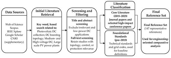
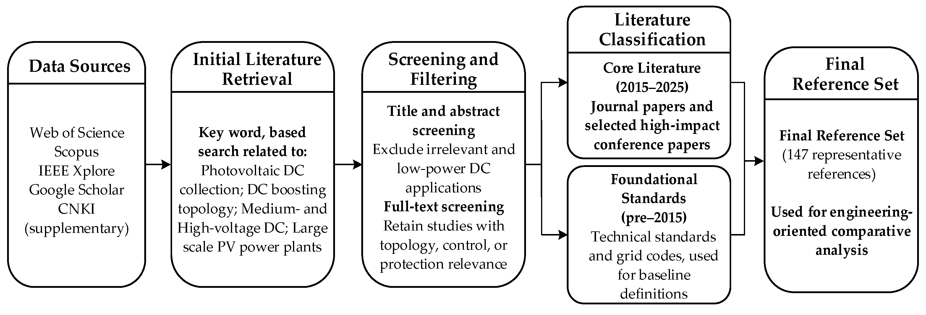
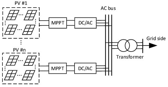
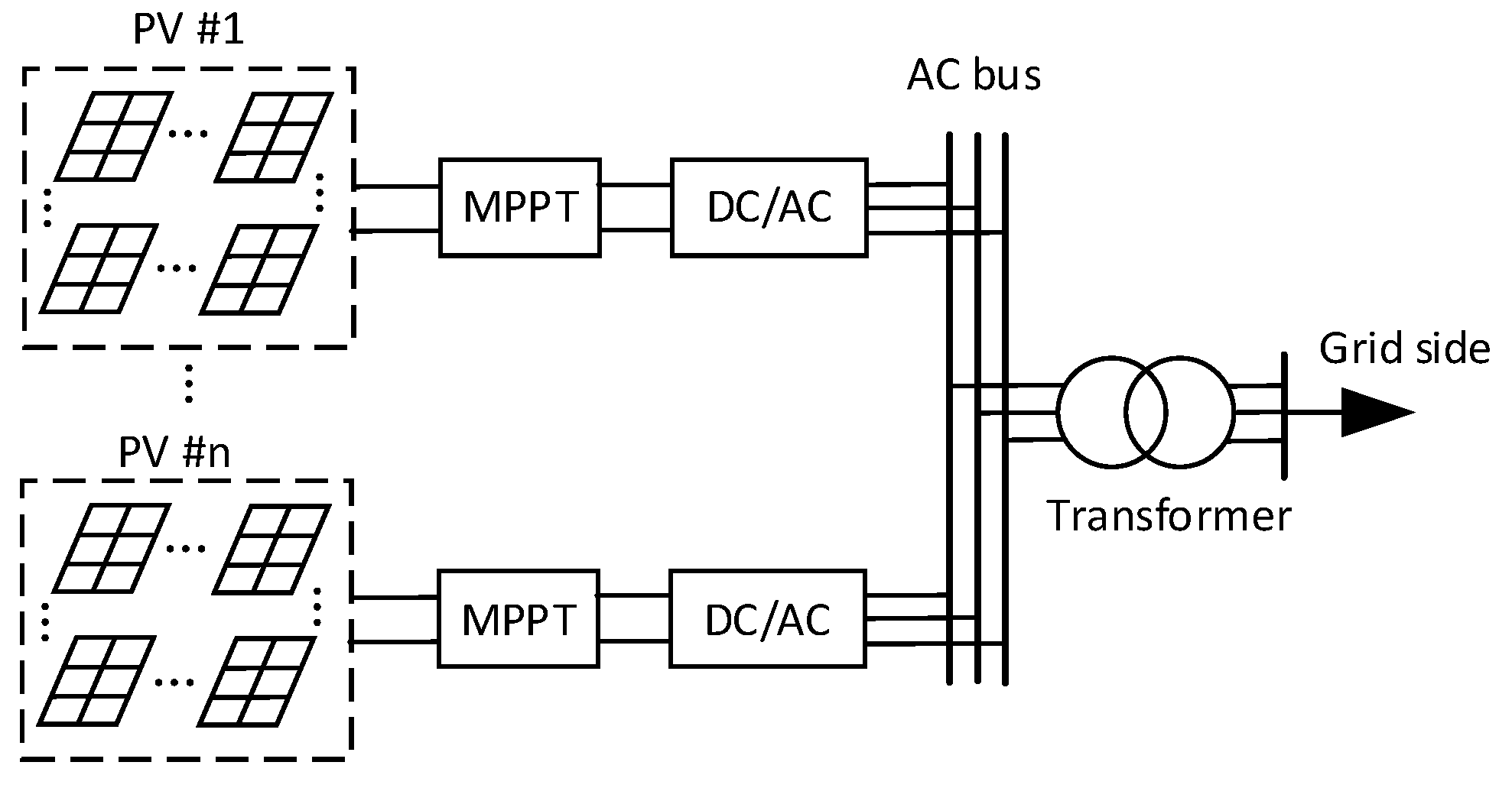
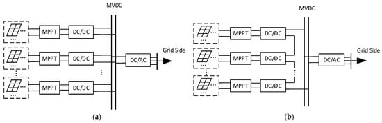
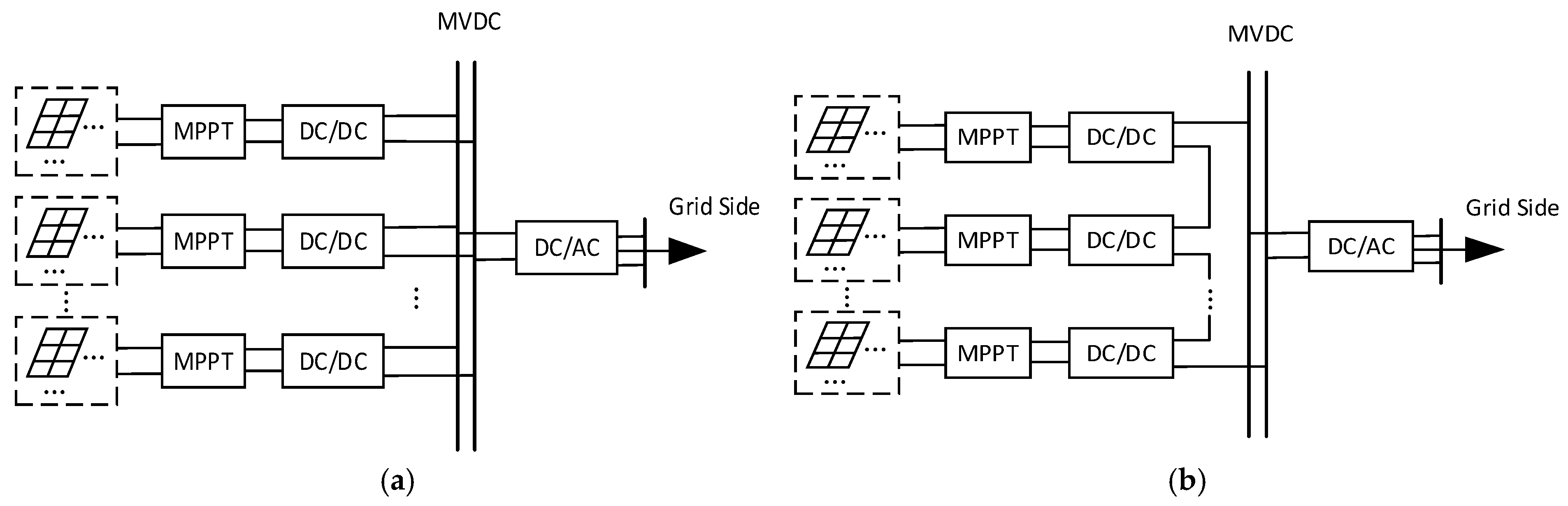
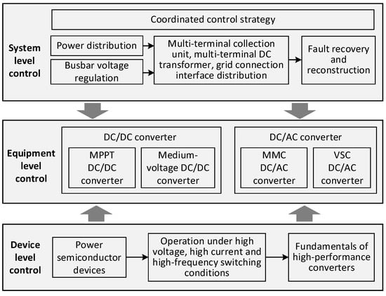
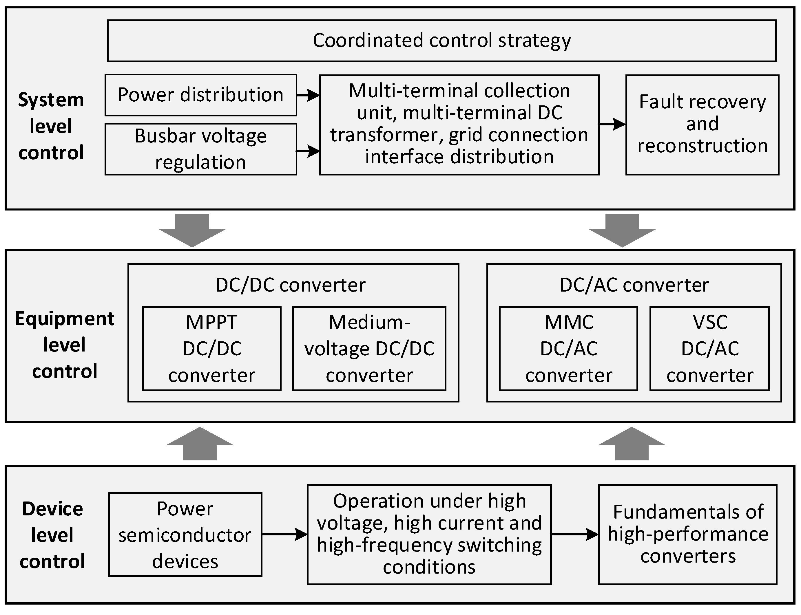
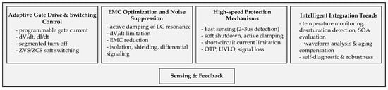
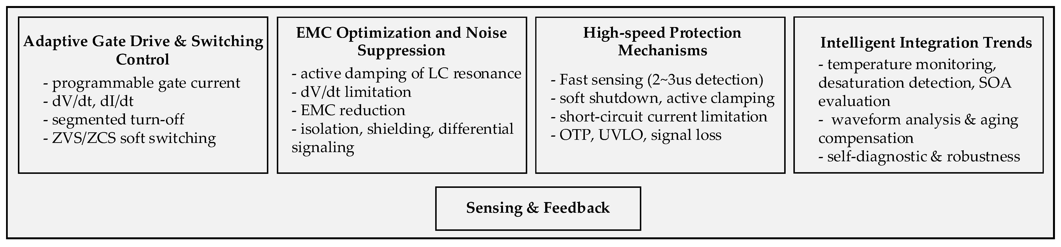
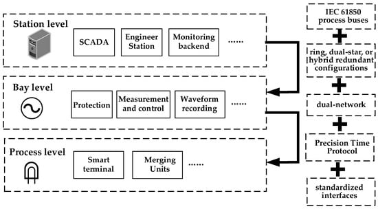
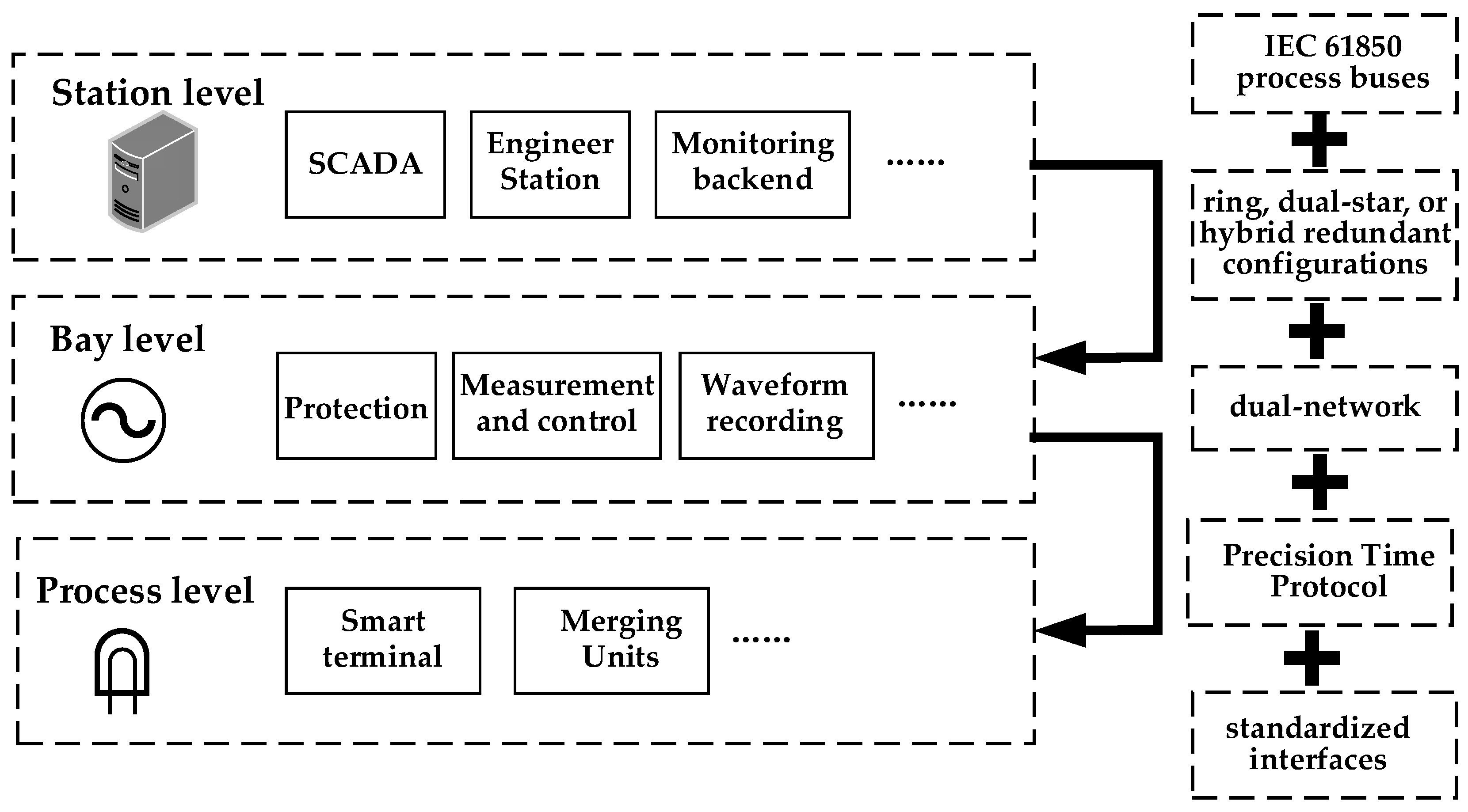

Disclaimer/Publisher’s Note: The statements, opinions and data contained in all publications are solely those of the individual author(s) and contributor(s) and not of MDPI and/or the editor(s). MDPI and/or the editor(s) disclaim responsibility for any injury to people or property resulting from any ideas, methods, instructions or products referred to in the content. |
© 2026 by the authors. Licensee MDPI, Basel, Switzerland. This article is an open access article distributed under the terms and conditions of the Creative Commons Attribution (CC BY) license.