


Abstract
The energy-efficient renovation of historic buildings requires solutions that improve thermal performance while preserving their architectural character. This study investigates the influence of architectural detail geometry on the thermal performance of historic masonry walls using a case study of the historic psychiatric hospital complex in Rybnik, Poland. Four characteristic architectural details, including cornices, brick projections, a semicircular arch, and a reinforced-concrete cornice, were analysed. For each detail, four construction variants were considered, taking into account different wall thicknesses and the presence or absence of an air cavity, resulting in sixteen two-dimensional numerical models. Thermal analyses were performed using the THERM 7.6 software based on the finite element method. The temperature distribution and selected thermal parameters were used to assess the effect of detail geometry on local thermal conditions. The results indicate that architectural details can significantly modify the local temperature field and surface temperature, while their influence on global thermal parameters may be less pronounced. The analysed cases demonstrate that the actual geometry of preserved architectural details should be considered in the thermal assessment of historic masonry walls, particularly when planning energy-efficiency improvements that require the preservation of existing façades.
1. Introduction
Historic buildings constitute an important part of the existing building stock and, in many cases, remain in use. Improving their energy efficiency is an important element in reducing energy consumption and improving user conditions; however, retrofit measures must simultaneously take into account energy requirements and the historical and architectural values of the building [1,2,3,4,5]. Review studies indicate that the energy retrofit of historic buildings is a complex process that requires simultaneous consideration of energy performance, user comfort, the condition of the existing building fabric, and heritage conservation requirements [1,2,3,4]. According to guidelines concerning the improvement of the energy performance of historic buildings, the selection of appropriate solutions should be preceded by an assessment, analysis, and documentation of the existing building, as well as an evaluation of the impact of the planned measures on the elements that determine its character [5].
In the case of historic façades, the application of standard external insulation may be limited due to the need to preserve their original appearance and architectural values. The application of insulation on the external side of a wall may alter the appearance of the façade and result in the loss of part of its historic character [6]. Internal insulation is therefore one possible solution that allows the façade to be preserved, but at the same time changes the thermal and hygrothermal conditions within the existing masonry wall [7,8,9,10]. This issue is particularly relevant for historic masonry walls, whose construction, materials, and technical condition may differ significantly from those of contemporary building envelopes [7,8].
Studies concerning historic masonry building envelopes indicate the need for an individual assessment of the effects of applying internal insulation. Among other factors, changes in temperature distribution, hygrothermal conditions, and the potential occurrence of local hygrothermal disturbances are investigated [7,8,9,10,11]. Results obtained using both measurement and numerical methods indicate that the application of internal insulation can significantly alter the conditions within the existing building envelope [9,10,11]. In the case of historic brick walls, factors such as material properties, wall thickness and layer arrangement, climatic conditions, and the method of insulation installation are of particular importance [8,9,10,11]. It has also been indicated that solutions applied in such buildings should be assessed individually, as hygrothermal conditions may vary depending on the construction and location of the analysed wall section [9].
Particular importance should be attributed to areas where changes in the geometry or construction of the building envelope occur, as these may modify heat flow and local surface temperature. This applies, among others, to areas containing thermal bridges, junctions between building elements, and other local geometric changes. Studies concerning historic masonry envelopes have highlighted the importance of local hygrothermal disturbances that may occur at junctions and in areas with modified geometry [9,12]. Numerical methods, including two-dimensional heat-transfer models based on the finite element method, are used to analyse such phenomena and enable the assessment of temperature distribution and heat flow in areas with complex geometry [12,13].
In historic buildings, local geometric variations result not only from structural junctions but also from characteristic architectural details such as cornices, plinths, arches, pilasters, and lesenes [14,15]. These elements form an integral part of the historic architectural character of façades while also introducing local changes in the shape and thickness of the building envelope. From a thermal analysis perspective, they may affect the local heat-flow pattern and temperature distribution. Unlike standard simplified envelope models, actual architectural details require their geometry and the mutual arrangement of materials to be taken into account.
Previous studies have extensively addressed thermal bridges and local hygrothermal disturbances in historic masonry, particularly in relation to junctions between building components and the use of internal insulation [9,12,13]. These studies have demonstrated the importance of local heat-flow patterns, surface temperatures, and hygrothermal conditions at critical points of historic masonry envelopes. However, the analysed geometrical features are generally considered as thermal bridges or construction junctions within defined wall configurations, rather than as preserved architectural details whose actual geometry is an integral part of the historic façade. Therefore, the influence of the specific geometry of existing architectural details on local thermal conditions remains insufficiently addressed.
The subject of the study is the historic complex of the Clinical Psychiatric Hospital in Rybnik, Poland, whose origins date back to the late nineteenth century. The complex was opened in 1886 and initially comprised 18 buildings, including 7 patient pavilions; it was subsequently expanded over the following years [16,17,18]. The preserved complex represents an extensive pavilion-type development with a diverse architectural form and a rich range of historic façade solutions. The long-term use of the complex and the preservation of its historic building fabric make it a suitable case study for analysing issues related to improving the thermal performance of existing buildings while simultaneously preserving their architectural values.
The aim of this paper is to assess the influence of the geometry of selected architectural details on the thermal behaviour of historic masonry walls and to determine the significance of these elements in the context of energy-efficient retrofitting of historic buildings. Four characteristic details occurring within the hospital complex in Rybnik were analysed. Two-dimensional numerical models were developed using THERM 7.6, and the assessment was based on temperature distribution and selected thermal parameters of the analysed wall sections.
The novelty of the present study lies in the comparative assessment of the actual geometry of preserved architectural details occurring in an existing historic building complex and its influence on local thermal conditions. Unlike studies focused primarily on conventional thermal bridges, internally insulated historic masonry, or local hygrothermal disturbances at selected junctions, the present work considers architectural details as existing geometric features of the historic façade. Four characteristic details were analysed in sixteen two-dimensional numerical variants, allowing the influence of their geometry and construction on local temperature distributions, internal surface temperatures, and selected thermal parameters to be assessed under identical boundary conditions.
2. Materials and Methods
2.1. Object of the Study
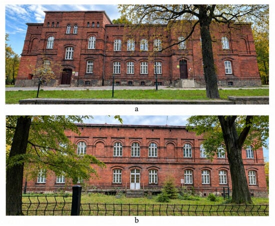
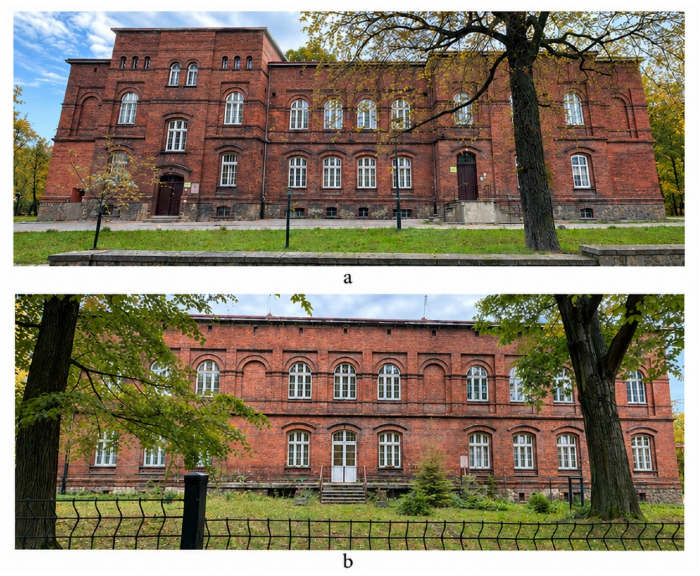
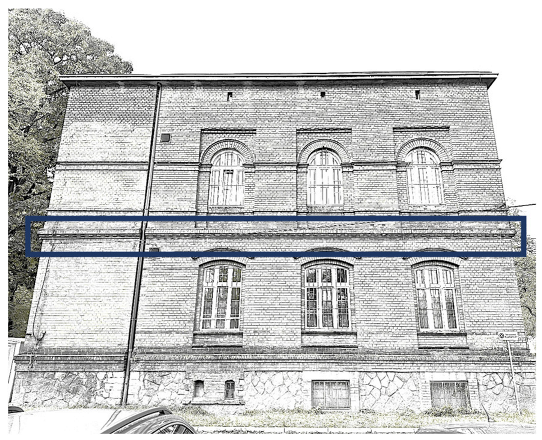
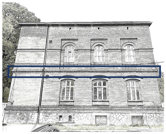
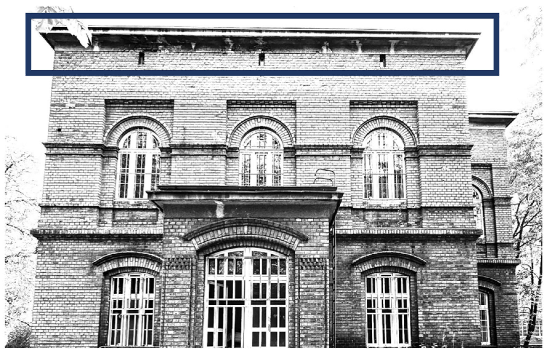
The subject of the study is the historic complex of the Clinical Psychiatric Hospital in Rybnik, whose origins date back to the late nineteenth century, shown in Figure 1.
Figure 1.
North (a) and south (b) elevations of the building under study.
The complex is characterized by preserved historic masonry buildings and a diverse architectural form of the individual structures. The façades feature details characteristic of the architecture of the period, including cornices, plinths, arches, pilasters, and lesenes. The diversity of their shapes and dimensions is an important aspect in analysing the influence of architectural detail geometry on the thermal properties of building envelopes.
The selection of the hospital complex in Rybnik as the subject of the study is based on its historic character, preserved architectural fabric, and continued use. The complex represents a historic building development in which improving energy efficiency must be considered while preserving the existing architectural form. For this reason, the complex provides a suitable case study for analysing the influence of architectural detail geometry on the local thermal conditions of historic masonry walls.
2.2. Assumptions
The study analysed characteristic architectural details adorning the façades of the hospital complex in Rybnik, constructed at the turn of the nineteenth and twentieth centuries. Selected elements in the form of cornices, arches, and intermediate forms of pilasters and lesenes were investigated [16,17,18].
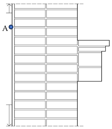
For the purpose of the analysis, four specific architectural details were selected and inventoried. The selected details were considered representative and characteristic of the architectural and constructional solutions occurring throughout the investigated hospital complex. The selection was based on an on-site inventory of the existing buildings, including photographic documentation and geometric measurements. The four details represent different types of architectural articulation observed in the complex, including cornices, projecting brick elements, a semicircular arch, and a reinforced-concrete cornice. The selection was intended to cover characteristic geometrical configurations occurring within the investigated complex rather than to constitute a statistically representative sample of historic masonry buildings in general. The details were documented photographically and subsequently developed as schematic representations and numerical models for analysis using THERM 7.6 [19].
The geometry of the analysed details was reconstructed primarily on the basis of the on-site inventory and measurements of the existing building fabric. The dimensions of the historic bricks were measured directly during the inventory survey and documented photographically. The reconstruction was additionally supported by photographic documentation and available historical and technical information. Because the available documentation did not provide complete information for all construction details, the identification and reconstruction of the original wall configurations required the combination of several sources of information.
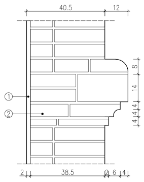
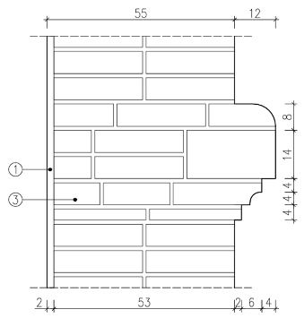
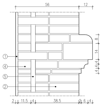
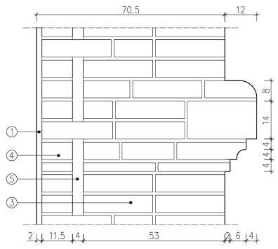
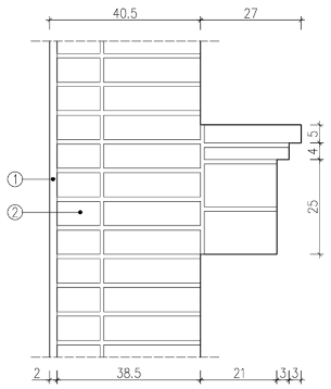
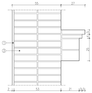
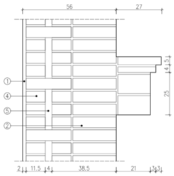
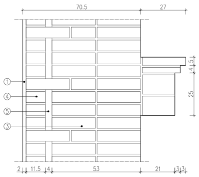
The study considered walls with varying thicknesses: 1.5-brick and 2-brick masonry walls, as well as variants with and without an air cavity. This approach allowed four construction variants to be developed for each of the analysed details, resulting in a total of sixteen cases subjected to further analysis. The adopted wall configurations were based on construction solutions identified in the investigated building and were therefore not introduced solely as hypothetical construction scenarios. In particular, the presence of an air cavity within the masonry wall was confirmed by exploratory openings carried out in the building. The cavity was treated as an intentional element of the historic wall construction, contributing to the thermal resistance of the wall. Where direct investigation did not provide complete information, the reconstruction was supplemented using literature describing historic building construction practices, including Ahnert and Krause [14]. Thus, the analysed variants represent construction solutions relevant to the investigated historic complex, with the literature used to supplement information that could not be established directly from the building.
Based on the inventory survey, solid brick dimensions of 26 × 12 × 6.5 cm were assumed. These dimensions were determined from measurements of the historic bricks identified in the investigated building; their unusual dimensions were also documented photographically. The mortar joint thicknesses were determined based on the available literature, with 10 mm vertical joints and 12 mm horizontal joints assumed. For the variants containing an air cavity, a cavity thickness of 4 cm was adopted. The cavity was modelled as an unventilated air layer. For implementation in THERM, the thermal conductivity assigned to the cavity region was calculated from the relationship λ = d/R, where d is the cavity thickness. For d = 0.04 m and R = 0.18 m2·K/W, the resulting value was λ ≈ 0.22 W/(m·K). This approach was applied consistently to all variants containing an air cavity, and all relevant numerical models were recalculated using the revised cavity representation.
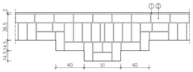
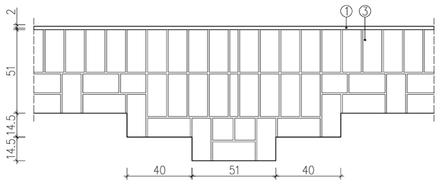
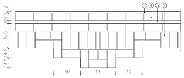
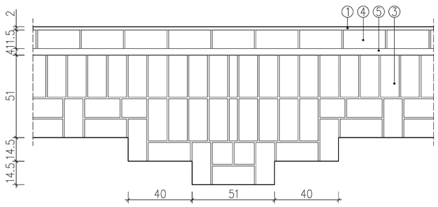
Table 1 presents a comprehensive summary of the materials used for Details 1–4, divided according to the analysed variants.
Table 1.
Summary of materials used for all analysed details.
The thermal conductivity values adopted for the building materials were based on technical literature and reference data used in Polish building physics. The values correspond to the assumed medium-moisture condition and were applied consistently across all numerical variants. They were not determined experimentally for samples taken from the investigated building. Direct sampling was not undertaken due to the conservation constraints associated with the protected historic building. The adopted moisture condition represents a calculation assumption and does not necessarily reflect the actual moisture state of the historic masonry.
2.3. Analysed Architectural Details
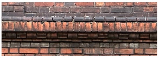
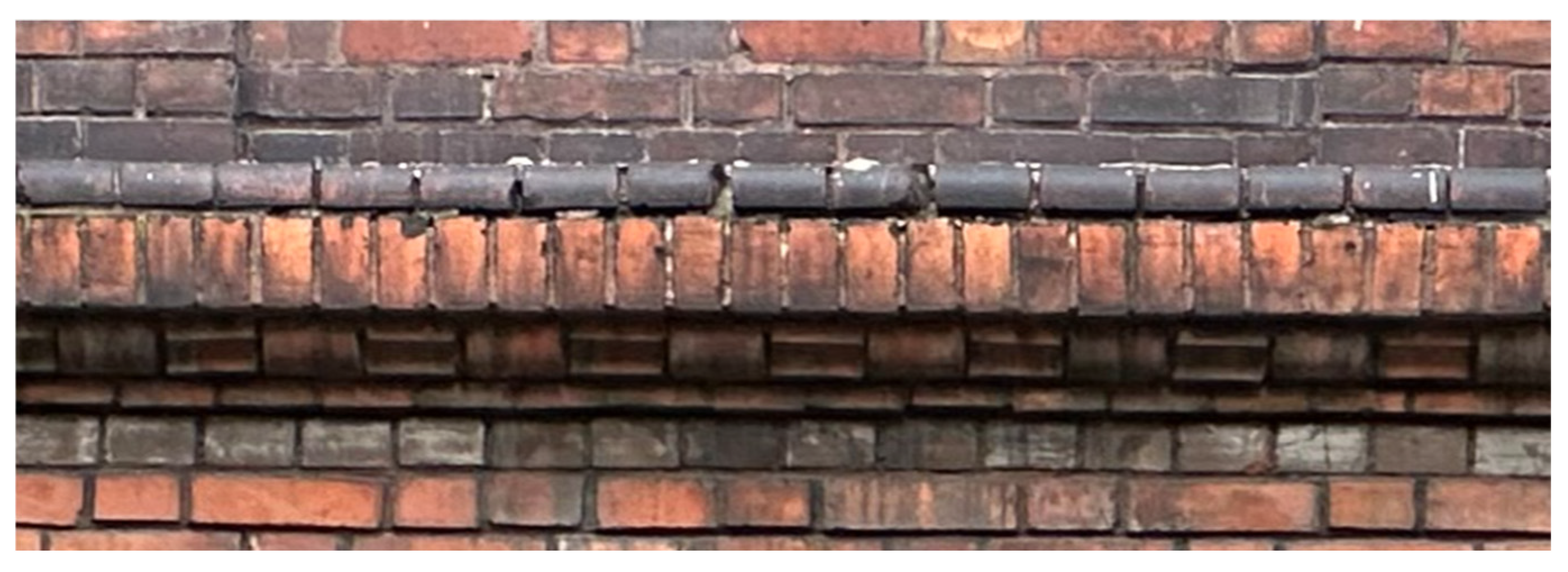
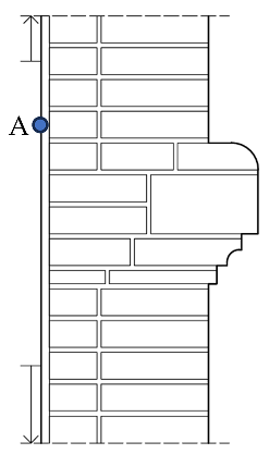
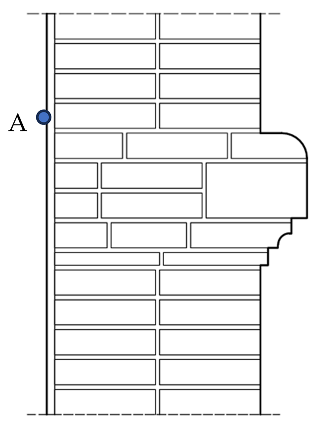
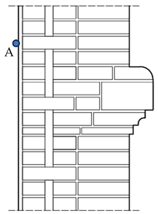
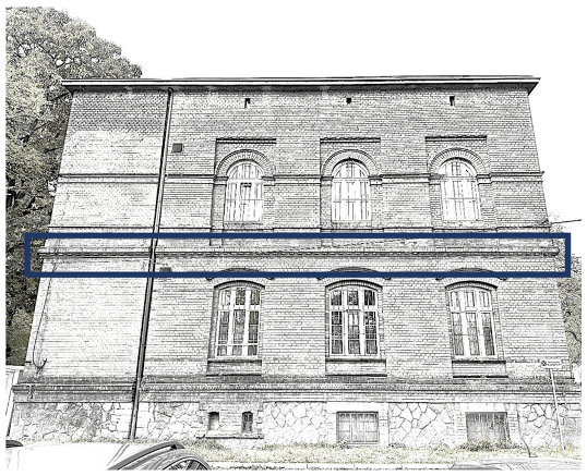
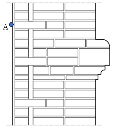
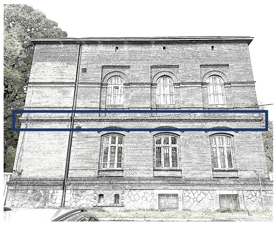
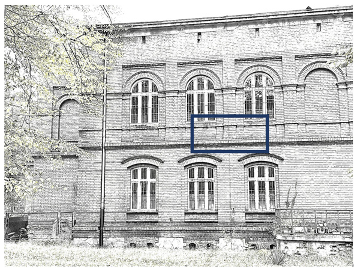
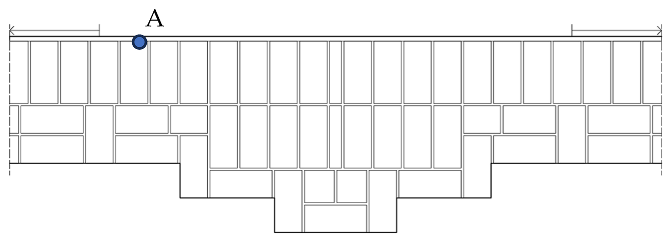
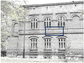
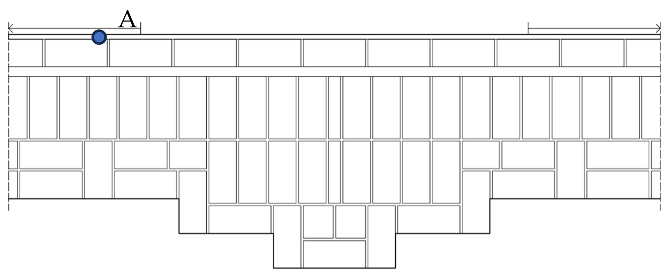
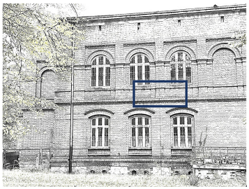
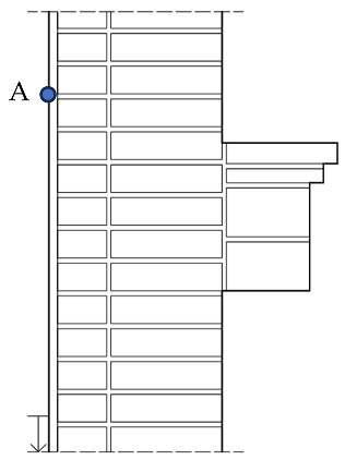
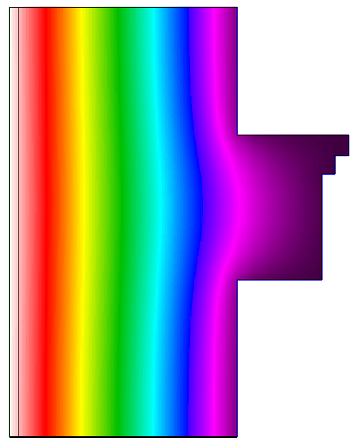
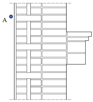
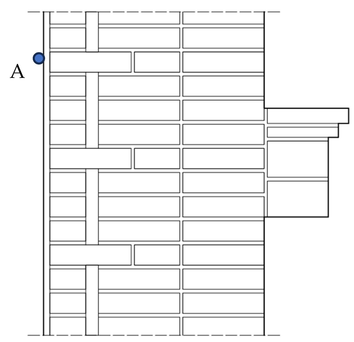
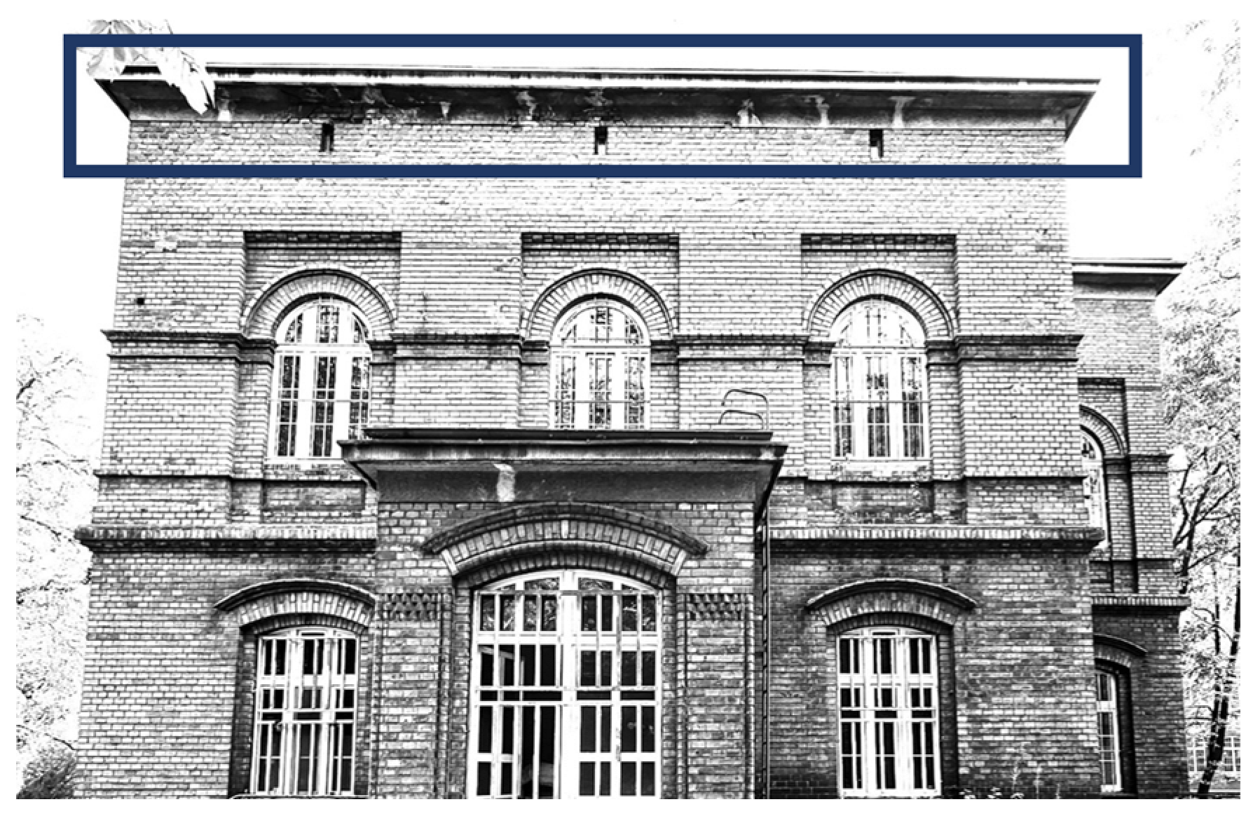
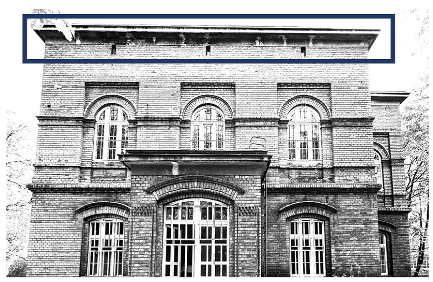
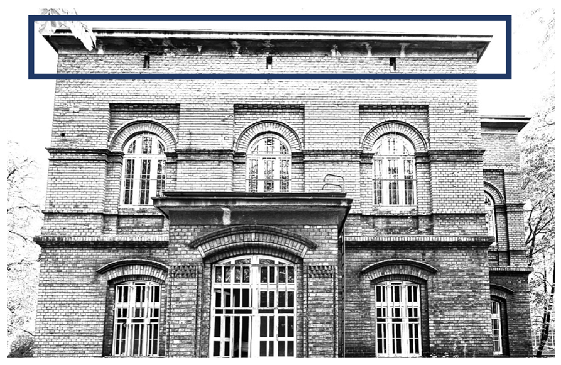
DETAIL No. 1 (Figure 2 and Table 2) is an unplastered brick cornice constructed using the brick corbelling technique, with a total height of 34 cm and a projection of 12 cm. The cornice consists of four layers. Three of these were formed by corbelling bricks laid flat, while one layer consists of bricks laid on edge. In addition to bricks of varying dimensions, specially shaped ceramic elements were also used.
Figure 2.
Photograph of Detail No. 1 taken at the hospital complex in Rybnik.
Table 2.
Summary of the four variants of Detail No. 1.
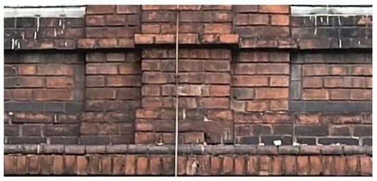
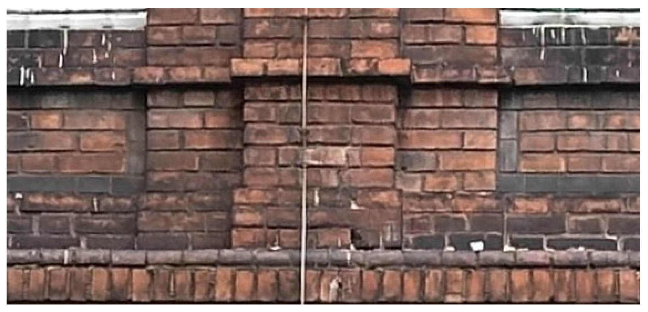
DETAIL NO. 2 (Figure 3 and Table 3) is a fragment of a vertical façade detail made of unplastered brick, formed as a wall projection combining the characteristics of a pilaster and a lesene. It constitutes an integral thickening of the brick wall, constructed simultaneously with the wall itself, with its form achieved by the gradual projection of successive brick courses. The element has a base but no capital. It has a tripartite, two-step configuration: on the left and right sides, there are narrower strips, each 39.5 cm wide, projecting half a brick beyond the wall face. The central part, which is slightly wider and measures 51 cm in width, projects by an additional half brick.
Figure 3.
Photograph of Detail No. 2 taken at the hospital complex in Rybnik.
Table 3.
Summary of the four variants of Detail No. 2.
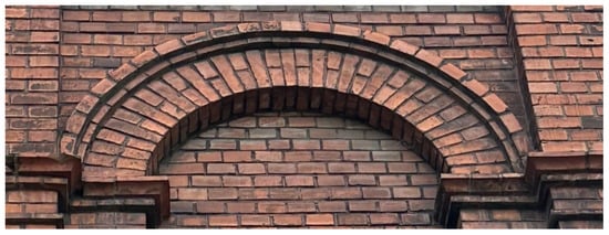
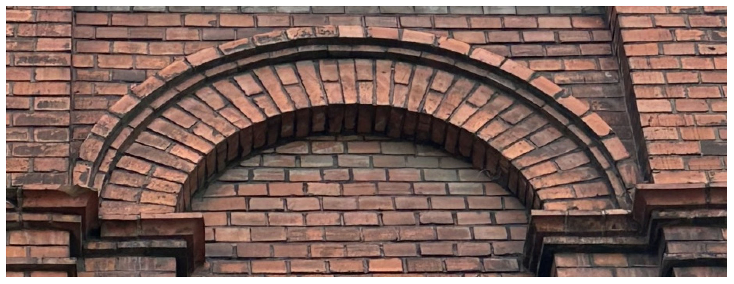
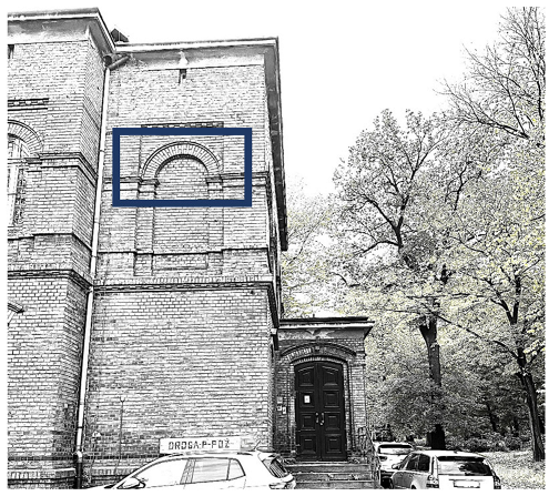
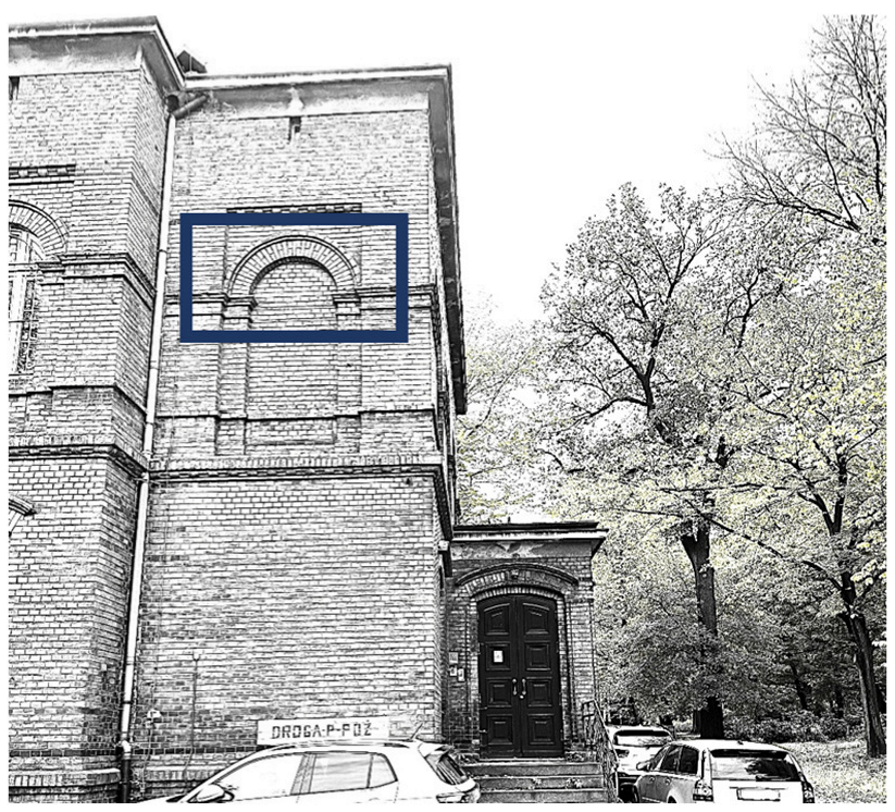
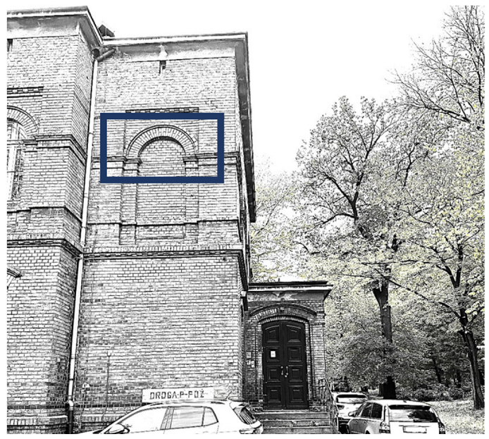
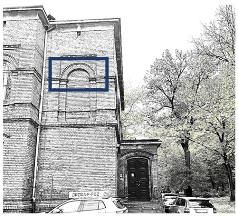
DETAIL NO. 3 (Figure 4 and Table 4) is a semicircular brick arch made of unplastered brick and integrated into the face of the brick wall. The load-bearing part of the arch consists of a ring of bricks arranged alternately with their headers and stretchers facing the arch surface. The upper part of the arch is covered with a configuration of shaped brick elements: directly above the ring, a thin, flattened element of small height was used, while above it, a second band made of a thicker element approximately two-thirds of a brick in height was arranged. Both bands form a clearly defined surround of the upper part of the arch, shaped in a stepped manner and projecting slightly beyond the structural part of the arch.
Figure 4.
Photograph of Detail No. 3 taken at the hospital complex in Rybnik.
Table 4.
Summary of the four variants of Detail No. 3.
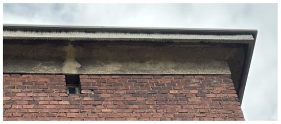
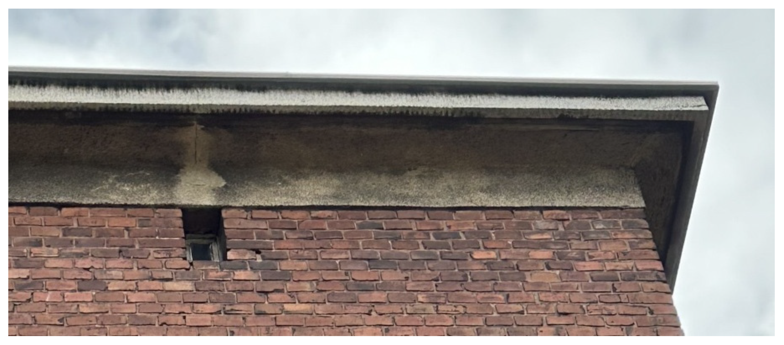
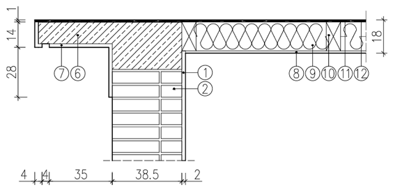
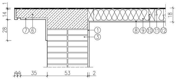
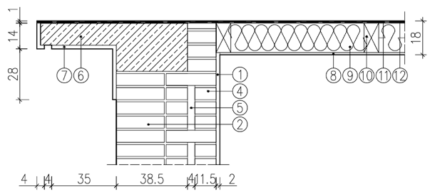
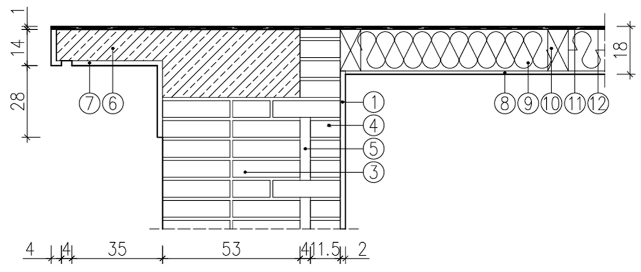
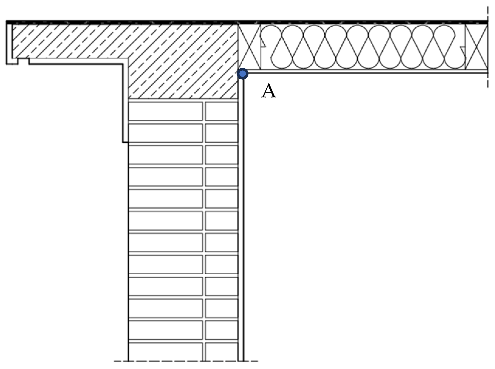
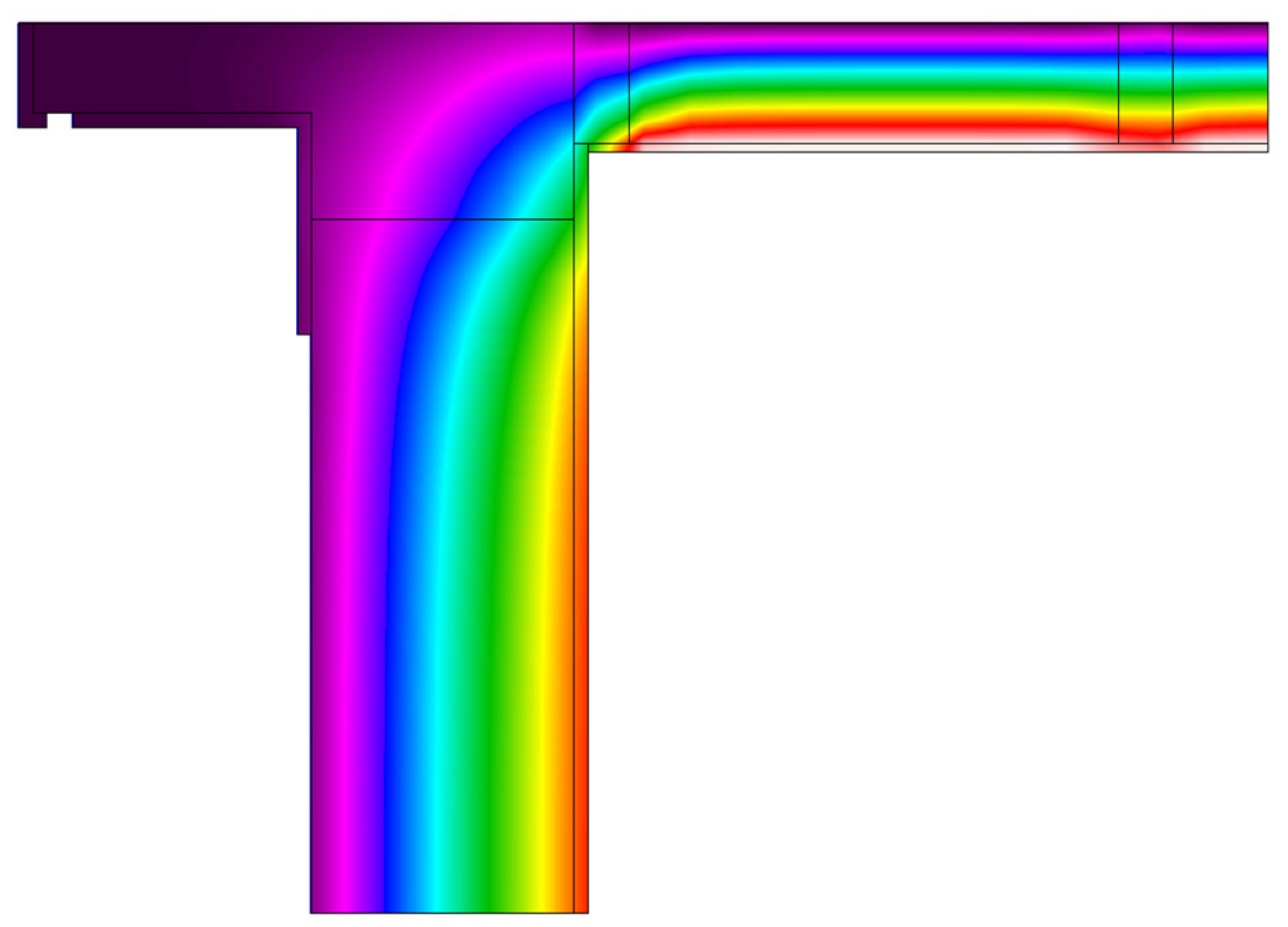
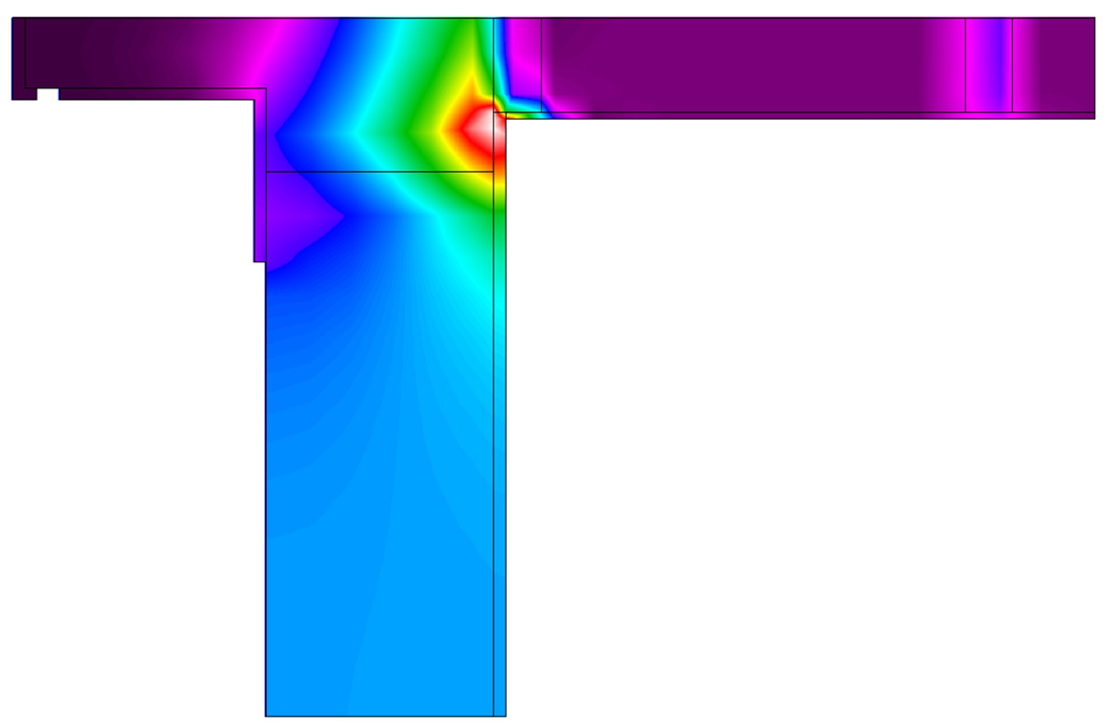
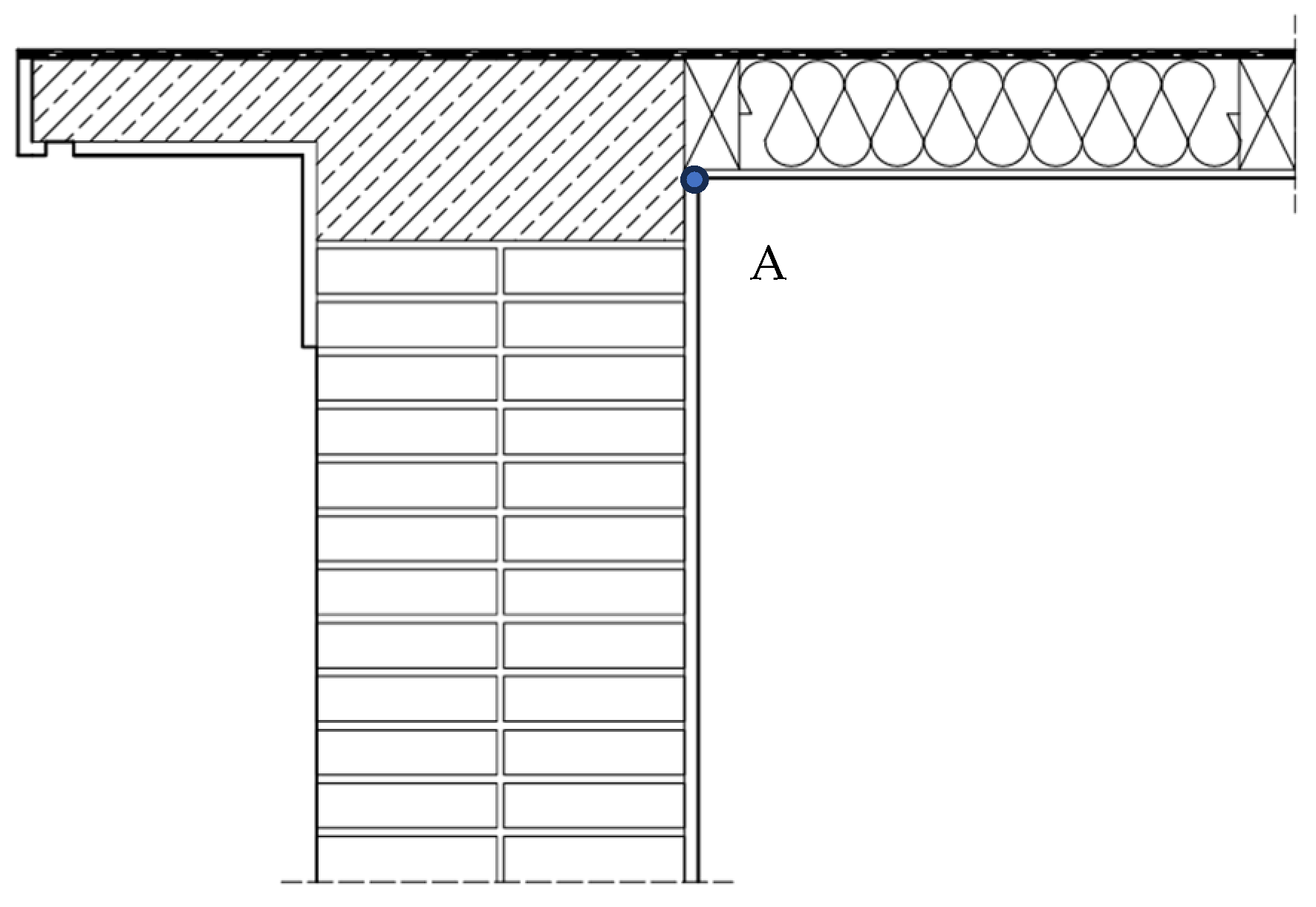
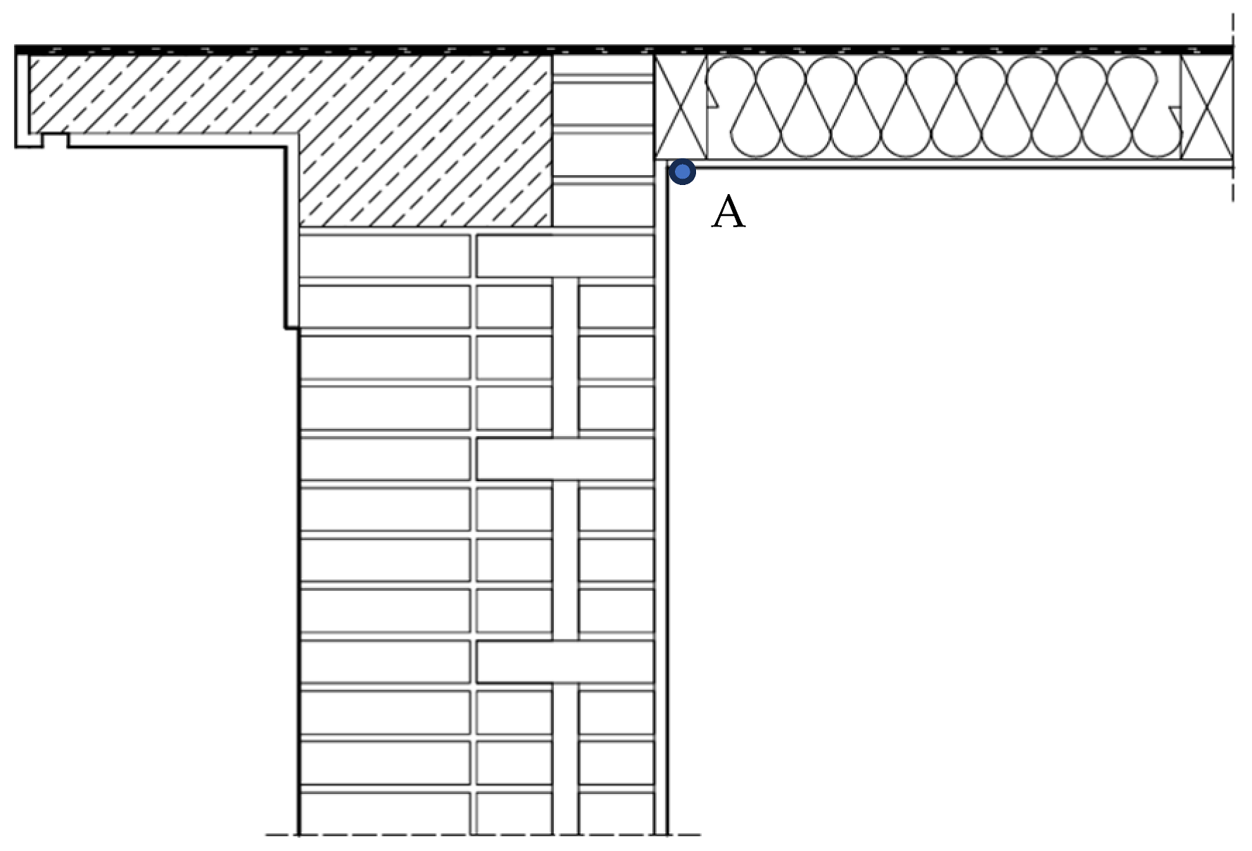
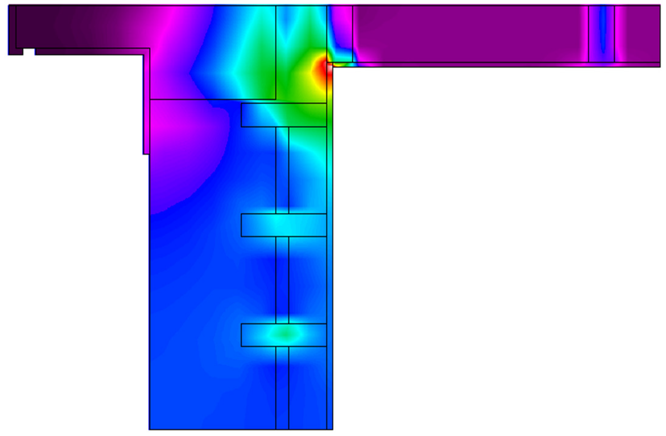
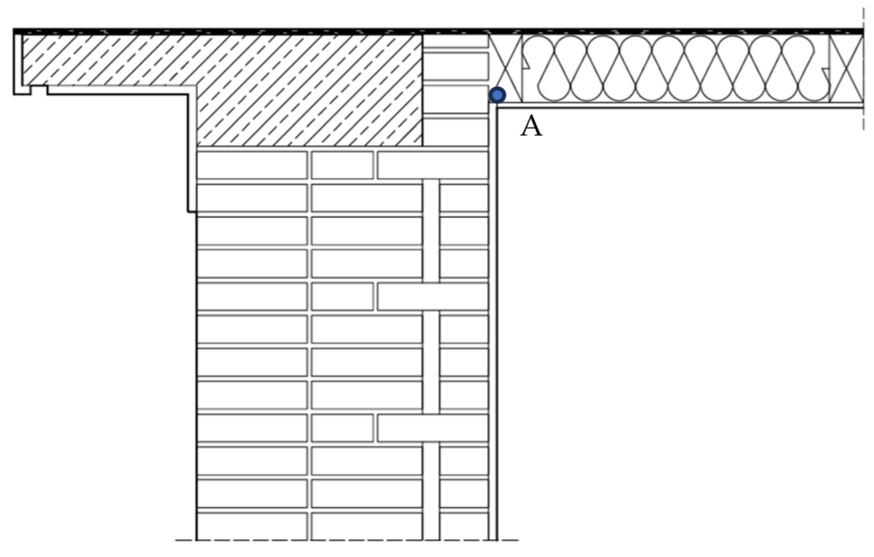
DETAIL NO. 4 (Figure 5 and Table 5) is a reinforced-concrete cornice crowning the brick wall. The cornice has a clearly defined projecting drip ledge with a height of 14 cm. The total projection of the cornice is 41 cm, while its overall height is 26 cm. The cornice is of monolithic construction, and its surface is finished with plaster, contrasting with the unplastered brick wall. On the interior side of the wall, there is a room topped by a flat roof with a timber structure and insulation. The finishing layer on the upper surface of the cornice and the roof consists of double-layer heat-welded roofing felt.
Figure 5.
Photograph of Detail No. 4 taken at the hospital complex in Rybnik.
Table 5.
Summary of the four variants of Detail No. 4.
2.4. Calculation Tools
The thermal analysis of the investigated details was performed using THERM 7.6, which enables two-dimensional heat-transfer calculations based on the finite element method (FEM) [19]. Based on the geometry of the analysed cross-section, the thermal properties of the materials, and the adopted boundary conditions, the temperature distribution and heat flow in the analysed building components were determined.
Assumptions and Calculation Conditions
The same calculation conditions were adopted for all analysed variants:
- Indoor air temperature: Ti = 20 °C;
- Outdoor air temperature: Te = −20 °C;
- Internal surface heat-transfer resistance: ;
- External surface heat-transfer resistance: ;
- Indoor relative humidity: .
Identical boundary conditions were applied to all models, enabling direct comparison of the results and assessment of the influence of the geometry of the analysed details on the thermal properties of the building components. The calculations were performed under steady-state heat-flow conditions, in accordance with the principles of detailed thermal bridge calculations specified in ISO 10211 [20].
The adopted indoor and outdoor temperatures were based on design conditions used for building heating calculations in Poland. According to PN-EN 12831 [21], the investigated location in Rybnik is situated in climatic zone III, for which the design outdoor temperature is −20 °C. The indoor temperature of 20 °C was adopted as a reference design temperature for normally occupied spaces. Thus, the applied boundary conditions represent a reference winter design condition with a temperature difference of 40 K, rather than a specific short-term weather event.
The same boundary conditions were applied consistently to all analysed variants to enable direct comparison of their thermal behaviour. The adopted indoor relative humidity of 55% was used as a reference condition for the assessment of internal surface thermal conditions.
The steady-state approach does not account for transient changes in outdoor temperature, solar radiation, thermal storage in the masonry, variations in indoor conditions, or time-dependent moisture transport and its influence on the thermal properties of the materials. The results should therefore be interpreted as a comparative assessment of the analysed historical construction variants under defined reference winter conditions.
For the mesh sensitivity assessment presented in Table 6, the QFM parameter (Quad Tree Mesh Parameter) was additionally varied from 5 to 8, while the Error setting and maximum number of iterations were kept constant. The mesh-refinement assessment was performed for Detail1, variant 3, selected because its wall arrangement is representative of the construction system recurring in the analysed variants. The same geometry, material properties, boundary conditions, and solver settings were maintained while the QFM parameter was varied.
Table 6.
Sensitivity of the calculated thermal parameters to the numerical settings.
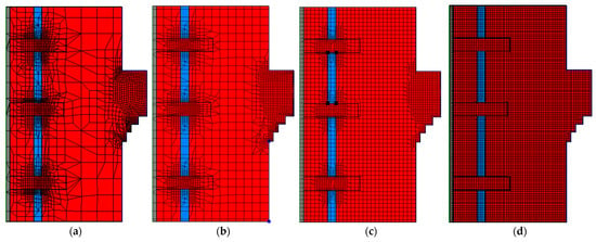
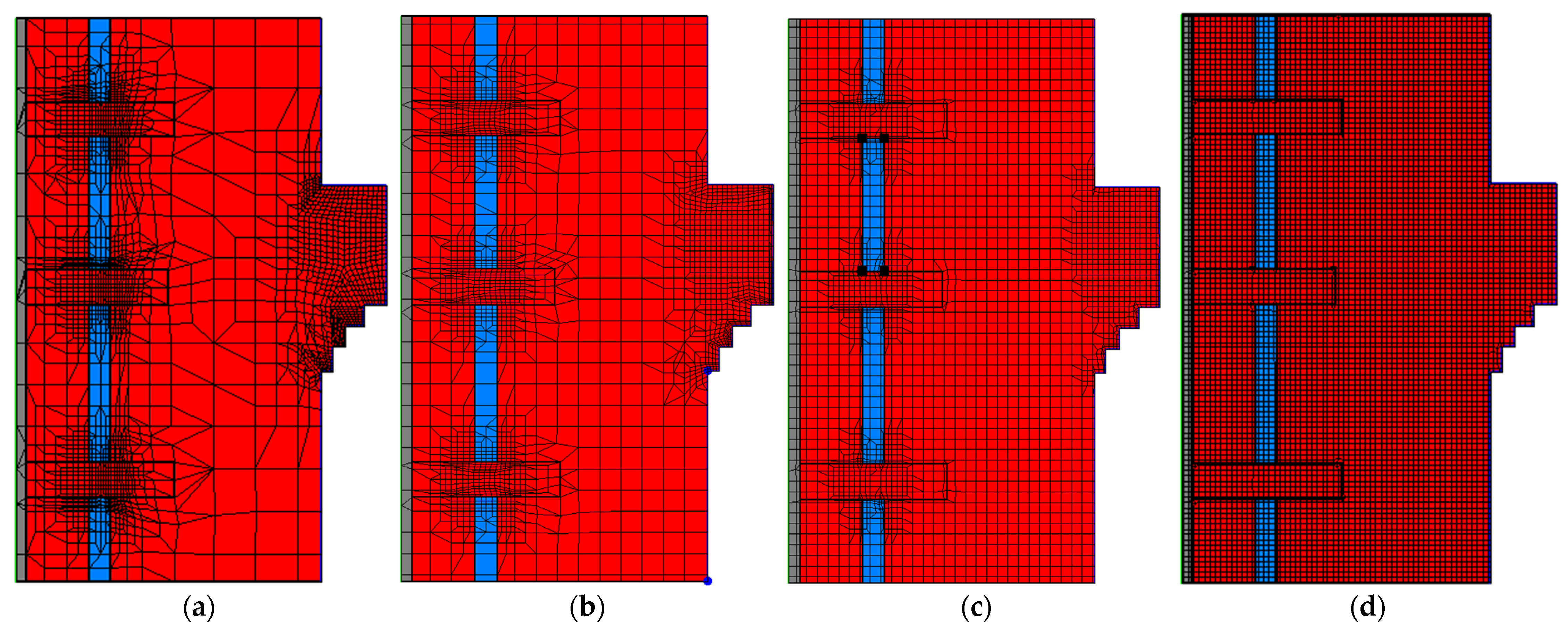
The Run Error Estimator option was enabled, with Maximum % Error Energy Norm set to 2% and Maximum Iterations set to 20 in the Mesh Control settings. In the Simulation settings, the solver convergence tolerance was set to 1 × 10⁻⁶, the Relaxation Parameter to 1, and Maximum Iterations to 25. Automatic relaxation adjustment was enabled, with an adjustment step of −0.01 (Figure 6).
Figure 6.
Finite element mesh (FEM) used in the analysed model, with local mesh refinement in the areas of connections and geometric discontinuities for Detail 1, Variant 3, (a) case 1, (b) case 2, (c) case 3, (d) case 4.
The sensitivity of the calculated thermal parameters to numerical settings was assessed using four mesh configurations (Table 6 and Table 7). The QFM parameter was increased from 5 to 8, while the Error setting (2%) and the maximum number of iterations (20) were kept constant. The number of finite elements increased from 2552 to 7359, and the number of temperature nodes increased from 2521 to 7187.
Table 7.
Changes in global and local thermal quantities between successive mesh configurations.
The global thermal quantities showed high numerical stability across the tested configurations. The heat flow rate varied from 41.3026 W to 41.3039 W, while the thermal transmittance ranged from 1.0660 to 1.0665 W/(m2·K). The relative differences between Cases 3 and 4 were approximately 0.0002% for the heat flow rate and 0.009% for the thermal transmittance.
The local thermal quantities exhibited a different pattern. Between Cases 1 and 2, the minimum internal surface temperature increased from 13.7 °C to 14.7 °C, and the internal surface temperature factor increased from 0.8425 to 0.8675. Between Cases 2, 3 and 4, both local quantities remained unchanged at the reported precision, with a minimum surface temperature of 14.7 °C and a temperature factor of 0.8675. This indicates that the local results were stable across the three finer mesh configurations at the precision reported in Table 6.
The results demonstrate that the heat flow rate and thermal transmittance were stable across all four tested configurations, whereas the local surface quantities required a finer mesh to reach stable reported values. The assessment is limited to the selected configuration and the tested QFM settings; therefore, it does not establish mesh independence for all sixteen analysed variants.
For this assessment, the following study-specific convergence criteria were adopted: a relative change of no more than 1% for the heat flow rate and thermal transmittance, an absolute change of no more than 0.1 K for the minimum internal surface temperature, and an absolute change of no more than 0.005 for the internal surface temperature factor. The temperature criterion was selected with reference to the 0.1 K accuracy criterion used in the EN ISO 10211 benchmark test described below; the criteria for the other quantities were adopted for the present comparative assessment. These thresholds are used to evaluate the tested configurations and are not presented as universal mesh-convergence limits prescribed by the standard.
The numerical procedure was additionally validated using Benchmark Test No. 1 specified in Annex A of EN ISO 10211. The benchmark considers heat transfer through one half of a rectangular column with prescribed surface temperatures. The analytical solution is provided at 28 equally spaced nodal points. According to EN ISO 10211, the difference between the reference values and the numerical results should not exceed 0.1 K.
The numerical results obtained using THERM differed from the analytical reference values by no more than 0.1 K. At three mesh nodes, the numerical temperatures were 0.1 K lower than the corresponding reference values, while at all remaining nodes the calculated temperatures were identical to the reference solution. Thus, the results satisfied the acceptance criterion specified in EN ISO 10211.
The benchmark test confirmed the suitability of the numerical procedure implemented in THERM for the two-dimensional steady-state heat transfer analyses performed in this study.
Direct experimental validation based on in situ measurements was not available for the analysed models. Therefore, the reliability of the adopted numerical modelling procedure was assessed using the benchmark test specified in Annex A of EN ISO 10211, together with the mesh sensitivity assessment described above.
Numerical Modelling
For each case, a two-dimensional geometric model was developed, comprising a section of the wall together with the analysed architectural detail. The models represented the actual geometry of the investigated solutions occurring in the hospital complex in Rybnik.
The models included:
- The geometry of the analysed detail;
- The arrangement and thickness of the building component layers;
- The thermal properties of the materials used;
- Heat-transfer conditions at the surfaces of the building component;
- Indoor and outdoor temperatures.
For each variant, the temperature and heat-flow distributions were determined. The use of identical calculation parameters enabled comparison of the individual variants in terms of the influence of their geometry on the thermal behaviour of the building component.
Calculated Quantities
Based on the calculations performed, the following quantities were determined:
- Temperature distribution in the analysed cross-section;
- Distribution of isotherms;
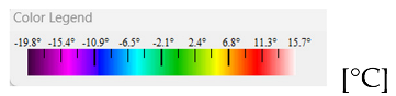
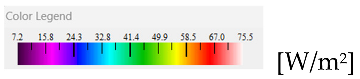
- Heat flux density [W/m2];
- Heat flow rate [W];
- Minimum internal surface temperature [°C];
- Thermal transmittance [W/(m2K)];
- Thermal coupling coefficient [W/(m·K)];
- Linear thermal transmittance [W/(m·K)];
- Temperature factor [-].
Calculation Relationships
Thermal transmittance [22]:
where
—thermal transmittance [W/(m2K)];
—total thermal resistance of the building component [m2K/W].
Thermal coupling coefficient [20]:
where
—thermal coupling coefficient [W/(m·K)];
—heat flow rate per unit length of the analysed model [W/m];
—indoor air temperature [°C];
—outdoor air temperature [°C].
Linear thermal transmittance [20]:
where
—linear thermal transmittance [W/(m·K)];
—thermal coupling coefficient [W/(m·K)];
—thermal transmittance of the -th one-dimensional section of the building component [W/(m2K)];
—length of the -th section of the building component [m].
In accordance with ISO 10211, the reference configuration for the calculation of ψe was defined on the basis of the corresponding one-dimensional building-component sections adjacent to the analysed junction. The reference lengths lj were taken along the respective building-component sections represented in the two-dimensional model. Thus, ψe represents the difference between the calculated two-dimensional heat flow and the heat flow corresponding to the adopted one-dimensional reference configuration. Positive values indicate an increase in heat flow relative to the reference configuration, whereas negative values indicate a lower heat flow than that of the reference configuration.
The sign of ψe should therefore be interpreted in relation to the adopted reference configuration and should not be considered a direct indicator of local internal surface-temperature conditions. The assessment of local thermal conditions was performed separately using the minimum internal surface temperature and the internal surface temperature factor fRsi.
Internal surface temperature factor [23]:
where
—internal surface temperature factor [-];
—minimum internal surface temperature at the critical location [°C];
—indoor air temperature [°C];
—outdoor air temperature [°C].
The critical location was defined as the point on the internal surface of the building component at which the lowest surface temperature occurred. The values of and were used to assess the local thermal conditions within the analysed details.
3. Results
The calculated thermal parameters for all sixteen analysed variants are summarised in Table 8. The table provides a consolidated comparison of the thermal transmittance, heat flow rate, thermal coupling coefficient, linear thermal transmittance, minimum internal surface temperature, and internal surface temperature factor for all analysed cases.
Table 8.
Consolidated comparison of the calculated thermal parameters for all analysed variants.
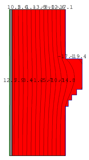
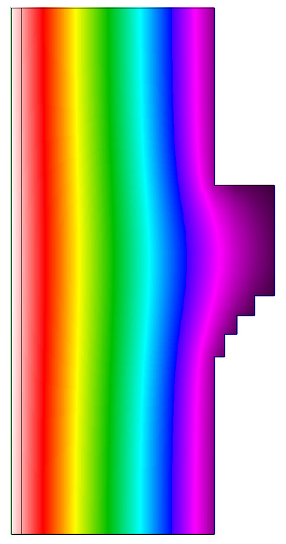
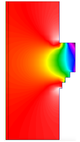
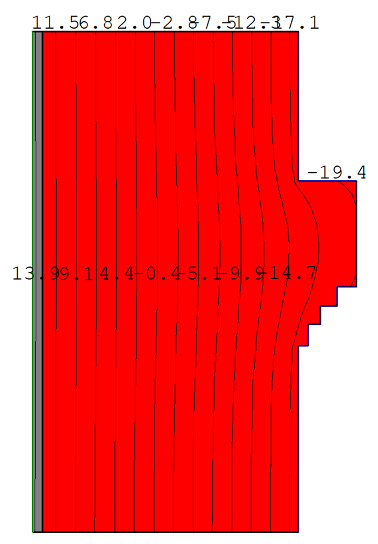
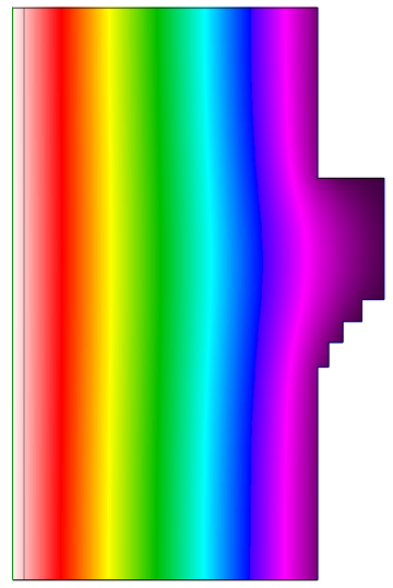
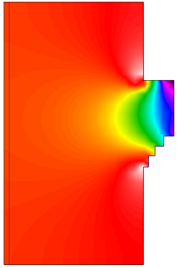
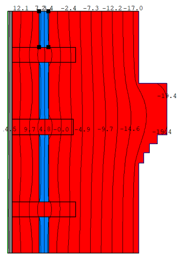
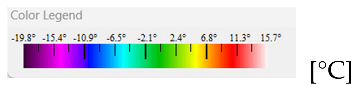
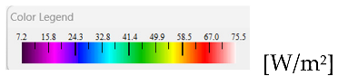
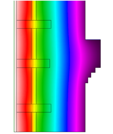
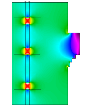
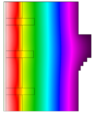
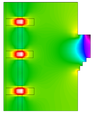
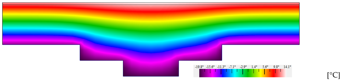
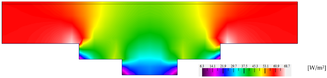
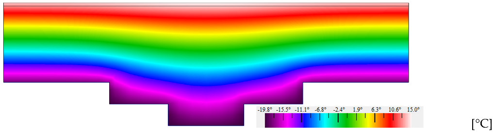
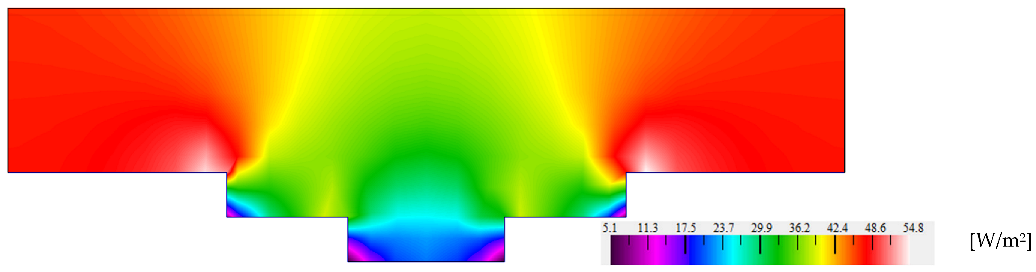
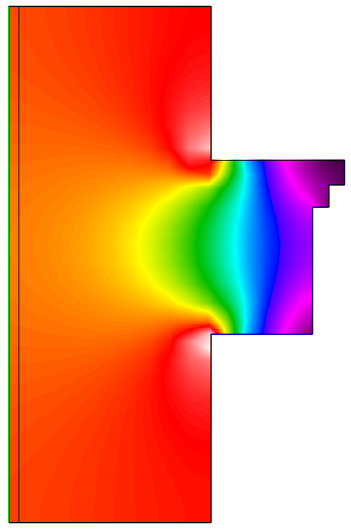
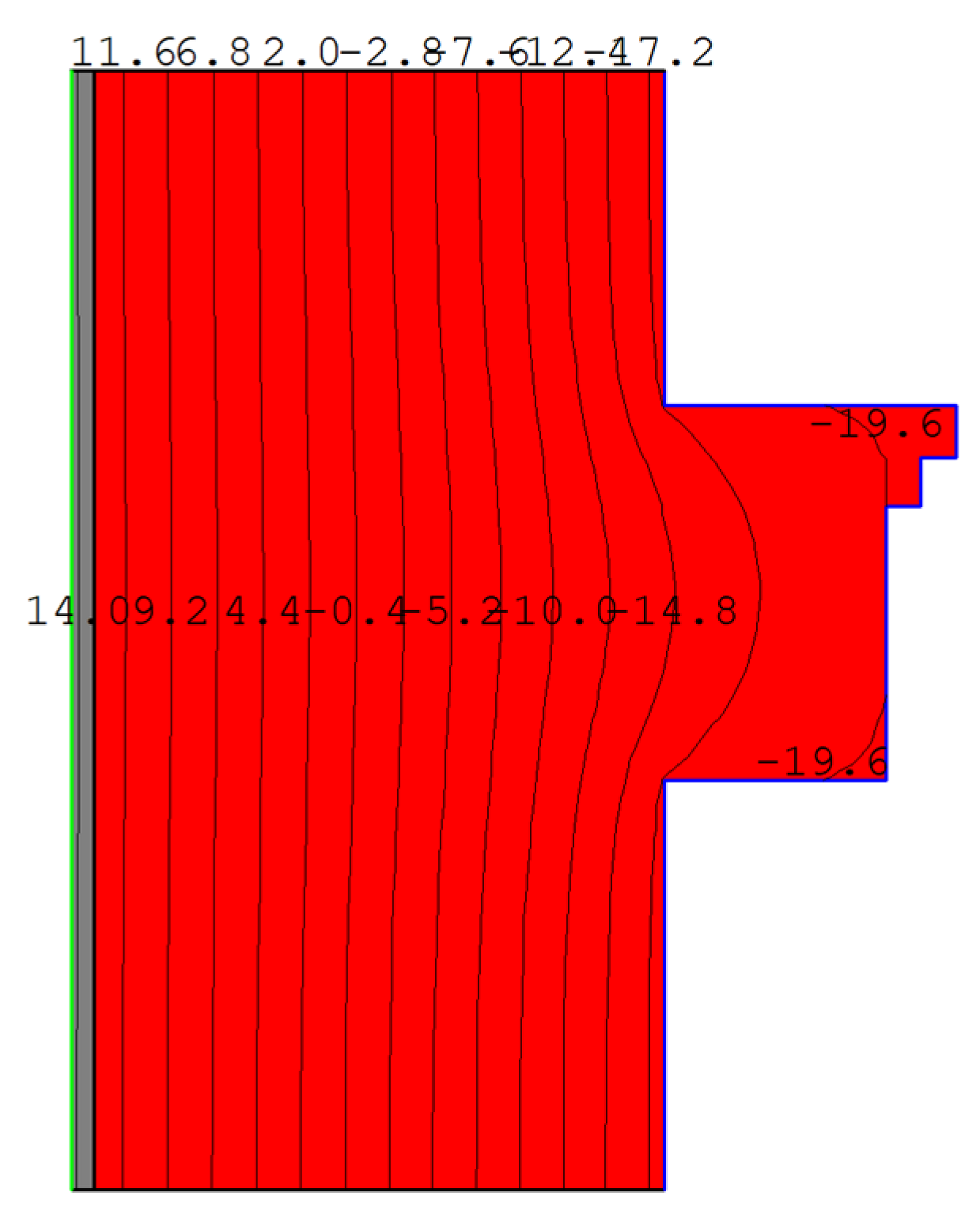
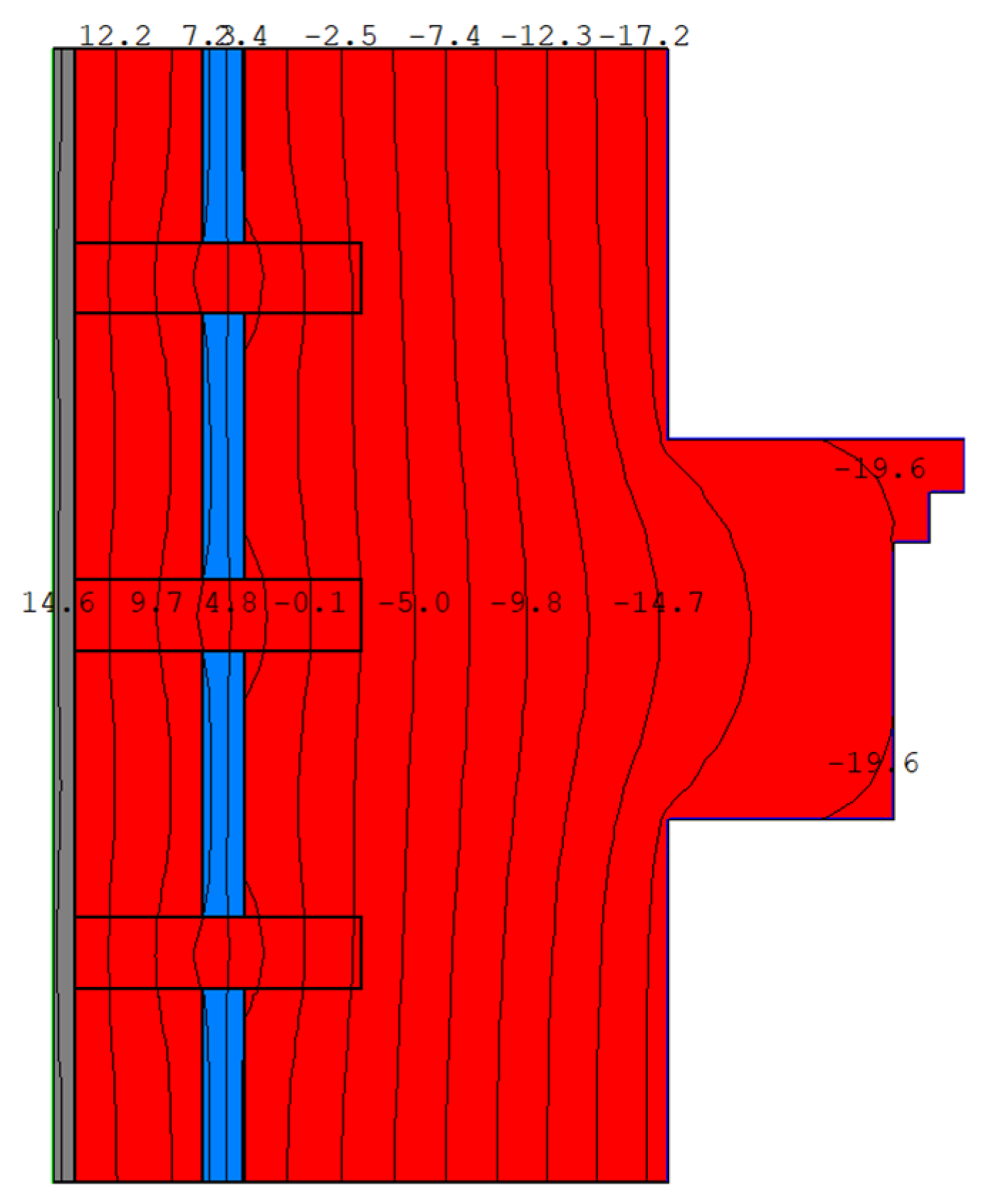
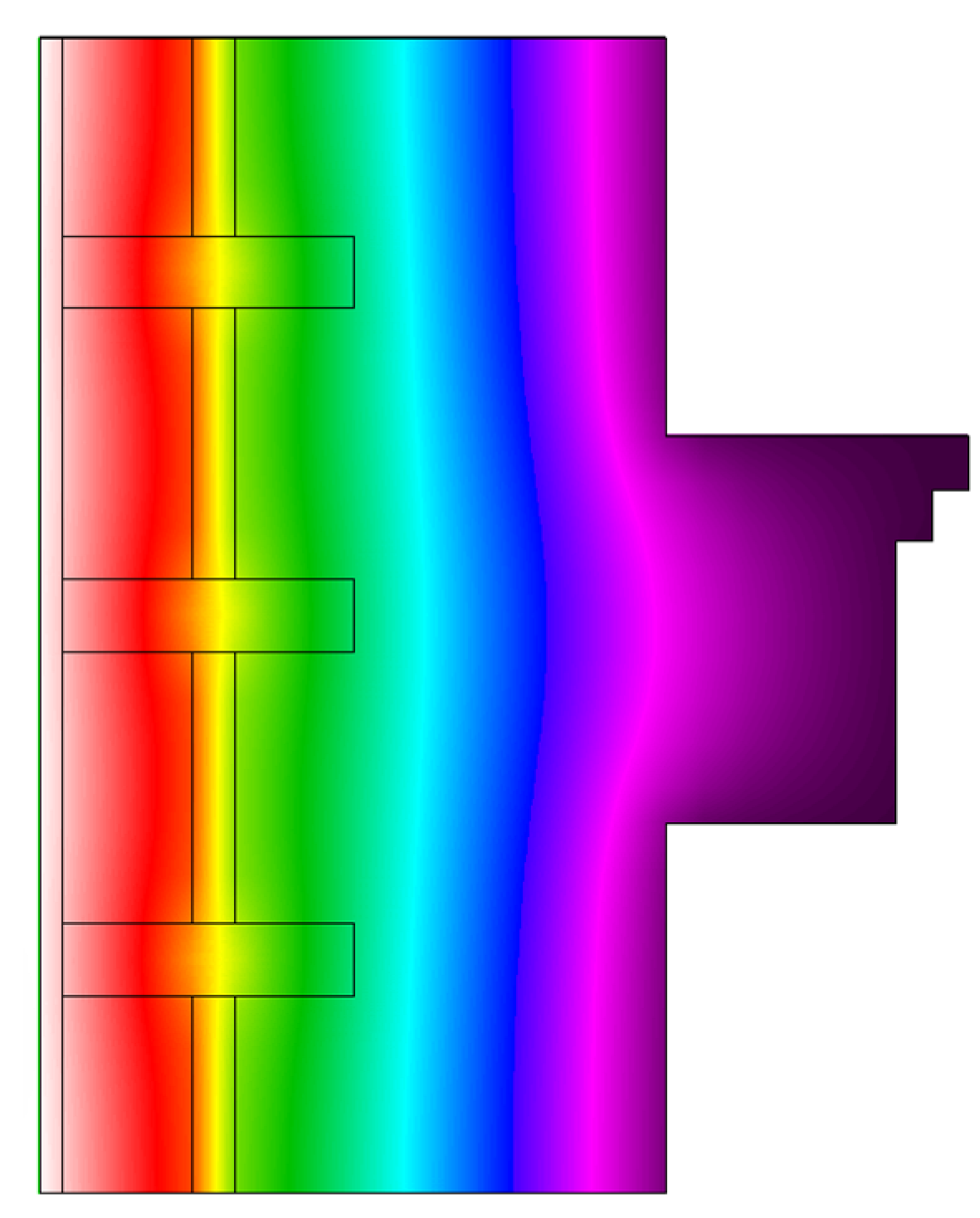
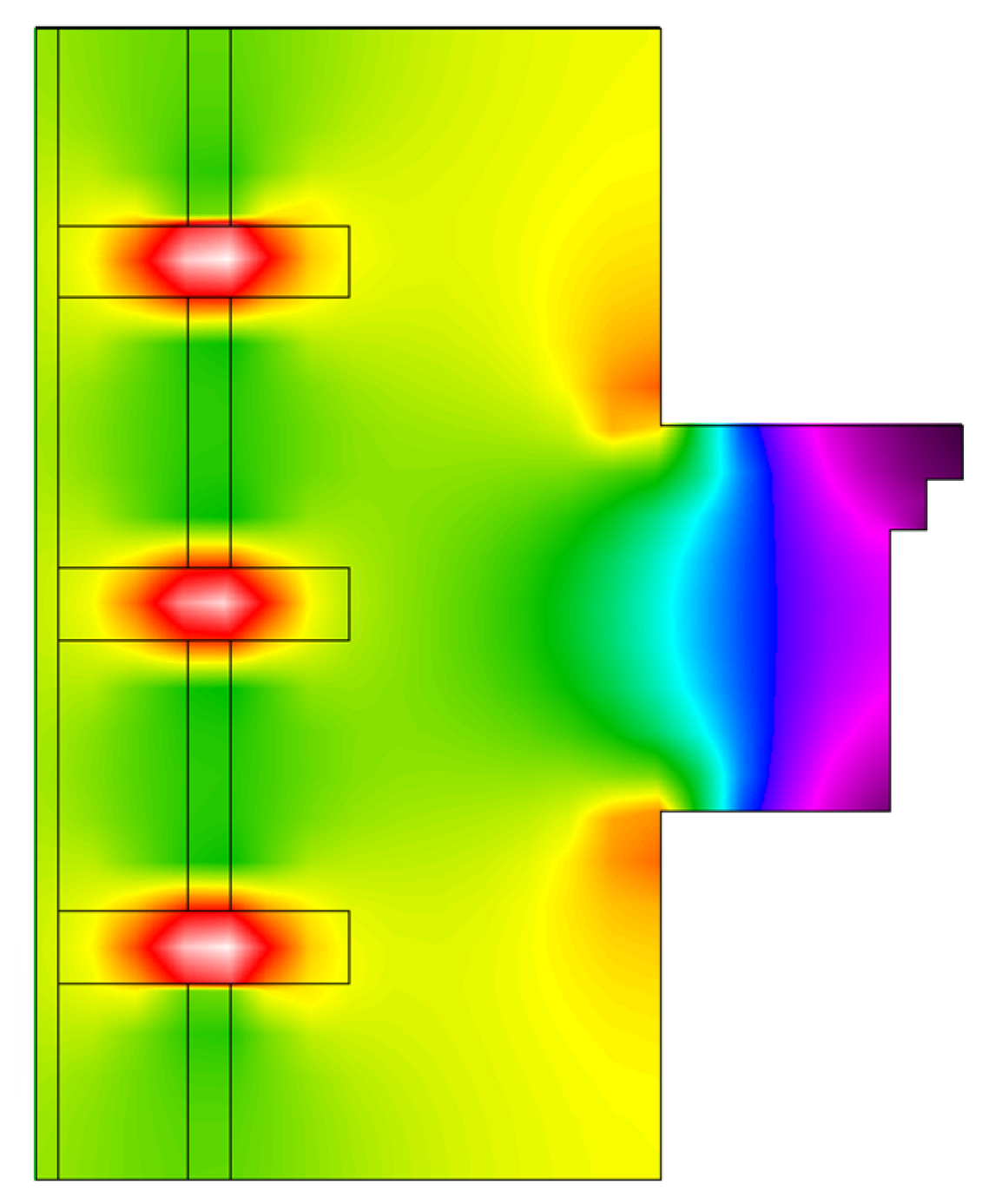
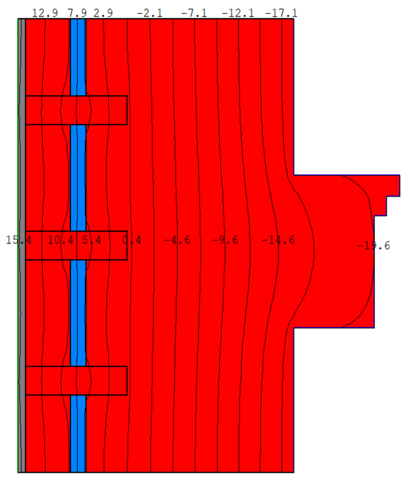
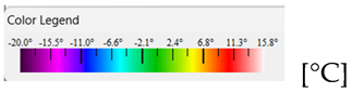
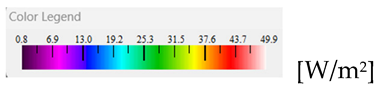
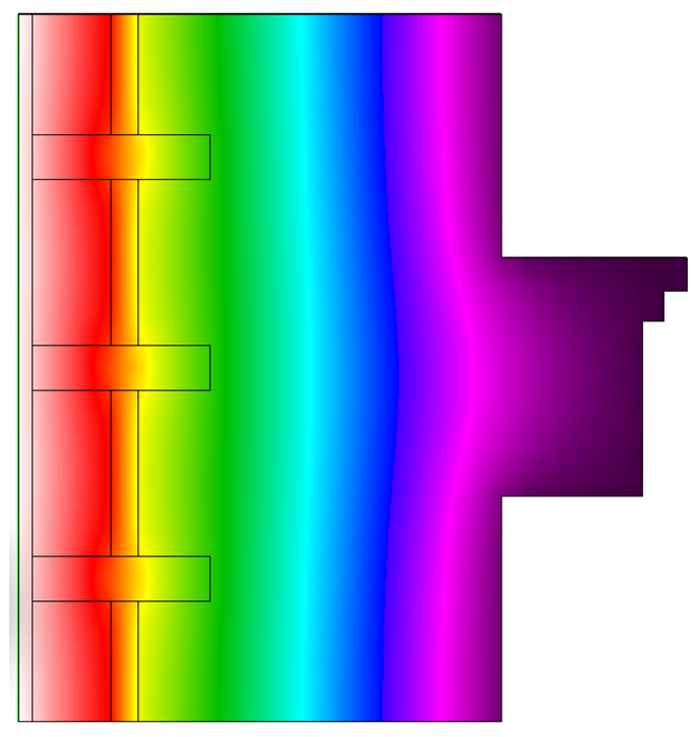
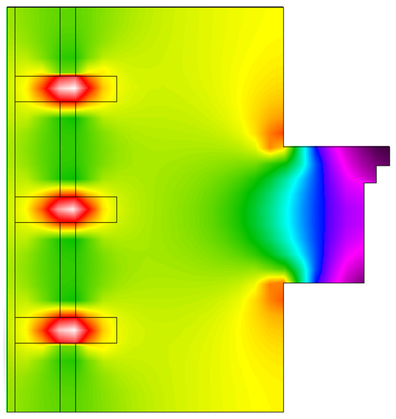
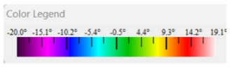
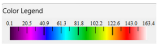
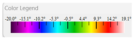
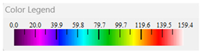
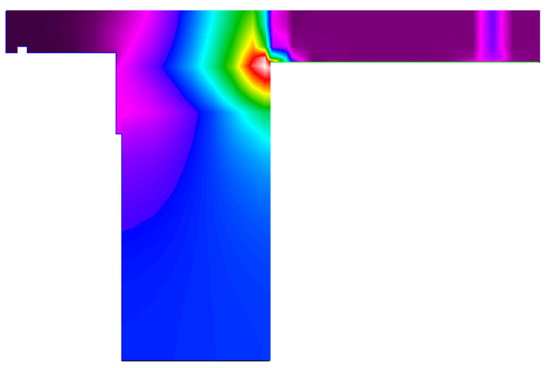
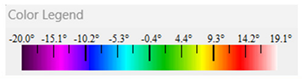
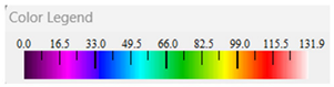
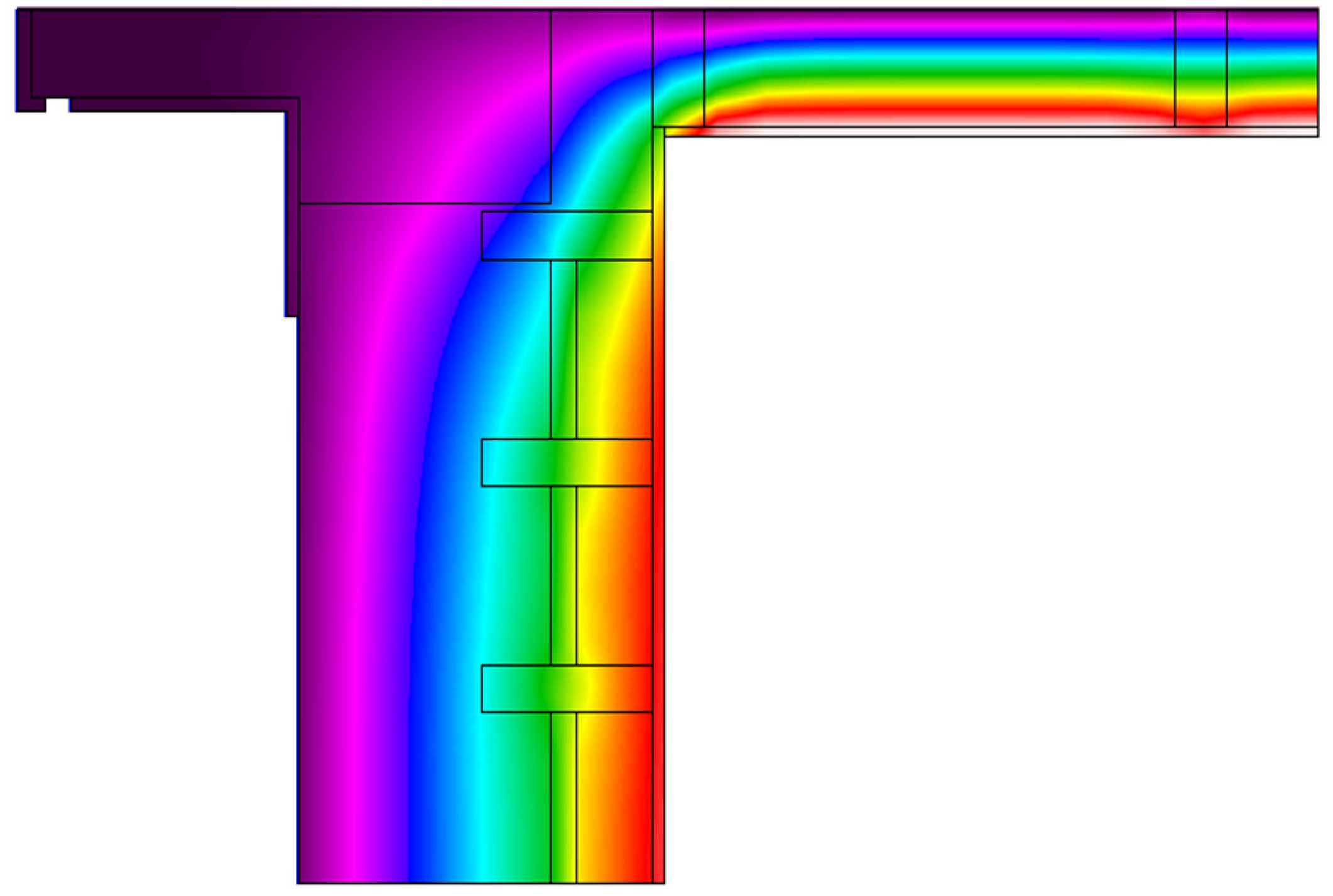
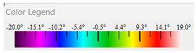
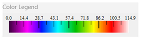
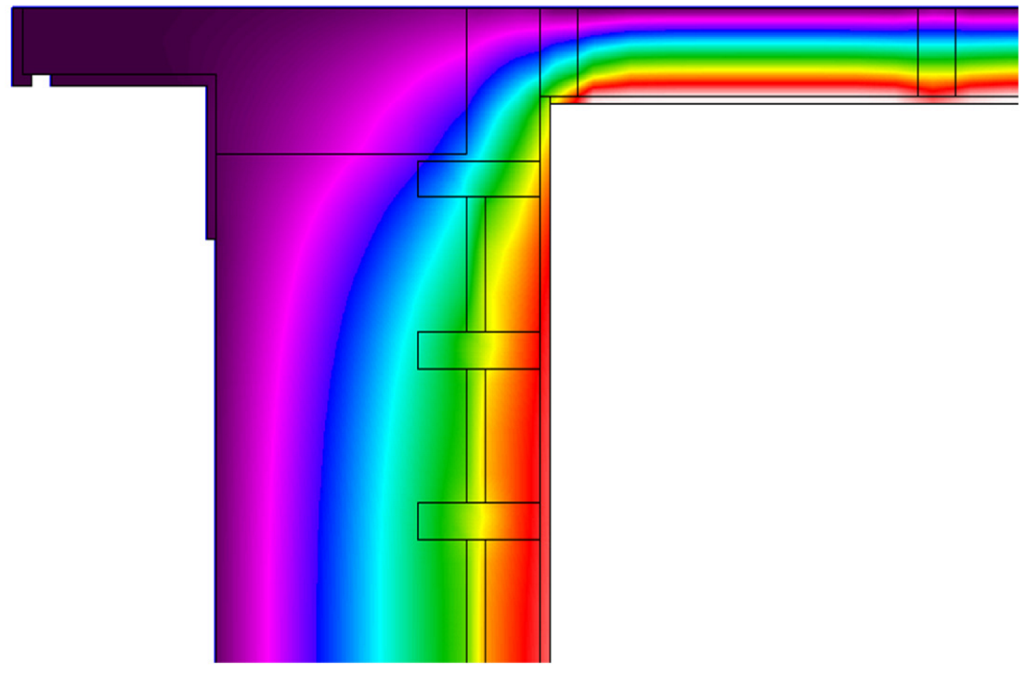
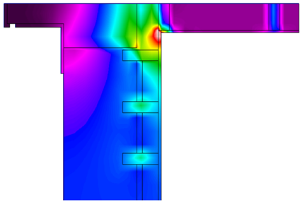
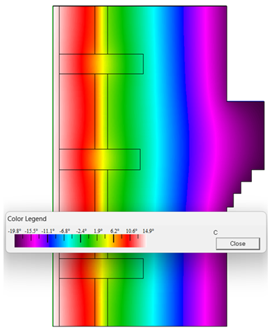
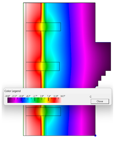
The detailed graphical and numerical results for individual variants are presented in Table 9, Table 10, Table 11, Table 12, Table 13, Table 14, Table 15, Table 16, Table 17, Table 18, Table 19, Table 20, Table 21, Table 22, Table 23 and Table 24. These tables provide temperature fields, isotherms, heat flux density distributions, and detailed temperature values at the characteristic points of the analysed building components. The detailed presentation is retained to document the thermal behaviour of each analysed configuration.
Table 9.
Tabular summary of the analysis results for Detail No. 1—Variant No. 1.
Table 10.
Tabular summary of the analysis results for Detail No. 1—Variant No. 2.
Table 11.
Tabular summary of the analysis results for Detail No. 1—Variant No. 3.
Table 12.
Tabular summary of the analysis results for Detail No. 1—Variant No. 4.
Table 13.
Tabular summary of the analysis results for Detail No. 2—Variant No. 1.
Table 14.
Tabular summary of the analysis results for Detail No. 2—Variant No. 2.
Table 15.
Tabular summary of the analysis results for Detail No. 2—Variant No. 3.
Table 16.
Tabular summary of the analysis results for Detail No. 2—Variant No. 4.
Table 17.
Tabular summary of the analysis results for Detail No. 3—Variant No. 1.
Table 18.
Tabular summary of the analysis results for Detail No. 3—Variant No. 2.
Table 19.
Tabular summary of the analysis results for Detail No. 3—Variant No. 3.
Table 20.
Tabular summary of the analysis results for Detail No. 3—Variant No. 4.
Table 21.
Tabular summary of the analysis results for Detail No. 4—Variant No. 1.
Table 22.
Tabular summary of the analysis results for Detail No. 4—Variant No. 2.
Table 23.
Tabular summary of the analysis results for Detail No. 4—Variant No. 3.
Table 24.
Tabular summary of the analysis results for Detail No. 4—Variant No. 4.
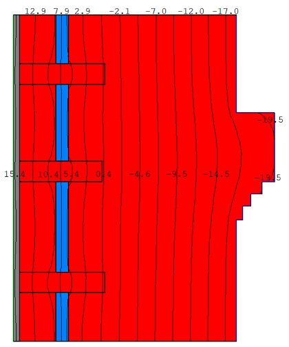
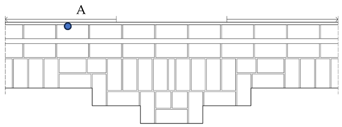
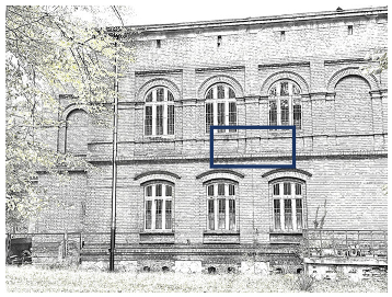
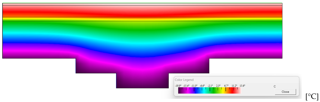
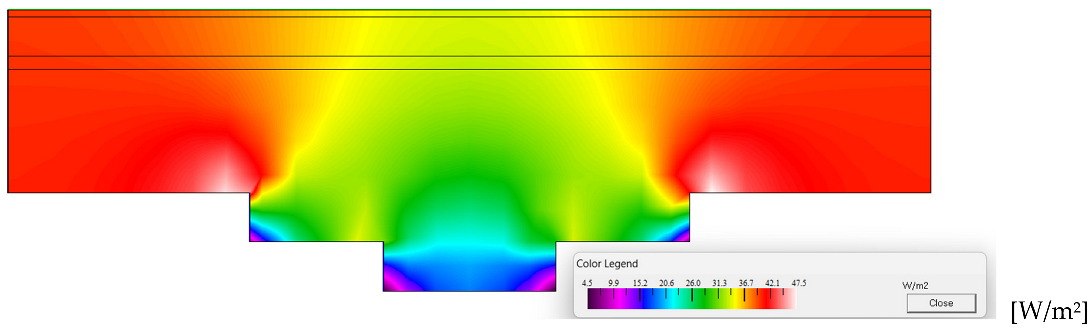
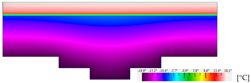
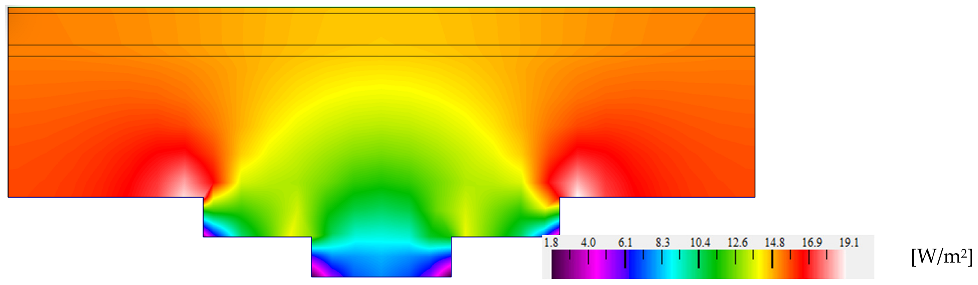
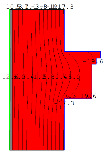
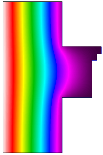
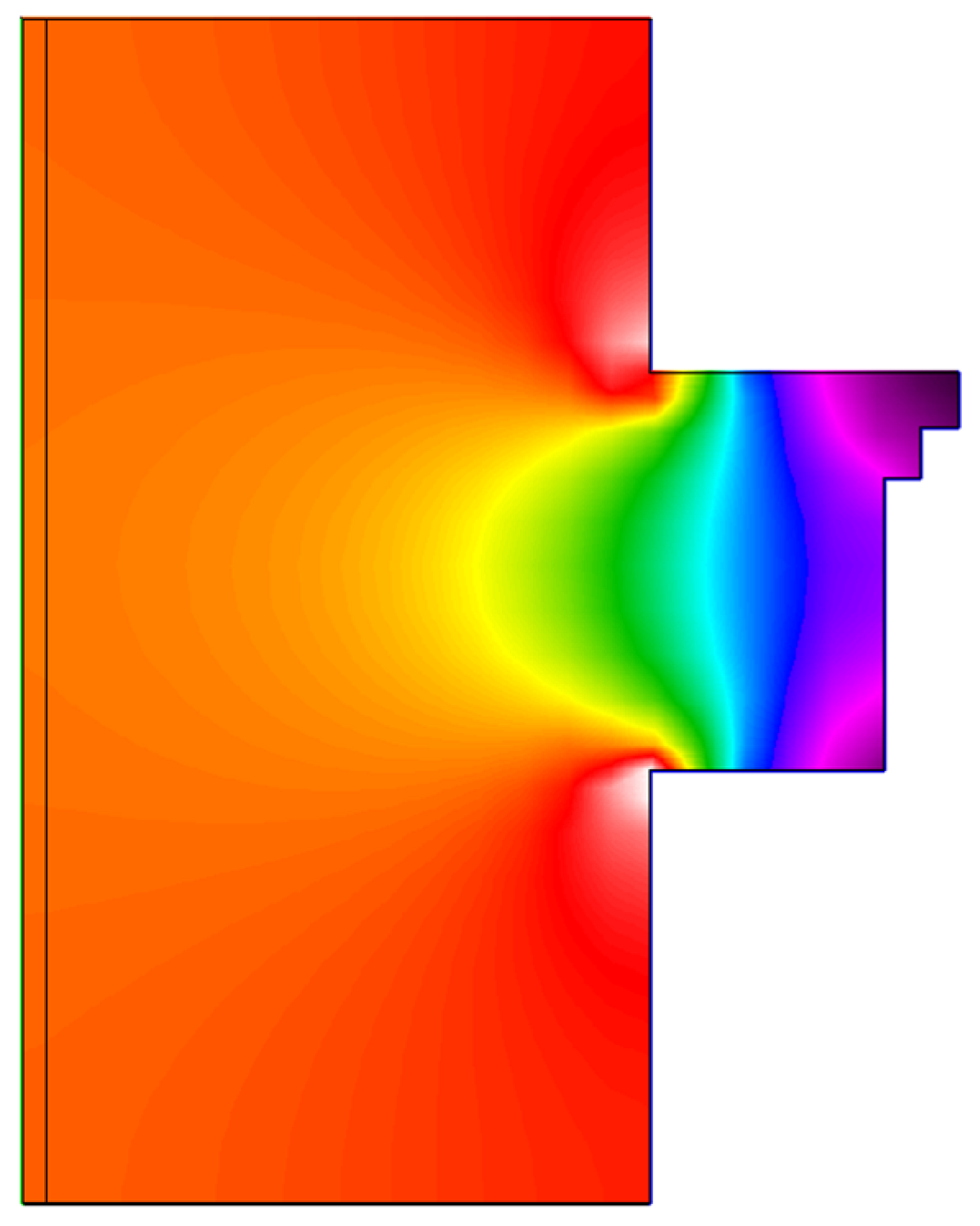
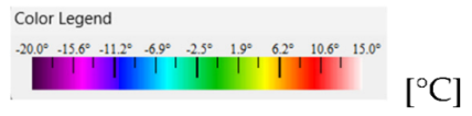
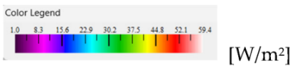
Table 9, Table 10, Table 11, Table 12, Table 13, Table 14, Table 15, Table 16, Table 17, Table 18, Table 19, Table 20, Table 21, Table 22, Table 23 and Table 24 present the complete set of graphical and calculated results for Details No. 1–4. The graphical results include temperature distributions in the form of isotherms, temperature fields, and heat flux density distributions. The calculated results include thermal transmittance, heat flow rate, thermal coupling coefficient, linear thermal transmittance, minimum surface temperature of the building component, and the internal surface temperature factor. Additionally, the obtained values of and were compared with the limiting values, i.e., and [24].
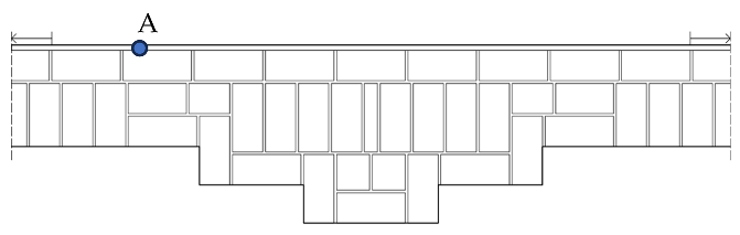
For each analysed variant, the minimum internal surface temperature, θsi,min (°C), was determined at the critical location on the internal surface of the detail. In the current set of diagrams, this location is marked as point A. The corresponding minimum internal surface temperature, θsi,min (°C), and the internal surface temperature factor, fRsi (-), are reported in the relevant results tables. These parameters were used to compare the thermal performance of the analysed detail variants.
4. Discussion
The analysis demonstrated that the thermal performance of the analysed building envelope components is influenced by both their basic structural parameters and the local geometry of architectural details. Increasing the thickness of the building envelope component resulted in a reduction in the thermal transmittance coefficient U, heat flow rate Φ, and thermal coupling coefficient L2D in all analysed cases. This relationship is consistent with the nature of heat conduction through building envelope components: increasing the heat-flow path increases the thermal resistance of the component, thereby reducing heat flow.
At the same time, the results show that changing the thickness of the building envelope component alone is insufficient to fully assess its local thermal performance. In the analysed models, significant changes in temperature distribution occurred within details whose geometry deviated from the main plane of the wall. The bending of isotherms observed around cornices, pilasters, arches, and floor elements indicates a disturbance of one-dimensional heat flow. Outside the zone affected by the detail, the isotherms became more parallel, indicating a gradual return to the heat-flow pattern characteristic of the homogeneous part of the building envelope component.
The differences between variants in which only the thickness of the building envelope component was changed and those containing an air cavity are also noteworthy. The results indicate that the configuration of the component cross-section can significantly affect the local temperature distribution, independently of the component thickness alone. The final numerical models containing an air cavity were developed in accordance with EN ISO 6946, using the thermal resistance adopted for an unventilated air layer under the specified conditions. The influence of the air cavity modelling approach is discussed in Section 4.2. This is relevant when assessing building envelope components in historic buildings, as existing walls may have heterogeneous structures and local geometric variations resulting from both construction methods and architectural details [25].
For Detail 1, which comprises a cornice, the disturbance of heat flow was visible primarily within the detail itself and around the brick bonding. The temperature distribution indicated local variations in surface temperature associated with the cornice geometry and brick arrangement. The minimum internal surface temperature, θsi,min (°C), was determined at point A, marked in the corresponding diagrams. The fRsi values were 0.818 for Variant V1, 0.855 for V2, 0.868 for V3, and 0.890 for V4. Across the analysed variants, increasing the wall thickness was associated with an increase in fRsi, indicating an improvement in the local thermal conditions assessed using the minimum internal surface temperature.
Detail 2, associated with a projecting façade element resembling a pilaster or lesene, was characterised by a more extensive zone of disturbed heat flow. The bending of the isotherms extended across the area affected by the detail geometry and diminished beyond its zone of influence. The fRsi values were 0.805 for Variant V1, 0.850 for V2, 0.873 for V3, and 0.893 for V4. These results indicate an increase in this parameter across the successive variants. The local thermal assessment was based on the minimum internal surface temperature, θsi,min, determined at point A, and the corresponding fRsi value.
In Detail 3, comprising a brick arch projecting beyond the wall face, a heat-flow disturbance mechanism similar to that observed for the cornice was identified. The isotherms bent within the arch and around the brick bonding, while heat flow gradually stabilised outside this zone. The fRsi values were 0.818 for Variant V1, 0.858 for V2, 0.870 for V3, and 0.890 for V4. An increase in this parameter was observed across the successive variants. The results show that local thermal conditions depend not only on wall thickness but also on the geometry of the analysed element.
The least favourable thermal conditions among the analysed details were observed in Detail 4, which comprises a reinforced-concrete cornice, an insulated floor, and a brick wall. In this case, heat-flow disturbances resulted from both geometric changes and the interfaces between elements made of different materials [26]. The fRsi values were 0.545 for Variant V1, 0.558 for V2, 0.623 for V3, and 0.645 for V4. Although this parameter increased across the successive variants, all values remained below the adopted criterion of 0.72. This means that none of the analysed variants of Detail 4 achieved an fRsi value meeting this criterion. The results also indicate that changes in the geometry and configuration of a detail can improve local thermal conditions without necessarily achieving the required level.
Low internal surface temperatures in thermal-bridge zones may increase the risk of surface condensation, depending on indoor air humidity conditions. Prolonged moisture accumulation may contribute to masonry deterioration and the degradation or corrosion of adjacent structural components. Maintaining sufficiently high internal surface temperatures is therefore particularly important in historic buildings [23,27]. However, the calculated surface temperatures should be interpreted in the context of the steady-state boundary conditions and material properties adopted in this study.
The values of the linear thermal transmittance coefficient ψe are also worth considering. Both positive and negative values were obtained across the analysed variants. In relation to the adopted reference configuration, positive values indicate an increase in linear heat flow, whereas negative values indicate a lower linear heat flow than that of the reference configuration. The results therefore show that the effect of the analysed details on linear heat flow depended on the geometry and configuration of each variant. A local disturbance in the temperature distribution does not necessarily correspond to a large additional linear heat flow. Consequently, an assessment based solely on ψe may not fully reflect the local thermal conditions.
A similar conclusion can be drawn from the thermal transmittance coefficient U. Despite the reduction in U with increasing wall thickness, none of the analysed variants achieved a value below 0.20 W/(m2·K), which was adopted in this study as a reference value for contemporary requirements for external walls. However, comparing the calculated values with the requirements for contemporary building envelope components should not be interpreted as a direct assessment of the feasibility of retrofitting the historic building as a whole. The results primarily demonstrate that increasing the thickness of an existing building envelope component without adding an insulation layer is insufficient to achieve the contemporary level of thermal insulation.
The analyses indicate that the influence of detail geometry should be assessed primarily in terms of the local temperature field, the minimum internal surface temperature θsi,min, and the corresponding fRsi value, rather than solely through the global parameters of the building envelope component. This is particularly evident in Detail 4, which yielded the lowest fRsi values, with all variants remaining below the adopted criterion of 0.72. The ψe values, in turn, indicate that local geometric effects may be apparent in the temperature distribution even when the linear thermal transmittance coefficient does not indicate additional heat flow relative to the reference configuration.
From the perspective of energy retrofitting historic buildings, these findings indicate that the thermal assessment of building envelope components containing architectural details should not be limited to a one-dimensional analysis of the main wall section. The actual geometry of preserved façade elements may affect local thermal conditions and should therefore be considered when evaluating proposed retrofit solutions. The significance of a detail depends on its geometry, position, and relationship with the other components of the building envelope. Two-dimensional modelling therefore enables a more detailed identification of local thermal phenomena than an analysis restricted to a homogeneous wall section.
4.1. Scope and Limitations of the Study
The scope of the present study should be considered when interpreting the obtained results. First, the analysis was conducted for a single historic hospital complex. Although the four analysed architectural details were selected as characteristic of the investigated complex, the results should not be regarded as universally representative of historic masonry buildings with different construction traditions, materials, geometries, or climatic conditions.
Second, the analyses were performed using two-dimensional steady-state heat-transfer models. This approach was appropriate for the comparative assessment of the sixteen variants under identical boundary conditions and enabled the influence of geometry and construction on local thermal conditions to be assessed consistently. However, steady-state modelling does not account for transient changes in outdoor and indoor temperatures, solar gains, thermal storage in massive masonry, or time-dependent moisture transport.
The numerical procedure was assessed using the EN ISO 10211 benchmark test and a mesh-refinement assessment for a selected configuration. The results showed that the heat flow rate and thermal transmittance remained stable across the tested mesh configurations. The minimum internal surface temperature and fRsi also remained unchanged at the reported precision across the three finer configurations. However, the assessment was limited to the selected configuration and the tested numerical settings; it therefore does not establish mesh independence for all sixteen analysed variants. Direct measurements performed on the investigated building would provide an additional level of validation under real operating conditions.
Another limitation concerns the thermophysical properties adopted for the historic materials. These properties were based on technical literature and reference data and corresponded to the assumed medium-moisture condition. They were applied consistently throughout the numerical analysis but were not determined experimentally for the individual materials and construction layers of the investigated building. Direct sampling was not undertaken due to the conservation constraints associated with the protected historic building. The assumed moisture condition should therefore be understood as a reference calculation condition rather than a verified representation of the in situ moisture state of the masonry. Actual material properties may vary depending on composition, density, moisture content, ageing, and technical condition. Since no formal sensitivity or uncertainty analysis of these material properties was performed, the influence of these variations on the calculated results could not be quantified. Consequently, the results should primarily be interpreted as a comparative assessment of the analysed configurations under the adopted material properties, boundary conditions, and air cavity modelling assumptions.
Future research should therefore include in situ measurements of surface temperatures and heat fluxes to further validate the numerical results. Transient hygrothermal simulations should also be performed to investigate the influence of moisture transport and changing boundary conditions on the thermal behaviour of historic masonry. Finally, three-dimensional modelling should be considered for architectural details with significant out-of-plane geometry, where a two-dimensional representation may not fully capture the actual heat-flow pattern. Dynamic hygrothermal effects, including transient moisture transport and seasonal moisture accumulation, were not considered and should be addressed in future research.
The numerical models assume continuous contact between the material layers and do not account for local defects such as gaps, imperfect mortar contact, or plaster detachment, which may locally affect heat and moisture transfer [27]. The present study does not include numerical variants with additional thermal insulation or other retrofit measures; therefore, the results should not be interpreted as a direct assessment of the effectiveness of specific energy-retrofit solutions. Future studies should assess compatible retrofit solutions using coupled thermal and hygrothermal analyses while preserving the actual geometry of the historic architectural details.
4.2. Influence of Air Cavity Modelling on the Calculated Thermal Performance
To evaluate the influence of the air cavity modelling approach on the calculated thermal performance, two models of Detail 1, Variant 3, were compared. In the baseline model (V1_3), the 4 cm air cavity was modelled in accordance with EN ISO 6946, using a thermal resistance of 0.18 m2·K/W. In the comparison model, the 4 cm air cavity was represented as stagnant air, with an assumed thermal conductivity of 0.025 W/(m·K).
Table 25 presents the calculated thermal transmittance, heat flow rate and minimum surface temperature for both modelling approaches. For the EN ISO 6946-based model, the thermal transmittance was 1.06 W/(m2·K), and the heat flow rate was 41.30 W. The corresponding values for the stagnant-air model were 0.81 W/(m2·K) and 31.50 W, respectively. The minimum surface temperature was 14.7 °C for the EN ISO 6946-based model and 15.6 °C for the stagnant-air model.
Table 25.
Comparison of the calculated thermal parameters for two air cavity modelling approaches.
The comparison shows that the choice of air cavity modelling approach affects the calculated thermal parameters. Compared with the stagnant-air model, the EN ISO 6946-based model yielded a thermal transmittance higher by 0.25 W/(m2·K) and a heat flow rate higher by 9.80 W. Its minimum surface temperature was 0.9 °C lower.
The comparison in Table 25 is limited to Detail 1, Variant 3, and is intended to illustrate the sensitivity of the calculated thermal parameters to the representation of the air cavity. It does not, by itself, quantify the effect of the alternative representation across all sixteen variants. The results reported for the final set of variants are based on the EN ISO 6946-based representation adopted for the air cavity. Therefore, the interpretation of the sixteen variants should be understood as conditional on this modelling assumption. The comparison also indicates that results obtained using the alternative stagnant-air representation should not be directly combined with, or treated as interchangeable with, the results of the final models.
Despite yielding higher values of thermal transmittance and heat flow rate in the analysed case, the EN ISO 6946-based approach was adopted for the final models because it provides a standardised basis for representing the thermal resistance of an unventilated air layer under specified conditions. The choice was therefore based on methodological consistency with the adopted standard rather than on obtaining more favourable thermal performance indicators.
5. Conclusions
The numerical analysis made it possible to determine the influence of the geometry and construction of selected architectural details on the local thermal conditions of historic masonry building envelope components. Based on the obtained results, the following conclusions were formulated:
The geometry of architectural details affects the local thermal conditions of historic building envelope components, and its significance depends on the shape, thickness, and construction of the detail.
Increasing the thickness of the building envelope component improves its thermal insulation, but does not, in itself, ensure compliance with contemporary requirements for the thermal transmittance coefficient (U). None of the analysed variants achieved a (U)-value below 0.20 W/(m2·K).
The adopted representation of the unventilated air cavity affected the calculated thermal parameters. The comparison for Detail 1, Variant 3, showed differences in thermal transmittance, heat flow rate, and minimum internal surface temperature between the EN ISO 6946-based model and the alternative stagnant-air model. As this comparison was performed for one variant, the magnitude of these differences should not be generalised to all analysed details. The results for the sixteen variants should therefore be interpreted in the context of the air-cavity representation adopted in the final models.
The thermal assessment of historic building envelope components requires individual consideration of their actual geometry and construction. Particular attention should be paid to areas with changes in geometry and material interfaces. The results for Detail 4 demonstrate that its thermal performance remained critical: all analysed variants had fRsi values below the adopted criterion of 0.72.
Author Contributions
Conceptualization, B.O.-K., A.S.-G. and A.S.; methodology, B.O.-K., A.S.-G. and A.S.; software, A.S.; validation, B.O.-K.; formal analysis, B.O.-K., A.S.; investigation, B.O.-K., A.S.-G. and A.S.; resources, B.O.-K., A.S.-G.; data curation, B.O.-K., A.S.-G. and A.S.; writing—original draft preparation, B.O.-K., A.S.-G. and A.S.; writing—review and editing, B.O.-K.; visualization, A.S.; supervision, A.S.-G.; project administration, B.O.-K. All authors have read and agreed to the published version of the manuscript.
Funding
This research received no external funding.
Data Availability Statement
Data is contained within the article.
Conflicts of Interest
Adrianna Szlęk is employed by Pekabex Bet S.A. The other author declares no conflict of interest.
References
- Martínez-Molina, A.; Tort-Ausina, I.; Cho, S.; Vivancos, J.-L. Energy Efficiency and Thermal Comfort in Historic Buildings: A Review. Renew. Sustain. Energy Rev. 2016, 61, 70–85. [Google Scholar] [CrossRef] [Scilit]
- Webb, A.L. Energy Retrofits in Historic and Traditional Buildings: A Review of Problems and Methods. Renew. Sustain. Energy Rev. 2017, 77, 748–759. [Google Scholar] [CrossRef] [Scilit]
- Lidelöw, S.; Örn, T.; Luciani, A.; Rizzo, A. Energy-Efficiency Measures for Heritage Buildings: A Literature Review. Sustain. Cities Soc. 2019, 45, 231–242. [Google Scholar] [CrossRef] [Scilit]
- Nair, G.; Verde, L.; Olofsson, T. A Review on Technical Challenges and Possibilities on Energy Efficient Retrofit Measures in Heritage Buildings. Energies 2022, 15, 7472. [Google Scholar] [CrossRef] [Scilit]
- PN-EN 16883:2017-07; Konserwacja Dziedzictwa Kulturowego—Wytyczne Dotyczące Poprawy Charakterystyki Energetycznej Budynków Zabytkowych. Polski Komitet Normalizacyjny (PKN): Warszawa, Poland, 2017.
- Murgul, V.; Pukhkal, V. Saving the Architectural Appearance of the Historical Buildings Due to Heat Insulation of Their External Walls. Procedia Eng. 2015, 117, 891–899. [Google Scholar] [CrossRef] [Scilit]
- Orlik-Kożdoń, B. Interior Insulation of Masonry Walls—Selected Problems in the Design. Energies 2019, 12, 3895. [Google Scholar] [CrossRef] [Scilit]
- Walker, R.; Pavía, S. Thermal Performance of a Selection of Insulation Materials Suitable for Historic Buildings. Build. Environ. 2015, 94, 155–165. [Google Scholar] [CrossRef] [Scilit]
- Hansen, T.K.; Bjarløv, S.P.; Peuhkuri, R.H.; Harrestrup, M. Long Term In Situ Measurements of Hygrothermal Conditions at Critical Points in Four Cases of Internally Insulated Historic Solid Masonry Walls. Energy Build. 2018, 172, 235–248. [Google Scholar] [CrossRef] [Scilit]
- Biseniece, E.; Žogla, G.; Kamenders, A.; Purviņš, R.; Kašs, K.; Vanaga, R.; Blumberga, A. Thermal Performance of Internally Insulated Historic Brick Building in Cold Climate: A Long Term Case Study. Energy Build. 2017, 152, 577–586. [Google Scholar] [CrossRef] [Scilit]
- Andreotti, M.; Calzolari, M.; Davoli, P.; Dias Pereira, L. Hygrothermal Performance of an Internally Insulated Masonry Wall: Experimentations without a Vapour Barrier in a Historic Italian Palazzo. Energy Build. 2022, 260, 111896. [Google Scholar] [CrossRef] [Scilit]
- Odgaard, T.; Bjarløv, S.P.; Rode, C. Influence of Hydrophobation and Deliberate Thermal Bridge on Hygrothermal Conditions of Internally Insulated Historic Solid Masonry Walls with Built-in Wood. Energy Build. 2018, 173, 530–546. [Google Scholar] [CrossRef] [Scilit]
- Curto, D.; Franzitta, V.; Guercio, A.; Martorana, P. FEM Analysis: A Review of the Most Common Thermal Bridges and Their Mitigation. Energies 2022, 15, 2318. [Google Scholar] [CrossRef] [Scilit]
- Ahnert, R.; Krause, K.H. Typische Baukonstruktionen von 1860 bis 1960 zur Beurteilung der Vorhandenen Bausubstanz. Band 1; Bauverlag: Wiesbaden/Berlin, Germany.
- Mączeński, Z. Elementy i Detale Architektoniczne w Rozwoju Historycznym; Budownictwo i Architektura: Warszawa, Poland, 1956. [Google Scholar]
- Kliniczny Szpital Psychiatryczny SPZOZ w Rybniku. Historia Szpitala. Available online: https://psychiatria.com/o-nas/historia/ (accessed on 11 September 2026).
- Archiwum Państwowe w Katowicach, Oddział w Raciborzu. Śląski Zakład Psychiatryczny w Rybniku, Zespół nr 18/149/0. Available online: https://www.szukajwarchiwach.gov.pl/en/zespol/-/zespol/132150 (accessed on 11 September 2026).
- Kruszewski, T. Prowincjonalna Opieka nad Chorymi Psychicznie na Śląsku w XIX i Pierwszej Połowie XX Wieku; Wydawnictwo Uniwersytetu Wrocławskiego: Wrocław, Poland, 2016; ISBN 978-83-61370-87-1. [Google Scholar]
- Lawrence Berkeley National Laboratory. THERM Software Downloads. Building Technologies Office, Windows & Daylighting. Available online: https://windows.lbl.gov/therm-software-downloads (accessed on 10 September 2026).
- ISO 10211:2017; Thermal Bridges in Building Construction—Heat Flows and Surface Temperatures—Detailed Calculations. International Organization for Standardization: Geneva, Switzerland, 2017.
- PN-EN 12831:2006; Instalacje Ogrzewcze w Budynkach—Metoda Obliczania Projektowego Obciążenia Cieplnego. Polski Komitet Normalizacyjny: Warszawa, Poland, 2006.
- ISO 6946:2017; Building Components and Building Elements—Thermal Resistance and Thermal Transmittance—Calculation Methods. International Organization for Standardization: Geneva, Switzerland, 2017.
- ISO 13788:2012; Hygrothermal Performance of Building Components and Building Elements—Internal Surface Temperature to Avoid Critical Surface Humidity and Interstitial Condensation—Calculation Methods. International Organization for Standardization: Geneva, Switzerland, 2012.
- Rozporządzenie Ministra Infrastruktury z dnia 12 kwietnia 2002 r. w sprawie warunków technicznych, jakim powinny odpowiadać budynki i ich usytuowanie, tekst jednolity ogłoszony w Obwieszczeniu Ministra Rozwoju i Technologii z dnia 15 kwietnia 2022 r., Dz.U. 2022 poz. 1225. Available online: https://dziennikustaw.gov.pl/D2022000122501.pdf (accessed on 11 September 2026).
- Gutland, M.; Bucking, S.; Santana Quintero, M. Hygrothermal Modelling of Historic Rubble Masonry Walls: Accounting for Geometric and Compositional Variability. J. Build. Eng. 2022, 48, 103929. [Google Scholar] [CrossRef] [Scilit]
- Evola, G.; Gagliano, A. Experimental and Numerical Assessment of the Thermal Bridging Effect in a Reinforced Concrete Corner Pillar. Buildings 2024, 14, 378. [Google Scholar] [CrossRef] [Scilit]
- Semko, O.; Vynnykov, Y.; Filonenko, O.; Yurin, O.; Ilchenko, T.; Hranko, O.; Semko, V.; Salles, A.; Mateus, R.; Bragança, L.; et al. To the Issue of Assessment of the Technical Condition of Underground Structures of Buildings. Sustainability 2025, 17, 2264. [Google Scholar] [CrossRef] [Scilit]










Disclaimer/Publisher’s Note: The statements, opinions and data contained in all publications are solely those of the individual author(s) and contributor(s) and not of MDPI and/or the editor(s). MDPI and/or the editor(s) disclaim responsibility for any injury to people or property resulting from any ideas, methods, instructions or products referred to in the content. |
© 2026 by the authors. Licensee MDPI, Basel, Switzerland. This article is an open access article distributed under the terms and conditions of the Creative Commons Attribution (CC BY) license.