


Abstract
This study presents a comparative experimental and numerical investigation of two solar air heater (SAH) configurations: a flat-panel absorber (F-SAH) and a longitudinal-baffle absorber (LB-SAH). Experiments were conducted under real outdoor conditions at mass flow rates of 0.00410, 0.00513, and 0.00616 kg s−1, and a three-dimensional CFD model was developed in ANSYS Fluent using the SST k–ω turbulence closure. The numerical results showed excellent agreement with experimental data, with a mean deviation not exceeding 4.5%. The LB-SAH consistently outperformed the F-SAH across all operating conditions. For experimental results, the maximum outlet air temperature reached 97 °C for the LB-SAH compared to 79 °C for the F-SAH at a mass flow rate of 0.00410 kg s−1. The thermal efficiency of the LB-SAH ranged from 47.76% to 64.51% as the mass flow rate increased from 0.00410 to 0.00616, compared to 30.77–47.76% for the F-SAH. The LB-SAH achieved Nusselt numbers up to 110.18% higher than those for the F-SAH, with heat transfer coefficients of up to 16.61 W m−2 K−1. The thermohydraulic performance parameter (THPP) reached 1.49 for the LB-SAH configuration at m = 0.00616 kg s−1, confirming significant net energy gains compared to the results for the F-SAH configuration. These findings establish the LB-SAH as the superior configuration in terms of thermal performance, while highlighting the F-SAH as the preferred choice when minimizing hydraulic resistance is a priority. While the LB-SAH significantly enhances heat transfer performance, this improvement is accompanied by an increased pressure drop and higher fan power requirements.
1. Introduction
The continuous growth in global energy demand, coupled with escalating environmental concerns and greenhouse gas emissions, has intensified the need for sustainable and renewable energy technologies. Meeting the world’s growing demand for heating, drying, and electricity in a sustainable manner requires a decisive transition toward renewable energy sources. Among renewable resources, solar energy represents one of the most abundant and environmentally benign sources [1,2]. Egypt, with its high solar irradiance and extended sunshine duration, presents ideal conditions for solar energy applications [3,4]. In particular, low- and medium-temperature solar thermal systems play a significant role in applications such as space heating, agricultural drying, ventilation preheating, and industrial process heating. Due to their simple construction, low operating costs, and minimal maintenance requirements, solar air heaters (SAHs) are widely recognized as practical devices for utilizing direct solar energy [5]. Their straightforward design, low maintenance requirements, and compatibility with decentralized installations make them particularly attractive for rural and developing regions, where access to conventional energy infrastructure may be limited.
A conventional SAH consists of an absorber plate, a transparent glazing cover, an insulated back panel, and inlet/outlet ports. The absorber plate intercepts incoming solar radiation and transfers the accumulated heat to a flowing air stream [6]. Despite their structural simplicity and low fabrication cost, conventional flat-plate SAHs suffer from poor convective heat transfer between the absorber surface and the air stream, leading to significant thermal losses and limited efficiency. This fundamental limitation has driven extensive research efforts to enhance the thermal performance of SAHs through geometric modifications, surface treatments, and flow-path restructuring [7,8]. A widely adopted strategy for improving SAH performance is the introduction of roughness elements—such as ribs, grooves, fins, and baffles—on the absorber surface. These features disrupt the laminar sublayer of the boundary layer, promote flow separation and reattachment, and induce secondary vortical structures that intensify convective heat transfer [9,10].
Jin et al. [11] numerically demonstrated that multiple V-shaped ribs yield a maximum thermal-hydraulic performance parameter (THPP) of 2.35, while Salarpour & Azadani [10] found that, among six roughness geometries evaluated, rectangular baffles achieve the highest THPP of 2.28 at Re = 25,000. Azadani & Gharouni [12] optimized cylindrical roughness elements in a square-duct SAH, obtaining a maximum THPP of 1.20. Kumar & Layek [13] reported improvements of 2.12, 1.99, and 2.03 in thermal, effective, and energy efficiencies, respectively, for a fin-type roughness absorber compared to the results for a smooth plate. Flow path modification through the strategic placement of baffles and deflectors constitutes another effective design approach. By guiding the air along a controlled trajectory, baffles extend the heat-extraction time and increase the effective heat-transfer surface area [14,15]. Wang [16] demonstrated that semi-circular baffles creating a helical airflow pattern produce a 27 K increase in outlet temperature and a 20% boost in thermal efficiency over the results for conventional collectors.
Computational fluid dynamics (CFD) has emerged as an indispensable tool for designing and optimizing solar air heaters, enabling researchers to investigate complex three-dimensional flow structures, temperature gradients, and pressure fields that are difficult or impossible to resolve through experimental measurements alone. Researchers numerically solve the governing continuity, momentum, and energy equations, along with turbulence closure models, over discretized computational domains, providing high-resolution insight into local heat-transfer mechanisms [17,18,19]. Numerous CFD studies have demonstrated the capability of numerical simulation to accurately reproduce experimental measurements of outlet temperature, Nusselt number, and pressure drop in a wide range of SAH configurations. Mund et al. [20] presented a comprehensive review of CFD-based analyses of SAHs, highlighting the versatility of ANSYS Fluent in resolving turbulent heat transfer characteristics across a broad range of absorber geometries, with reported numerical uncertainties typically below 10%. Prasad et al. [21] used three-dimensional CFD modelling to investigate a SAH with offset transverse ribs, achieving Nusselt number enhancements of up to 3.36 times the results for a smooth duct, while maintaining acceptable friction factor increases.
Wang et al. [22] performed CFD simulations of a SAH with sinusoidal baffles and demonstrated that sinusoidal profiles yield superior heat collection efficiency (64.49%) and lower pressure losses compared to the results for folded and semi-circular baffle configurations, with an optimal wavelength of 200 mm. El-Sebaey et al. [23] developed a three-dimensional unsteady CFD model using the RNG k-ε turbulence model to evaluate two flat-plate SAH configurations under Egyptian climatic conditions, achieving deviations between simulated and measured outlet temperatures of 7.0–7.8%, consistent with the accepted accuracy range for SAH CFD models. Chang et al. [24] developed two CFD models for SAHs to determine the optimal baffle type (longitudinal and transverse baffles) and the number of baffles. Their results showed that transverse baffles improve SAH efficiency by 2.34–6.97% compared to the results for longitudinal baffles. Afshari et al. [25] investigated different designs and placements of turbulators within a cost-effective tube-type SAH to enhance thermal performance. Both experimental measurements and CFD analyses were conducted to evaluate the performance of the solar heating system. The results identified full fine turbulators as the optimal configuration for tubular SAHs, achieving a maximum thermal efficiency of 72.41%. Amara et al. [26] experimentally and numerically investigated spiral-shaped baffle heights, reporting a peak exit temperature of 77.7 °C at an inlet velocity of 5 m s−1 and a 13% performance improvement for a baffle height of 110 mm.
Although SAH enhancement has been widely studied using transverse ribs, V-shaped elements, and spiral or helical paths, the specific configuration of straight longitudinal baffles standing vertically on the absorber plate surface, forming a series of parallel enclosed channels along the flow direction, represents a distinct and underexplored design paradigm. Unlike transverse baffles oriented perpendicular to flow, these vertical longitudinal dividers guide the air along extended parallel passages in direct contact with the heated absorber surface, significantly increasing the air–absorber residence time and the contact area. This geometry differs fundamentally from that comprising surface-mounted ribs and fins, which create localized turbulence at discrete points, and from spiral or helical configurations, which restructure the entire collector flow trajectory into a single winding path. The straight longitudinal baffle design therefore provides a structurally simple and manufacturable means of extending heat extraction time while maintaining moderate pressure losses. Despite these geometric distinctions, no published study has directly compared F-SAHs and LB-SAHs, particularly in an air channel located beneath the absorber surface and under identical climatic and operating conditions, multiple mass flow rates, and a combined experimental–CFD framework—a gap addressed by the present study.
Therefore, this study aims to design, fabricate, and experimentally evaluate two SAH prototypes, F-SAH and LB-SAH, under real environmental conditions. In parallel, a steady-state three-dimensional CFD model is developed for both configurations using the SST k–ω turbulence model in ANSYS Fluent, and the numerical results are validated against experimental measurements. Furthermore, a comprehensive performance comparison is conducted in terms of outlet air temperature, thermal efficiency, convective heat transfer coefficient (h), Nusselt number (Nu), and THPP at three mass flow rates (0.0041, 0.00513, and 0.00616 kg s−1).
2. Materials and Methods
2.1. Experimental Setup and Data Collection
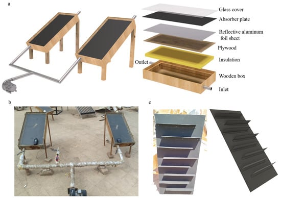
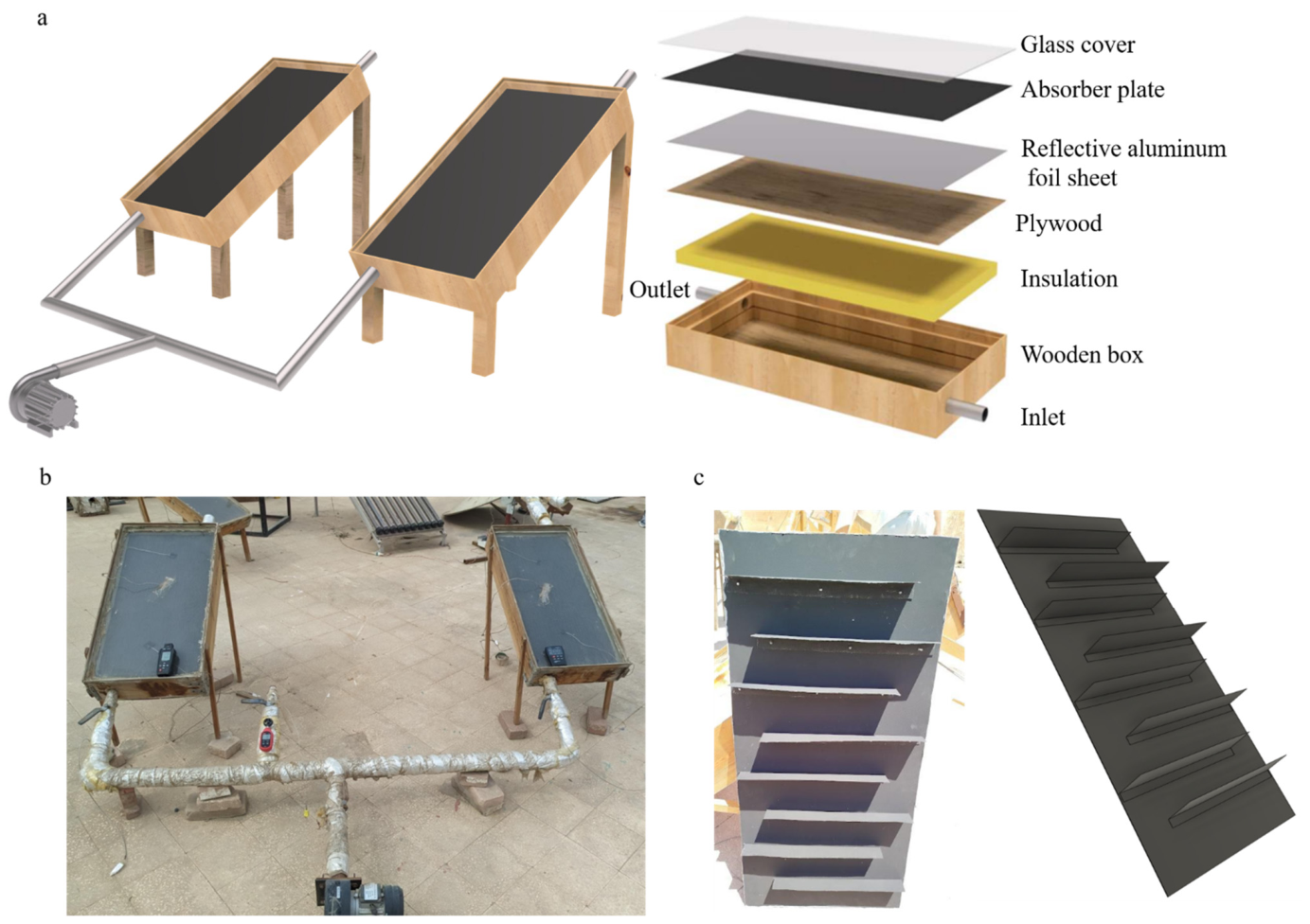
Outdoor experiments were conducted on two SAH configurations mounted on a south-facing test rig in the Faculty of Agriculture, Ain Shams University, Egypt, during July 2025. The first is a flat-plate SAH (F-SAH), and the second is a longitudinal-baffled SAH (LB-SAH). The two SAHs were intentionally constructed with the same overall dimensions, housing, glazing, insulation, inlet–outlet geometry, and airflow arrangement so that the only controlled variable between the systems was the absorber plate shape (Figure 1). Each SAH comprised a rectangular collector box with internal dimensions of 1000 mm × 500 mm × 145 mm, fabricated as a wooden structure and internally coated with black paint to reduce internal reflection and promote absorption of incident and re-radiated energy. Air entered and exited through steel inlet and outlet sections, 33 mm in diameter, providing a consistent flow at the entrance and exit for both collectors. Both collectors share the same external envelope: a rectangular air channel with dimensions of 1000 mm × 500 mm × 50 mm. A single glass cover of 1000 mm × 500 mm and 4 mm thickness was used for both units; the glass had a reported transmissivity of 0.9 and emissivity of 0.85, allowing high solar transmittance while limiting radiative heat exchange with the environment. The absorber plate is a 1 mm thick aluminum sheet coated with black paint (absorptivity α ≈ 0.90, emissivity ε ≈ 0.90). To minimize conductive losses from the bottom and sides, both collectors were insulated using glass wool with a thickness of 50 mm.
Figure 1.
(a) Sketch drawing; (b) photograph of experiment setup; (c) sketch drawing and photograph of the longitudinal-baffle absorber.
In the F-SAH system, the absorber was a conventional flat aluminum plate, creating a relatively uniform flow path beneath the plate. As shown in Figure 1c, the LB-SAH incorporates eight longitudinal alternating baffles (400 mm length × 50 mm height × 0.1 mm thickness). These baffles act as flow dispersers, enhancing vortex motion, generating secondary vortices, increasing turbulence intensity, and repeatedly disrupting the thermal boundary layer formed within the airflow channel beneath the absorber. This geometry enhances the residence time of the flow and the thermal reaction without altering the overall dimensions of the collector. In both collectors, the air mass flow was directed beneath the absorber plate, making the absorber’s heated underside the primary heat-transfer surface for convection. Under this airflow configuration, beneath the absorber, air enters through the inlet section, passes through the underside channel where it absorbs heat by forced convection, and then exits through the outlet section.
2.2. Experimental Procedure
Both SAHs were mounted on a wooden frame at a fixed inclination of 30°, corresponding to the optimal tilt angle for Cairo, Egypt. The collectors were oriented due south to maximize incident solar radiation throughout the testing period. Forced airflow was provided using a centrifugal fan rated at 2800 rpm, 180 W, and 220 V, enabling controlled operation across the tested mass flow rate range. Two control valves (Figure 1b) were incorporated to regulate and stabilize the mass flow rate. During all tests, ambient air was delivered to the collectors at three mass flow rates: 0.0041, 0.00513, and 0.00616 kg s−1.
During the test, solar radiation intensity, inlet air temperature, outlet air temperature, absorber plate temperature, airflow velocity, and ambient temperature were measured continuously, allowing for the direct computation of useful heat gain and thermal efficiency under real operating conditions. The specifications and measurement characteristics of the instruments employed are summarized in Table 1. Measurements were recorded at one-hour intervals throughout the testing period. The experiments were conducted in the summer season in July 2025.
Table 1.
Specifications and measurement characteristics of the instruments used in the experimental study.
2.3. Numerical Modeling
2.3.1. Governing Equations, Turbulence Closure, and Computational Domain
All simulations solve the incompressible Reynolds-Averaged Navier–Stokes (RANS) equations for conservation of mass, momentum, and energy in the air domain [17]:
where ρ is air density, u is the velocity vector, p is static pressure, μ is dynamic viscosity, gravitational force acting on the fluid, total energy per unit mass, T is temperature, and kf is thermal conductivity. Turbulence closure is provided by the k–ω Shear Stress Transport (SST) model, which combines the robustness of the k–ε formulation in the free-stream with the accuracy of the k–ω model in the near-wall region. The model solves transport equations for turbulent kinetic energy k and specific dissipation rate ω [17]:
where Gk and Gω represent production of k and ω, Yk and Yω represent their dissipation, and Dω is the cross-diffusion term. Standard Wall Functions (SWF) are applied at all no-slip boundaries, employing the logarithmic law-of-the-wall to bridge the viscous sublayer without requiring mesh refinement to the wall.
For the F-SAH, the computational domain consists of two zones: the air channel fluid domain and the solid aluminum absorber plate, treated using a conjugate heat transfer (CHT) approach. The CHT framework captures conduction across the 1 mm absorber plate and coupled convective exchange at the fluid–solid interface, without requiring an explicit heat-flux split between conduction and convection. For the LB-SAH, the computational domain is a single fluid zone in which the eight baffles are represented as zero-thickness internal wall surfaces with adiabatic boundary conditions. This thin-wall approach avoids the severe mesh distortion that would result from discretizing 0.1 mm baffle features within a domain meshed at 5 mm and is consistent with the negligible conductive resistance of the thin aluminum baffles. All simulations were performed using ANSYS Fluent 2024 R2.
The inlet boundary was defined based on measured airflow conditions corresponding to the experimental mass flow rates. The outlet boundary was specified using a pressure-based condition at atmospheric pressure. Thermal boundary conditions were applied based on the measured solar irradiance and absorber thermal properties: the net heat flux delivered to the absorber surface was computed as q = G × τglass × αabs, consistent with the material properties of the experimental prototype. Non-slip conditions were imposed on all solid walls. The lateral and bottom walls of the collector were treated as adiabatic, reflecting the thermal insulation provided by the wooden insulation layer used in the experimental setup. Radiative heat transfer within the air channel was accounted for using the Discrete Ordinates (DO) radiation model to capture surface-to-surface radiation exchange between the absorber plate and the surrounding walls. Convective heat loss from the top surface of the collector to the outdoor environment was represented through a convective heat transfer coefficient estimated from the measured wind speed data, following the approach of Amara et al. [17]. It is acknowledged that outdoor environmental variability, including fluctuating wind speed, solar elevation angle, and humidity, introduces experimental uncertainty that cannot be fully replicated under steady-state boundary conditions and represents the primary source of the localized deviations observed at early operating hours, as discussed in Section 4.2.
2.3.2. Mesh Generation and Independence Study
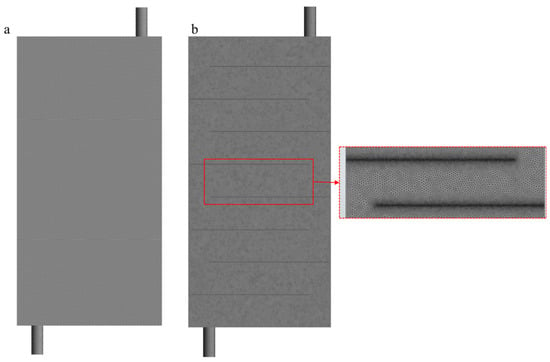
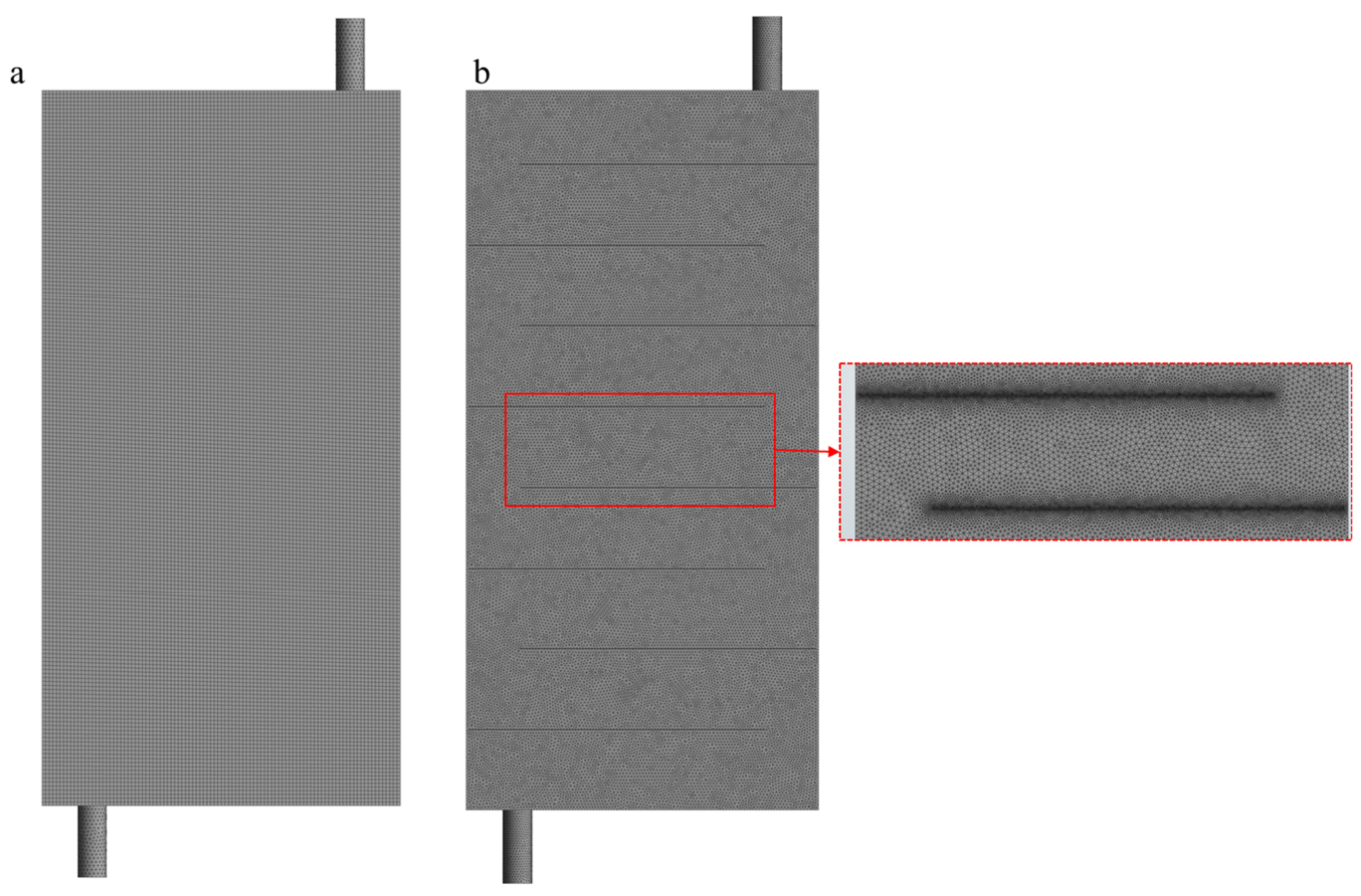
The F-SAH mesh was generated using ANSYS Fluent 2024 R2 Mechanical with CFD Physics Preference. An unstructured tetrahedral mesh was chosen to accommodate the cylindrical inlet/outlet pipes and their connection to the rectangular channel. To verify that the numerical results are independent of mesh density, a quantitative mesh independence study was conducted for both geometries by evaluating three progressively refined mesh configurations, using outlet air temperature (Ta,o) as the monitored parameter under identical boundary conditions (ṁ = 0.0046 kg s−1, G = 877 W m−2, Ta,i = 41 °C). Three meshes were tested: M1 (201,340 elements), M2 (372,500 elements), and M3 (543,577 elements). Ta,o increases from 62.1 °C at M1 to 65.6 °C at M2, then stabilizes at 66.1 °C at M3, representing a relative change of 5.6% between M1 and M2 and only a 0.76% change between M2 and M3. For M3 (Figure 2a), a hard body sizing of 5 mm was applied to the fluid domain; the solid absorber plate was meshed at the global element size of 10 mm. A growth rate of 1.2 was maintained. Curvature capture was activated with a normal angle of 18° and a minimum size of 0.1 mm. The final mesh comprises 543,577 elements and 123,918 nodes. Mesh quality statistics include minimum skewness, 3.56 × 10⁻⁵; maximum skewness, 0.699; mean skewness, 0.213; and standard deviation, 0.133. The mean skewness is below the recommended threshold of 0.33 [17], confirming acceptable quality throughout the domain.
Figure 2.
Meshing models: (a) F-SAH and (b) LB-SAH.
For the LB-SAH, the three meshes are M1 (598,000 elements), M2 (1,052,000 elements), and M3 (1,576,705 elements). Ta,o increases from 80.2 °C at M1 to 84.8 °C at M2 and reaches 85.5 °C at M3, corresponding to a change of 5.7% between M1 and M2 and 0.82% between M2 and M3. Since the variation in Ta,o between M2 and M3 falls below 1% for both geometries, further mesh refinement beyond M3 produces no meaningful change in the solution. The LB-SAH fluid domain was meshed using an unstructured tetrahedral approach, with a global element size of 8 mm and a hard body sizing of 5 mm on the fluid body (Figure 2b). A feature size of 2 mm was specified, which treats the 0.1 mm thick baffles as internal surface features rather than as volumetric solids, consistent with the thin-wall modeling strategy. A growth rate of 1.15 was applied. The final mesh comprises 1,576,705 elements and 293,144 nodes. Mesh quality statistics are as follows: minimum skewness, 6.08 × 10⁻⁵; maximum skewness, 0.962; mean skewness, 0.215; and standard deviation, 0.116. The mean skewness of 0.215 is well below the threshold of 0.33, confirming that the large majority of elements are of good quality. The maximum skewness of 0.962 is localized exclusively at the corner edges of the baffle void regions—geometric dead zones characterized by near-zero velocity and negligible heat transfer contribution.
2.4. Performance Parameters
2.4.1. Reynolds Number
The following dimensionless parameters characterize the thermal-hydraulic performance of each collector. The channel Reynolds number () was calculated as follows [18]:
where is the air density (kg m−3), Vai is the mean air velocity (m s−1), is the dynamic viscosity of air (Pa.s), and Dh is the hydraulic diameter (m), calculated separately based on its corresponding flow cross-sectional area (Ac) and wetted perimeter (Pw), using Equation (7).
2.4.2. Convective Heat Transfer Coefficient
The average convective heat transfer coefficient (h) between the absorber plate and the airflow was calculated as follows [18]:
where is the useful heat gain (W), is the absorber plate area (m2), Tabs is the absorber plate temperature (K), and Tm is the mean air temperature, defined as
2.4.3. Nusselt Number
The dimensionless Nusselt number (Nu) was calculated according to the method of Ngo et al. [27]:
where kair is the thermal conductivity of air (W m−1 K−1).
2.4.4. Friction Factor
The Darcy–Weisbach friction factor is computed from the CFD-predicted pressure difference ΔP between the inlet and outlet surfaces [27]:
where is is the pressure difference between the inlet and outlet (Pa), and L is the duct length (m).
2.4.5. Thermohydraulic Performance Parameter (THPP)
To assess the overall performance considering both heat transfer enhancement and pressure drop penalty, the THPP was determined according to the method of Ngo et al. [27]:
A THPP greater than unity signifies that the heat transfer enhancement outweighs the associated increase in friction losses.
2.4.6. Thermal Efficiency
The instantaneous thermal efficiency of the SAH is defined as the ratio of useful heat gain to the incident solar energy on the collector surface [17]:
where G is the measured solar radiation intensity (W m−2), and ASAH is the effective collector area (m2). The useful heat gain extracted by the air stream is determined from the measured inlet and outlet air temperatures:
where is the mass flow rate of air (kg s−1), is the specific heat capacity of air (J kg−1 K−1), and ( and ) are the outlet and inlet air temperatures (K), respectively.
3. Uncertainty Analysis
The uncertainty analysis was conducted to assess the reliability of the experimental measurements and the calculated performance parameters of the SAH. The uncertainty of a calculated parameter R, which depends on several independent measured variables xi, was estimated using the root-sum-square method proposed by Kline and McClintock [28]:
where WR is the absolute uncertainty of the calculated parameter R, Wxi is the uncertainty associated with the measured variable xi, and represents the sensitivity coefficient. The maximum uncertainties obtained for the main experimental and calculated parameters are summarized in Table 2. All calculated uncertainty values were within the acceptable precision ranges reported in recent experimental studies [29].
Table 2.
Experimental uncertainty (errors) in measurements.
4. Results and Discussion
4.1. Ambient Environmental Results
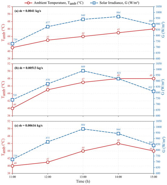
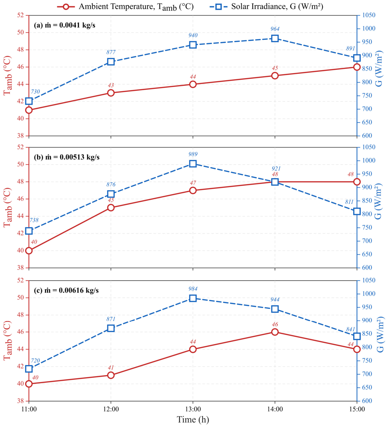
Figure 3 presents the variation in ambient temperature (Tamb) and solar irradiance (G) recorded during the experimental tests for three mass flow rates: = 0.00410 kg s−1, = 0.00513 kg s−1, and = 0.00616 kg s−1. In all three cases, the solar irradiance follows a characteristic bell-shaped profile, rising to a peak around 13:00–14:00 before declining in the afternoon. The maximum irradiance recorded reached 975 W m−2 at 13:00 for = 0.00513 kg s−1, while values of 964 and 959 W m−2 were observed for = 0.00410 and = 0.00616 kg s−1, respectively.
Figure 3.
Variation in ambient temperature and solar radiation intensity during the test days.
The ambient temperature increased gradually throughout the morning, reaching maximum values between 45 °C and 48 °C at 14:00 across the three cases. A slight variation is observed between mass flow conditions, attributable to the different measurement days. These climatic inputs directly govern the thermal energy available to the absorber plate and consequently influence the outlet air temperature. The stable high-irradiance conditions confirm the suitability of the test site for evaluating the thermal performance of both the F-SAH and LB-SAH configurations.
4.2. CFD Model Validation
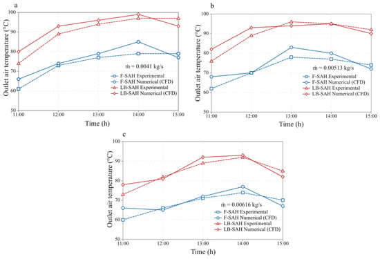
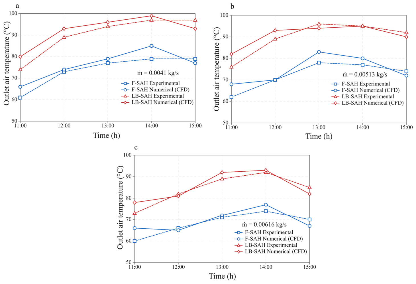
To assess the accuracy of the numerical model, Figure 4 compares the CFD-predicted outlet temperatures with the experimental measurements for both the F-SAH and LB-SAH at three mass flow rates. The CFD model generally reproduces the experimental trends, with an overall average deviation below 4.5%. A local maximum deviation of 9.1% is observed for the F-SAH at ṁ = 0.00616 kg s−1, mainly at the lowest experimental outlet temperature, where the measured value is 60 °C, and the predicted value is 66 °C. This localized deviation is attributed to the measurement at 11:00, which corresponds to the early collector operating period before the absorber plate reaches thermal equilibrium with the incident solar radiation, producing a transient heating behavior that is inherently inconsistent with the steady-state assumption of the numerical model. Similar early-morning deviations have been reported by El-Sebaey et al. [23] for comparable SAH configurations and attributed to the same physical mechanisms. It is important to note that the 9.1% deviation is an isolated outlier confined to a single operating point; across all midday and afternoon hours, which constitute the dominant useful operating window of the collector, deviations remain low. For the LB-SAH at the same flow rate, the deviations generally remain below 6.4%. Similar average deviations were reported by Amara et al. [17] for comparable SAH configurations simulated with the SST k–ω turbulence model. The larger discrepancies observed during the early and late hours are likely caused by transient thermal inertia and outdoor climatic fluctuations, including wind and humidity variations, which are not fully represented in the quasi-steady numerical simulations.
Figure 4.
Comparison of numerical results with experimental data for outlet temperature for both SAHs at different mass flow rates: (a) = 0.00410 kg s−1, (b) = 0.00513 kg s−1, and (c) = 0.00616 kg s−1.
4.3. Temperature, Velocity, and Pressure Distributions
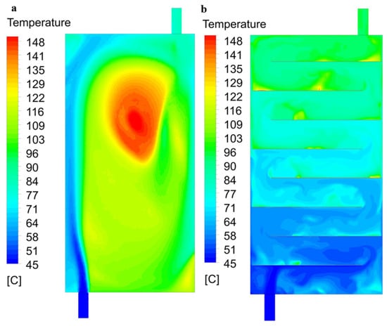
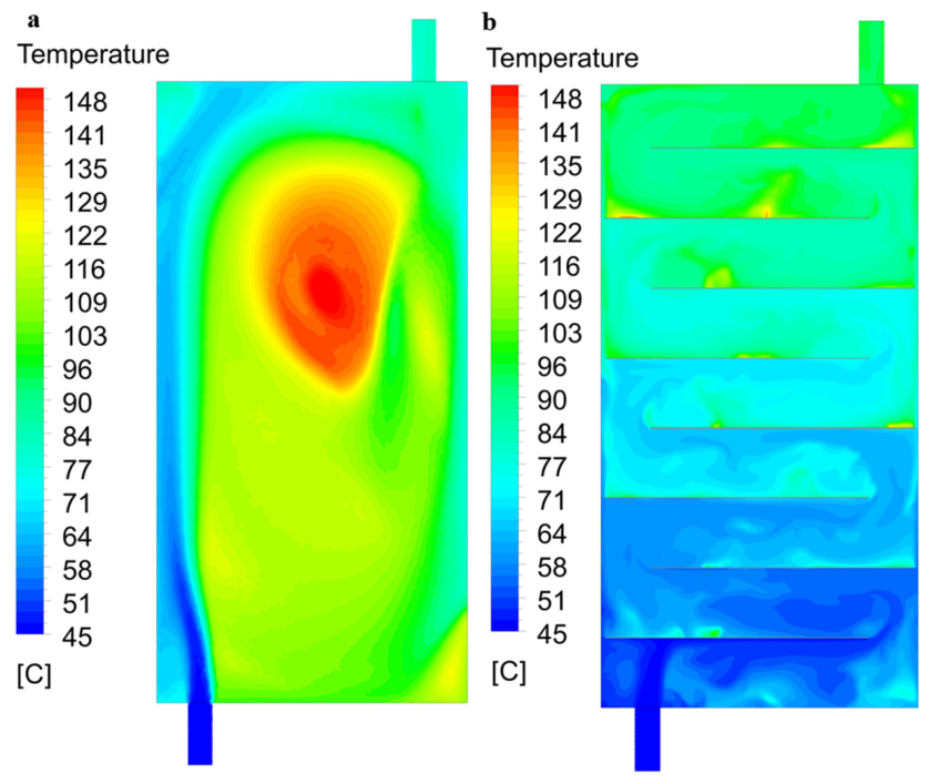
Figure 5 illustrates the temperature contour distributions inside the F-SAH and LB-SAH obtained from CFD simulations. Air temperature increases progressively as the fluid travels from the inlet to the outlet in both configurations. The maximum air temperature in the F-SAH reaches 79 to 85 °C at = 0.00410 kg s−1, concentrated in the central outlet region. In contrast, the LB-SAH produces outlet temperatures between 93 and 99 °C under the same flow conditions, with the highest temperatures observed along the upper passages, where the air has accumulated the most heat from the absorber plate. This superior thermal performance of the LB-SAH is attributed to the serpentine flow-path geometry, which forces the air to travel a significantly longer effective path length than that in the flat configuration. The extended contact time between the flowing air and the heated absorber surface enhances convective heat transfer, leading to higher outlet temperatures. This observation aligns with the findings of Wang [16], who demonstrated that serpentine airflow configurations yield outlet temperatures up to 27 K higher than those of conventional collectors.
Figure 5.
Temperature distribution in (a) F-SAH and (b) LB-SAH.
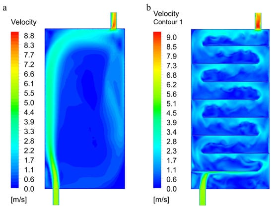
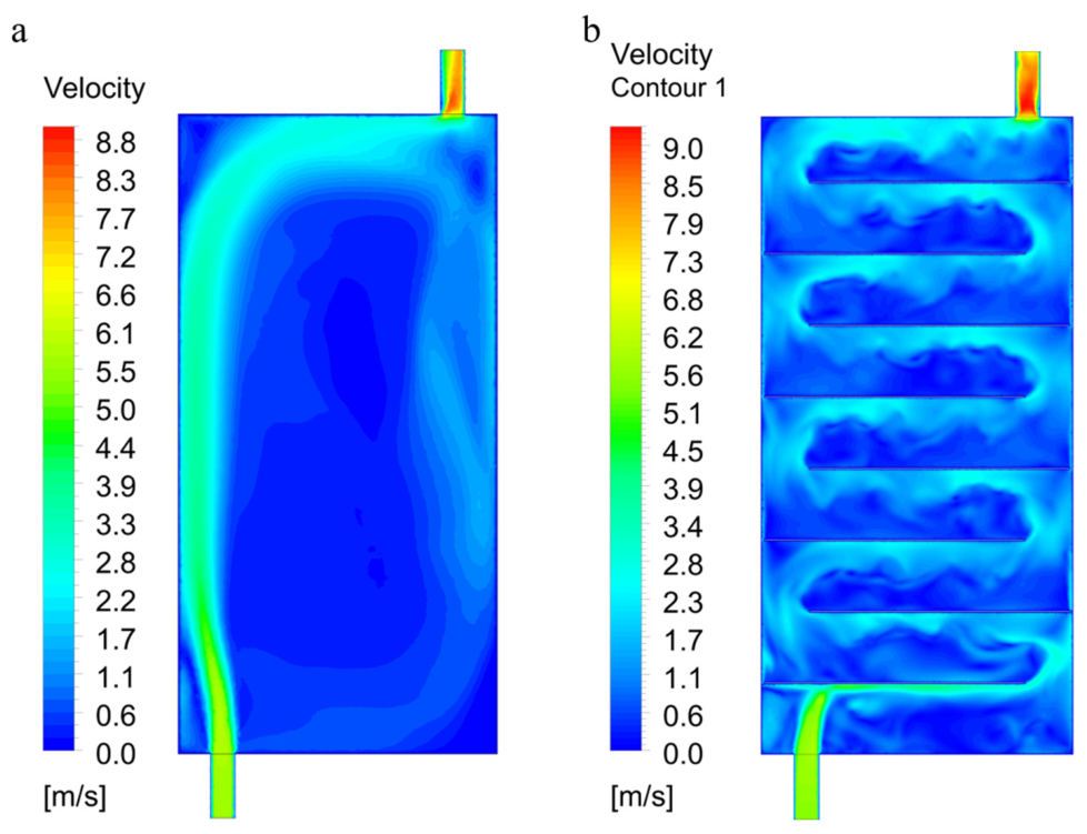
Figure 6 shows the velocity contour distributions in the XY plane at the mid-height plane for both SAHs. A high-velocity jet is observed at the inlet of both systems. As the airflow spreads into the duct network, the velocity decreases to around 5–8 m s−1 within the main flow passages. A critical distinction between the two geometries is observed at the bend regions: in the F-SAH, L-shaped bends produce moderate velocity peaks of approximately 12 m s−1, whereas the U-shaped bends of the LB-SAH generate local velocity peaks exceeding 16.5 m s−1. These higher velocities at the U-bends intensify fluid-mixing and enhance convective heat transfer coefficients, which explains the superior thermal output of the LB-SAH. However, they also contribute to greater pressure losses, as discussed in the following section.
Figure 6.
Velocity distribution in (a) F-SAH and (b) LB-SAH.
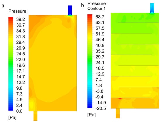
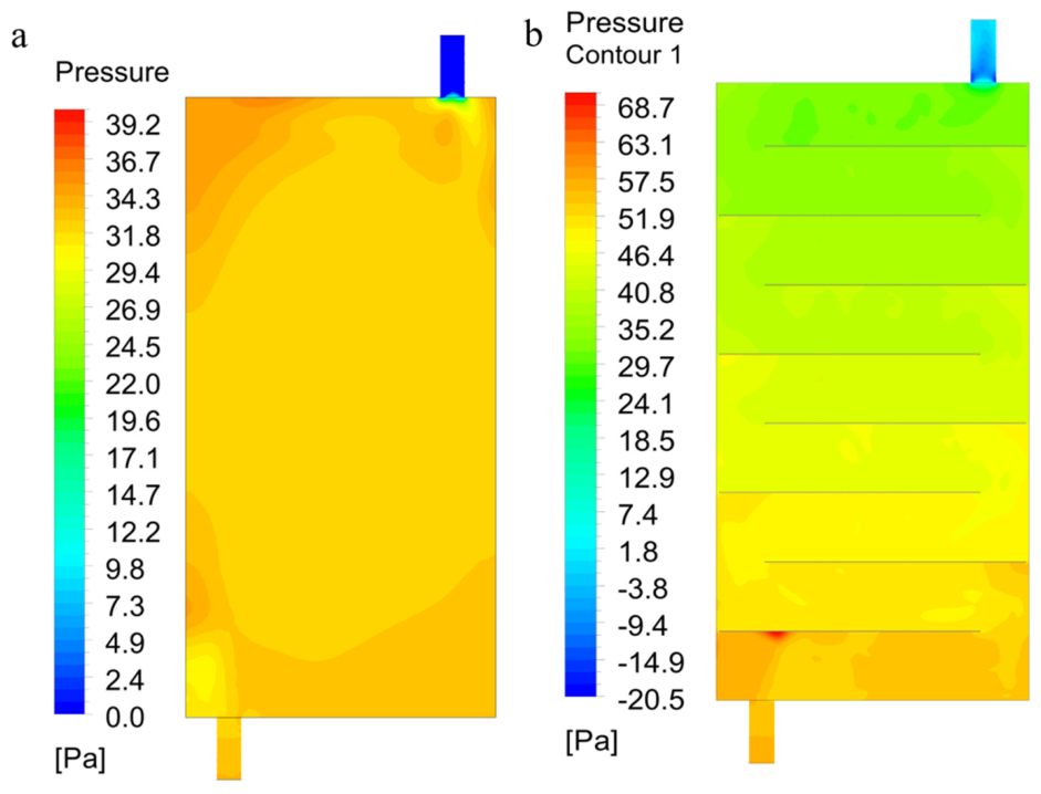
Figure 7 presents the pressure contour distributions for both SAH configurations. A continuous pressure drop from inlet to outlet is observed in both systems, consistent with the expected behavior of forced convection in confined duct networks. LB-SAH exhibits a pressure loss nearly twice as large as that of the F-SAH, a direct consequence of the greater flow resistance imposed by the multiple U-shaped bends in the serpentine configuration. As the mass flow rate increases from = 0.00410 to 0.00616 kg s−1, the pressure losses in both systems increase substantially due to the higher airflow velocities. The LB-SAH consistently exhibits pressure losses approximately 1.8–2.0 times greater than those of the F-SAH across all tested flow rates. While the LB-SAH achieves higher outlet temperatures, the significantly elevated pressure losses translate directly into higher fan power requirements. This trade-off between thermal gain and hydraulic penalty is a central design consideration for solar air heater optimization and underpins the thermohydraulic performance evaluation presented in the following section.
Figure 7.
Pressure contours in (a) F-SAH and (b) LB-SAH.
4.4. Thermal Performance and Thermohydraulic Analysis
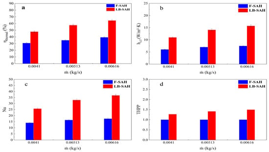
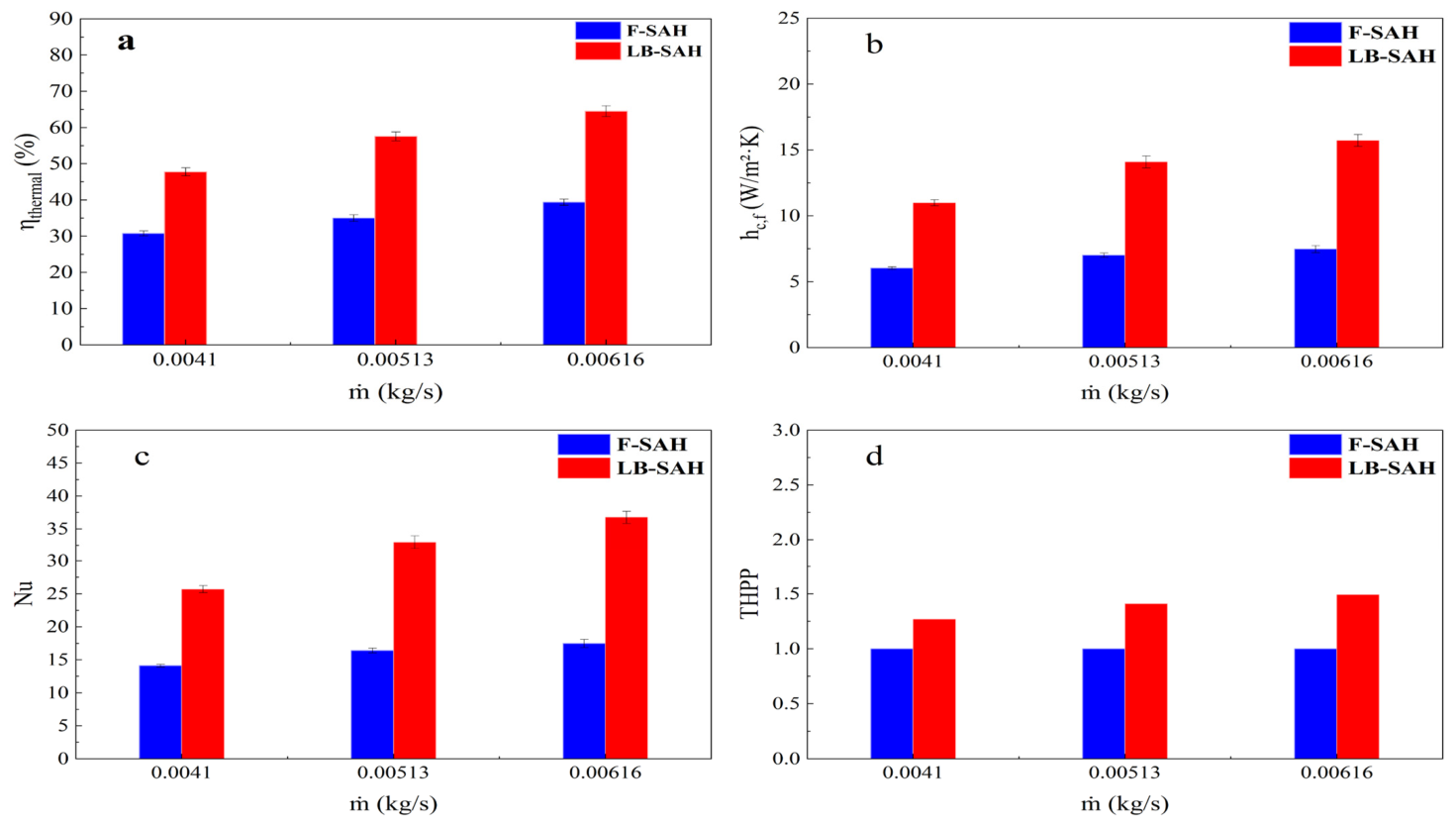
Figure 8 summarizes the key thermal and thermohydraulic performance parameters as a function of mass flow rate for both the F-SAH and LB-SAH at three mass flow rates of = 0.00410, 0.00513, and 0.00616 kg s−1, respectively. As shown in Figure 8a, the thermal efficiency () of both SAH configurations increases monotonically with mass flow rate. LB-SAH achieves thermal efficiencies of 47.76%, 57.56%, and 64.51% at = 0.00410, 0.00513, and 0.00616, respectively, representing improvements of 55.25%, 64.50%, and 63.86% over the corresponding F-SAH values of 30.77%, 34.99%, and 39.37%. This enhancement is primarily attributed to the increased heat extraction capability of the zig-zag flow path, which extends the residence time of the air within the collector and maximizes the absorber-to-air heat transfer area.
Figure 8.
(a) Thermal efficiency , (b) heat transfer coefficient (h), (c) Nusselt number (Nu), and (d) thermohydraulic performance parameter (THPP) for F-SAH and LB-SAH.
The convective heat transfer coefficient (h), shown in Figure 8b, follows the same increasing trend with for both systems. The LB-SAH yields h values of 10.99, 14.09, and 15.72 W m−2 K−1 at the three mass flow rates, compared to 6.04, 7.02, and 7.48 W m−2 K−1 for the F-SAH. The LB-SAH therefore achieves heat transfer coefficients 1.82–2.1 times those of the F-SAH, a direct consequence of the higher fluid velocities at the U-bends and the longer effective flow path, both of which intensify convective heat transfer. This behavior is also reflected in the Nusselt number (Figure 8c): the LB-SAH achieves Nu values of 25.71, 32.95, and 36.76, compared to 14.12, 16.41, and 17.49 for the F-SAH, representing enhancements of 82.05%, 100.78%, and 110.18%, respectively.
The THPP presented in Figure 8d provides an integrated measure of both the thermal gain and the hydraulic penalty associated with each configuration. The THPP increases with mass flow rate for both SAHs, rising from 1.27 at = 0.00410 to 1.41 at = 0.00513 kg s−1, and reaching 1.49 at 0.00616 kg s−1. Values of THPP across all operating conditions confirm that the LB-SAH configuration delivers a substantial net energy benefit relative to that of the conventional F-SAH, despite the increased pressure losses. The progressive rise in THPP with indicates that operating at higher mass flow rates is energetically advantageous for both designs.
While the LB-SAH demonstrates clear thermal superiority over the F-SAH across all tested conditions, this performance gain is accompanied by substantially greater pressure losses, and the practical implications of this trade-off warrant explicit discussion. At the highest mass flow rate (ṁ = 0.00616 kg s−1), the pressure drop across the LB-SAH is approximately twice that of the F-SAH, resulting in a pumping power requirement that is similarly doubled. For a small-scale domestic collector of the present dimensions, the absolute pumping power remains low, on the order of a few watts, and is unlikely to represent a prohibitive energy penalty in practice. However, at larger scale or higher mass flow rates, the cumulative fan-power demand becomes a more significant fraction of the useful thermal output and must be carefully evaluated in any system-level energy balance.
The THPP does not directly quantify the absolute pumping power in watts or its proportion of the total useful heat gain, and therefore provides an incomplete picture of practical energy economics on its own. A more complete assessment is provided by the effective thermal efficiency. When evaluated on this basis, the LB-SAH retains a meaningful efficiency advantage over the F-SAH across the full range of tested mass flow rates, confirming that the additional pressure penalty does not negate the thermal gain under the present operating conditions. Nevertheless, the margin between thermal benefit and hydraulic penalty narrows as mass flow rate increases, and the crossover point, beyond which the pumping power penalty begins to erode the net advantage of the LB-SAH, should be identified in future work through extended testing at higher mass flow rates. For applications in which fan power is severely constrained, the F-SAH remains the more energy-balanced choice, while the LB-SAH is recommended when maximizing outlet temperature and thermal efficiency is the primary design objective.
5. Limitations and Scope of Applicability
While the present study provides a validated experimental and numerical comparison of the F-SAH and LB-SAH configurations, several limitations should be acknowledged to contextualize the applicability of the findings. The experimental measurements were conducted over a restricted testing period under the specific climatic conditions of the study site, with solar irradiance and ambient temperature values representative of a hot-arid Mediterranean climate during the tested season. These conditions may not reflect the full range of irradiance intensities, ambient temperatures, and atmospheric disturbances encountered in other geographic locations or across different seasons. In particular, winter operating conditions are expected to yield lower absolute outlet temperatures and thermal efficiencies for both configurations, though the relative performance advantage of the LB-SAH over the F-SAH is anticipated to be preserved, as it is primarily governed by flow path geometry rather than absolute irradiance level. In addition, the steady-state CFD framework adopted in the present study introduces localized deviations at early operating hours when transient thermal effects are significant, as discussed in Section 4.2. A transient simulation approach incorporating time-varying solar irradiance and ambient temperature boundary conditions would improve the fidelity of the numerical predictions across the full daily operating cycle and is recommended for future investigation.
6. Conclusions
This study presented a comprehensive experimental and numerical comparative analysis of F-SAH and LB-SAH configurations under real outdoor conditions at three mass flow rates. A validated three-dimensional CFD model achieved an average deviation of 4.5% relative to the experimental measurements. The principal findings are summarized below:
- (i)
- The LB-SAH achieved a maximum CFD-predicted outlet temperature of 99 °C compared to 85 °C for the F-SAH at m = 0.00410 kg s−1, an improvement of approximately 16%.
- (ii)
- The thermal efficiency of the LB-SAH ranged from 47.76% to 64.51% across the tested mass flow rates, representing improvements of 55–64% over the corresponding F-SAH efficiencies of 30.77% to 39.37%.
- (iii)
- The Nusselt number (Nu) and convective heat transfer coefficient (h) of the LB-SAH were consistently 1.8–2.1 times higher than those of the F-SAH. At the highest mass flow rate, the LB-SAH achieved Nu = 36.76 and h = 15.72 W m−2 K−1, compared to Nu = 17.49 and h = 7.48 W m−2 K−1 for the F-SAH.
- (iv)
- The THPP increased from 1.27 to 1.49 with increasing mass flow rate, confirming that the thermal gain of the LB-SAH outweighs its associated pressure-loss penalty across all tested conditions.
These results demonstrate that absorber flow-path geometry has a significant influence on SAH performance and provide quantitative benchmarks for the comparative design and selection of flat versus longitudinal-baffle absorber configurations. Future work should examine the performance of these configurations at different tilt angles and under seasonal climatic conditions, incorporating phase change materials or porous inserts to further enhance thermal storage and heat transfer.
Author Contributions
Data curation, M.H.A. and M.A.A.; formal analysis, F.M.S. and M.A.A.; methodology, F.M.S., M.F.A., S.H. and S.A.H.; writing—original draft, F.M.S., M.A.A. and M.H.A.; writing—review and editing, S.A.H., N.R., S.Y. and M.F.A.; funding acquisition, S.Y. and N.R.; language editing and manuscript revision were performed by S.Y. All authors have read and agreed to the published version of the manuscript.
Funding
This work was supported and funded by the Deanship of Scientific Research at Imam Mohammad Ibn Saud Islamic University (IMSIU) (grant number IMSIU-DDRSP2603).
Data Availability Statement
The original contributions presented in this study are included in the article. Further inquiries can be directed to the corresponding author.
Acknowledgments
During the preparation of this work, the authors used ChatGPT (GPT-5.6 Luna, OpenAI, USA) to support the writing process by refining grammar and enhancing clarity. After using this tool, the authors reviewed and edited the content as needed and take full responsibility for the content of the published article.
Conflicts of Interest
The authors declare no conflict of interest.
References
- Shaaban, F.M.; Abdel-Salam, M.F.; Farroh, K.Y.; Wang, H.; Atia, M.F. Thermal Performance Analysis of an Indirect Solar Cooker Using a Graphene Oxide Nanofluid. Sustainability 2024, 16, 2539. [Google Scholar] [CrossRef] [Scilit]
- Zhang, T.; Abdelhamid, M.A.; Ahmed, M.E.A.E.; Shaaban, F.; Makram, S.O.; Zhang, Z.; Abdelkader, T.K. Energy, Exergy, Environmental, and Economic (4E) Analysis of an Indirect Solar Cooker. Case Stud. Therm. Eng. 2025, 71, 106249. [Google Scholar] [CrossRef] [Scilit]
- Abdelhamid, M.A.; Abdelkader, T.K.; Sayed, H.A.A.; Zhang, Z.; Zhao, X.; Atia, M.F. Design and Evaluation of a Solar Powered Smart Irrigation System for Sustainable Urban Agriculture. Sci. Rep. 2025, 15, 11761. [Google Scholar] [CrossRef] [Scilit]
- Abdelhamid, M.A.; Mahmoud, S.M.; El-Nasr, M.K.A.; Zhang, Z.; Hendy, Z.M. Sustainable Hydroponic Production Using Solar Energy and Treated Greywater within the Water-Energy-Food-Environment Nexus. Sci. Rep. 2025, 15, 31200. [Google Scholar] [CrossRef] [Scilit]
- Abdelkader, T.K.; Fan, Q.; Gaballah, E.S.; Wang, S.; Zhang, Y. Energy and Exergy Analysis of a Flat-Plate Solar Air Heater Artificially Roughened and Coated with a Novel Solar Selective Coating. Energies 2020, 13, 997. [Google Scholar] [CrossRef] [Scilit]
- Abdelkader, T.K.; Zhang, Y.; Gaballah, E.S.; Wang, S.; Wan, Q.; Fan, Q. Energy and Exergy Analysis of a Flat-Plate Solar Air Heater Coated with Carbon Nanotubes and Cupric Oxide Nanoparticles Embedded in Black Paint. J. Clean. Prod. 2020, 250, 119501. [Google Scholar] [CrossRef] [Scilit]
- Al-Chlaihawi, K.; Al-Farhany, K.; Abdulkadhim, A. A Comparative Investigation of Thermo-Hydraulic Performance in a Solar Air Heater Roughened with Quarter Petal Shaped Ribs. Int. J. Therm. Sci. 2026, 223, 110580. [Google Scholar] [CrossRef] [Scilit]
- Saeed, M.M.A.; Alfahham, M.; Hammoodi, K.A.; Kadhim, S.A.; Youssif, Y.F. Energy and Exergy Analysis of Solar Air Heaters: A Focused Review. Heat Transf. 2026, 55, 56–79. [Google Scholar] [CrossRef] [Scilit]
- Markam, B.; Maiti, S. Artificial Enhancer for Small-Scale Solar Air Heater—A Comprehensive Review. Clean. Energy Syst. 2023, 4, 100046. [Google Scholar] [CrossRef] [Scilit]
- Salarpour, N.; Azadani, L.N. Optimization and Evaluation of Thermo-Hydraulic Performance of Solar Air Heaters Equipped with Different Roughness Geometries. Case Stud. Therm. Eng. 2024, 61, 105037. [Google Scholar] [CrossRef] [Scilit]
- Jin, D.; Quan, S.; Zuo, J.; Xu, S. Numerical Investigation of Heat Transfer Enhancement in a Solar Air Heater Roughened by Multiple V-Shaped Ribs. Renew. Energy 2019, 134, 78–88. [Google Scholar] [CrossRef] [Scilit]
- Azadani, L.N.; Gharouni, N. Multi Objective Optimization of Cylindrical Shape Roughness Parameters in a Solar Air Heater. Renew. Energy 2021, 179, 1156–1168. [Google Scholar] [CrossRef] [Scilit]
- Kumar, A.; Layek, A. Energetic and Exergetic Based Performance Evaluation of Solar Air Heater Having Winglet Type Roughness on Absorber Surface. Sol. Energy Mater. Sol. Cells 2021, 230, 111147. [Google Scholar] [CrossRef] [Scilit]
- Amara, W.B.; Bouabidi, A.; Chrigui, M. Thermal Performance Improvement of a Spiral Channel Solar Air Heater: Numerical and Experimental Investigation in the Desert Climate of Gabes Region. J. Sol. Energy Eng. Trans. ASME 2024, 146, 031007. [Google Scholar] [CrossRef] [Scilit]
- Sari, A.; Sadi, M.; Sabet, G.S.; Mohammadiun, M.; Mohammadiun, H. Experimental Analysis and Exergetic Assessment of the Solar Air Collector with Delta Winglet Vortex Generators and Baffles. J. Therm. Anal. Calorim. 2020, 145, 867–885. [Google Scholar] [CrossRef] [Scilit]
- Wang, L. Research on the Collect Heat Performance of New Type Collector. Energy Sources Part Recovery Util. Environ. Eff. 2022, 44, 9412–9427. [Google Scholar] [CrossRef] [Scilit]
- Amara, W.B.; Bouabidi, A.; Chrigui, M.; Cuce, E. A Comparative Study of Helical and Spiral Flow Paths in Solar Air Heaters: Experimental Testing and CFD Modeling. Renew. Energy 2025, 244, 122642. [Google Scholar] [CrossRef] [Scilit]
- Li, D.; Bai, Z.; Samad, S.; Abed, A.M.; Li, Y.; Alhumaid, S.; Dutta, A.K.; Alkhalaf, S.; Khan, M.N.; Ali, H.E. Deep Learning-Based Prediction of Thermal-Hydraulic and Exergy Performance in a Novel Bidirectional Wavy Absorber Solar Air Heater. Renew. Energy 2026, 256, 124192. [Google Scholar] [CrossRef] [Scilit]
- Newar, P.P.; Das, B.; Pandit, S. Thermal Optimization and Predictive Modeling of a Solar Air Heater with Combined Rectangular and Semi-Circular Ribs Using CFD and ANN-PSO Techniques with Experimental Validation. Int. J. Heat Fluid Flow 2026, 121, 110617. [Google Scholar] [CrossRef] [Scilit]
- Mund, C.; Rathore, S.K.; Sahoo, R.K. Analysis of Solar Air Heaters Based on Computational Fluid Dynamics. J. Therm. Anal. Calorim. 2024, 149, 1831–1857. [Google Scholar] [CrossRef] [Scilit]
- Prasad, J.S.; Datta, A.; Dewan, A.; Mondal, S. Solar Air Heater Roughened with Chamfered Grooves: Thermal Enhancement and Entropy Minimization. Energy 2024, 313, 133958. [Google Scholar] [CrossRef] [Scilit]
- Wang, X.; Zhang, L.; Chang, Y.; Song, Y.; Wang, L. Numerical Simulation Study on Heat Performance and Pressure Loss of Solar Air Heater with Sinusoidal Baffles. AIMS Energy 2024, 12, 617–638. [Google Scholar] [CrossRef] [Scilit]
- El-Sebaey, M.S.; Ellman, A.; El-Din, S.S.; Essa, F.A. Thermal Performance Evaluation for Two Designs of Flat-Plate Solar Air Heater: An Experimental and CFD Investigations. Processes 2023, 11, 1227. [Google Scholar] [CrossRef] [Scilit]
- Chang, Y.; Xue, Y.; Geng, G. Effect of the Baffle’s Type on Thermal Performance of Solar Air Heaters. Case Stud. Therm. Eng. 2024, 59, 104580. [Google Scholar] [CrossRef] [Scilit]
- Afshari, F.; Sözen, A.; Khanlari, A.; Tuncer, A.D.; Şirin, C. Effect of Turbulator Modifications on the Thermal Performance of Cost-Effective Alternative Solar Air Heater. Renew. Energy 2020, 158, 297–310. [Google Scholar] [CrossRef] [Scilit]
- Amara, W.B.; Bouabidi, A.; Chrigui, M. Experimental Studies and 3D Simulations for the Investigation of Thermal Performances of a Solar Air Heater with Different Spiral-Shaped Baffles Heights. J. Build. Eng. 2023, 65, 105662. [Google Scholar] [CrossRef] [Scilit]
- Ngo, G.H.; Kumar, R.; Lee, D. Computational Fluid Dynamics Analysis of Heat Transfer and Fluid Flow Characteristics in Solar Air Heater Using Discrete Arc-Shaped Baffles. J. Therm. Anal. Calorim. 2025, 150, 16551–16567. [Google Scholar] [CrossRef] [Scilit]
- Kline, S. Describing Uncertainties in Single-Sample Experiments. Mech. Eng. 1963, 75, 3–8. [Google Scholar]
- Panda, S.; Kumar, R. Combined Effect of Solar Intensity and Air Mass Flow Rate on Inline Spherical Dimple Based Solar Air Heater during Summer Season. Sol. Energy 2023, 258, 156–174. [Google Scholar] [CrossRef] [Scilit]

Disclaimer/Publisher’s Note: The statements, opinions and data contained in all publications are solely those of the individual author(s) and contributor(s) and not of MDPI and/or the editor(s). MDPI and/or the editor(s) disclaim responsibility for any injury to people or property resulting from any ideas, methods, instructions or products referred to in the content. |
© 2026 by the authors. Licensee MDPI, Basel, Switzerland. This article is an open access article distributed under the terms and conditions of the Creative Commons Attribution (CC BY) license.