


Abstract
Bipolar plates are critical components in high-efficiency energy conversion devices such as electrolyzers, fuel cells, and flow batteries, and their durability directly affects the overall performance and lifespan of the system. Although graphite bipolar plates exhibit excellent electrical conductivity and corrosion resistance, their inherent brittleness and porous structure render them prone to thermal-stress-induced damage under dynamic temperature conditions. In this study, a self-designed thermal shock testing system was utilized to perform 16,000 cycles of accelerated aging tests on graphite bipolar plates, alternating between high-temperature (90 °C) and low-temperature (30 °C) water bath environments. Systematic analysis was conducted on the performance degradation behaviors under such thermal cycling conditions using multi-scale characterization techniques, including scanning electron microscopy (SEM), energy dispersive spectroscopy (EDS), electrical conductivity, contact angle, surface roughness, and corrosion current density analysis. The results demonstrate that the degradation in electrical conductivity, loss of hydrophobicity, and increased surface roughness were primarily attributed to thermal-stress-induced microcrack initiation and propagation, surface oxidation, and physical structural deterioration. Notably, the corrosion current density did not increase significantly after 16,000 thermal cycles, but slightly decreased in the later stage, indicating that the aging of graphite bipolar plates is dominated by physical fatigue damage, and the graphite matrix has excellent chemical stability. The novelty of this study lies in the construction of a thermal shock testing system under long-cycle conditions, revealing the synergistic mechanism of thermal cycle-induced performance degradation of graphite bipolar plates, which provides experimental evidence and theoretical guidance for the material selection, structural design, and protection strategies of highly durable bipolar plates.
1. Introduction
Against the background of the global efforts to promote carbon neutrality and energy transition, the large-scale deployment of renewable energy sources (e.g., wind and solar power) and the pursuit of green and low-carbon development have become a global consensus [1,2]. However, the inherent intermittency and volatility of renewable energy, coupled with the substantial carbon emissions associated with traditional energy systems, present core challenges to the realization of this objective. The key to addressing these challenges resides in efficient energy storage and low-carbon energy conversion technologies. Flow batteries, fuel cells, and electrolyzers have emerged as promising solutions, attracting growing academic and industrial attention with broad application prospects [3,4].
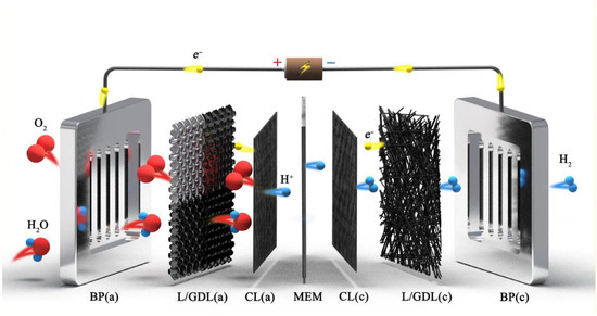
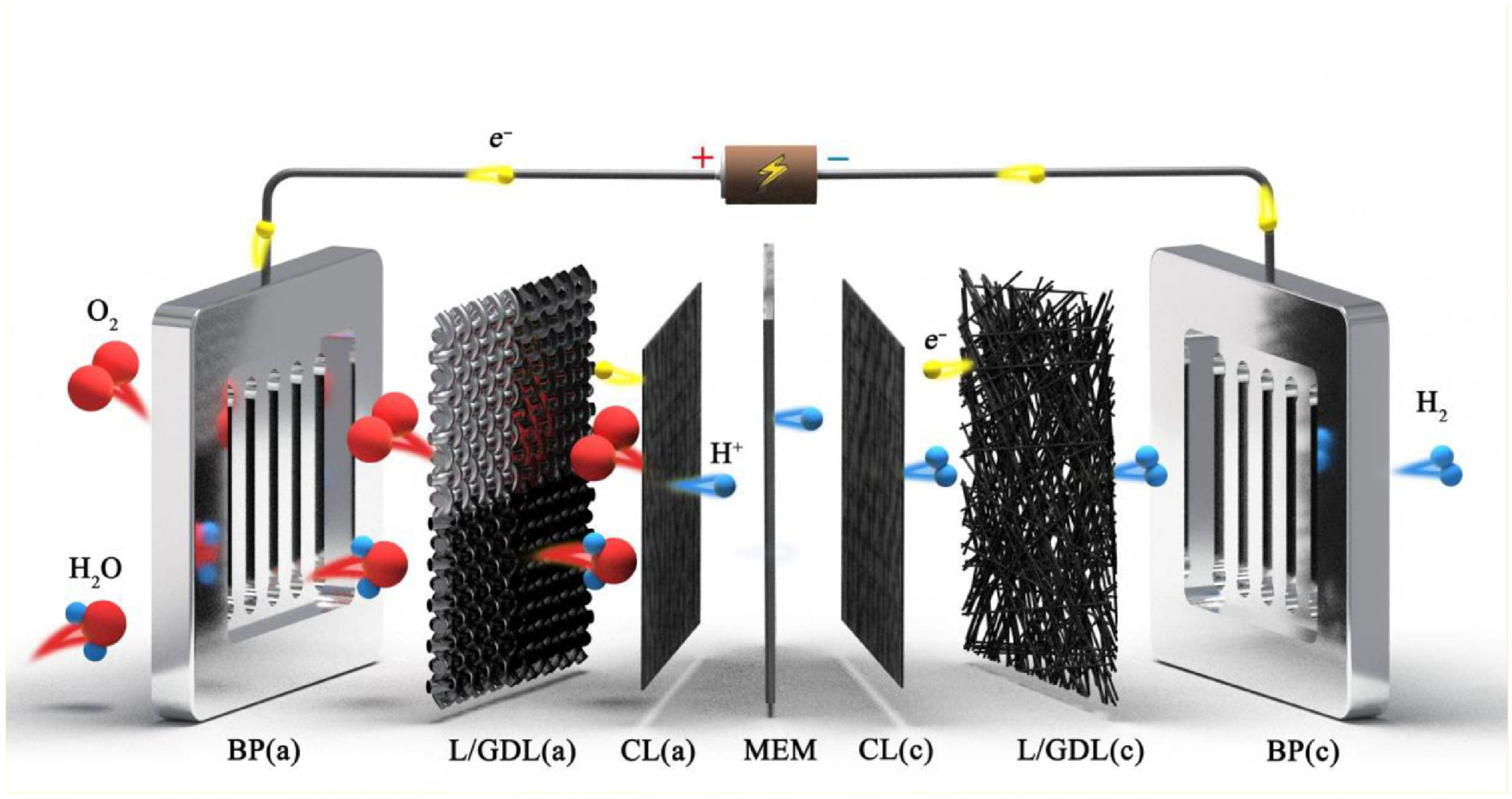
As a core component of such electrochemical devices, bipolar plates directly dictate the efficiency, cost, service life, and reliability of the entire system. In practical applications, bipolar plates perform functions such as conducting current, distributing reactant gases, removing reaction products, and providing mechanical support, as presented in Figure 1 [5]. Under actual operating conditions, bipolar plates are subjected to complex and dynamic environmental stresses, particularly in dynamic scenarios characterized by frequent start-stop cycles, power fluctuations, and ambient temperature variations, which expose the bipolar plates to varying degrees of thermal cycling [6]. During system startup, operation, and shutdown, bipolar plate materials can experience several tens of degrees temperature fluctuations. This is especially evident during cold starts in winter, where a rapid transition from low temperature to the system operating temperature is required within a short time [7]. Such unsteady thermal loads can generate significant thermal stress within the material. Due to differences in the coefficient of thermal expansion among material components, repeated thermal expansion and contraction can easily compromise the structural integrity of the bipolar plate. In severe cases, this may damage the surface integrity (particularly the coating on metallic bipolar plates), leading to a series of issues such as surface peeling, substrate oxidation, and increased interfacial contact resistance. Graphite bipolar plates offer excellent electrical conductivity and corrosion resistance, with a long history of application. However, their relatively low mechanical strength renders them more susceptible to structural damage under cyclic temperature conditions, significantly impacting their long-term operational reliability and stability.
Figure 1.
Schematic diagram of the bipolar plate (BP) functions in electrochemical devices [5] (This figure is licensed under CC BY-NC-ND 4.0).
Current research on bipolar plates predominantly focuses on material selection, coating development, and electrochemical corrosion resistance evaluation, emphasizing performance changes such as electrochemical stability and contact resistance under application conditions. Choe et al. [8] investigated the durability of graphite coatings on bipolar plates for vanadium redox flow batteries against electrochemical corrosion in strongly acidic electrolytes. They compared the durability, permeability, and area-specific resistance of two types of graphite with different physical properties: pyrolytic graphite and expanded flake-type graphite. Song et al. [9] reviewed the current research status regarding materials, fabrication, and applications of metallic, graphite, and composite bipolar plates for proton exchange membrane fuel cells. Metallic bipolar plates, typically fabricated from stainless steel or titanium alloys, are commonly subjected to surface modification: coatings (e.g., carbon-based or noble metal coatings) are applied to enhance corrosion resistance while reducing interfacial contact resistance [10,11,12,13]. Key research priorities in coating technology include optimizing coating processes to improve uniformity and stability—especially mitigating coating cracks and delamination induced by heterogeneous microstructures or residual stresses during stamping/forming processes. Another critical focus is the development of low-cost, corrosion-resistant coatings—particularly non-precious metal-based coatings that maintain excellent corrosion resistance while lowering production costs [14]. Additionally, coatings can enhance the water contact angle and alleviate fuel cell flooding. Feng et al. [15] demonstrated that the water contact angle of uncoated SS316L was significantly smaller than that of carbon-coated SS316L, confirming the superior hydrophobicity of carbon-coated SS316L.
Compared to metallic bipolar plates, graphite and graphite composite bipolar plates are widely employed in transportation and stationary power generation due to their superior durability and corrosion resistance, occupying a dominant position in the market—particularly in applications such as commercial vehicles where volumetric power density is less sensitive [16]. Their manufacturing process deviates from traditional metal machining methods. Owing to the inherently powdery nature and insufficient mechanical strength of graphite or carbon materials, a series of processes are required to convert them into dense, conductive components featuring gas flow channels. Techniques such as compression molding or injection molding are utilized to fabricate graphite blanks; however, these blanks inherently contain numerous microscopic interconnected pores. Consequently, impregnation treatment is indispensable to transform the porous, loose, and permeable blanks into dense, high-strength, and highly conductive final products. Notably, in contrast to dense, integrally formed metallic bipolar plates, graphite bipolar plates possess an inherent limitation: their internally heterogeneous porous structure is prone to inducing sealing defects. This can lead to gas crossover, leakage, and coolant penetration, which adversely affect the normal operation of devices such as fuel cells and flow batteries [17]. Particularly, coefficient of thermal expansion mismatches between different components renders them more susceptible to mechanical property degradation under thermal shock or fatigue-induced functional failure.
Thermal shock testing systems are core tools for evaluating thermal stability and optimizing the functions of carbon materials, with wide applications and remarkable results in activated carbon, graphite, carbon/carbon composites, and carbon-containing refractories. Sun et al. [18] treated activated carbon using programmable carbon thermal shock technology (1600 K pulse heating for 60 ms, cooling for 600 ms), achieving uniform dispersion of lead nanoparticles and selective removal of micropores through instantaneous thermal effects, which increased the high-rate partial state-of-charge cycle life of lead-carbon batteries from 5449 cycles to 18,139 cycles; Latella et al. [19] tested graphite using an arc-discharge thermal shock system (200–300 A input current, maximum temperature 1230 °C), revealing the law of thermal stress increasing with power, and confirming that its thermal shock fracture toughness increases from 0.8 MPa·m1/2 to 1.4 MPa·m1/2 at 220–420 °C. In the field of composites, Fu et al. [20] conducted tests through 1300 °C thermal cycling in Ar atmosphere (up to 20 cycles) and oxyacetylene ablation thermal shock (1800–1900 °C, up to 6 cycles), finding that the flexural strength and ablation resistance of HfC nanowire-reinforced carbon/carbon composites are significantly better than those of pure carbon/carbon composites; Chen et al. [21] and Luo et al. [22] verified through thermal shock tests at 1100 °C and 1373 K, respectively, that SiC whiskers and nano-BN can significantly improve the thermal stability and oxidation resistance of low-carbon carbon-containing refractories by promoting ceramic phase formation and releasing thermal stress. In addition, Wei et al. [23] adopted a muffle furnace-water cooling thermal shock scheme (100–400 °C holding for 2 h, 20 °C cooling for 1 min), clarifying the damage mechanism caused by water vapor scouring in pores of carbon composites under multiple thermal cycles. Most existing studies focus on a single performance or limited cycle numbers, with insufficient matching to the actual start-stop temperatures of electrochemical devices. The core components of electrochemical devices like fuel cells and electrolyzers under simulated realistic dynamic thermal cycling conditions remains scarce.
Therefore, this study focuses on the physicochemical aging mechanisms of bipolar plate materials in dynamic temperature environments. Through thermal shock tests coupled with multi-scale characterization techniques, including electrical conductivity testing, contact angle measurement, surface roughness analysis, corrosion study and surface morphology observation, the aging behavior of bipolar plates under alternating temperature conditions was systematically investigated. This research aims to elucidate the influence pathways of temperature cycling on the physical properties and surface characteristics of bipolar plate materials, thereby providing experimental data and theoretical basis for the material selection, structural design, and protective strategies of high-durability bipolar plate materials. Ultimately, this work seeks to guide the improvement of the durability under real-world operating conditions.
2. Experiment Design and Preparation
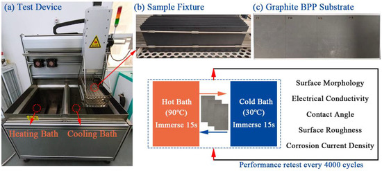
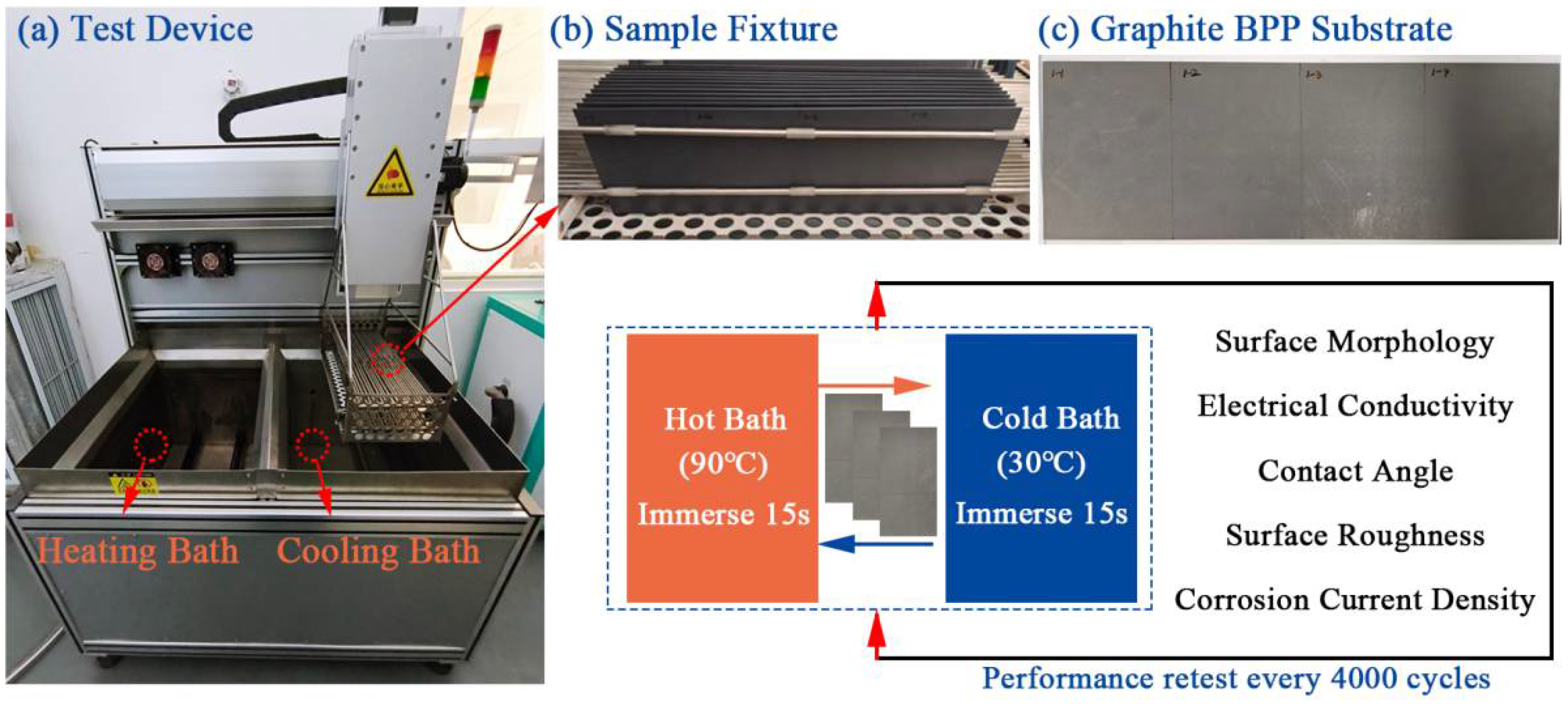
To systematically investigate the impact of temperature variations on the performance degradation of graphite bipolar plates, this study employed a self-designed thermal cycling test device for accelerated aging experiments. As shown in Figure 2, the test setup comprises a cold and a hot water bath, a drive motor, a high precision temperature control device, and an automatic program-controlled system. The device enables automatic cyclic switching of test samples between high temperature (90 °C) and low temperature (30 °C) water baths which simulates the working temperature range of fuel cell or electrolyzers.
Figure 2.
Schematic diagram of the experimental design: (a) Test setup; (b) Sample Fixture; (c) Bipolar plate substrate sample.
Graphite bipolar plate substrates were selected for this study, with one test cycle defined as transferring the sample from the low temperature bath to the high temperature bath and back to the low temperature bath. The graphite bipolar plate samples used were commercial products (Manufacturer: SUNKI Carbon Group China, Nantong, China), with approximate dimensions of 350 mm (length) × 12 mm (width) × 0.5 mm (thickness). The compressive strength is approximately 139 MPa, the open porosity was about 0.35%, and the bulk density was approximately 1.99 g/cm3. The temperature range of 30 °C to 90 °C was selected to represent the substantial thermal fluctuations that bipolar plates may experience during typical PEMFC/PEMEC start events and dynamic load changes. The test cycle conditions exhibit an accelerated aging effect to some extent. The immersion time in either the low or high temperature bath was set to 15 s, while each transfer between baths took approximately 13 s. The temperature control deviation throughout the experiments was maintained within ±2 °C. The total number of test cycles was set to 16,000. At intervals of 4000 cycles, samples were retrieved to characterize changes in key performance parameters, including electrical conductivity, contact angle, surface roughness, corrosion current density, and microscopic morphology (Hitachi, SU3800, Tokyo, Japan). To ensure experimental reproducibility, two parallel samples from the same production batch were tested. The schematic diagram of the entire experimental setup is presented in Figure 2.
The in-plane electrical conductivity was measured using a four-point probe system (ROOKO, model FT-541SJB-341, Ningbo, China). All measurements were conducted under controlled ambient conditions of 23 °C and 50% relative humidity in a constant temperature and humidity chamber to minimize the influence of moisture variation on contact resistance. The measurement uncertainty, estimated from instrument specifications and repeated tests, was within ±0.3%. The contact angle was measured using a contact angle goniometer (Dataphysics, OCA 15EC, Filderstadt, Germany) based on the sessile drop method. Each measurement was performed with a 4 μL droplet of deionized water, dispensed automatically and precisely via a microliter syringe. All tests were conducted in a controlled climate chamber maintained at 23 ± 2 °C and 50 ± 5% relative humidity to minimize the influence of ambient humidity on droplet evaporation. Surface roughness was measured using a Mahr MarSurf PS10 (Göttingen, Germany) surface roughness measuring instrument (Profile resolution: 8 nm). The corrosion current density test was conducted under the following conditions: an electrolyte solution of H2SO4 with pH = 3 containing 0.1 ppm F−, using a scanning potential of 1.0 V vs. Ag/AgCl reference electrode, with a one-hour potentiostatic corrosion test. The electrolyte was selected to simulate the acidic and potentially contaminant-containing environment within an operating PEMFC. The potentiostatic represents an anodic potential that can accelerate oxidation processes for evaluation purposes.
3. Results and Discussion
3.1. Effect of Thermal Shock on Surface Morphology
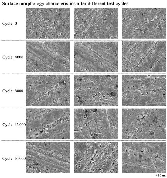
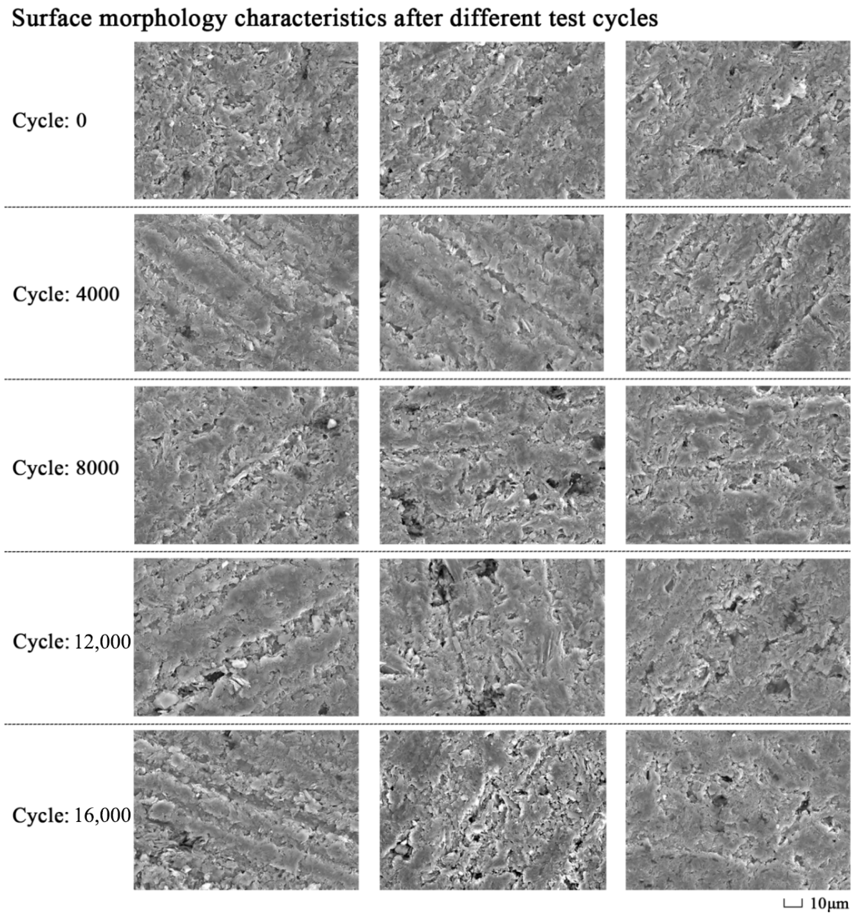
The impact of thermal shock on bipolar plates stems from the accumulation of thermal stress induced by temperature gradients, ultimately resulting in structural damage, surface performance degradation, and functional failure of the plates. Scanning Electron Microscopy (SEM) [24] enables clear visualization of the surface damage evolution of graphite bipolar plates under thermal shock conditions, as depicted in Figure 3. At the initial stage (0–4000 cycles), a dispersed band-like microcrack network emerged on the sample surface, with crack widths predominantly ranging from 0 to 5 μm. As the number of cycles increased to 8000, the crack bands further expanded in both width and depth, with maximum crack widths reaching 10 μm. At this stage, localized spalling started to occur on the surface, with the spalled regions ranging approximately 10–20 μm in size. In the 12,000–16,000 cycle stage, surface damage aggravated, with large-scale spalled areas forming and the size and depth of crack pores further increasing.
Figure 3.
The surface morphology characteristics of the bipolar plate after various test cycles, presenting band-like propagation of microcracks and crack hole damage.
Under thermal shock, resin and graphite particles undergo differential expansion and contraction owing to their distinct coefficients of thermal expansion. This induces shear stress at the two-phase interface; under repeated thermal cycling, this stress causes a reduction in interfacial bonding strength, leading to slight interfacial debonding. This accounts for the initial formation of the band-like microcracks observed via SEM.
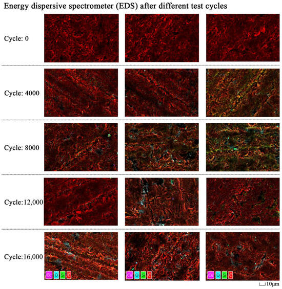
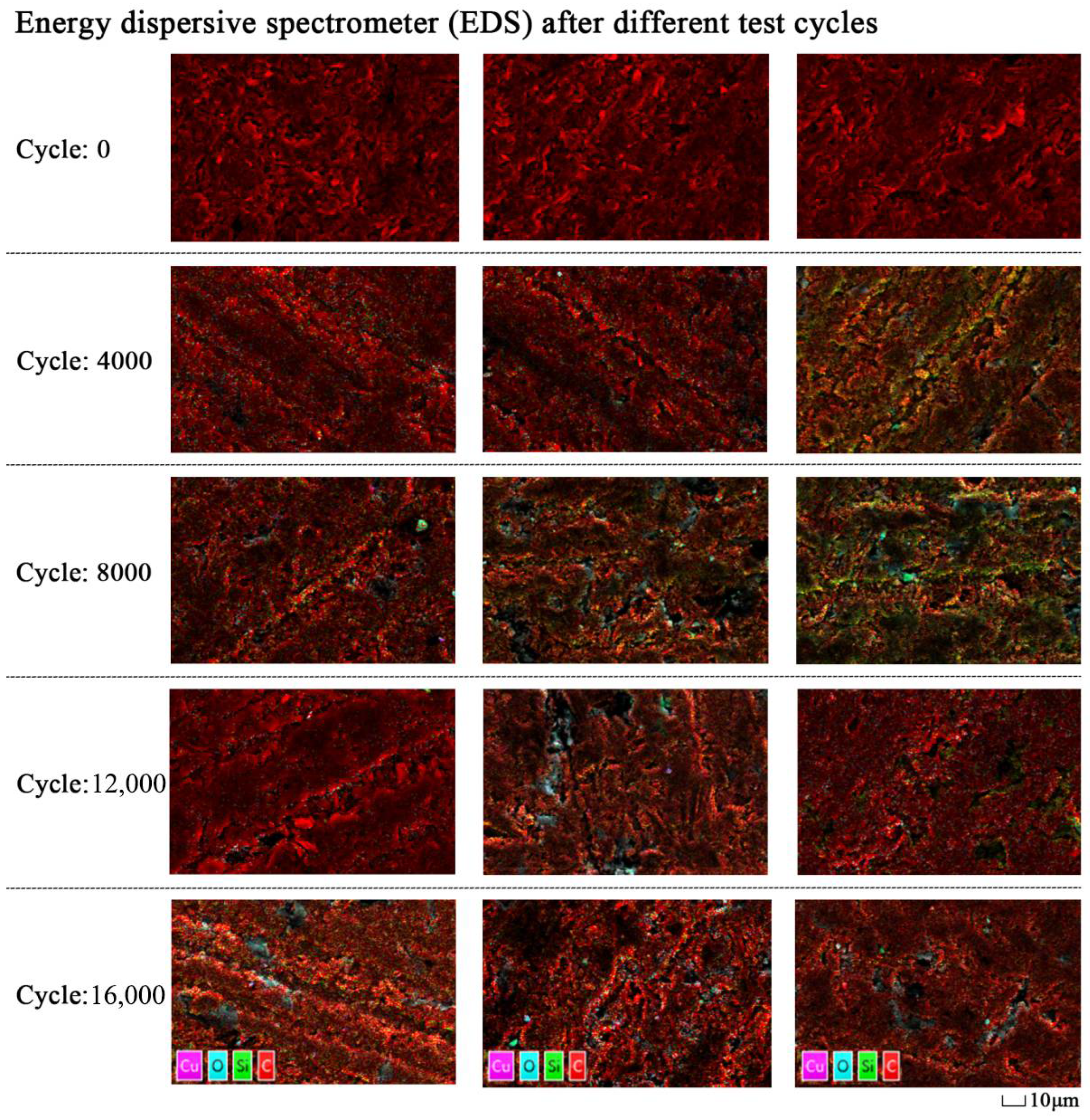
Energy Dispersive Spectroscopy (EDS) enables rapid characterization of the elemental composition, relative elemental content, and spatial distribution of elements in a sample [25]. In this study, EDS analysis was performed on samples subjected to different thermal cycle counts, with representative results shown in Figure 4. At the initial stage (0 cycles), the sample was composed of 100% carbon (C) as the primary element, with no other elements detected. As the experiment progressed, a distinct increase in oxygen (O) content was observed: after 4000 thermal cycles, the surface oxygen content reached 3.59 wt%; following 8000 cycles, more prominent oxidation features were observed, with the oxygen content further increasing to 4.25 wt%. This evolution of elemental composition demonstrates that the degree of surface oxidation gradually deepens with increasing thermal cycles.
Figure 4.
EDS-based oxygen distribution maps of the bipolar plate after various test cycles, revealing that oxygen was significantly enriched at the crack edges and spalling areas.
Notably, oxygen was significantly enriched at crack edges and spalled regions. EDS analysis demonstrated that the oxygen content in regions with dense microcracks was significantly higher than that in the normal regions, confirming that oxidation reactions preferentially take place at defect sites.
3.2. Effect of Thermal Shock on Electrical Conductivity
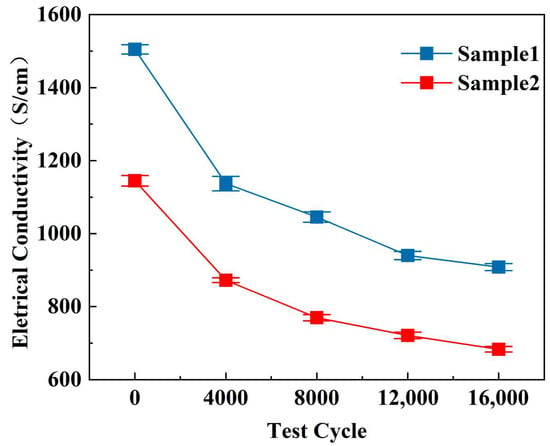
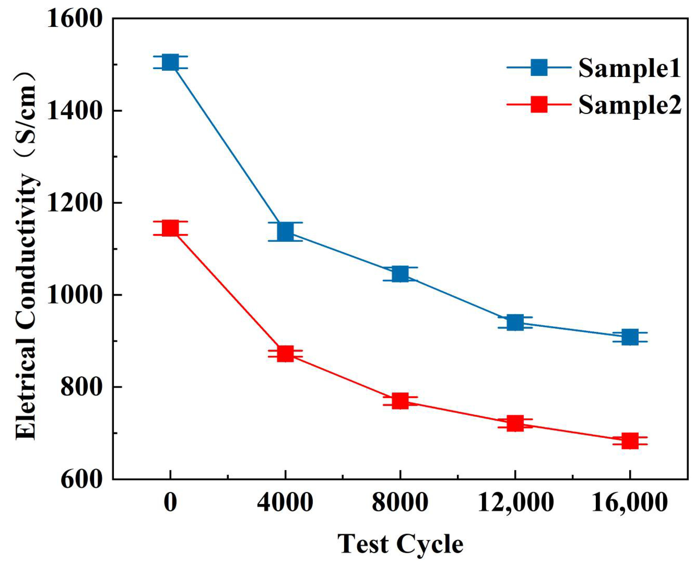
Figure 5 presents the variations in electrical conductivity of the bipolar plates following every 4000 thermal cycles. Both samples showed substantial degradation in electrical conductivity, exhibiting three distinct stages of decline. In the initial stage (0–4000 cycles), the degradation rate was the fastest, with Sample 1 and Sample 2 experiencing a reduction of 24.4% and 24.8%, respectively, indicating that the material’s electrical conductivity is highly sensitive to initial thermal shocks. Subsequent to the initial stage, the degradation rate slowed during the middle phase (4000–12,000 cycles), where Sample 1 and Sample 2 underwent a further reduction of 16.9% and 12.9%, respectively, entering a period of stable degradation. In the late stage (12,000–16,000 cycles), the degradation rate slowed down further, with Sample 1 and Sample 2 exhibiting a reduction of 3.4% and 5.3%, respectively, suggesting a gradual stabilization of electrical conductivity.
Figure 5.
Changes in electrical conductivity of the bipolar plates after every 4000 thermal-shock cycles.
The reduction in electrical conductivity of graphite bipolar plates following thermal shock is attributed to the synergistic effects of “physical damage” and “chemical erosion.” Firstly, the propagation of thermal stress-induced microcracks during thermal cycling is a primary factor contributing to the reduction in electrical conductivity. Under cyclic thermal loading, the expansion of the porous structure in the graphite material disrupts conductive pathways and elevates electron transport resistance.
Furthermore, the formation of a surface oxide layer contributes significantly to the degradation of electrical conductivity. During the high-temperature stages, the graphite material and resin binder undergo oxidation reactions with oxygen and moisture, forming poorly conductive or non-conductive oxide layers that introduce additional interfacial resistance. The thickness of the oxide layer increases with the cycle count, further exacerbating the reduction in electrical conductivity. These physical and chemical damage mechanisms are further corroborated by the SEM and EDS characterization results.
3.3. Effect of Thermal Shock on Contact Angle
The contact angle is primarily used to characterize the surface hydrophilicity or hydrophobicity of graphite bipolar plates under different thermal cycling conditions, and is of great practical significance for water management in electrolysis reactions or water drainage processes in fuel cells.
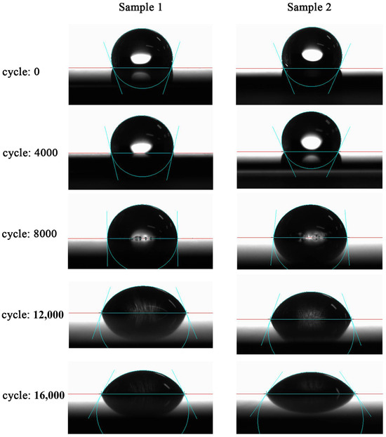
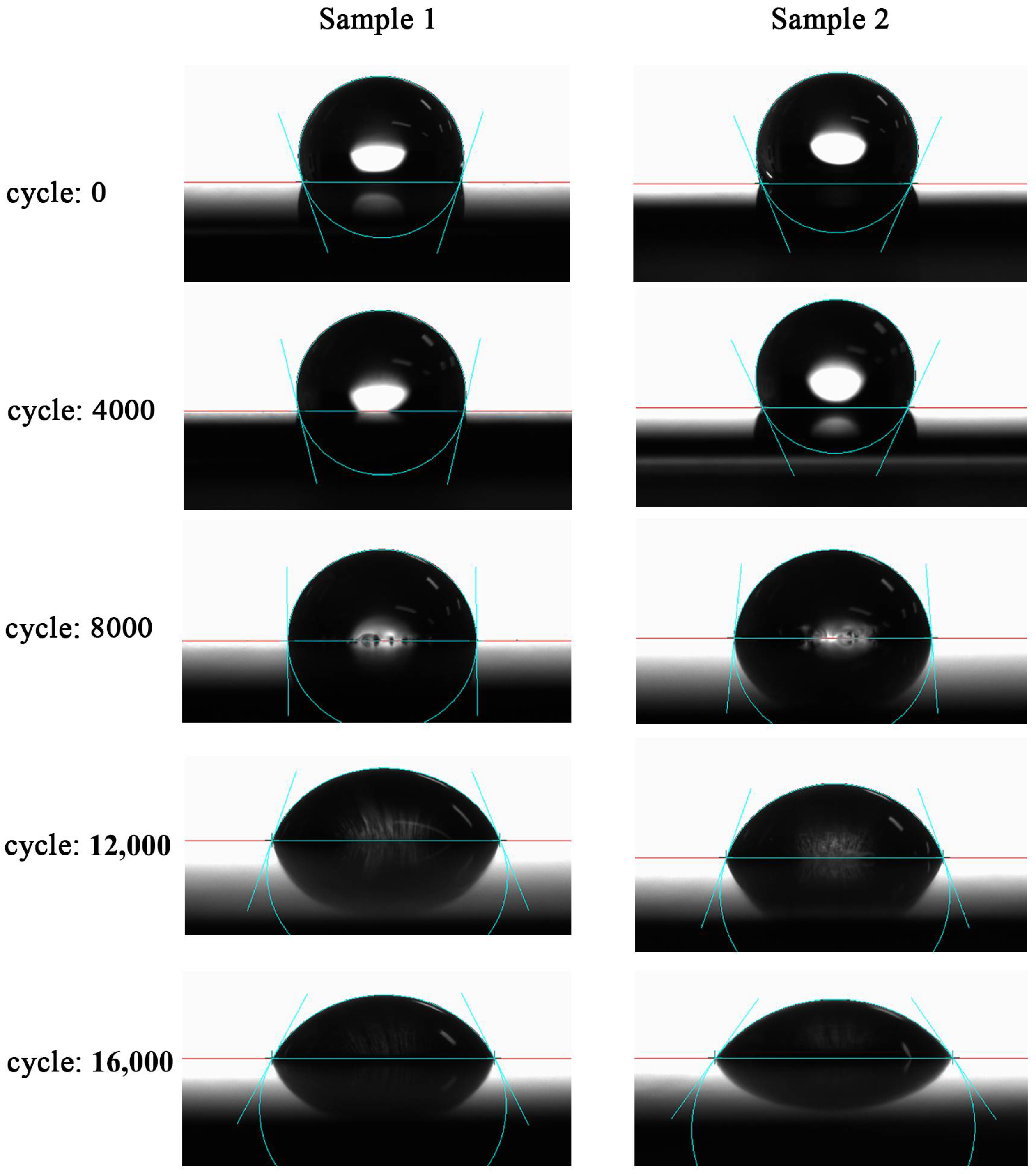
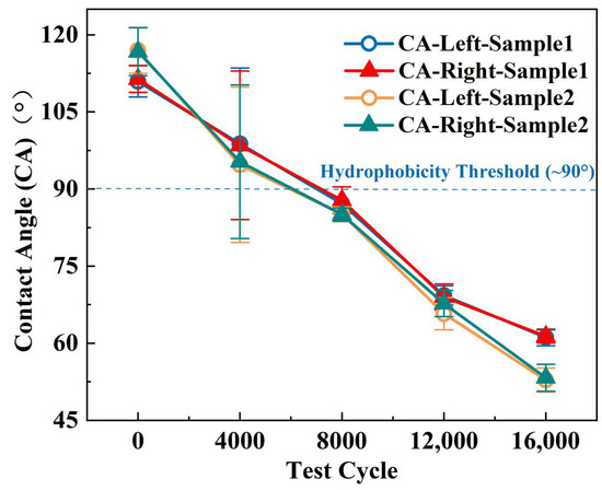
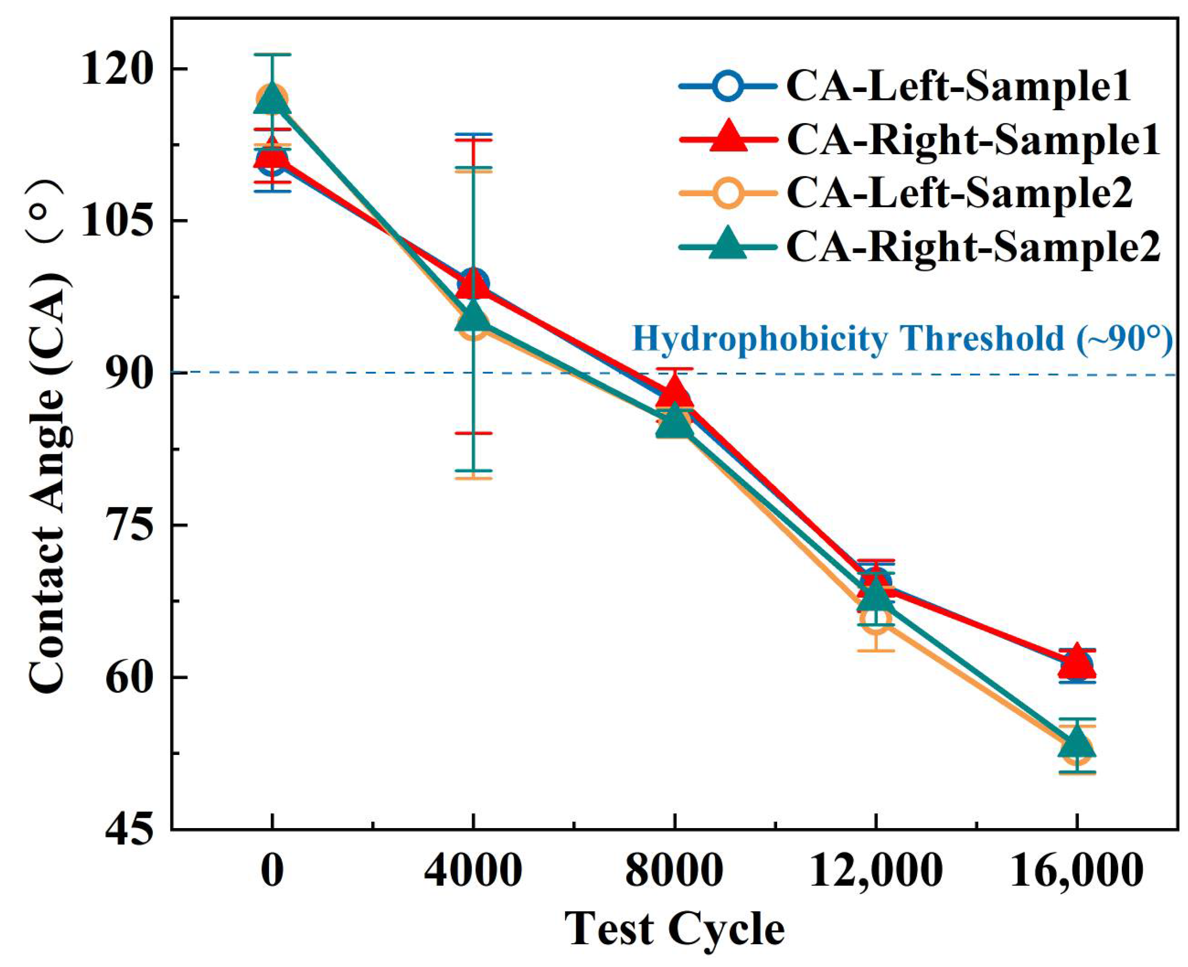
To analyze the effect of thermal cycling on the hydrophobic properties of bipolar plates, the contact angle of graphite bipolar plates was measured after every 4000 cycles. Each sample was tested five times, with the average value adopted for subsequent analysis. The results are shown in Figure 6 and Figure 7. It can be seen that the contact angle variations of both samples exhibited a three-stage pattern with distinct degradation rates. In the initial stage (0–4000 cycles), the left and right contact angles of Sample 1 decreased by 12.2° and 12.9°, respectively, while those of Sample 2 decreased by 22.3° and 21.4°, respectively. In the middle stage (4000–12,000 cycles), the contact angles of Sample 1 and Sample 2 decreased by approximately 29°, indicating a sustained high degradation rate during this stable decay phase as surface damage accumulated progressively. In the late stage (12,000–16,000 cycles), the contact angles of Sample 1 decreased by approximately 8°, and those of Sample 2 decreased by approximately 13.5°, showing a slowed decline rate, though the anti-aging performance differed between the two samples.
Figure 6.
Representative images of contact angle measurements of two samples under different thermal-shock cycles.
Figure 7.
Contact angle changes in graphite bipolar plates after every 4000 thermal-shock cycles.
The significant changes in surface wettability stem from the synergistic effects of multiple mechanisms. Graphite bipolar plates are predominantly composed of carbon; under thermal shock, thermal stress is induced within the material, which can generate defects in the graphite lattice. This enhances the chemical activity of surface carbon atoms and renders them more susceptible to reactions with oxygen or water molecules in the ambient environment, leading to the formation of additional oxygen-containing functional groups (e.g., carboxyl, hydroxyl, and carbonyl groups) on the surface [26]. These hydrophilic functional groups significantly increase the surface energy, facilitating the spreading of water droplets and thus reducing the contact angle.
Furthermore, while graphite materials exhibit high-temperature resistance, repeated severe thermal shocks can lead to localized slight spalling, erosion, or surface microcracks. If the bipolar plate surface originally featured hydrophobicity-enhancing microstructures, such physical damage modifies the surface roughness and morphology. For instance, specific micro-nanostructures that initially supported a contact angle of 110° may be damaged by thermal shock, affecting the solid–liquid interface interaction and transitioning the wetting state to a homogeneous contact where the liquid fully wets the surface (Wenzel state [27]), leading to a significant decrease in the contact angle.
3.4. Effect of Thermal Shock on Roughness
Surface roughness is a critical parameter in the design and manufacturing of bipolar plates. Higher surface roughness reduces the effective actual contact area, leading to increased contact resistance—one of the primary sources of ohmic losses in fuel cells. Furthermore, rough surfaces exhibit a larger specific surface area and more micro-defects (such as peaks and valleys), which are prone to becoming initiation sites for corrosion. The rough surface structure also affects the flow and distribution of liquid water, as well as mechanical assembly and sealing [28].
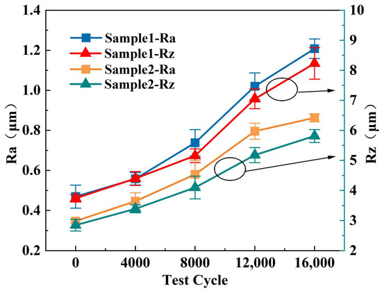
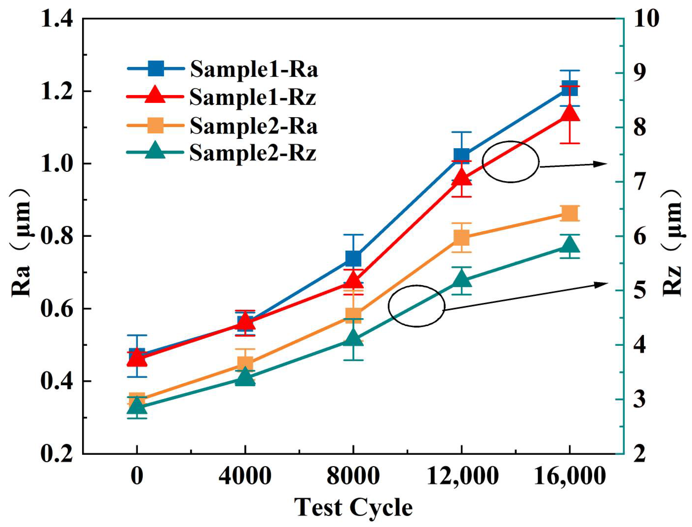
Figure 8 illustrates the changes in surface roughness of the bipolar plates after every 4000 thermal cycles. The arithmetic mean deviation of the profile (Ra) reflects the overall roughness of the sample surface, while the maximum height of the profile (Rz) indicates extreme surface fluctuations. Both samples exhibited an increasing trend in surface roughness. In the first stage (0–4000 cycles), the Ra and Rz of Sample 1 increased by 18.9% and 17.7%, respectively, while those of Sample 2 increased by 28.5% and 19.1%, indicating that surface damage at this stage was primarily characterized by the formation of micro-defects. In the second stage (4000–12,000 cycles), the increases in Ra and Rz for Sample 1 reached 82.9% and 60.2%, respectively, and for Sample 2, 78.3% and 52.6%, indicating accelerated accumulation of surface damage. In the third stage (12,000–16,000 cycles), the increases in Ra and Rz for Sample 1 were 18.4% and 16.8%, respectively, and for Sample 2, 8.5% and 12.2%, indicating a slowed growth rate. Similarly, the increase in surface roughness primarily stems from the synergistic effects of multiple physicochemical mechanisms during thermal cycling. Cyclic thermal stress loading leading to material fatigue damage is the main cause. Additionally, surface oxidation and corrosion processes exacerbate the increase in roughness. The continuous increase in surface roughness, manifested by the rising Ra and Rz values, is the direct topographic consequence of the physical and chemical degradation mechanisms described in Section 3.1 and Section 3.2. Specifically, the propagation of thermal stress-induced microcracks, coupled with the formation and spallation of oxide layers at defect sites, synergistically disrupts the original surface morphology, leading to its increased irregularity.
Figure 8.
Surface roughness changes in graphite bipolar plates under thermal shock cycles.
3.5. Effect of Thermal Shock on Corrosion Current Density
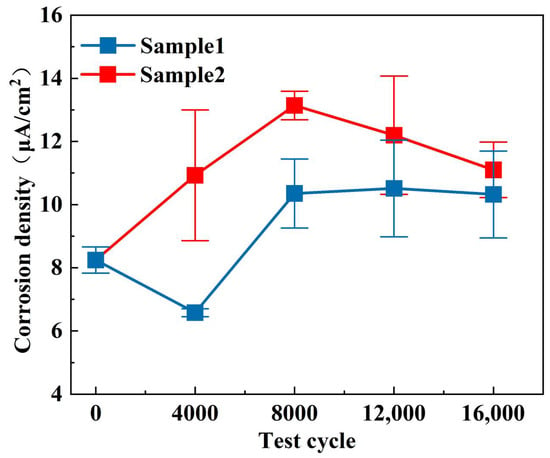
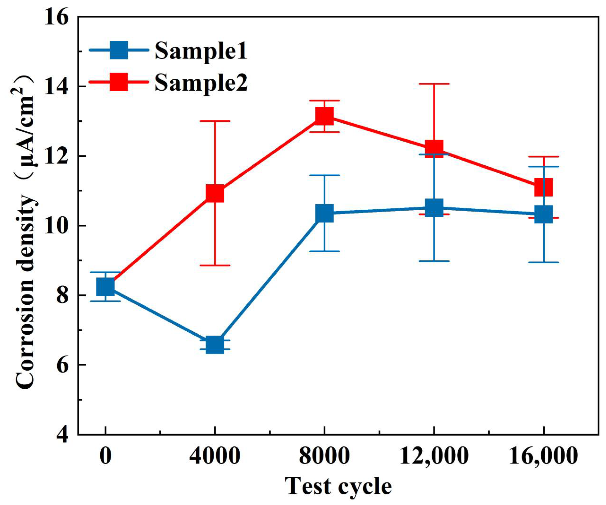
This study also monitored the changes in corrosion current density of the graphite bipolar plates, as shown in Figure 9. It was found that the corrosion current density did not increase significantly even after 16,000 thermal shock cycles, and even showed a slight decreasing trend in the later stages. This phenomenon indicates that the damage induced by thermal shock is predominantly physical, manifested as microcracks, interfacial debonding, and spalling caused by the mismatch in the coefficients of thermal expansion between the resin and graphite particles. Such damage does not substantially alter the inherent chemical inertness of the graphite substrate. Furthermore, EDS analysis revealed an increase in oxygen content on the surface, particularly along the crack edges. These oxidation products, covering the graphite surface, may form an extremely thin yet dense oxide layer that acts as a barrier, preventing further contact and reaction between the aqueous medium and the internal graphite material, thereby suppressing increase in corrosion current. In addition, the layered structure and high bond energy of graphite make it extremely chemically inert. Even under physical damage induced by thermal shock, the matrix does not undergo obvious electrochemical corrosion, and only the barrier effect of surface oxidation products dominates the change in corrosion current. Consequently, the absence of a significant rise in corrosion current density underscores that the core mechanism of aging in graphite bipolar plates is their susceptibility to physical fatigue damage rather than electrochemical corrosion. Thus, efforts should focus on enhancing their thermal shock resistance—such as by optimizing the interfacial bonding between resin and graphite, reducing porosity, and utilizing composite materials with matched coefficients of thermal expansion—rather than concentrating solely on improving chemical corrosion resistance.
Figure 9.
Changes in potentiostatic corrosion current density of graphite bipolar plates under thermal cycles.
4. Conclusions
Through systematic accelerated thermal cycling tests, this study thoroughly investigated the aging behavior and performance degradation mechanisms of graphite bipolar plates under dynamic temperature environments. The research revealed that with increasing numbers of thermal cycles, the initial banded microcracks and crack holes on the bipolar plate surface progressively expanded. EDS analysis demonstrated significant oxygen enrichment at crack edges, indicating continuously intensifying surface oxidation. The combined effects of microcrack propagation and surface oxide layer formation led to decreased electrical conductivity. The generation of oxygen-containing functional groups and destruction of surface microstructures resulted in markedly reduced hydrophobicity. The synergistic action of thermal fatigue and oxidative corrosion exacerbated surface morphology inhomogeneity, causing substantial increases in surface roughness. The corrosion current density showed no significant increase throughout the testing process, indicating that material aging is primarily dominated by physical fatigue damage, while the graphite substrate itself maintained high chemical stability.
Therefore, the performance degradation of graphite bipolar plates under alternating temperature conditions results from the combined effects of physical damage and surface oxidation. To enhance their durability under dynamic operating conditions, material design, interface strengthening, and protection strategies should prioritize improving thermal shock resistance through methods such as optimizing resin-graphite interfacial bonding, reducing material porosity, and developing composite material systems with matched coefficients of thermal expansion.
Author Contributions
Conceptualization, D.J., Y.H. and D.H.; methodology, D.J. and F.L.; software, D.J. and F.L.; formal analysis, D.J. and F.L.; investigation, D.J., F.L. and R.W.; resources, D.H.; data curation, D.J., F.L. and R.W.; writing—original draft preparation, D.J. and F.L.; writing—review and editing, Y.H. and D.H.; visualization, D.J. and F.L.; supervision, Y.H. and D.H.; project administration, Y.H. and D.H.; funding acquisition, Y.H. All authors have read and agreed to the published version of the manuscript.
Funding
This study was supported by the National Key R&D Program of China, No. 2023YFE0109200.
Data Availability Statement
The data presented in this study are available on request from the corresponding author. The data of the paper has been made publicly available to a sufficient extent. For access to more and the raw data, please contact the corresponding author due to privacy considerations.
Conflicts of Interest
Authors Daokuan Jiao, Ruidi Wang and Dong Hao were employed by the company China Automotive Technology and Research Center Co., Ltd. and CATARC New Energy Vehicle Research and Inspection Center (Tianjin) Co., Ltd. The remaining authors declare that the research was conducted in the absence of any commercial or financial relationships that could be construed as a potential conflict of interest.
References
- Dincer, I. Renewable energy and sustainable development: A crucial review. Renew. Sustain. Energy Rev. 2000, 4, 157–175. [Google Scholar] [CrossRef] [Scilit]
- Ferruzzi, G.; Delcea, C.; Barberi, A. Concentrating solar power: The state of the art, research gaps and future perspectives. Energies 2023, 16, 8082. [Google Scholar] [CrossRef] [Scilit]
- Wang, J.; Wen, J.; Wang, J.; Yang, B.; Jiang, L. Water electrolyzer operation scheduling for green hydrogen production: A review. Renew. Sustain. Energy Rev. 2024, 203, 114779. [Google Scholar] [CrossRef] [Scilit]
- Song, Q.; Yang, S.; Li, H.; Ji, Y.; Cai, D.; Wang, G.; Liufu, Y. Performance Improvement of Proton Exchange Membrane Fuel Cell by a New Coupling Channel in Bipolar Plate. Energies 2025, 18, 4068. [Google Scholar] [CrossRef] [Scilit]
- Xu, Y.; Zhang, G.; Wu, L.; Bao, Z.; Zu, B.; Jiao, K. A 3-D multiphase model of proton exchange membrane electrolyzer based on open-source CFD. Digit. Chem. Eng. 2021, 1, 100004. [Google Scholar] [CrossRef] [Scilit]
- Kim, T.; Nguyen, N.D.; Kim, Y.; Yu, S. Experimental investigation of time-dependent electrical load effects through multipoints in-situ measurement of temperature and relative humidity of PEMFC bipolar plate under transient operation. Appl. Therm. Eng. 2024, 247, 123049. [Google Scholar] [CrossRef] [Scilit]
- Luo, M.; Zhang, J.; Zhang, C.; Chin, C.S.; Ran, H.; Fan, M.; Du, K.; Shuai, Q. Cold start investigation of fuel cell vehicles with coolant preheating strategy. Appl. Therm. Eng. 2022, 201, 117816. [Google Scholar] [CrossRef] [Scilit]
- Choe, J.; Lim, J.W.; Kim, M.; Kim, J.; Lee, D.G. Durability of graphite coated carbon composite bipolar plates for vanadium redox flow batteries. Compos. Struct. 2015, 134, 106–113. [Google Scholar] [CrossRef] [Scilit]
- Song, Y.; Zhang, C.; Ling, C.Y.; Han, M.; Yong, R.-Y.; Sun, D.; Chen, J. Review on current research of materials, fabrication and application for bipolar plate in proton exchange membrane fuel cell. Int. J. Hydrogen Energy 2020, 45, 29832–29847. [Google Scholar] [CrossRef] [Scilit]
- Windarto, C.; Chanda, U.K.; Lim, O. A review of materials and surface processing for bipolar plates in polymer electrolyte membrane fuel cells. Int. J. Hydrogen Energy 2024, 92, 419–433. [Google Scholar] [CrossRef] [Scilit]
- Liu, J.; Zhang, L.; Yuan, B.; Zhang, Y.; Yang, Z.; Huang, J. Design and development of coating for metallic bipolar plates in proton exchange membrane fuel cell (PEMFC): A review. Mater. Des. 2024, 246, 113338. [Google Scholar] [CrossRef] [Scilit]
- Zhao, T.; Islam, M.A.; He, X.; Saha, B.B. Application of metallic bipolar plates in PEMFCs: A comprehensive review of performance and durability. Renew. Sustain. Energy Rev. 2026, 226, 116421. [Google Scholar] [CrossRef] [Scilit]
- Suhas, R.; Vishwas, V.G.; Bharatish, A. A Comprehensive Review on Performance Metrics of Surface Coated Bipolar Plates of PEMFC. Next Res. 2025, 2, 100795. [Google Scholar] [CrossRef] [Scilit]
- McCay, K.; Prokop, M.; Alsos, Ø.; Reksten, A.H.; Hala, M.; Ludvík, J.; Thind, N.; Raux, M.-A.; Denonville, C.; Torkzad, F.; et al. An innovative filler manipulation approach for low-cost composite coatings on metallic PEMFC bipolar plates. Fuel 2026, 405, 136686. [Google Scholar] [CrossRef] [Scilit]
- Feng, K.; Cai, X.; Sun, H.; Li, Z.; Chu, P.K. Carbon coated stainless steel bipolar plates in polymer electrolyte membrane fuel cells. Diam. Relat. Mater. 2010, 19, 1354–1361. [Google Scholar] [CrossRef] [Scilit]
- Asri, N.F.; Husaini, T.; Sulong, A.B.; Majlan, E.H.; Daud, W.R.W. Coating of stainless steel and titanium bipolar plates for anticorrosion in PEMFC: A review. Int. J. Hydrogen Energy 2017, 42, 9135–9148. [Google Scholar] [CrossRef] [Scilit]
- Roncaglia, F.; Mucci, A.; Romagnoli, M.; Spinelli, L.; di Bona, A.; Biagi, R. Graphite-epoxy composites for bipolar plates: The gas permeability issue. Int. J. Hydrogen Energy 2023, 48, 20935–20944. [Google Scholar] [CrossRef] [Scilit]
- Sun, X.; Yang, L.; Shi, L.; Qi, P.; Jiang, M.; Wang, J.; Xiong, Y.; Su, Y. Carbon thermal shock assisted activated carbon for lead carbon batteries: Uniform loading of lead nanoparticles and pore regulation. J. Energy Storage 2023, 73, 108992. [Google Scholar] [CrossRef] [Scilit]
- Latella, B.A.; Liu, T. The initiation and propagation of thermal shock cracks in graphite. Carbon 2006, 44, 3043–3048. [Google Scholar] [CrossRef] [Scilit]
- Fu, Y.; Zhang, Y.; Li, T.; Zhang, J.; Han, L.; Wang, P.; Shen, Q.; Wang, X.; Eckert, J. Thermal shock resistance of carbon-based composites reinforced by HfC nanowires under extreme conditions. Ceram. Int. 2024, 50, 35287–35297. [Google Scholar] [CrossRef] [Scilit]
- Chen, Y.; Ding, J.; Deng, C.; Yu, C. Improved thermal shock stability and oxidation resistance of low-carbon MgO–C refractories with introduction of SiC whiskers. Ceram. Int. 2023, 49, 26871–26878. [Google Scholar] [CrossRef] [Scilit]
- Luo, Y.; Wang, X.; Liu, Z.; Yu, C.; Deng, C.; Ding, J. Enhanced oxidation resistance and thermal shock resistance of low-carbon Al2O3–C refractories with nano-BN: A synergistic of mullitization behavior. J. Alloys Compd. 2024, 975, 172937. [Google Scholar] [CrossRef] [Scilit]
- Wei, W.; Song, Y.; Yang, Z.; Gao, G.; Xu, P.; Lu, M.; Tu, C.; Chen, M.; Wu, G. Investigation of the impacts of thermal shock on carbon composite materials. Materials 2019, 12, 435. [Google Scholar] [CrossRef] [Scilit]
- Ural, N. The significance of scanning electron microscopy (SEM) analysis on the microstructure of improved clay: An overview. Open Geosci. 2021, 13, 197–218. [Google Scholar] [CrossRef] [Scilit]
- Girão, A.V.; Caputo, G.; Ferro, M.C. Application of scanning electron microscopy–energy dispersive X-ray spectroscopy (SEM-EDS). In Comprehensive Analytical Chemistry; Elsevier: Amsterdam, The Netherlands, 2017; Volume 75, pp. 153–168. [Google Scholar]
- Lu, Y.; Li, E.; Cheng, H.; Wang, X.; Du, Z.; Cheng, F.; Miller, J.D. Effect of oxygen functional groups on the surface properties and flotation response of fine coal, comparison of rank with oxidation. Int. J. Coal Prep. Util. 2021, 41, 290–306. [Google Scholar] [CrossRef] [Scilit]
- Wenzel, R.N. Surface roughness and contact angle. J. Phys. Chem. 1949, 53, 1466–1467. [Google Scholar] [CrossRef] [Scilit]
- Bao, Y.; Gan, Y. Roughness effects of gas diffusion layers on droplet dynamics in PEMFC flow channels. Int. J. Hydrogen Energy 2020, 45, 17869–17881. [Google Scholar] [CrossRef] [Scilit]
Disclaimer/Publisher’s Note: The statements, opinions and data contained in all publications are solely those of the individual author(s) and contributor(s) and not of MDPI and/or the editor(s). MDPI and/or the editor(s) disclaim responsibility for any injury to people or property resulting from any ideas, methods, instructions or products referred to in the content. |
© 2026 by the authors. Licensee MDPI, Basel, Switzerland. This article is an open access article distributed under the terms and conditions of the Creative Commons Attribution (CC BY) license.