


Abstract
A unified power quality conditioner (UPQC) is developed for the mitigation of grid-voltage and -current distortions under steady-state and dynamic conditions. The proposed configuration integrates series and shunt inverters through a common DC-link capacitor. The capacitor functions as an energy buffer by accommodating the power exchanged between the two inverters. Following an abrupt grid-voltage disturbance or load transition, the DC-link capacitor must instantaneously deliver or absorb power to maintain the power balance between the inverters while sustaining the required compensation. The resulting transient energy exchange can produce pronounced DC-link voltage excursions, with adverse consequences for system stability and compensation accuracy. Rapid and accurate regulation of the DC-link voltage is therefore essential for maintaining the dynamic compensation performance of the UPQC. To improve this regulation, a compensatory wavelet fuzzy neural network incorporating asymmetric membership functions (CWFNN-AMFs) is introduced in place of the conventional proportional–integral (PI) controller. The network architecture and its online learning algorithm are derived in detail. Finally, experimental results under steady-state and dynamic conditions demonstrate that the CWFNN-AMF-controlled UPQC improves both power quality compensation and DC-link voltage regulation, thereby verifying the feasibility and effectiveness of the proposed control framework.
1. Introduction
Growing concerns regarding global warming, greenhouse-gas emissions, and energy security have accelerated the integration of renewable energy-based distributed generation (DG), particularly wind generation (WG) and photovoltaic generation (PV), into utility grids [1]. Meanwhile, critical and disturbance-sensitive loads, including X-ray systems, electric arc furnaces, adjustable speed drives, switched-mode power supplies, and communication systems, are increasingly employed in medical, commercial, and industrial facilities [2]. These developments, together with switching transients, abrupt load changes, and phase unbalance [3], have intensified concerns regarding grid power quality [4]. Renewable source intermittency, unpredictable load variations, and power electronic interfaces may cause excessive reactive power demand, harmonic and unbalanced currents, voltage sags and swells, and voltage unbalance [5]. Such disturbances can result in equipment malfunction, process interruption, or shutdown, particularly in sensitive manufacturing processes such as semiconductor fabrication [6]. Effective power quality compensation is therefore essential for ensuring the reliable operation of modern distribution systems.
Among the available compensation technologies, the unified power quality conditioner (UPQC) provides coordinated mitigation of supply voltage disturbances and load current distortions. A UPQC combines series and shunt active power filters (APFs), interconnected by a common DC-link capacitor that supports the requisite power exchange between the inverters. This topology enables simultaneous compensation of current harmonics, phase current unbalance, voltage sags, and power factor (PF) degradation. UPQC control is commonly formulated using either instantaneous reactive power (IRP) theory or the synchronous reference frame (SRF) method [7,8,9]. Under IRP-based control, the shunt-inverter reference is obtained from the instantaneous power evaluated in a stationary reference frame, whereas the series inverter is governed by a directly generated voltage command [10]. Although this formulation yields a comparatively simple control structure, its accuracy can be affected under distorted or unbalanced conditions. The SRF method, by contrast, regulates both inverters in a synchronously rotating reference frame and consequently requires reliable phase-locked loop synchronization. Because voltage distortion can directly impair phase estimation, synchronization constitutes a critical element of the SRF implementation. Despite its greater computational complexity, the SRF method generally offers superior control accuracy and has consequently been adopted extensively in UPQC systems [11]. Thus, many control strategies have been reported to improve UPQC performance [12,13,14]. An adaptive controller was applied to a photovoltaic integrated UPQC in [12], whereas a direct adaptive strategy based on a command-generator tracker was developed for UPQC in [13]. Nonlinear sliding-mode control and switching dynamic control were employed for the DC-link voltage regulation of UPQC [14]. In addition, because the series and shunt inverters exchange energy through their common capacitor, grid-voltage disturbances and sudden load change cause instantaneous power to flow into or out of the DC-link capacitor in the UPQC [15,16]. The resulting DC-link voltage fluctuations directly affect the transient compensation response. Consequently, rapid and accurate DC-link voltage regulation is essential to UPQC operation.
Conventional proportional–integral (PI) controllers exhibit limited adaptability to operating point variations and external disturbances because their gains remain fixed. Moreover, fuzzy neural networks (FNNs) have been investigated as nonlinear alternatives; however, their fixed fuzzy operators restrict inference optimization and provide limited degrees of freedom [17]. The compensatory fuzzy neural network (CFNN) augments an FNN with an adaptive compensatory mechanism, permitting online adjustment of the membership functions and fuzzy operators [18,19]. Through pessimistic, optimistic, and compensatory neurons, the CFNN determines an appropriate response between limiting decision conditions [20]. CFNN-based controllers with asymmetric membership functions (AMFs) were applied to unbalanced-current compensation in a photovoltaic system [19] and to power-quality improvement and DC-link voltage regulation in a distribution static synchronous compensator (DSTATCOM) [20]. The wavelet fuzzy neural network (WFNN), formed by integrating a wavelet neural network with an FNN, exploits the multiresolution and localization properties of wavelet functions. These properties enable accurate nonlinear approximation using a compact network structure while supporting rapid convergence and parallel computation [21,22]. WFNN-based controllers have been investigated in various electromechanical systems. A Petri-WFNN controller was applied to a squirrel-cage induction generator system to smooth the wind-power output [23], whereas a WFNN-based second-order sliding-mode controller was employed in an electric power-assisted steering system to improve steering accuracy [24]. Nevertheless, conventional FNNs generally employ symmetric Gaussian membership functions. Although these functions facilitate analytical formulation, their limited geometric flexibility may require numerous fuzzy rules to achieve adequate approximation accuracy. By extending the Gaussian membership function to an asymmetric form, an AMF provides greater representational flexibility, thereby reducing the number of fuzzy rules required and enhancing network learning [25]. Recent intelligent control methods have also been investigated for UPQC applications. A neural network-based admittance estimation strategy was employed in [26] to estimate fundamental admittance components and generate compensation references under distorted and unbalanced operating conditions. An artificial neural network (ANN) controller was applied to a microgrid-integrated UPQC in [27] for reference-signal generation and DC-link voltage regulation. In [28], an adaptive neuro-fuzzy inference system (ANFIS) was developed as the DC-link voltage controller for a customized UPQC. In [29], an adaptive dynamic neural network was combined with an optimized PI controller for disturbance estimation and DC-link voltage regulation. These studies demonstrate the effectiveness of neural and neuro-fuzzy techniques in improving UPQC performance. However, the intelligent components in these representative studies are primarily employed for admittance or disturbance estimation, reference-signal generation, ANN or ANFIS control, or PI-gain optimization. They do not jointly incorporate wavelet-based localized approximation, adaptive compensatory inference, asymmetric fuzzy partitioning, and coordinated online parameter adaptation within a single UPQC DC-link voltage controller. Beyond neural network-based control, recent UPQC studies have also investigated model-predictive, sliding-mode, and disturbance observer-based approaches. A continuous-control-set model predictive control strategy was developed for a modular multilevel converter (MMC)-based UPQC under non-ideal operating conditions [30]. A passivity fractional-order sliding-mode controller was proposed to improve the dynamic performance and robustness of the UPQC [31]. In addition, a nonlinear disturbance observer-based UPQC with battery energy storage was developed to provide disturbance estimation and feedforward compensation for DC-bus voltage regulation [32]. Although these advanced approaches provide rapid dynamic response and enhanced disturbance rejection, their implementation generally involves an explicit system model, online optimization, carefully designed control or observer parameters, or an auxiliary energy-storage configuration. Accordingly, this study develops a six-layer compensatory wavelet fuzzy neural network with asymmetric membership functions (CWFNN-AMF) for UPQC DC-link voltage regulation. The proposed architecture combines the fuzzy-rule and wavelet outputs in an adaptive compensation layer, while its compensatory, wavelet, and asymmetric-membership parameters are jointly adjusted online using the DC-link voltage tracking error. The corresponding online learning laws and convergence conditions are derived for the integrated network. The CWFNN-AMF replaces the conventional PI and FNN controllers to improve the dynamic regulation of the UPQC under grid-voltage disturbances and load variations.
In this study, the SRF method is adopted in the developed UPQC owing to its merits, whereas the CWFNN-AMF parameters are trained online to improve DC-link voltage regulation and the compensation of current and voltage distortions. Under steady-state conditions, the proposed system is evaluated in terms of grid-current balancing, total harmonic distortion (THD), and PF correction. Under dynamic conditions, the transient responses to load variation, voltage sag, and voltage swell are examined. The operating principles and control architecture of the developed UPQC are presented in Section 2. The network structure, online learning laws, and convergence analysis of the proposed CWFNN-AMF are derived in Section 3. Then, in Section 4, the effectiveness of the proposed CWFNN-AMF-controlled UPQC in DC-link voltage regulation and power-quality improvement is verified experimentally. Finally, the conclusions are summarized in Section 5.
2. Operating Principles of the UPQC
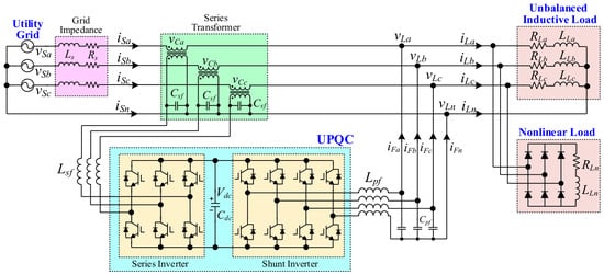
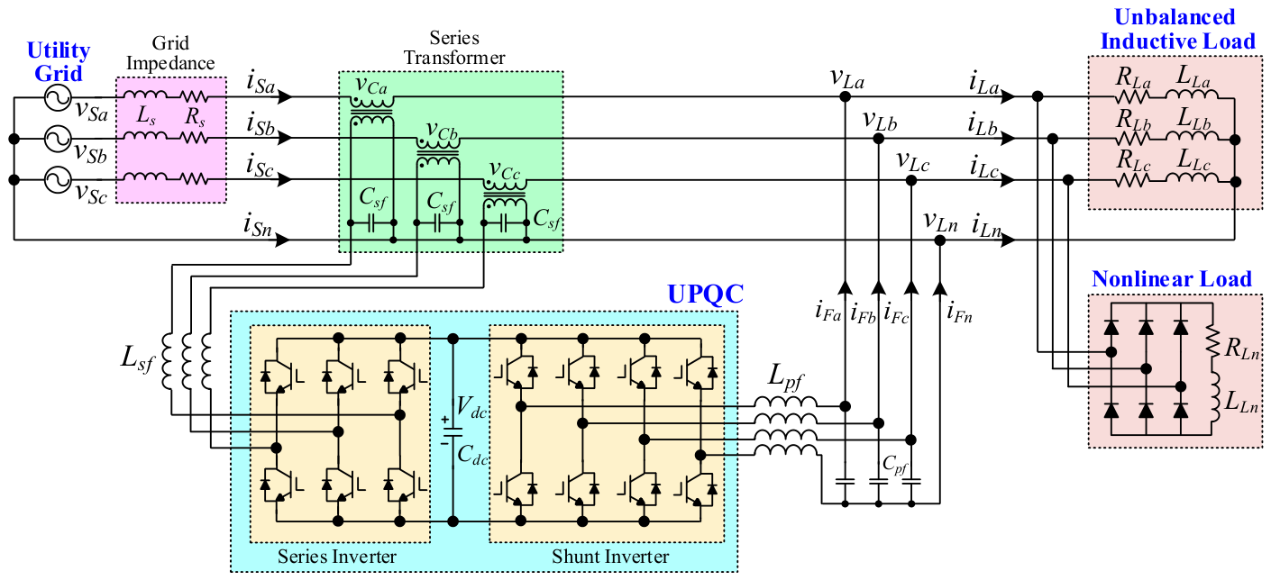
The configuration of the UPQC connected between the utility grid and the load is illustrated in Figure 1. The UPQC comprises a three-phase four-leg shunt inverter on the load side and a three-phase three-leg series inverter on the grid side; both inverters share a common DC-link capacitor for power balancing [33]. The load consists of three-phase nonlinear and unbalanced inductive loads, and the source is a three-phase, four-wire distribution system with a line-to-line voltage of and frequency of . The grid neutral is connected to the fourth shunt inverter leg and the load neutral, thereby suppressing the grid-current unbalance attributable to load asymmetry.
Figure 1.
Configuration of right-shunt UPQC with power grid and load.
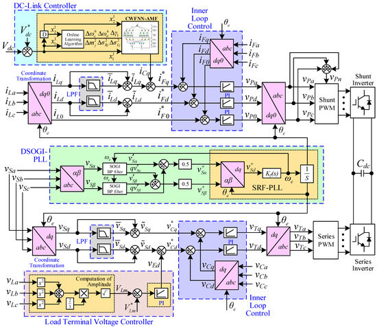
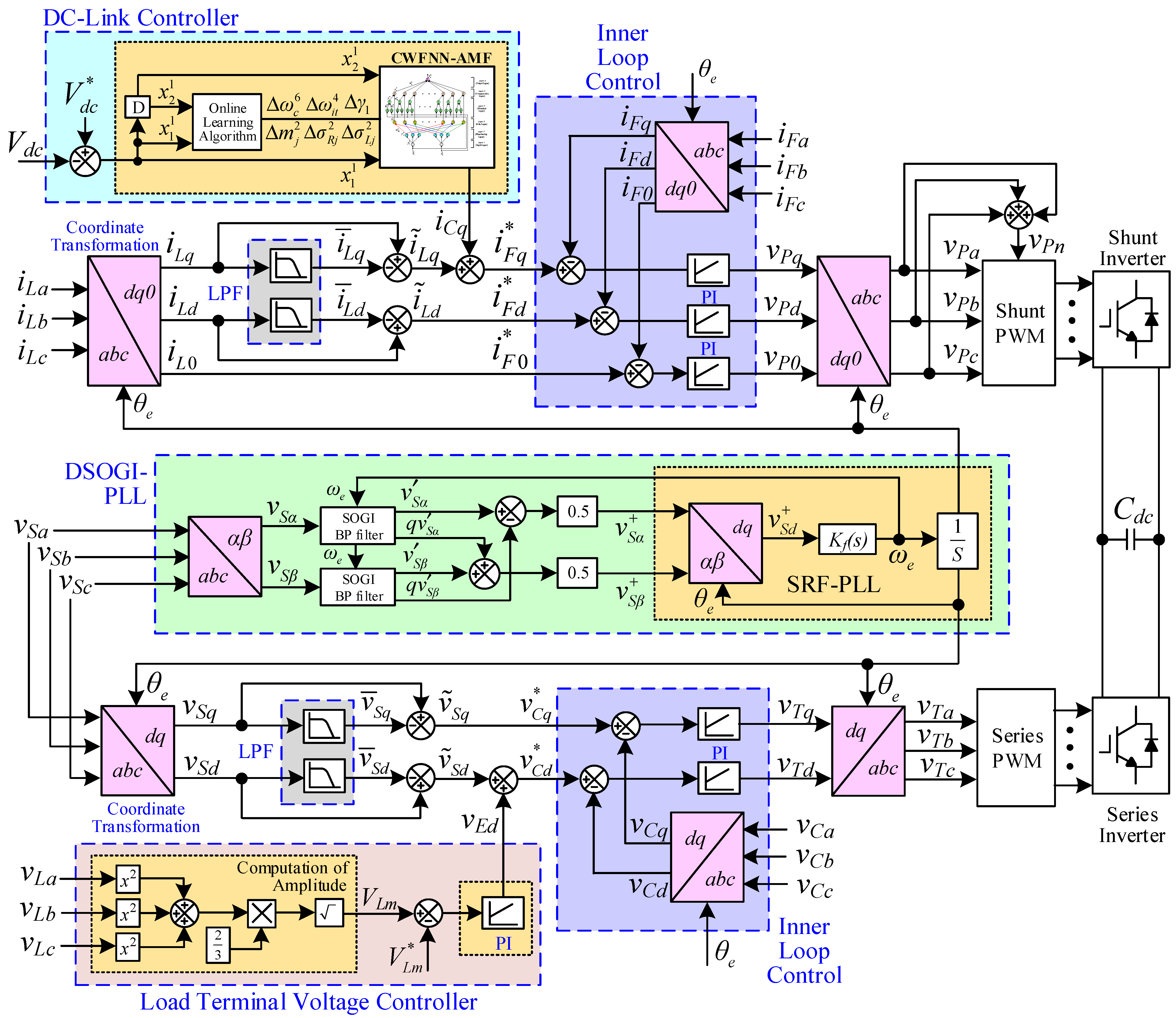
The block diagram of the UPQC incorporating the proposed CWFNN-AMF controller is presented in Figure 2. A dual second-order generalized integrator phase-locked loop (DSOGI-PLL) provides the phase angle required for synchronous reference frame transformations. The shunt inverter control regulates the DC-link voltage and compensates load current distortion, whereas the series inverter control mitigates supply voltage disturbances and regulates the load-voltage magnitude.
Figure 2.
Block diagram of UPQC using the proposed CWFNN-AMF.
Accurate grid-angle synchronization is required under grid-voltage disturbances. A single-phase voltage sag or swell produces three-phase voltage unbalance and may introduce negative-sequence components, resulting in angle-estimation errors in a conventional synchronous reference frame phase-locked loop (SRF-PLL). To address this limitation, the DSOGI-PLL is employed to extract the positive-sequence voltage component. The measured grid voltages, , are processed through the transformation, DSOGI filtering, positive-sequence extraction, and SRF-PLL control to obtain the grid phase angle, [34].
For shunt-inverter control, the measured three-phase load currents, , are first transformed into the synchronous reference frame:
Second-order low-pass filters (LPFs) are employed to extract the DC components, , from the d- and q-axis load currents, and , respectively. The corresponding AC components, , which constitute the current compensation terms, are obtained by subtracting the DC components from the respective d- and q-axis load currents. The measured DC-link voltage, , is then compared with its reference, and the resulting error is processed by the DC-link voltage controller to generate the q-axis control signal, . On the synchronous q-axis, the AC component of the load current is added to the q-axis control signal to form the q-axis current command, . The AC component of the load d-axis current forms the d-axis current command, , whereas the load zero-axis current forms the zero-axis current command, . The measured shunt-inverter output currents, , are likewise transformed into the synchronous reference frame and compared with the corresponding current commands. The resulting errors are processed by PI controllers to obtain the shunt-inverter voltage control commands, . Finally, these commands are transformed back into the three-phase stationary reference frame, yielding the three-phase voltage commands, .
The fourth-leg voltage command, , is obtained from the three-phase voltage commands as follows:
The fourth leg provides a controlled path for zero-sequence and neutral currents. As shown in Figure 2, the load zero-axis current is used to generate the zero-axis current command, , and the corresponding current-tracking error is processed to obtain the zero-axis voltage command, . Following the inverse transformation, is incorporated into the three-phase voltage commands used to generate . The fourth-leg controller suppresses the grid neutral current and zero-sequence unbalance and indirectly affects the DC-link transient response through the instantaneous power exchanged during compensation. The four-leg voltage references are supplied to the pulse width modulation (PWM) stage to synthesize the shunt-inverter switching signals. The resulting inverter current mitigates grid-current distortion while maintaining the prescribed DC-link voltage of the UPQC.
For series inverter control, the measured three-phase grid voltages are first transformed into the synchronous reference frame. The DC components, , of the synchronous axis grid voltages are extracted using LPFs. Subtracting these DC components from the corresponding synchronous axis voltages yields their AC components, . In addition, the magnitude of the measured three-phase load voltage is calculated as follows:
The three-phase load-voltage magnitude is compared with its reference, and the resulting error is processed by a PI controller to obtain the d-axis voltage control signal, . On the d-axis, the AC component of the grid voltage is added to this control signal to form the d-axis voltage command, ; on the q-axis, the AC component of the grid-voltage directly forms the q-axis voltage command, . The measured series inverter output voltages, , are also transformed into the synchronous reference frame and compared with the corresponding voltage commands. The resulting errors are processed by inner-loop PI controllers to obtain the series inverter voltage control commands, . Finally, these commands are transformed back into the three-phase stationary reference frame to obtain the three-leg voltage commands, . The resulting voltage references are supplied to the PWM stage to synthesize the series inverter switching signals, through which disturbances in the grid voltage are compensated.
3. Intelligent CWFNN-AMF Controller
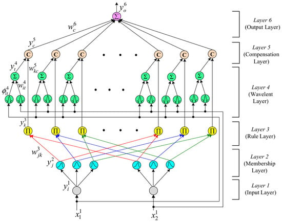
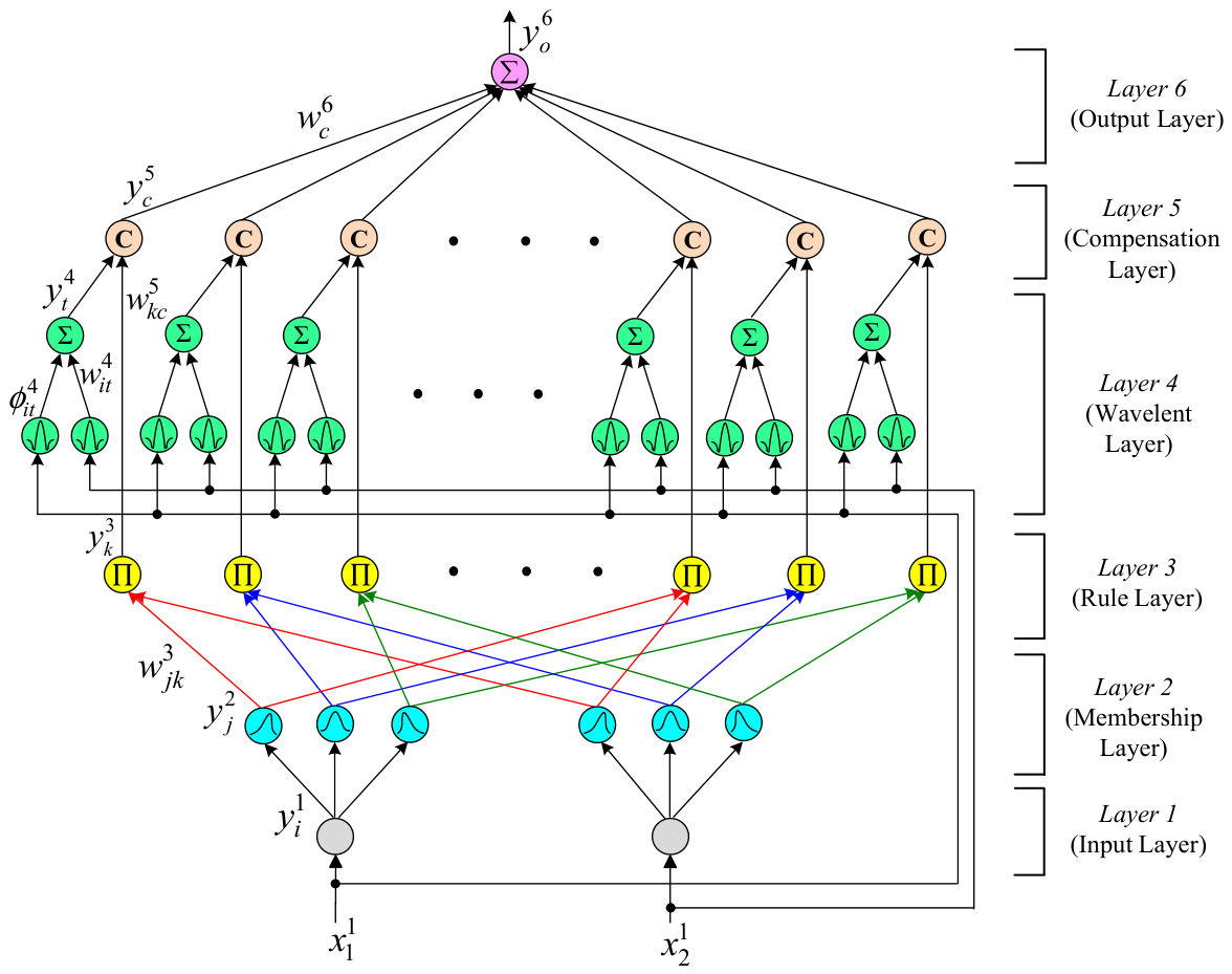
Despite their implementation simplicity, PI controllers provide limited robustness when fixed gains are applied over a wide operating range. Grid-voltage disturbances and load transitions alter the instantaneous power exchanged through the DC-link capacitor of the UPQC and can therefore produce substantial voltage deviations [15,16]. These deviations directly affect inverter modulation and compensation accuracy. To improve regulation under such time-varying conditions, the CWFNN-AMF is proposed to replace the conventional PI and FNN controllers for the DC-link voltage regulation. The network structure of the proposed CWFNN-AMF controller is illustrated in Figure 3. The formulation of its six constituent layers and the corresponding online learning laws is presented in the following.
Figure 3.
Network structure of the CWFNN-AMF controller.
3.1. Network Structure
- Input Layer:
The input nodes directly transmit the input signals to the subsequent layer. The operation of each node is defined as follows:
The inputs to the proposed CWFNN-AMF are the DC-link voltage error and its time derivative. N denotes the iteration index.
- 2.
- Membership Function Layer:
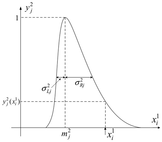
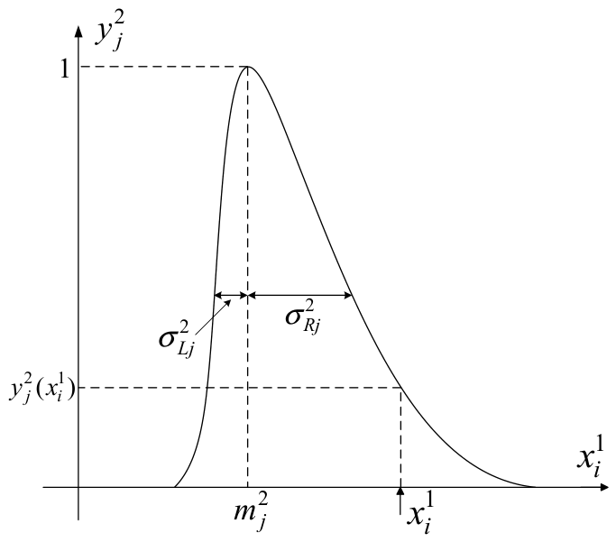
As illustrated in Figure 4, asymmetric Gaussian membership functions are employed for fuzzification in this layer, thereby improving function approximation accuracy. The corresponding functions are defined as follows:
where , , and denote the center, left standard deviation, and right standard deviation of the asymmetric Gaussian membership function, respectively.
Figure 4.
Asymmetric Gaussian function in membership layer of the CWFNN-AMF controller.
- 3.
- Rule Layer:
Each node performs a multiplicative aggregation in accordance with the prescribed network rules, and the resulting node output is defined as follows:
where denotes the connection weight between the membership and rule layers and is fixed at unity.
- 4.
- Wavelet Layer:
The wavelet functions are defined as follows:
where and depict the translation and dilation coefficients of the wavelet function, respectively, and denotes the connection weight applied to the corresponding wavelet output.
- 5.
- Compensation Layer:
This layer comprises two computational components. First, the outputs of the fourth and third layers are multiplied to perform fuzzy rule inference. Second, the resulting inference value is processed using the compensatory parameters to improve network adaptability. The operation of this layer is therefore defined as follows:
where expresses the aggregated input to the cth node in the fifth layer, corresponding to the fuzzy-inference result; is the connection weight between the wavelet and compensation layers; is the compensation degree; and denotes the number of inputs to the neuron. To improve the adaptive capability of the compensation mechanism while ensuring that remains within [0, 1], the compensation degree is defined as follows [18]:
where and stand for the compensatory operators, the values of which are updated through online training.
- 6.
- Output Layer:
This layer performs defuzzification through the summation operator, , as follows:
where is the connection weight from the compensation layer to the output layer, and is the CWFNN-AMF output, corresponding to the synchronous q-axis control signal, , of the shunt-side DC-link voltage controller, as shown in Figure 2.
3.2. Online Learning Algorithm
The online learning laws of the proposed intelligent network are derived using backpropagation and supervised gradient descent. During online learning, the gradient vector is recursively evaluated, the error function is minimized, and the CWFNN-AMF parameters are adjusted in real time. The error function is defined as follows [19]:
The update rules for online parameter adjustment of the CWFNN-AMF are derived as follows:
- Output Layer:
The gradient of the error function, with respect to the sixth-layer output, is calculated as follows:
In accordance with the chain rule, the update of the connection weight is derived as follows:
where is the learning rate. Accordingly, is updated as follows:
- 2.
- Compensatory Layer:
The error term is backpropagated and computed as follows:
Because the compensation degree, , is determined by the compensatory operators, and , the corresponding parameter increments are derived as follows:
where , , and are the learning rates. The updated parameter values , , , and are obtained as follows:
- 3.
- Wavelet Layer:
The error term is backpropagated and computed as follows:
The update increment for is derived as follows:
where is the learning rate. The updated parameter value is obtained as follows:
- 4.
- Rule Layer:
The error term is backpropagated and computed as follows:
- 5.
- Membership Function Layer:
The error term is backpropagated and computed as follows:
The update increments for the parameters , , and are obtained as follows:
where , , and are the learning rates. The updated parameter values , , and are obtained as follows:
Owing to uncertainties in the UPQC system and the influence of external disturbances, the Jacobian term in error gradient cannot be determined accurately. Accordingly, an adaptive law is employed to approximate the error gradient as follows [23]:
The quantity in (43) is used as a measurable surrogate for the unavailable Jacobian term rather than as an exact estimate. It is constructed from the tracking error and its sampled rate of change. Consequently, both the instantaneous error and its variation are incorporated into the gradient signal used for online backpropagation.
The training procedure of the proposed CWFNN-AMF controller comprises a pre-training stage and an online adaptation stage, both based on data acquired from real-time closed-loop operation. At the beginning of the pre-training stage, the eight adjustable parameter groups, , and , are randomly initialized. These parameters are subsequently trained using the DC-link voltage tracking error, ; its sampled rate of change; and the parameter-update laws derived in (21), (24), (25), (27), (33), and (37)–(39). The parameter values obtained after pre-training are used to initialize the online adaptation stage during the experiments. Throughout real-time closed-loop operation, all eight parameter groups remain adjustable and are continuously updated in response to changes in the operating conditions.
3.3. Convergence Analysis
The learning-rate parameters of the proposed CWFNN-AMF controller critically affect the convergence of the online learning process and the resulting control performance. To ensure stable and effective parameter adaptation, adaptive learning-rate laws are derived using a discrete-time Lyapunov analysis. These learning-rate laws are designed to render the DC-link voltage tracking-error energy nonincreasing under the proposed parameter-update laws. The following analysis provides a conditional local convergence result for the parameter-update laws. It is assumed that (i) the tracking error and its sampled rate of change remain bounded within the physical operating range of the UPQC; (ii) the associated error gradients remain bounded; and (iii) the parameter increments are sufficiently small such that the neglected higher-order terms in the first-order Taylor expansion do not alter the sign of the Lyapunov difference. These assumptions restrict the analysis to the operating region in which the first-order approximation remains valid.
Accordingly, the energy function, , defined in (19) is selected as a discrete-time Lyapunov function, and its change between two consecutive iterations is defined as follows:
For notational convenience, let , denote the eight adjustable parameter vectors associated with , and , respectively. The parameter-update laws derived in Section 3.2 can then be expressed as
where denotes the squared magnitude of the error gradient associated with the parameter group. By applying a first-order Taylor expansion to with respect to the parameter increments, the error energy at the next iteration can be approximated as
The explicit gradient expressions contained in correspond to the parameter-update laws derived in (21), (24), (25), (27), (33), and (37)–(39). To account for differences in the gradient magnitudes of the parameter groups, the normalized adaptive learning rates are defined as follows:
where is a small regularization constant introduced to prevent division by zero, and the factor 8 corresponds to the number of adjustable parameter groups. Because and the error-gradient terms remain finite, (47) ensures that the adaptive learning rates and the corresponding parameter-update increments also remain finite. Substituting the adaptive learning rates in (47) into (46) yields
By substituting (48) into (44), the forward difference of the Lyapunov function is obtained as follows:
Because , , and , the tracking-error energy is nonincreasing under the proposed adaptive learning-rate laws within the operating region defined above. Moreover, whenever and at least one is nonzero. The asymptotic convergence result additionally requires the aggregate normalized gradient measure to satisfy
where is a positive constant representing the lower bound of the aggregate normalized gradient measure. This condition is assumed to hold whenever . Under the stated boundedness, local-approximation, and nonvanishing-gradient conditions, Equations (19), (49) and (50) imply that approaches zero and, consequently, that the DC-link voltage tracking error, , converges asymptotically to zero. This result represents conditional local asymptotic convergence of the approximate parameter-update dynamics and does not constitute a proof of global asymptotic stability for the complete nonlinear UPQC system.
4. Experimental Results
4.1. Experimental Setup
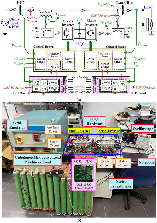
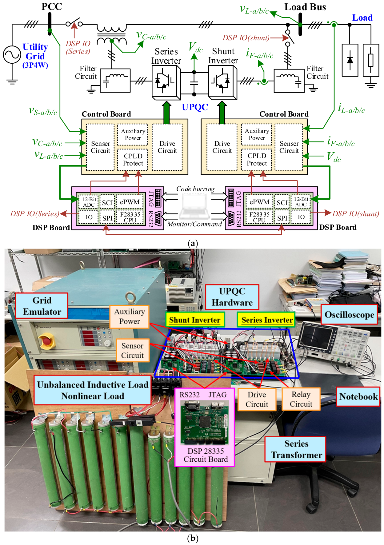
The UPQC control platform is shown in Figure 5, and the architecture of its DSP-based hardware is illustrated in Figure 5a. The shunt and series inverters are each equipped with dedicated digital signal processor (DSP) boards and control boards. The signals required by the control strategy are measured by the sensing circuits and fed to the analog-to-digital converter (ADC) modules, thereby providing the DSPs with the necessary inputs for control computation. The two control units exchange data and coordinate their operations through the serial peripheral interface (SPI) modules of their respective DSPs. A photograph of the experimental setup is provided in Figure 5b, while the UPQC system specifications are summarized in Table 1. To evaluate the compensation performance of the proposed CWFNN-AMF controller, two composite distorted loads, denoted as RL1 and RL2, are configured on the load side. RL1 comprises unbalanced inductive load 1 and nonlinear load 1, whereas RL2 comprises unbalanced inductive load 2 and nonlinear load 2. In addition, two grid-voltage disturbances are imposed separately: a single-phase grid-voltage sag to 0.5 per unit (p.u.) and a three-phase grid-voltage swell to 1.3 p.u. The grid-current unbalance ratio, , is introduced to evaluate the effectiveness of three-phase grid-current compensation and is defined as follows:
where , , and denote the maximum, minimum, and average values of the three-phase grid currents, respectively. A lower value of indicates more effective compensation of three-phase grid-current unbalance.
Figure 5.
UPQC control platform. (a) Block diagram of DSP-based UPQC. (b) Photo of experimental setup.
Table 1.
Specifications of UPQC system.
The experimental evaluation of the UPQC comprises steady-state and dynamic operating conditions. Under steady-state conditions, grid-current compensation is evaluated with each distorted load connected. Under dynamic conditions, a load transition, a grid-voltage sag, and a three-phase grid-voltage swell are examined separately, while the distorted load remains connected. The dynamic performance of current and voltage compensation is evaluated to verify the effectiveness of the UPQC in maintaining overall grid power quality.
The PI gains were determined through an iterative empirical tuning procedure based on the DC-link voltage settling time, steady-state error, and oscillatory response. The final gains used in the experiments were and . The FNN controller was trained using the same two-stage procedure as that used for the corresponding fuzzy-network parameters of the CWFNN-AMF controller. This procedure comprises pre-training and online adaptation.
4.2. Steady-State Experimental Results
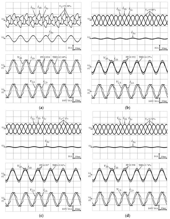
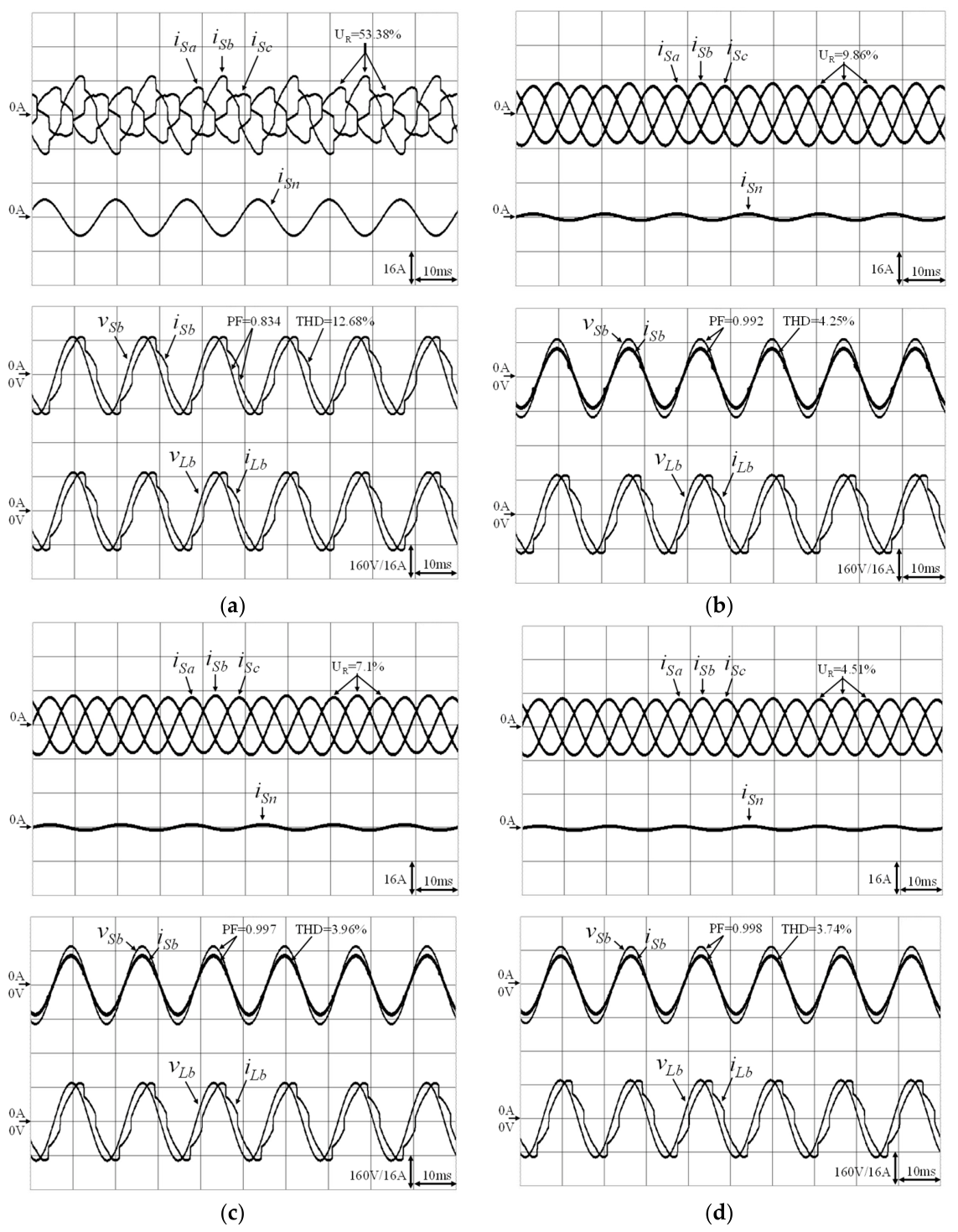
The steady-state experimental results obtained under distorted load RL2 are presented in Figure 6. Without UPQC compensation, the three-phase grid currents are severely distorted and unbalanced, resulting in a substantial neutral current, as shown in Figure 6a. The grid-current unbalance ratio, ; phase-b PF; phase-b grid-current THD; and neutral-current magnitude, , are 53.38%, 0.834, 12.68%, and 5.64 A, respectively. With the PI controller, these values improve to 9.86%, 0.992, 4.25%, and 1.06 A, respectively, as shown in Figure 6b. Further improvements are obtained using the FNN controller, yielding corresponding values of 7.10%, 0.997, 3.96%, and 0.89 A, as shown in Figure 6c. The proposed CWFNN-AMF controller achieves the best compensation performance, reducing , THD, and to 4.51%, 3.74%, and 0.69 A, respectively, while increasing the PF to 0.998, as shown in Figure 6d. This improvement is attributed to the integration of the rapid convergence and nonlinear approximation capabilities of the WFNN, the adaptive compensation mechanism of the CFNN, and the enhanced learning capability of AMFs. The experimental results for loads RL1 and RL2 are summarized in Table 2 and confirm the improved steady-state compensation performance of the proposed controller.
Figure 6.
Steady-state experimental results under load RL2: (a) Without compensation, (b) PI controller, (c) FNN controller, and (d) CWFNN-AMF controller.
Table 2.
Summary of the THD, PF, and current unbalance ratio of the three-phase grid currents under distorted loads RL1 and RL2.
4.3. Dynamic Experimental Results
Under dynamic operating conditions, distorted load RL2 is initially connected to the grid feeder, and three disturbance scenarios are considered: (1) load transition from RL2 to RL1, (2) phase-a grid-voltage sag to 0.5 p.u., and (3) three-phase grid-voltage swell to 1.3 p.u.
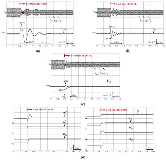
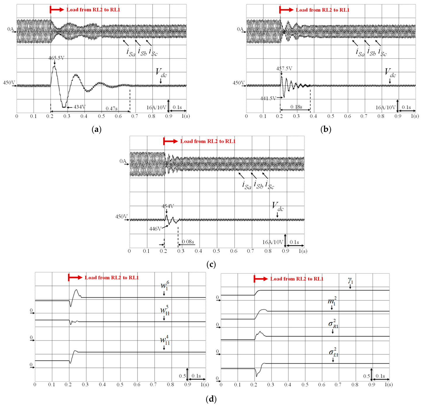
The responses to the load transition from RL2 to RL1 are presented in Figure 7. Under PI control, the slow recovery of the DC-link voltage, , causes pronounced transient disturbances in the three-phase grid currents. The DC-link voltage varies between 434 and 465.5 V and settles within 0.47 s. Under FNN control, the DC-link voltage range is narrowed to 441.5–457.5 V, and the settling time is reduced to 0.18 s. With the proposed CWFNN-AMF controller, the DC-link voltage range is further narrowed to 446–454 V, and the settling time decreases to 0.08 s. The parameter trajectories in Figure 7d demonstrate the online adaptation of the CWFNN-AMF controller during the RL2-to-RL1 load transition. The displayed parameters include , and , where is calculated from the compensatory operators, and , using (16). Online adaptation is initiated immediately after the load transition, and the network parameters rapidly converge to values appropriate for the new operating condition. This adaptation enables the controller to generate the required synchronous q-axis current control signal, , thereby accelerating DC-link voltage recovery.
Figure 7.
Dynamic experimental results during load transition from RL2 to RL1: (a) PI controller, (b) FNN controller, (c) CWFNN-AMF controller, and (d) responses of CWFNN-AMF network parameters.
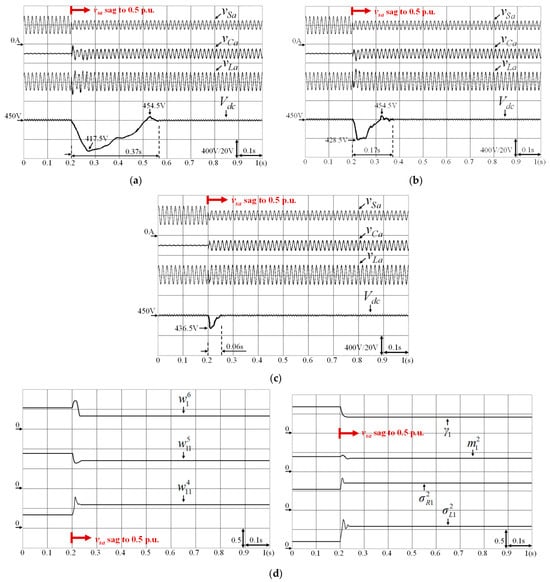
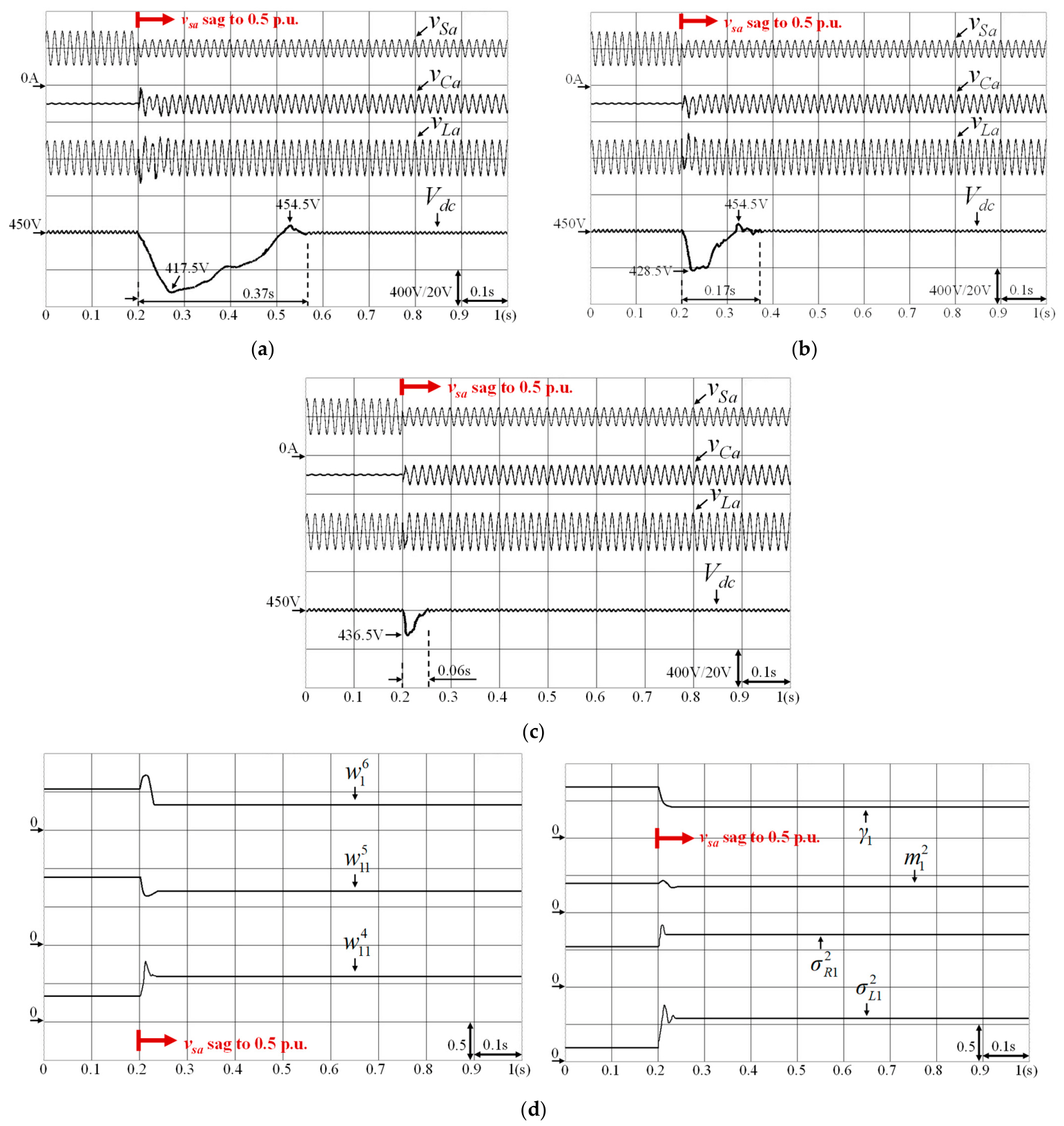
The responses to the phase-a grid-voltage sag are presented in Figure 8. Before the sag, the series compensation voltages remain close to zero. When the phase-a grid voltage, , decreases to 0.5 p.u., the series inverter generates the required phase-a compensation voltage, , through the series transformer to maintain the phase-a load voltage, . Under PI control, the DC-link voltage varies between 417.5 and 454.5 V and settles within 0.37 s. The resulting fluctuation in the series compensation voltage causes load-voltage distortion over several cycles. Under FNN control, the DC-link voltage range is narrowed to 428.5–454 V, and the settling time is reduced to 0.17 s. With CWFNN-AMF control, the minimum DC-link voltage increases to 436.5 V, no overshoot is observed, and the settling time is further reduced to 0.06 s. Consequently, the load-voltage disturbance is confined to one cycle. The parameter trajectories in Figure 8d show that the network parameters are adjusted immediately after the phase-a voltage sag and rapidly converge to values appropriate for the disturbed operating condition. This online adjustment enhances DC-link voltage regulation and series voltage compensation, thereby limiting the influence of the grid-voltage sag on the load voltage.
Figure 8.
Dynamic experimental results during phase-a grid-voltage sag to 0.5 p.u.: (a) PI controller, (b) FNN controller, (c) CWFNN-AMF controller, and (d) responses of CWFNN-AMF network parameters.
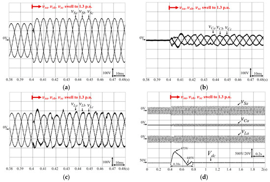
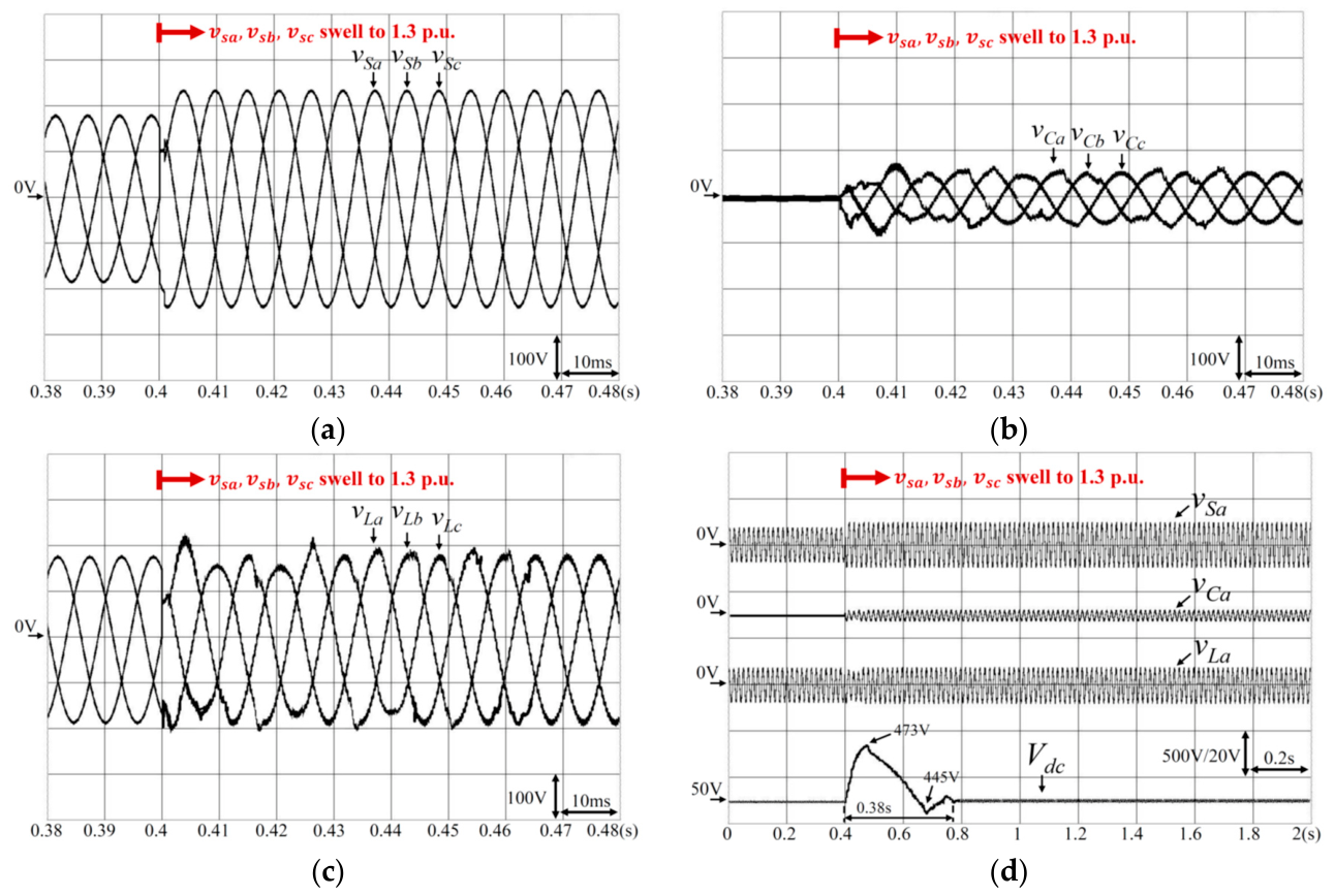
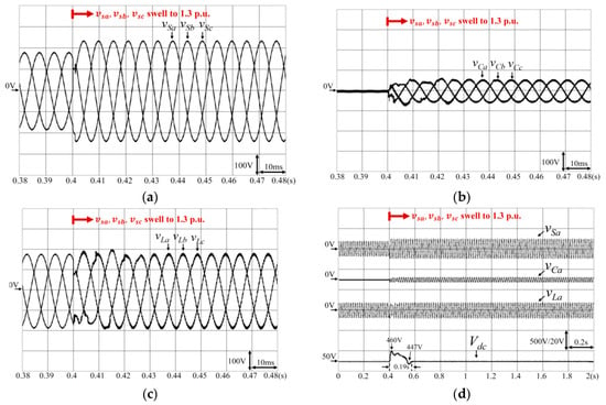
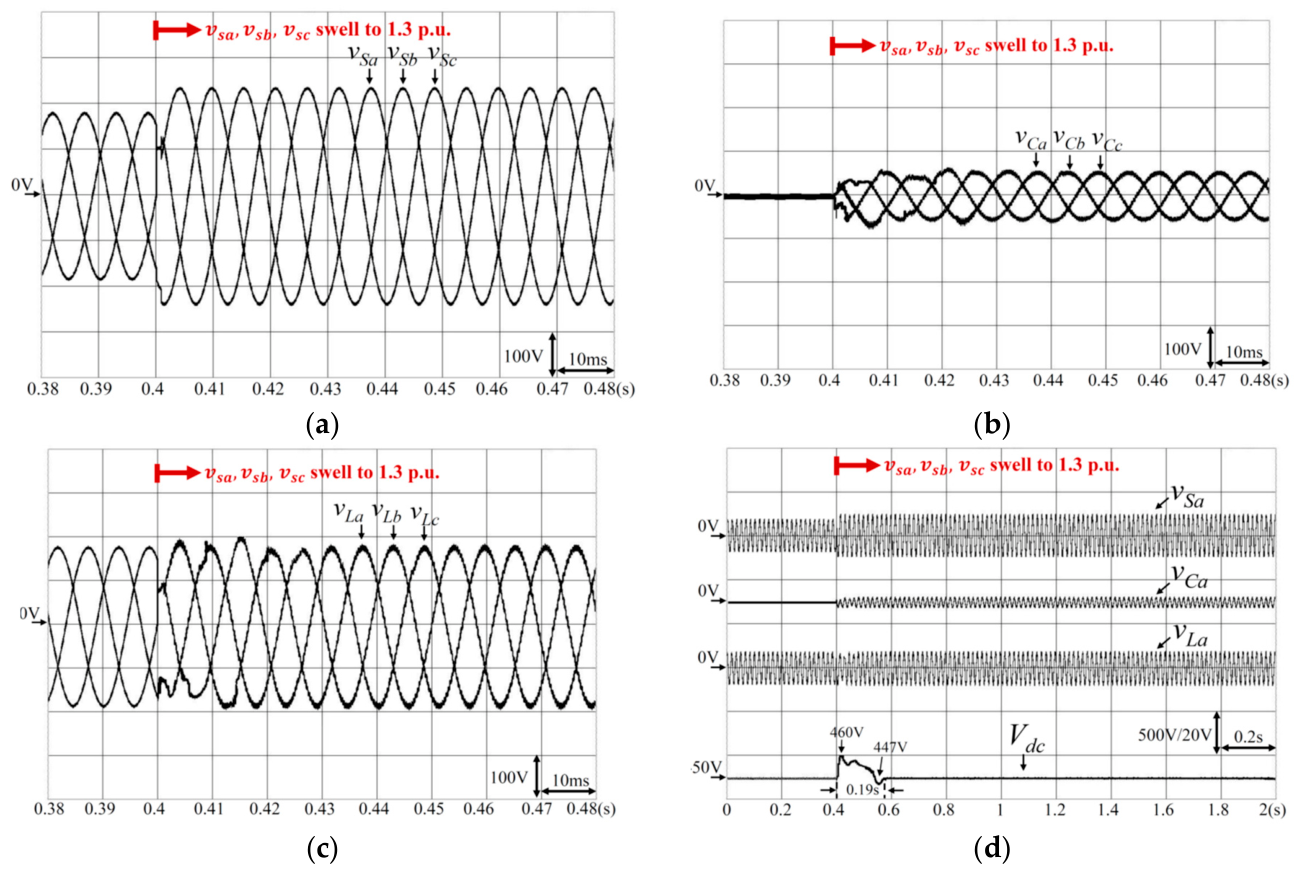
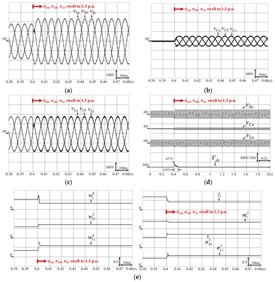
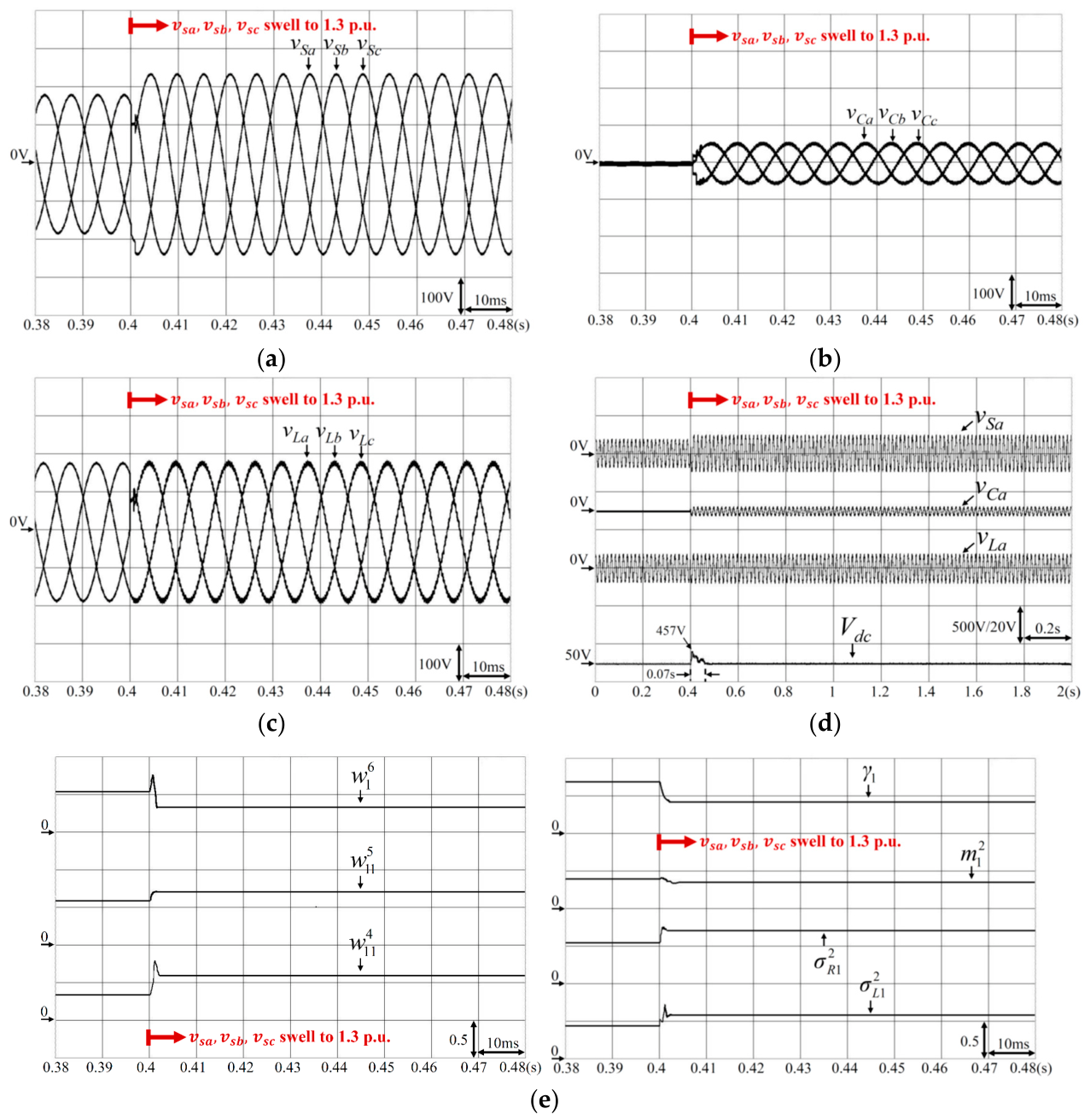
The responses to the three-phase grid-voltage swell are presented in Figure 9, Figure 10 and Figure 11 for the PI, FNN, and CWFNN-AMF controllers, respectively. Initially, the three-phase grid voltages, , remain at 1.0 p.u., and the three-phase series compensation voltages, are approximately zero, indicating that the series inverter compensates only for minor system disturbances. When the three-phase grid voltages increase to 1.3 p.u. at 0.4 s, the series inverter generates the required three-phase compensation voltages, , through the series transformers to maintain the three-phase load voltages, , at 1.0 p.u. Under PI control, as shown in Figure 9, the DC-link voltage varies between 445 and 473 V and settles within 0.38 s. The relatively large and prolonged DC-link voltage excursion results in pronounced transient deviations in the load voltages. Under FNN control, as shown in Figure 10, the DC-link voltage range is narrowed to 447–460 V, and the settling time is reduced to 0.19 s. With the CWFNN-AMF controller, as shown in Figure 11, the maximum DC-link voltage is limited to 457 V, no undershoot below the reference value is observed, and the settling time is further reduced to 0.07 s. The parameter trajectories in Figure 11e show that online adaptation is initiated immediately after the voltage swell. The rapid convergence of the network parameters improves DC-link voltage regulation and enables the three-phase load-voltage magnitudes to return rapidly to 1.0 p.u.
Figure 9.
Dynamic experimental results of the UPQC with PI control during three-phase grid-voltage swell to 1.3 p.u.: (a) three-phase grid voltages; (b) three-phase series compensation voltages; (c) three-phase load voltages; and (d) phase-a grid voltage, series compensation voltage, load voltage, and DC-link voltage.
Figure 10.
Dynamic experimental results of the UPQC with FNN control during three-phase grid-voltage swell to 1.3 p.u.: (a) three-phase grid voltages; (b) three-phase series compensation voltages; (c) three-phase load voltages; and (d) phase-a grid voltage, series compensation voltage, load voltage, and DC-link voltage.
Figure 11.
Dynamic experimental results of the UPQC with CWFNN-AMF control during three-phase grid-voltage swell to 1.3 p.u.: (a) three-phase grid voltages; (b) three-phase series compensation voltages; (c) three-phase load voltages; (d) phase-a grid voltage, series compensation voltage, load voltage, and DC-link voltage; and (e) CWFNN-AMF network-parameter responses.
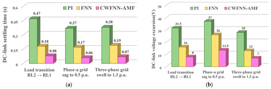
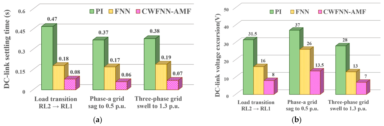
The comparative results for the three dynamic scenarios are summarized in Figure 12 in terms of the DC-link voltage settling time and DC-link voltage excursion. The proposed CWFNN-AMF controller achieves shorter settling times and smaller DC-link voltage excursions than the PI and FNN controllers under all three disturbance scenarios. These improvements result from the rapid convergence and nonlinear approximation capabilities of the WFNN, the adaptive compensation mechanism of the CFNN, and the enhanced learning capability provided by the AMFs. Furthermore, the parameter trajectories in Figure 7d, Figure 8d and Figure 11e, together with the corresponding DC-link voltage responses, show that the online parameters settle and the DC-link voltage returns to its reference value under all tested disturbances. These experimental observations complement the conditional local convergence analysis presented in Section 3.3, which is valid under the stated assumptions. These experimental results verify the effectiveness of the proposed UPQC control strategy in compensating for current and voltage disturbances.
Figure 12.
Comparison of UPQC performance using different controllers under dynamic operating conditions: (a) DC-link voltage settling time and (b) DC-link voltage excursion.
The real-time controllers are implemented on TMS320F28335 DSPs operating at 150 MHz. The execution times are measured using the clock tool in Texas Instruments Code Composer Studio (CCS) v8. The execution cycles and execution times of the PI, FNN, and CWFNN-AMF controllers are summarized in Table 3. For the CWFNN-AMF controller, the measured execution time includes network inference, backpropagation, and the online update of all eight parameter groups. The proposed CWFNN-AMF controller requires 4158 execution cycles, corresponding to an execution time of 27.72 μs. At the sampling frequency of 10 kHz, the available sampling interval is 100 μs. Therefore, the proposed controller can be executed within each sampling interval, confirming the feasibility of real-time implementation.
Table 3.
Computation times of the UPQC with PI, FNN, and proposed CWFNN-AMF controllers.
4.4. Experimental Repeatability and Statistical Analysis
To assess the repeatability of the experimental results, each operating condition was repeatedly tested using the same hardware configuration, controller settings, sampling frequency, load conditions, and disturbance settings. Three complete experimental records for each operating condition were retained and used for quantitative statistical analysis. For the steady-state experiments, the grid-current unbalance ratio (), phase-b grid-current THD, and phase-b PF were evaluated. For the dynamic experiments, the maximum and minimum DC-link voltages, DC-link voltage excursion, and settling time were evaluated. The DC-link voltage excursion is defined as
where and denote the maximum and minimum DC-link voltages measured during the corresponding dynamic disturbance, respectively. The individual measurements obtained from the three retained experimental records are presented in Table 4 and Table 5.
Table 4.
Repeated steady-state experimental results for distorted loads RL1 and RL2.
Table 5.
Repeated dynamic experimental results under the load transition, voltage sag, and voltage swell.
Based on the individual measurements in Table 4 and Table 5, the mean value and sample standard deviation were calculated for each performance index. The sample standard deviation is defined as
where is the value obtained from the rth retained experimental record, is the corresponding sample mean, and is the number of retained experimental records. The statistical summaries of the repeated steady-state and dynamic experimental results are presented in Table 6 and Table 7, respectively.
Table 6.
Statistical summary of the repeated steady-state experimental results (mean ± sample standard deviation, .
Table 7.
Statistical summary of the repeated dynamic experimental results (mean ± sample standard deviation, .
The repeated-trial results show that the relative performance ranking among the three controllers remains unchanged across all retained experimental records. Under both steady-state load conditions, the CWFNN-AMF controller consistently achieves the lowest grid-current unbalance ratio and phase-b THD while maintaining a near-unity PF. For load RL1, the proposed controller reduces the mean grid-current unbalance ratio by approximately 50.7% and 34.3% compared with the PI and FNN controllers, respectively. The corresponding reductions in phase-b THD are approximately 11.2% and 4.1%. For load RL2, the mean grid-current unbalance ratio is reduced by approximately 54.2% and 36.7%, while the phase-b THD is reduced by approximately 11.5% and 5.8%, relative to the PI and FNN controllers, respectively.
Under the three dynamic disturbance scenarios, the CWFNN-AMF controller consistently produces the smallest DC-link voltage excursion and the shortest settling time. Compared with the PI controller, the proposed controller reduces the mean DC-link voltage excursion by approximately 64.0–75.3% and the mean settling time by approximately 81.3–82.9%. Relative to the FNN controller, the corresponding reductions are approximately 46.8–52.1% and 56.4–62.5%, respectively. Moreover, the trial-to-trial variations are small relative to the performance differences among the three controllers. These results demonstrate that the improved performance of the CWFNN-AMF controller is consistently reproduced rather than being attributable to a single experimental realization, thereby supporting the repeatability and reliability of the reported experimental results.
4.5. Sensitivity Analysis of the Regularization Parameter
The regularization parameter, , in the normalized adaptive learning-rate law prevents the denominator from approaching zero and influences the magnitude of the parameter updates. To evaluate its influence on the experimentally observed settling behavior and dynamic performance of the CWFNN-AMF controller, a sensitivity analysis was conducted. The nominal value used in the DSP implementation was . Five values, , , , , and , were evaluated, while all other controller settings and experimental conditions remained unchanged.
The sensitivity analysis was performed under the RL2-to-RL1 load transition, phase-a grid-voltage sag to 0.5 p.u., and three-phase grid-voltage swell to 1.3 p.u. The maximum and minimum DC-link voltages, DC-link voltage excursion, and settling time obtained under these conditions are summarized in Table 8.
Table 8.
Sensitivity of the CWFNN-AMF controller to the regularization parameter under the dynamic disturbance scenarios.
For the RL2-to-RL1 load transition, the DC-link voltage excursion ranges from 8.0 to 8.6 V, while the settling time ranges from 0.08 to 0.09 s. Under the phase-a grid-voltage sag, the corresponding ranges are 13.5–14.0 V and 0.06–0.08 s, respectively. Under the three-phase grid-voltage swell, the corresponding ranges are 7.0–7.8 V and 0.07–0.08 s. The DC-link voltage settles within 0.09 s in all tested cases. Although variations in produce minor differences in the transient responses, comparable DC-link voltage regulation is maintained throughout the investigated range. Across the three scenarios, the nominal value, , yields either the smallest or a jointly smallest voltage excursion and settling time. These results indicate that the proposed controller exhibits limited sensitivity to the regularization parameter and maintains robust dynamic performance over the investigated range.
5. Conclusions
This study proposes and implements a UPQC to improve overall power quality. During power exchange between the series and shunt inverters, instantaneous power flows into or out of the common DC-link capacitor. Consequently, grid-voltage distortion or load variations may degrade the compensation stability and transient response of the UPQC. To address this issue, the proposed CWFNN-AMF controller is employed for DC-link voltage regulation in place of the conventional PI and FNN controllers, thereby improving the overall compensation performance. Experimental results demonstrate that the CWFNN-AMF-controlled UPQC improves the compensation of unbalanced three-phase grid currents under steady-state conditions. Under dynamic conditions, significant improvements are also achieved in the transient responses of the load voltages, grid currents, and DC-link voltage. The major contributions of this study are summarized as follows: (i) development of a UPQC for coordinated current and voltage compensation; (ii) development of an online-trained CWFNN-AMF controller for DC-link voltage regulation; and (iii) integration of the proposed controller with the UPQC to improve power quality and DC-link voltage regulation. Although the experimental results validate the effectiveness of the proposed controller, the present study is limited to a laboratory-scale prototype. Future work will focus on evaluating the scalability and practical applicability of the proposed control strategy in higher-power UPQC systems.
Author Contributions
Conceptualization, C.-C.C. and J.-H.C.; methodology, C.-C.C. and J.-H.C.; validation, C.-C.C. and J.-H.C.; formal analysis, C.-C.C., J.-H.C., and K.-H.T.; investigation, J.-H.C. and K.-H.T.; writing—original draft preparation, J.-H.C. and K.-H.T.; writing—review and editing, J.-H.C. and K.-H.T. All authors have read and agreed to the published version of the manuscript.
Funding
This research was funded by the National Atomic Research Institute of Taiwan, grant number 115A015.
Data Availability Statement
The original contributions presented in this study are included in the article. Further inquiries can be directed to the corresponding authors.
Conflicts of Interest
The authors declare no conflicts of interest.
References
- Benali, A.; Khiat, M.; Allaoui, T.; Denai, M. Power quality improvement and low voltage ride through capability in hybrid wind-PV farms grid-connected using dynamic voltage restorer. IEEE Access 2018, 6, 68634–68648. [Google Scholar] [CrossRef] [Scilit]
- Biricik, S.; Komurcugil, H.; Tuyen, N.D.; Basu, M. Protection of sensitive loads using sliding mode controlled three-phase DVR with adaptive notch filter. IEEE Trans. Ind. Electron. 2019, 66, 5465–5475. [Google Scholar] [CrossRef] [Scilit]
- Lin, L.; He, J.; Xu, C. Analysis on circulating current and split capacitor voltage balance for modular multilevel converter based three-phase four-wire split capacitor DSTATCOM. J. Mod. Power Syst. Clean Energy 2021, 9, 657–667. [Google Scholar] [CrossRef] [Scilit]
- Moghassemi, A.; Padmanaban, S.; Ramachandaramurthy, V.K.; Mitolo, M.; Benbouzid, M. A novel solar photovoltaic fed TransZSI-DVR for power quality improvement of grid-connected PV systems. IEEE Access 2021, 9, 7263–7279. [Google Scholar] [CrossRef] [Scilit]
- Prasad, K.K.; Myneni, H.; Kumar, G.S. Power quality improvement and PV power injection by DSTATCOM with variable DC-link voltage control from RSC-MLC. IEEE Trans. Sustain. Energy 2019, 10, 876–885. [Google Scholar] [CrossRef] [Scilit]
- Al-Gahtani, S.F.; Barnawi, A.B.; Azazi, H.Z.; Irshad, S.M.; Bhutto, J.K.; Majahar, H.M.; Salem, E.Z.M. A new technique implemented in synchronous reference frame for DVR control under severe sag and swell conditions. IEEE Access 2022, 10, 25565–25579. [Google Scholar] [CrossRef] [Scilit]
- da Silva, S.A.O.; Modesto, R.A. A comparative analysis of SRF-based controllers applied to active power line conditioners. In Proceedings of the IECON 2008—34th Annual Conference of IEEE Industrial Electronics Society, Orlando, FL, USA, 10–13 November 2008; pp. 405–410. [Google Scholar]
- da Silva, S.A.O.; Donoso-Garcia, P.F.; Cortizo, P.C.; Seixas, P.F. A comparative analysis of control algorithms for three-phase line-interactive UPS systems with series-parallel active power-line conditioning using SRF method. In Proceedings of the 2000 IEEE 31st Annual Power Electronics Specialists Conference (PESC 2000), Galway, Ireland, 18–23 June 2000; Volume 2, pp. 1023–1028. [Google Scholar]
- Czarnecki, L.S. Instantaneous reactive power p-q theory and power properties of three-phase systems. IEEE Trans. Power Deliv. 2006, 21, 362–367. [Google Scholar] [CrossRef] [Scilit]
- Lee, W.C.; Lee, D.M.; Lee, T.K. New control scheme for a unified power-quality compensator-Q with minimum active power injection. IEEE Trans. Power Deliv. 2010, 25, 1068–1076. [Google Scholar] [CrossRef] [Scilit]
- Kesler, M.; Ozdemir, E. Synchronous-reference-frame-based control method for UPQC under unbalanced and distorted load conditions. IEEE Trans. Ind. Electron. 2011, 58, 3967–3975. [Google Scholar] [CrossRef] [Scilit]
- Dash, S.K.; Ray, P.K. A new PV-open-UPQC configuration for voltage-sensitive loads utilizing novel adaptive controllers. IEEE Trans. Ind. Inform. 2021, 17, 421–429. [Google Scholar] [CrossRef] [Scilit]
- Patjoshi, R.K.; Mahapatra, K. High-performance unified power quality conditioner using command generator tracker-based direct adaptive control strategy. IET Power Electron. 2016, 9, 1267–1278. [Google Scholar] [CrossRef] [Scilit]
- Patjoshi, R.K.; Mahapatra, K. High-performance unified power quality conditioner using non-linear sliding mode and new switching dynamics control strategy. IET Power Electron. 2017, 10, 863–874. [Google Scholar] [CrossRef] [Scilit]
- Karanki, S.B.; Geddada, N.; Mishra, M.K.; Kumar, B.K. A modified three-phase four-wire UPQC topology with reduced DC-link voltage rating. IEEE Trans. Ind. Electron. 2013, 60, 3555–3566. [Google Scholar] [CrossRef] [Scilit]
- Zhu, D.; Tan, Z. A new method to design the DC-voltage controller for UPQC. In Proceedings of the 2010 2nd IEEE International Symposium on Power Electronics for Distributed Generation Systems (PEDG 2010), Hefei, China, 16–18 June 2010; pp. 196–199. [Google Scholar]
- Lin, Y.Y.; Chang, J.Y.; Lin, C.T. A TSK-type-based self-evolving compensatory interval type-2 fuzzy neural network (TSCIT2FNN) and its applications. IEEE Trans. Ind. Electron. 2014, 61, 447–459. [Google Scholar] [CrossRef] [Scilit]
- Lin, C.J.; Chen, C.H. Identification and prediction using recurrent compensatory neuro-fuzzy systems. Fuzzy Sets Syst. 2005, 150, 307–330. [Google Scholar] [CrossRef] [Scilit]
- Lin, F.J.; Tan, K.H.; Lai, Y.K.; Luo, W.C. Intelligent PV power system with unbalanced current compensation using CFNN-AMF. IEEE Trans. Power Electron. 2019, 34, 8588–8598. [Google Scholar] [CrossRef] [Scilit]
- Tan, K.H.; Lin, F.J.; Tsai, C.Y.; Chang, Y.R. A distribution static compensator using a CFNN-AMF controller for power quality improvement and DC-link voltage regulation. Energies 2018, 11, 1996. [Google Scholar] [CrossRef] [Scilit]
- Lin, F.J.; Tan, K.H.; Luo, W.C.; Xiao, G.D. Improved LVRT performance of PV power plant using recurrent wavelet fuzzy neural network control for weak grid conditions. IEEE Access 2020, 8, 69346–69358. [Google Scholar] [CrossRef] [Scilit]
- El-Sousy, F.F.M.; Amin, M.M.; Mohammed, O.A. Robust optimal control of high-speed permanent-magnet synchronous motor drives via self-constructing fuzzy wavelet neural network. IEEE Trans. Ind. Appl. 2021, 57, 999–1013. [Google Scholar] [CrossRef] [Scilit]
- Tan, K.H. Squirrel cage induction generator system using wavelet Petri fuzzy neural network control for wind power applications. IEEE Trans. Power Electron. 2016, 31, 5242–5254. [Google Scholar] [CrossRef] [Scilit]
- Lin, F.J.; Hung, Y.C.; Ruan, K.C. An intelligent second-order sliding-mode control for an electric power steering system using a wavelet fuzzy neural network. IEEE Trans. Fuzzy Syst. 2014, 22, 1598–1611. [Google Scholar] [CrossRef] [Scilit]
- Lin, F.J.; Lu, K.C.; Ke, T.H.; Yang, B.H.; Chang, Y.R. Reactive power control of three-phase grid-connected PV system during grid faults using Takagi–Sugeno–Kang probabilistic fuzzy neural network control. IEEE Trans. Ind. Electron. 2015, 62, 5516–5528. [Google Scholar] [CrossRef] [Scilit]
- Aryanezhad, M.; Ostadaghaee, E. Robustness of unified power quality conditioner by neural network based on admittance estimation. Appl. Soft Comput. 2021, 107, 107420. [Google Scholar] [CrossRef] [Scilit]
- Mahar, H.; Munir, H.M.; Soomro, J.B.; Akhtar, F.; Hussain, R.; Elnaggar, M.F.; Kamel, S.; Guerrero, J.M. Implementation of ANN controller based UPQC integrated with microgrid. Mathematics 2022, 10, 1989. [Google Scholar] [CrossRef] [Scilit]
- Srimatha, S.; Mallala, B.; Upendar, J. A novel ANFIS-controlled customized UPQC device for power quality enhancement. J. Electr. Syst. Inf. Technol. 2023, 10, 55. [Google Scholar] [CrossRef] [Scilit]
- Singh, A.R.; Dashtdar, M.; Bajaj, M.; Garmsiri, R.; Blazek, V.; Prokop, L.; Misak, S. AI-enhanced power quality management in distribution systems: Implementing a dual-phase UPQC control with adaptive neural networks and optimized PI controllers. Artif. Intell. Rev. 2024, 57, 311. [Google Scholar] [CrossRef] [Scilit]
- Chen, L.; Zhou, J.; Zhai, J.; Yang, L.; Qian, X.; Tao, Z. Continuous-control-set model predictive control strategy for MMC-UPQC under non-ideal conditions. Energies 2025, 18, 2946. [Google Scholar] [CrossRef] [Scilit]
- Zhao, X.; Dang, H.; Li, M.; Wang, X.; Ding, H.; Guo, X. Performance enhancement for unified power quality conditioner using passivity fractional-order sliding mode control. IEEE Trans. Consum. Electron. 2025, 71, 2675–2688. [Google Scholar] [CrossRef] [Scilit]
- Mei, Y.; Xu, J.; Peng, C.; Kong, W.; Peng, G.; Song, G. Voltage quality enhancement of distribution network based on unified power quality conditioner with BESS. Front. Energy Res. 2024, 12, 1472503. [Google Scholar] [CrossRef] [Scilit]
- Ghosh, A.; Ledwich, G. Power Quality Enhancement Using Custom Power Devices; Kluwer Academic Publishers: Boston, MA, USA, 2002. [Google Scholar]
- Tan, K.H.; Chen, J.H.; Lee, Y.D. Intelligent controlled dynamic voltage restorer for improving transient voltage quality. IEEE Access 2023, 11, 74686–74701. [Google Scholar] [CrossRef] [Scilit]

Disclaimer/Publisher’s Note: The statements, opinions and data contained in all publications are solely those of the individual author(s) and contributor(s) and not of MDPI and/or the editor(s). MDPI and/or the editor(s) disclaim responsibility for any injury to people or property resulting from any ideas, methods, instructions or products referred to in the content. |
© 2026 by the authors. Licensee MDPI, Basel, Switzerland. This article is an open access article distributed under the terms and conditions of the Creative Commons Attribution (CC BY) license.