


Abstract
For the problem of additional copper loss, iron loss, and efficiency degradation caused by current harmonics in surface-mounted permanent magnet synchronous motor (SPMSM), this study proposes a novel optimization strategy based on harmonic current and the conventional loss minimization control (LMC) strategy, namely Harmonic-Current-Inclusive Loss Minimization Control (HCI-LMC). For the 5th, 7th, and 11th current components, a compensatory harmonic voltage injection scheme is adopted for suppression. Simulation studies are conducted to verify the effectiveness of the proposed optimization strategy. The total harmonic distortion (THD) of the stator current is reduced from 14.87% to 1.36%, and the amplitudes of the 5th, 7th, and 11th harmonics are attenuated by 82.6%, 80.0%, and 79.3%, respectively. The results indicate that HCI-LMC can significantly suppress harmonic losses and improve the overall motor efficiency by 1.32% compared with the conventional LMC strategy.
1. Introduction
Electric vertical take-off and landing aircraft (eVTOL) have attracted increasing attention with the rapid development of Urban Air Mobility and Low-Altitude Economy. Compared with conventional electric-drive applications, eVTOL propulsion imposes more stringent requirements on the electric propulsion system (EPS), including high efficiency, high power density, lightweight design, and high reliability. Owing to its high energy density, high efficiency, and compact structure, the permanent magnet synchronous motor (PMSM) has become one of the most important candidates for eVTOL EPS. Studies on motor design for eVTOL applications have shown that the power density and efficiency of propulsion motors can be effectively improved by optimizing winding configurations, permanent magnet arrangements, and electromagnetic topologies [1]. Meanwhile, studies on aviation electrification and materials for eVTOL aircraft have also indicated that EPS design involves comprehensive trade-offs among efficiency, mass, safety, thermal management, and cost [2,3]. Therefore, achieving high-efficiency operation of PMSM under limited installation space, restricted cooling capability, and stringent current-capacity constraints is a key issue in eVTOL EPS.
To improve the operating efficiency of PMSM, various reference-current generation methods have been proposed, among which maximum torque per ampere (MTPA) control and loss minimization control (LMC) are more popular approaches. Conventional MTPA control mainly reduces copper loss by optimizing the distribution of the fundamental dq-axis currents [4]. LMC further incorporates iron loss, equivalent iron-loss resistance, and parameter variations into the optimization process, thereby achieving higher efficiency under broader operating conditions [5,6]. In recent years, LMC based on equivalent iron-loss resistance methods has been developed for interior PMSM to reduce the implementation complexity of conventional LMC. Variable-parameter models and current-decoupling strategies have also been introduced to improve the accuracy of efficiency optimization under wide operating conditions [6,7]. In addition, parameter self-learning and online flux-linkage estimation methods have been employed to enhance parameter identification, state estimation, and control robustness in PMSM drives [8,9]. However, existing efficiency optimization methods still have limitations in the practical operation of high-power-density PMSM. Most of these methods establish loss models and current constraints mainly based on fundamental current components and usually represent the current limit by the magnitude of the fundamental current. When noticeable harmonic components are present in the stator current, this assumption may underestimate the combined contribution of fundamental and harmonic components to the squared current, copper loss, and thermal load. As a result, the obtained optimal current references may not fully satisfy the actual current-capacity constraint.
Harmonic currents in PMSM drive systems generally originate from inverter non-idealities, PWM modulation, and the inherent non-sinusoidal field characteristics of the motor. In a voltage-source inverter (VSI), dead time, switching-device voltage drops, turn-on and turn-off delays, and parasitic capacitances cause the actual output voltage to deviate from the reference voltage, leading to current distortion, especially under low-speed, light-load, and near-zero-current conditions [10,11]. To address this issue, accurate modeling, wide-bandwidth current control, current injection, and online compensation methods have been investigated to reduce the influence of VSI nonlinearity on current control and parameter identification [10,11,12]. On the other hand, harmonic currents can produce additional iron loss in PMSM and may account for a considerable proportion of the total loss in low-torque regions [13]. Studies on rotational magnetic fields and improved iron-loss models have shown that iron loss is closely related to the flux-density trajectory, harmonic magnetic fields, and local magnetization states [14,15]. Moreover, local saturation, slotting effects, and spatial magnetic-field harmonics in the motor can result in non-sinusoidal distributions of air-gap flux density and phase inductance, further inducing harmonic currents and additional local losses [15,16]. Therefore, the actual stator current consists of both fundamental and harmonic components, and the sum of their squared components can better represent the actual levels of current stress, copper loss, and thermal load.
Based on these issues, this study proposed a Harmonic-Current-Inclusive Loss Minimization Control (HCI-LMC) method to improve the current-constraint description of conventional LMC when harmonic currents are considered. Compared with conventional LMC, which mainly used the magnitude of the fundamental current as the current-capacity constraint, the proposed HCI-LMC incorporates the squared terms of selected low-order harmonic currents into the total squared-current constraint. Thus, the current-capacity limit of the motor and inverter accounts for both fundamental and harmonic current components. In PMSM control, the feasible current-vector region is jointly defined by the current and voltage limits; therefore, an upper bound on the total squared current is required to satisfy the inverter current capacity, limit the winding temperature rise, and ensure control feasibility [17]. In this framework, harmonic currents are no longer regarded merely as disturbances to be suppressed, but are treated as important factors affecting the available fundamental current margin and optimal current references. In this study, the dominant low-order harmonic current components are first extracted. The current constraint in LMC is then modified according to the squared-superposition relationship between the fundamental and harmonic currents. Subsequently, under the total current limit, the optimal fundamental dq-axis current references are recalculated. Compared with existing methods that mainly focus on VSI nonlinearity compensation, harmonic iron-loss reduction, parameter identification, or wide-speed-range current regulation [8,10,11,12,13,17], this study further clarifies the relationship among harmonic current, total current capacity, optimal fundamental current, and loss minimization control. As a result, LMC can provide a more reasonable current-constraint description and improved engineering applicability under practical current-distortion conditions.
2. Modeling Method of PMSM
2.1. Equivalent Circuit Model of PMSM Considering Iron Loss
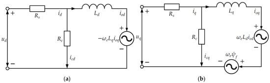
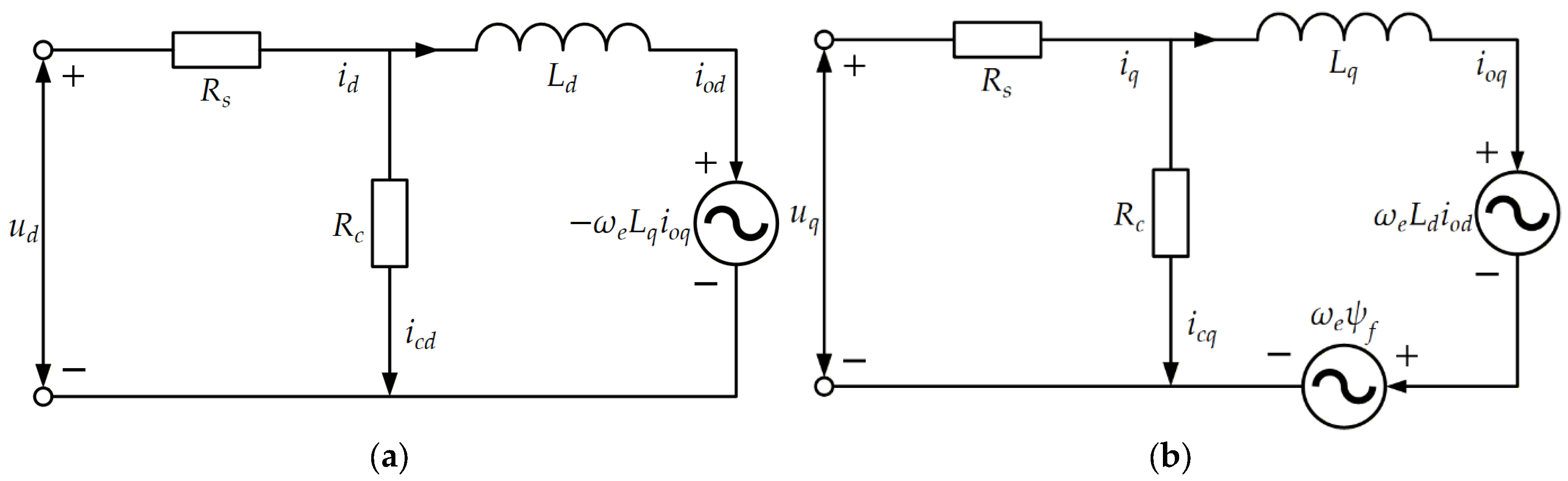
The losses in a PMSM mainly include iron loss, copper loss, mechanical loss, and stray loss. Since mechanical loss and stray loss occupy a small proportion and are influenced by complex factors [6], this study mainly focuses on decreasing iron loss and copper loss. By paralleling an iron-loss resistance, the iron loss is equivalent to the heat generated on the iron-loss resistance, which is calculated as shown in Figure 1 and represented in the equivalent circuit diagram.
Figure 1.
(a) d-axis equivalent circuit diagram, (b) q-axis equivalent circuit diagram.
According to Kirchhoff’s Voltage law, the voltage equation of the PMSM considering iron loss can be obtained as follows:
where and are the d-axis and q-axis components of the stator voltage, and are the d-axis and q-axis components of the stator current, and are the d-axis and q-axis components of the equivalent iron-loss current, and are the d-axis and q-axis components of the torque current, and are the d-axis and q-axis components of inductance. All the above parameters are defined in the dq reference frame. is the stator winding resistance, is the equivalent iron-loss resistance, is the rotor electrical angular velocity, and is the magnetic flux linkage of the permanent magnets.
Substitute Equations (1) and (2) into Equation (3), and we can obtain:
The torque equation is as follows:
where is the electromagnetic torque, is the number of pole pairs.
2.2. Derivation of Harmonic Voltage Equations in Multiple Synchronous Reference Frames
In the case where only the fundamental wave is present, the d-axis and q-axis voltage and current components of the motor are constant. However, when considering nonlinear factors such as inverter dead-time effects and device voltage drops, the motor generates higher-order harmonic components, primarily including the 5th, 7th, 11th, and 13th harmonics. Since the amplitude of the 13th harmonic is relatively small and its impact on the motor can be neglected, this study only considers the 5th, 7th, and 11th harmonics. Among them, the voltage vectors of the 5th and 11th harmonics rotate in the opposite direction to the fundamental voltage vector, representing negative-order harmonics, while the voltage vector of the 7th harmonic rotates in the same direction as the fundamental voltage vector, representing positive-order harmonics. Therefore, the motor’s three-phase voltage can be expressed as follows:
where , , are the three-phase voltages, is the amplitude of fundamental voltage, , , are the amplitudes of 5th, 7th, and 11th harmonic voltages, and , , are the initial phases of the 5th, 7th, and 11th harmonic voltages. All the above parameters are defined in the natural abc reference frame. is the angular velocity.
Then transform Equation (6) into the dq-axis frame:
where and are the d-axis and q-axis components of fundamental stator voltage, , , are the amplitudes of d-axis 5th, 7th, and 11th harmonic stator voltages, , , are the amplitudes of q-axis 5th, 7th, and 11th harmonic stator voltages, and , , are the initial phases of the 5th, 7th, and 11th harmonic stator voltages. All the above parameters are defined in the dq reference frame.
Similarly, the equations for the three-phase currents in the dq-axis frame can be expressed as:
where and are the d-axis and q-axis components of fundamental stator current, , , are the amplitudes of d-axis 5th, 7th, and 11th harmonic stator currents, , , are the amplitudes of q-axis 5th, 7th, and 11th harmonic stator currents, and , , are the initial phases of 5th, 7th, and 11th harmonic stator currents. All the above parameters are defined in the dq reference frame.
Substituting Equation (8) into Equation (4) yields:
where are , , ,.
According to the coordinate transformation principle, the 5th harmonic component becomes a constant in its own synchronous reference frame (i.e., the 5th harmonic synchronous reference frame). Therefore, by neglecting the other AC components, the steady-state voltage equation for the 5th harmonic in this reference frame can be obtained as:
By following this method, the steady-state voltage equations for the 7th and 11th harmonics can be obtained.
2.3. Loss Minimization Control Based on Fundamental Loss Modeling
Under steady-state conditions, when only the fundamental components are considered, the corresponding DC components in the synchronous reference frame are time-invariant, satisfying and . Therefore, Equation (2) for the fundamental components can be expressed as:
where and are the d-axis and q-axis components of the fundamental equivalent iron-loss current, and are the d-axis and q-axis components of the fundamental torque current.
The total loss of the motor, including copper loss and iron loss, is given by:
where is the total loss of fundamental current, is the copper loss of fundamental current, is the iron loss of the fundamental equivalent iron-loss current.
From Equations (1), (5) and (12), the relationships among the current, electromagnetic torque, and equivalent fundamental iron-loss current can be established. Accordingly, the fundamental iron-loss efficiency can be formulated solely in terms of the fundamental current variable , as follows [6]:
When the system is in a steady state, the loss of the PMSM is a function of . For IPMSM, the unequal d- and q-axis inductances introduce saliency effects, making the determination of the optimal d-axis current reference more dependent on motor parameters. These parameters may vary with operating conditions; online identification or parameter adaptation is often required for accurate loss-model-based optimization. To simplify the control design and focus on the proposed optimization strategy, an SPMSM is considered in this study, for which the saliency effect is negligible, and can be assumed. By setting , the minimum loss current instruction is obtained as:
Equation (15) represents the optimal d-axis active current under the minimum loss constraint. However, due to the nonlinear characteristics of the inverter and the distortion of the air-gap magnetic field, the actual d-axis and q-axis currents contain harmonics, which can lead to current distortion and additional harmonic loss [13]. Therefore, the optimal control current at this point must also account for the impact of harmonics.
3. Efficiency Optimization Control Coupled with Harmonic Suppression
3.1. Multiple Synchronous Reference Frame Based Harmonic Extraction Using Low-Pass Filters
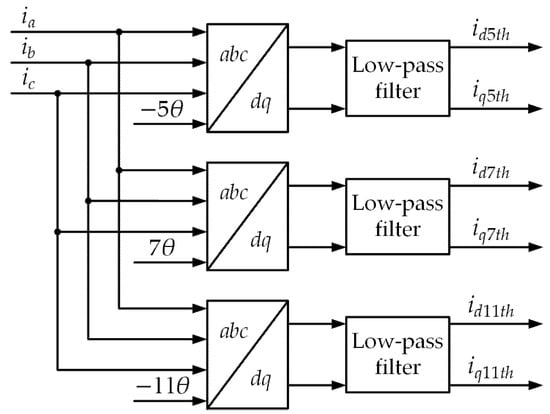
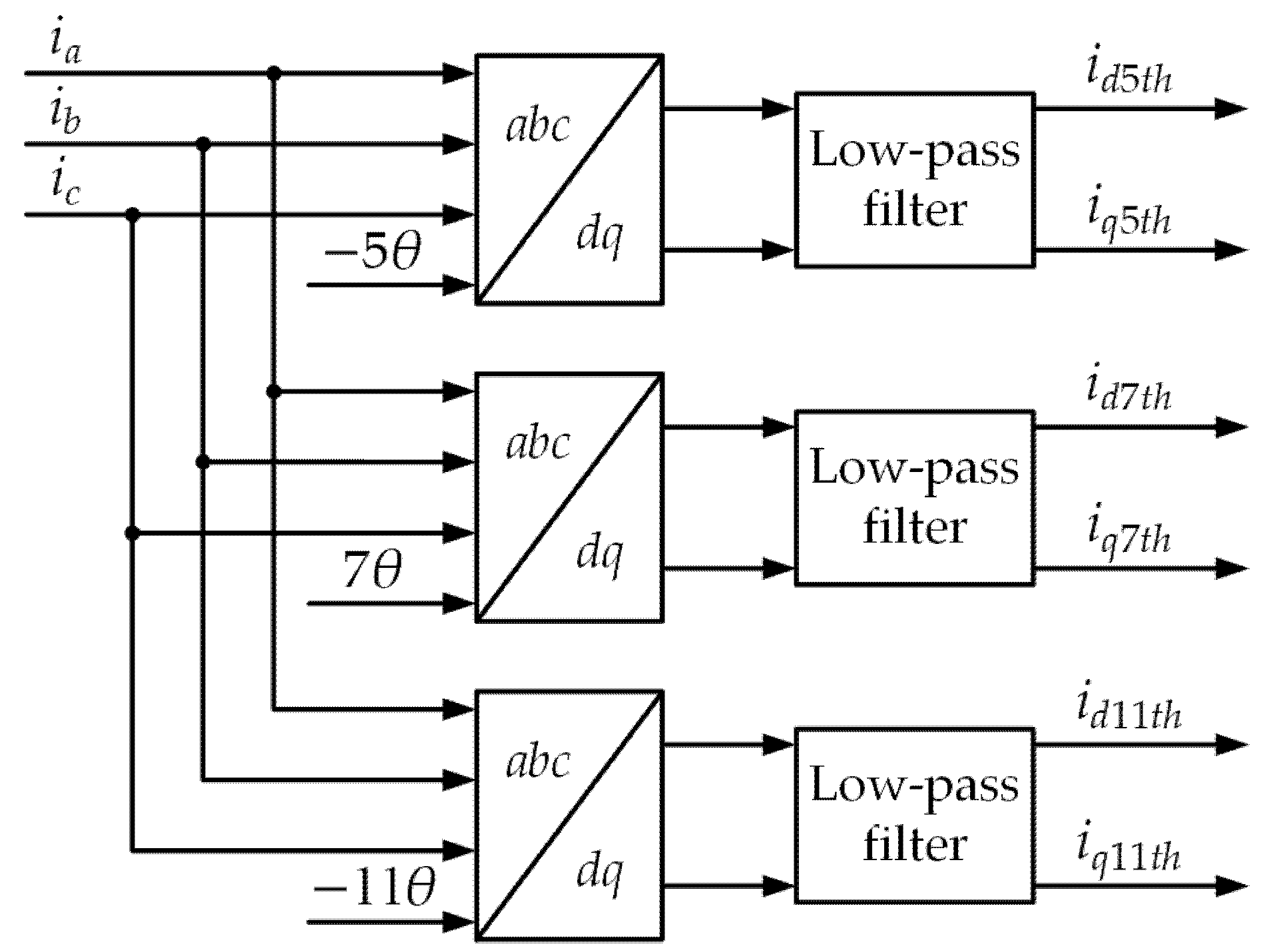
As the 5th, 7th, and 11th harmonic components manifest as DC quantities in their respective synchronous reference frames, while all other components remain AC, a low-pass filter can be used to extract these DC components. This process is illustrated in the block diagram of Figure 2.
Figure 2.
Harmonic extraction module.
3.2. Feedforward Voltage Compensation
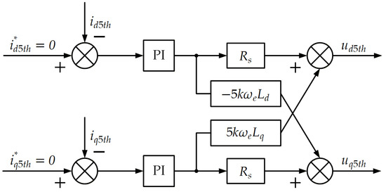
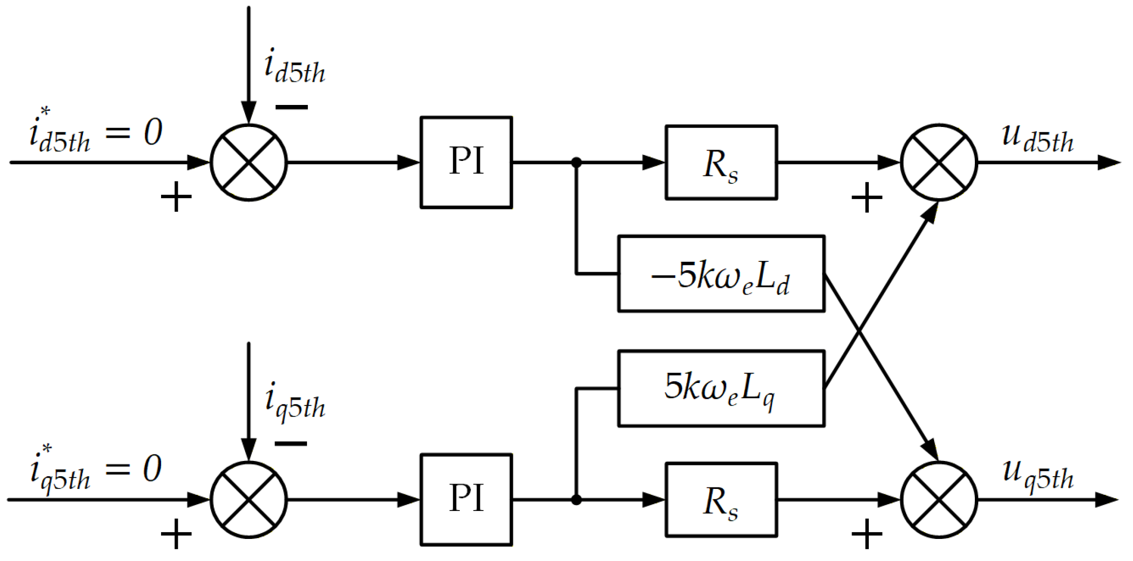
Based on Equation (10), taking the 5th harmonic as an example, a voltage harmonic injection module is constructed as shown in Figure 3.
Figure 3.
5th harmonic voltage suppression module.
The extracted harmonic current is compared with a zero reference, and the resulting error is fed into a PI controller. Then, the product of the PI controller output and the cross-term is added to calculate the compensating voltages and for the 5th harmonic. Afterward, these compensating voltages are transformed into the abc coordinate system and fed into the SVPWM (Space Vector Pulse Width Modulation) module, which enables the injection of the harmonic voltage and achieves harmonic suppression.
Considering the presence of mutual coupling between the d-axis and q-axis in the steady-state harmonic voltage equations of the PMSM, the cross-term product is added after each PI controller based on the steady-state voltage equation. This approach reduces the coupling effect and improves the system’s accuracy.
3.3. Development of the Harmonic Loss Model
The efficiency optimization control incorporating harmonic injection achieves a comprehensive improvement in motor performance by integrating the dual objectives of harmonic suppression and efficiency optimization. The core lies in actively injecting harmonic components to counteract the inherent harmonic components, while dynamically adjusting the current values based on an extended loss model, ensuring that the motor operates at the global optimal efficiency. Compared to traditional efficiency optimization methods, this method simultaneously achieves both harmonic suppression and efficiency optimization. It effectively suppresses current distortion and torque ripple, reduces the amplitude of current harmonics, and minimizes copper and iron losses, thereby improving the motor’s operational efficiency and stability.
According to the superposition principle, the total iron loss can be expressed as the sum of the fundamental iron loss and the iron losses caused by each harmonic component [14,15]. Assuming the high-frequency effects on winding resistance and iron-loss resistance are negligible at the targeted 5th, 7th, and 11th harmonic frequencies, an extended loss model incorporating the influence of harmonics is constructed as follows:
where is the total loss of harmonic current, , represent the d-axis and q-axis components of the kth harmonic stator current in the dq reference frame, , represent the d-axis and q-axis components of the kth harmonic equivalent iron-loss current in the dq reference frame. is the stator phase resistance. is the equivalent iron-loss resistance, which is obtained under certain quasi-steady working conditions in this study. It is worth noting that when the working conditions of PMSM change, the value of will also change. is the higher-order infinitesimal term of the current. Here, they are used to approximate the total harmonic copper and iron losses.
Then the total loss of the motor can be expressed as:
With the optimization objective of minimizing the total loss and simultaneously meeting the requirements of electromagnetic torque output:
where represents the maximum allowable current of the inverter [15].
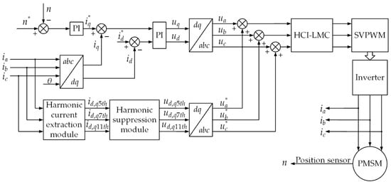
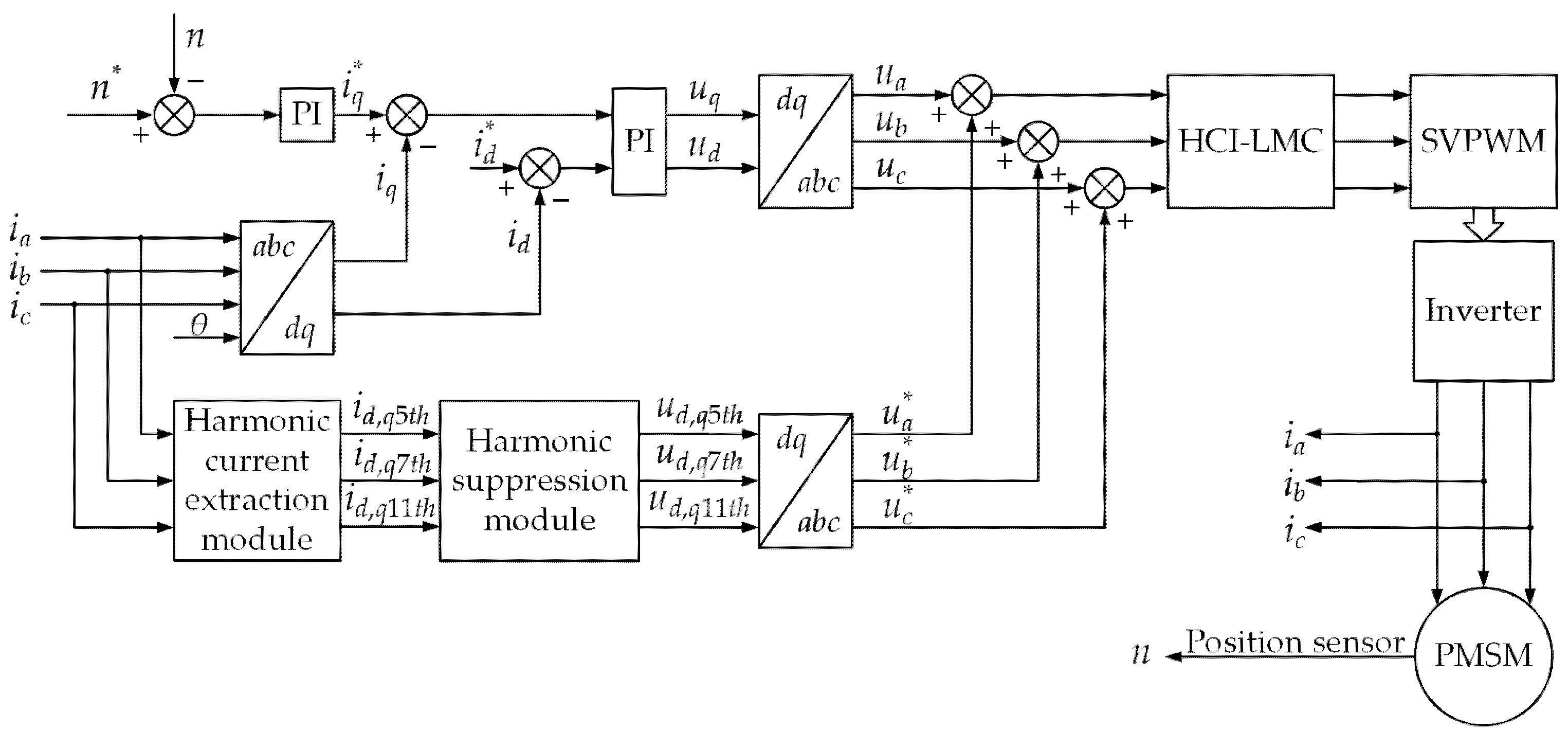
The overall control diagram for the efficiency optimization of the PMSM based on harmonic injection is shown in Figure 4. This control diagram first calculates the initial d-q axis control currents based on the minimum loss control model. After passing through the PI controller and coordinate transformation, the initial three-phase voltage is obtained. The harmonic extraction module then extracts the current harmonics from the three-phase current. After harmonic suppression and coordinate transformation, the compensation voltage is calculated. The initial voltage and compensation voltage are fed into the efficiency optimization module, where the theoretical current values calculated using Equation (15) are transformed to theoretical voltage values. The difference between the actual input voltage and the theoretical voltage is used for compensation. The final voltage is then output to the SVPWM module, which controls the PMSM through the inverter.
Figure 4.
The overall control block diagram for efficiency optimization of PMSM based on harmonic suppression.
This control strategy effectively reduces the harmonic losses in the PMSM, minimizes current waveform distortion, and controls the current so that the motor operates at the minimum loss point, thereby improving the motor’s operational efficiency.
4. Analysis of Simulation Results
4.1. Simulation Results of the Equivalent Circuit
To validate the effectiveness of the proposed harmonic injection-based efficiency optimization control method, a comparative simulation analysis was conducted. The dead-time effects of the inverter were incorporated to generate a realistic power supply current.
The main motor parameters and simulation settings are listed in Table 1 to improve reproducibility. All control strategies were evaluated using the same parameter set, solver configuration, and simulation step size.
Table 1.
Main motor parameters and simulation settings.
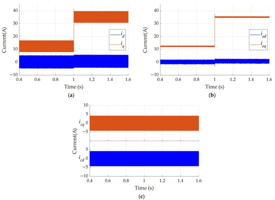
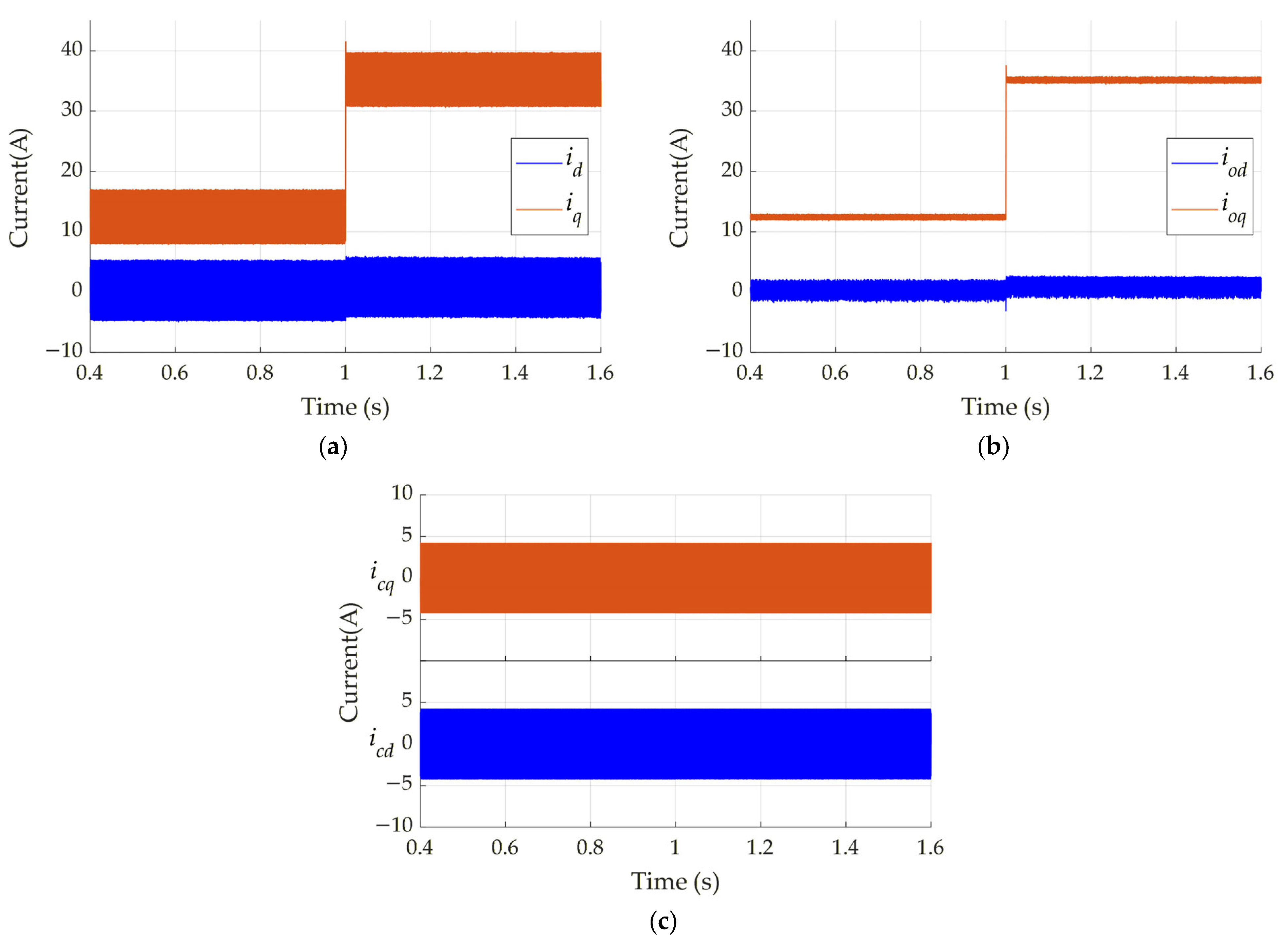
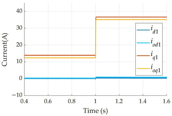
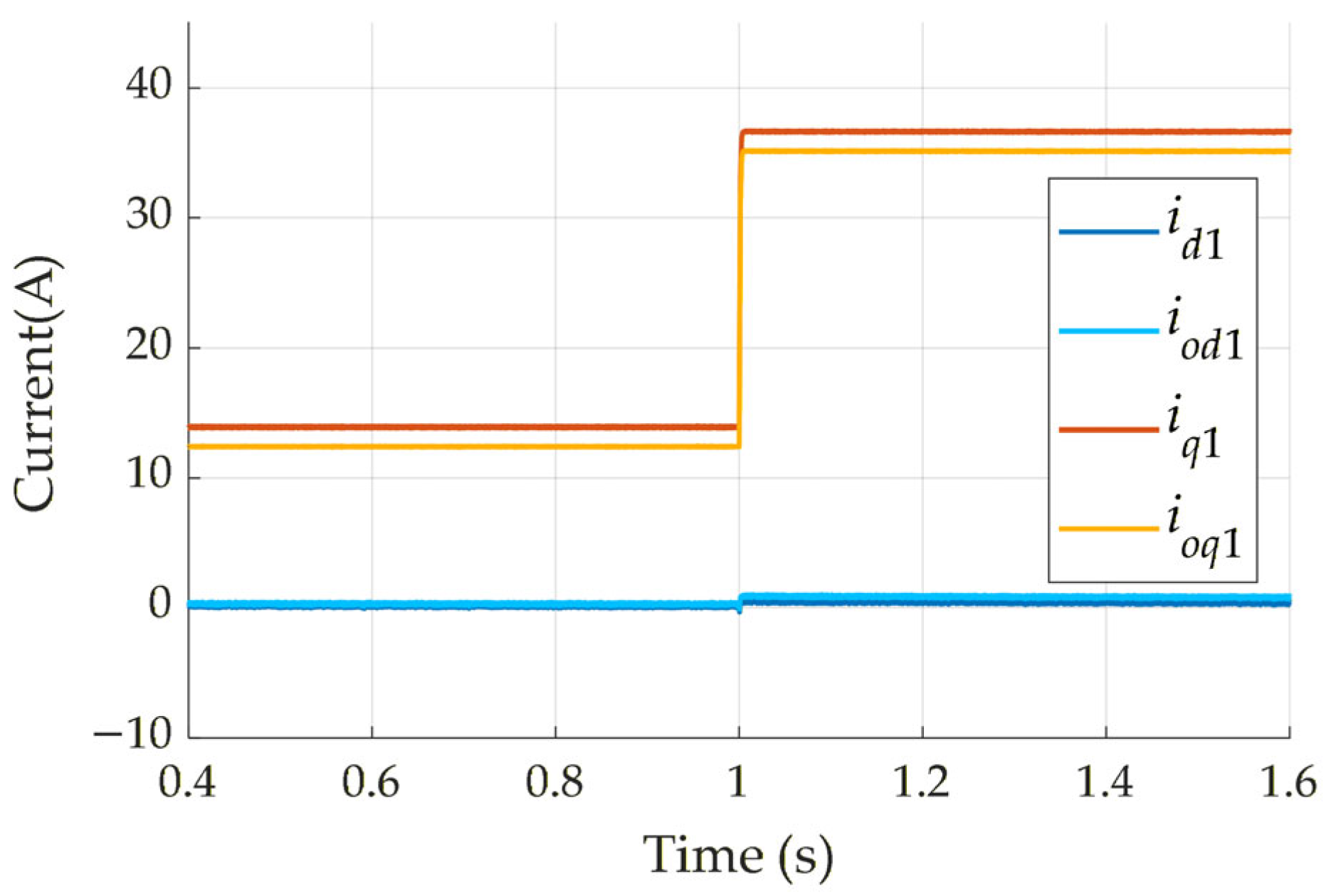
Figure 5 presents the current responses of the equivalent circuit model under a torque step condition. In the simulation, the load torque is abruptly increased from 10 to 30 at . Figure 5a–c corresponds to the dynamic responses of the dq-axis current, dq-axis torque current, and dq-axis iron-loss current, respectively. To enable a clearer comparison between the stator current and the torque current, the two current signals are filtered by a low-pass filter to extract their fundamental components. The resulting comparison of the fundamental current components is shown in Figure 6.
Figure 5.
Responses of different dq-axis current components: (a) dq-axis stator currents, (b) dq-axis torque currents, (c) dq-axis equivalent iron-loss currents.
Figure 6.
Comparison of the fundamental components of the stator current and torque current.
The simulation results show that the currents in the equivalent circuit model contain relatively rich harmonic components. These harmonic components have certain effects on the dynamic and steady-state performance of the motor control system.
4.2. Simulation Results of Harmonic Injection
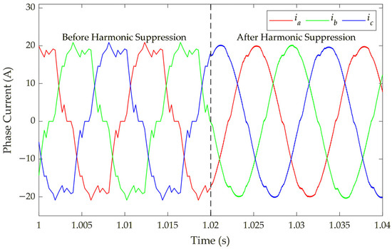
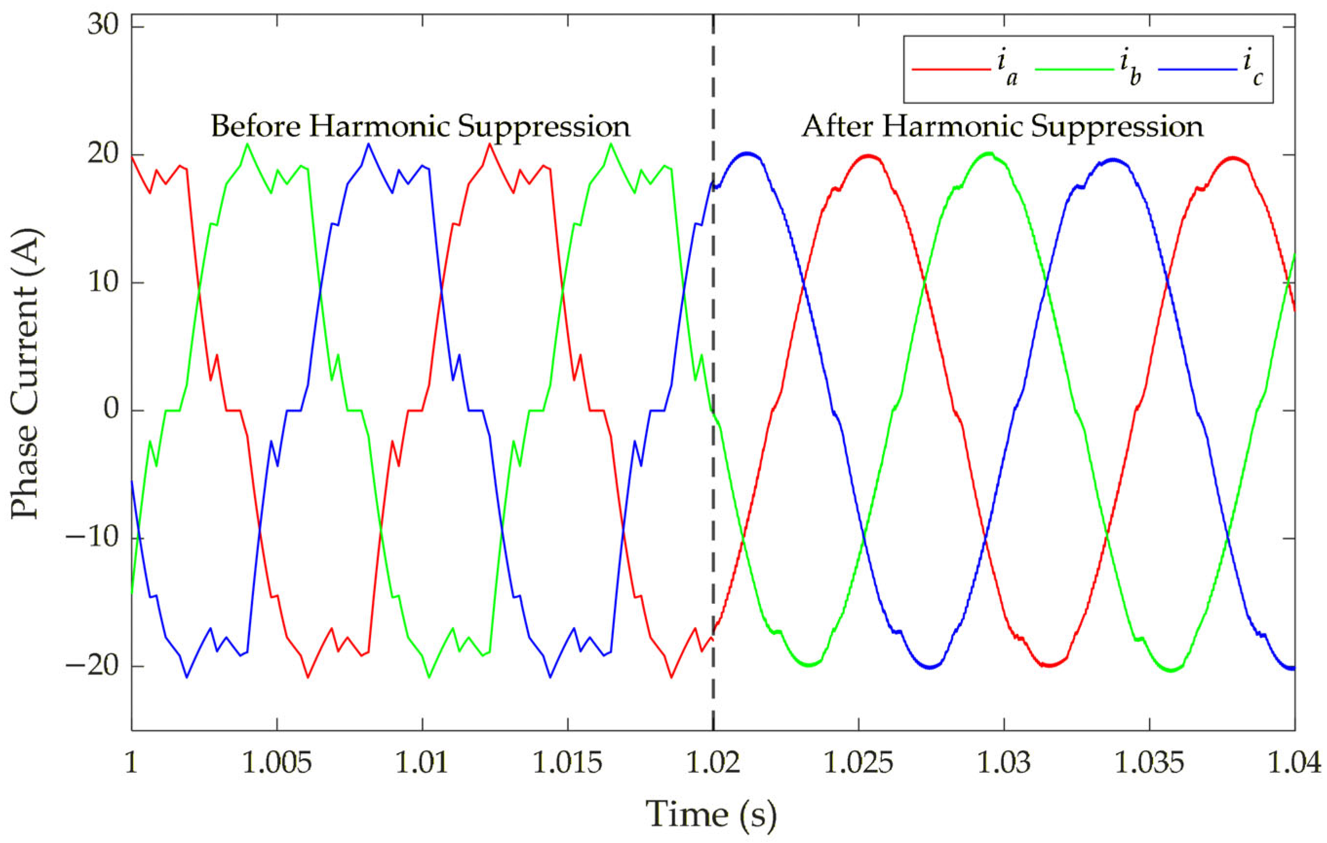
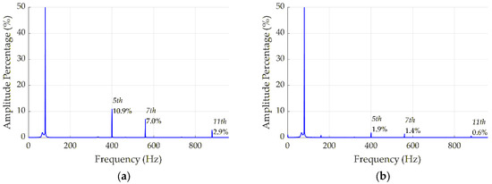
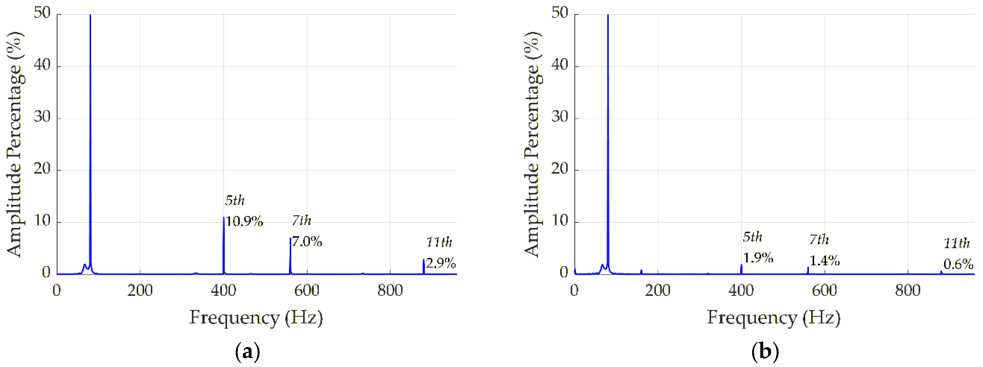
Figure 7 compares the stator current waveforms before and after harmonic suppression, demonstrating a substantial reduction in waveform distortion. To quantitatively evaluate this improvement, a Fast Fourier Transform (FFT) analysis was performed on the current signals, with the results presented in Figure 8. As demonstrated by the quantitative FFT analysis, the amplitudes of the 5th, 7th, and 11th harmonic currents are effectively suppressed. This confirms that the harmonic voltage injection strategy successfully mitigates the targeted harmonic components in the stator current.
Figure 7.
Comparison of three-phase current before and after harmonic suppression.
Figure 8.
Comparison of A-phase current spectrum analysis before and after harmonic suppression: (a) before harmonic suppression, (b) after harmonic suppression.
4.3. Comparison of Results Between the HCI-LMC and LMC Algorithms
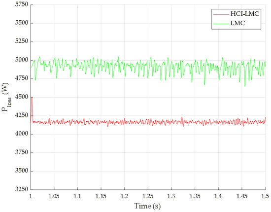
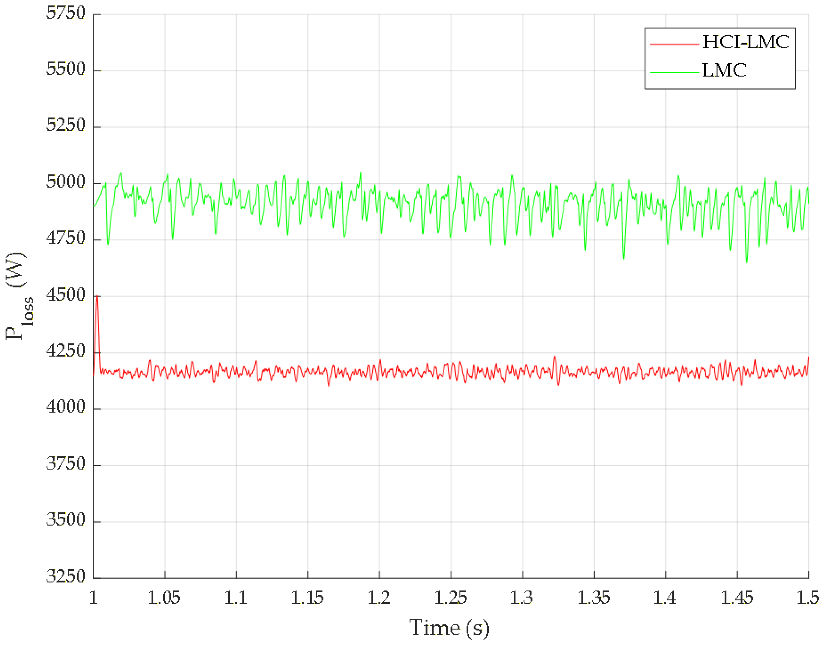
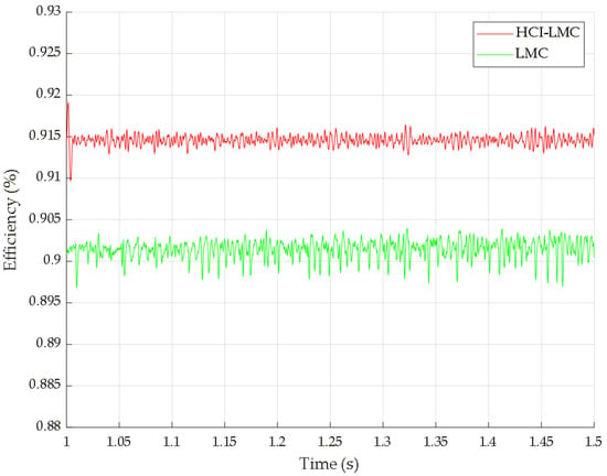
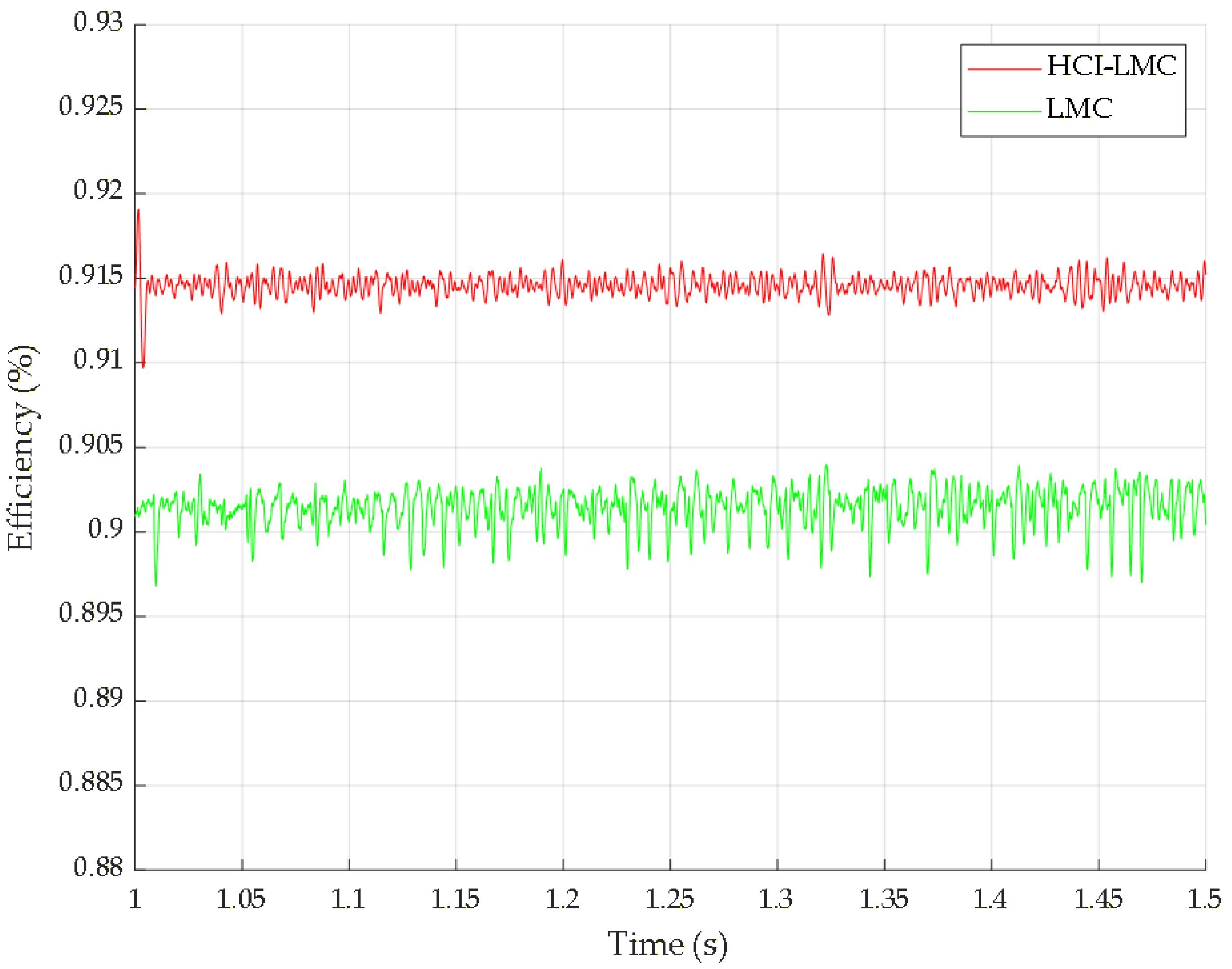
In addition, the total losses and efficiencies were calculated under the same simulation conditions, where the motor speed and load torque were set to 6300 r/min and 55, respectively. Figure 9 compares the calculated total losses under the LMC and HCI-LMC schemes, showing that the HCI-LMC scheme reduces the motor losses when current harmonics are considered. Figure 10 compares the corresponding calculated efficiencies, showing that the motor efficiency is improved compared with the LMC scheme.
where is motor efficiency, is motor input power.
Figure 9.
Total loss between LMC and HCI-LMC.
Figure 10.
Efficiency comparison between LMC and HCI-LMC.
The comparison indicates that the HCI-LMC scheme provides higher efficiency than the conventional LMC scheme. This difference is mainly related to the loss components considered in the two methods. The conventional LMC determines the current reference by considering copper and iron losses, whereas the proposed HCI-LMC method further includes harmonic-related losses in the loss model. By accounting for copper, iron, and harmonic loss components, the HCI-LMC scheme reduces the calculated motor losses, leading to an increase in the corresponding efficiency.
5. Conclusions
This study addresses the coordinated control problem of harmonic suppression and efficiency optimization in a permanent magnet synchronous motor by proposing the Harmonic-Current-Inclusive Loss Minimization Control method. The HCI-LMC method employs multiple synchronous reference frames to extract the 5th, 7th, and 11th harmonic components in real time, and then injects them into the comprehensive loss model. By integrating fundamental and harmonic losses into a unified optimization framework, the proposed method optimizes the allocation of all current components to minimize total losses. As a result, the stator current total harmonic distortion and torque ripple are significantly reduced, while the comprehensive operational efficiency of the motor is improved. Simulation results validate the effectiveness of the HCI-LMC strategy in achieving global efficiency optimization and superior harmonic suppression.
Author Contributions
Conceptualization, H.J., F.Y. and D.Q.; methodology, H.J., Z.Z. and F.Y.; software, Z.Z. and F.Y.; validation, H.J. and Z.Z.; formal analysis, F.Y.; investigation, H.J. and Z.Z.; resources, H.J.; data curation, Z.Z.; writing—original draft preparation, Z.Z. and F.Y.; writing—review and editing, H.J., D.L. and Z.Z.; visualization, Z.Z.; supervision, X.X.; project administration, H.J.; funding acquisition, H.J. All authors have read and agreed to the published version of the manuscript.
Funding
This research was funded by the National Natural Science Foundation of China (Grant No. 52305053), the Science and Technology Research Program of Chongqing Municipal Education Commission (Grant No. KJQN202100721), and the Open Foundation of State Key Laboratory of Mechanical Transmission for Advanced Equipment (Grant No. SKLMT-MSKFKT-202223).
Data Availability Statement
The datasets from this paper are accessible through the corresponding author upon reasonable request.
Acknowledgments
The authors would like to thank the handling editor and anonymous reviewers for their useful comments and constructive suggestions.
Conflicts of Interest
The authors declare no conflicts of interest.
References
- He, Q.; Wang, H.; Li, Q. Design Optimization and Performance Analysis of High Torque Density and Efficiency Motors for eVTOL Applications. IEEE Access 2025, 13, 78403–78415. [Google Scholar] [CrossRef] [Scilit]
- Serafini, J.; Cremaschini, M.; Bernardini, G.; Solero, L.; Ficuciello, C.; Gennaretti, M. Conceptual All-Electric Retrofit of Helicopters: Review, Technological Outlook, and a Sample Design. IEEE Trans. Transp. Electrif. 2019, 5, 782–794. [Google Scholar] [CrossRef] [Scilit]
- Liang, S.; Wu, X.; Wu, Z.; Liu, W. Progress and Challenges on Materials Used to Optimize Flight Efficiency, Improve Safety and Reliability, and Reduce Cost of Electric Vertical Take-off and Landing Aircraft. J. Appl. Polym. Sci. 2025, 142, e57029. [Google Scholar] [CrossRef] [Scilit]
- Morimoto, S.; Takeda, Y.; Hirasa, T.; Taniguchi, K. Expansion of Operating Limits for Permanent Magnet Motor by Current Vector Control Considering Inverter Capacity. IEEE Trans. Ind. Appl. 1990, 26, 866–871. [Google Scholar] [CrossRef] [Scilit]
- Pairo, H.; Shoulaie, A. Effective and Simplified Method in Maximum Efficiency Control of Interior Permanent Magnet Synchronous Motors. IET Electr. Power Appl. 2017, 11, 447–459. [Google Scholar] [CrossRef] [Scilit]
- Hang, J.; Wu, H.; Ding, S.; Huang, Y.; Hua, W. Improved Loss Minimization Control for IPMSM Using Equivalent Conversion Method. IEEE Trans. Power Electron. 2021, 36, 1931–1940. [Google Scholar] [CrossRef] [Scilit]
- Fan, W.; Zhu, X.; Xu, L.; Quan, L. Loss-Minimized-Model-Based Current-Decoupling Control for Interior Permanent Magnet Motor with Hybrid Rotor Poles. IEEE Trans. Transp. Electrif. 2025, 11, 4656–4666. [Google Scholar] [CrossRef] [Scilit]
- Wang, Q.; Zhang, G.; Wang, G.; Li, C.; Xu, D. Offline Parameter Self-Learning Method for General-Purpose PMSM Drives with Estimation Error Compensation. IEEE Trans. Power Electron. 2019, 34, 11103–11115. [Google Scholar] [CrossRef] [Scilit]
- Yu, K.; Wang, Z.; Wang, X.; Zou, Z. An Online Flux Estimation for Dual Three-Phase SPMSM Drives Using Position-Offset Injection. IEEE Trans. Power Electron. 2021, 36, 11606–11617. [Google Scholar] [CrossRef] [Scilit]
- Seyyedzadeh, S.M.; Shoulaie, A. Accurate Modeling of the Nonlinear Characteristic of a Voltage Source Inverter for Better Performance in near Zero Currents. IEEE Trans. Ind. Electron. 2019, 66, 71–78. [Google Scholar] [CrossRef] [Scilit]
- El-Daleel, M.S.; Mahgoub, O.; Elshafei, A.L.; Mahgoub, A. Inverter Dead-Time and Non-Linearity Rejection Using a Wide Bandwidth Current Controller for PMSM Drives with a Speed Sensor. In Proceedings of the 2016 Eighteenth International Middle East Power Systems Conference (MEPCON), Cairo, Egypt, 27–29 December 2016; IEEE: New York, NY, USA, 2016; pp. 687–692. [Google Scholar]
- Yu, K.; Wang, Z. An Online Compensation Method of VSI Nonlinearity for Dual Three-Phase PMSM Drives Using Current Injection. IEEE Trans. Power Electron. 2022, 37, 3769–3774. [Google Scholar] [CrossRef] [Scilit]
- Miyama, Y.; Hazeyama, M.; Hanioka, S.; Watanabe, N.; Daikoku, A.; Inoue, M. PWM Carrier Harmonic Iron Loss Reduction Technique of Permanent-Magnet Motors for Electric Vehicles. IEEE Trans. Ind. Appl. 2016, 52, 2865–2871. [Google Scholar] [CrossRef] [Scilit]
- Zhu, J.G.; Ramsden, V.S. Improved Formulations for Rotational Core Losses in Rotating Electrical Machines. IEEE Trans. Magn. 1998, 34, 2234–2242. [Google Scholar] [CrossRef] [Scilit]
- Yang, G.; Cui, Z.; Song, L. Analysis of Iron Losses in Induction Motor with an Improved Iron-Loss Model. In Proceedings of the 2014 IEEE Conference and Expo Transportation Electrification Asia-Pacific (ITEC Asia-Pacific), Beijing, China, 31 August–3 September 2014; IEEE: New York, NY, USA, 2014; pp. 1–4. [Google Scholar]
- Zhu, Z.Q.; Liu, Y. Analysis of Air-Gap Field Modulation and Magnetic Gearing Effect in Fractional-Slot Concentrated-Winding Permanent-Magnet Synchronous Machines. IEEE Trans. Ind. Electron. 2018, 65, 3688–3698. [Google Scholar] [CrossRef] [Scilit]
- Morimoto, S.; Sanada, M.; Takeda, Y. Wide-Speed Operation of Interior Permanent Magnet Synchronous Motors with High-Performance Current Regulator. IEEE Trans. Ind. Appl. 1994, 30, 921–926. [Google Scholar] [CrossRef] [Scilit]

Disclaimer/Publisher’s Note: The statements, opinions and data contained in all publications are solely those of the individual author(s) and contributor(s) and not of MDPI and/or the editor(s). MDPI and/or the editor(s) disclaim responsibility for any injury to people or property resulting from any ideas, methods, instructions or products referred to in the content. |
© 2026 by the authors. Licensee MDPI, Basel, Switzerland. This article is an open access article distributed under the terms and conditions of the Creative Commons Attribution (CC BY) license.