


Abstract
As a driving mechanism, the electromagnetic repulsion mechanism has been widely used in mechanical switches, such as circuit breakers, current limiters, and bypass switches, owing to its high closing speed and large output force. The dynamic characteristics and structural safety of electromagnetic repulsion mechanisms are critical to the stable and reliable operation of mechanical switches. However, the dynamic characteristics of electromagnetic repulsion mechanisms are affected by multiple factors, including coil parameters, energy storage parameters, armature structural dimensions, and air gaps. Moreover, strong coupling exists among these design variables. Parameter optimization that focuses solely on operating speed or electromagnetic force may lead to local stress concentration and edge vibration of the armature, thereby compromising the operational reliability of the mechanism. To address the difficulty in synergistically optimizing dynamic characteristics and structural safety, this paper proposes a two-stage optimization method that combines the series armature equivalent method, genetic algorithm-based multi-objective optimization, structural shape optimization, and topology optimization. In the first stage, a series armature equivalent model is established, and design parameters are optimized by the genetic algorithm to obtain a parameter combination that satisfies the requirements for displacement, closing speed, and operating time. In the second stage, under the constraints of dynamic performance, armature shape optimization, topology optimization, and combined shape–topology optimization are separately conducted to reduce edge vibration and local stress concentration of the armature. The dynamic characteristics, edge vibration displacement, and stress under different optimization schemes are comparatively analyzed. The results show that the proposed two-stage optimization method can effectively improve the structural response of the armature while ensuring that the dynamic characteristics of the mechanism satisfy the design requirements. In particular, after the combined optimization, the edge vibration of the armature is reduced to 41.8% of that before optimization, and the local stress concentration is significantly alleviated. The proposed optimization framework realizes the coordination between parameter design and armature structural optimization of electromagnetic repulsion mechanisms, providing a reference for improving the dynamic characteristics and structural reliability of electromagnetic repulsion mechanisms.
1. Introduction
The electromagnetic repulsion mechanism has been widely used in high-speed mechanical switches owing to its large output force and large peak electromagnetic force. In the design of electromagnetic repulsion mechanisms, both closing speed and structural safety are critical to the stable and reliable operation [1]. Generally, the dynamic characteristics of the electromagnetic repulsion mechanism, particularly the closing time, are considered first. Subsequently, the mechanical strength of the moving components should be evaluated to ensure that the mechanism maintains sufficient structural reliability during operation [2].
To improve the dynamic characteristics of electromagnetic repulsion mechanisms, researchers have carried out a lot of work on optimizing the dynamic characteristics of mechanisms, including modeling, calculation, and optimization. Lim et al. used analytical and numerical methods to conduct parameter analysis on the dynamic characteristics of electromagnetic repulsion mechanisms [3]. Tian Yang et al. proposed a multi-physics field coupling method involving electromagnetic field, temperature field, and motion field during the operation of a high-speed mechanical switch repulsion mechanism and pointed out that the number of turns of the coil is the key factor affecting the performance of various high-speed mechanical switches [4]. Guo Xingyu et al. studied the influence of temperature on the dynamic characteristics of the electromagnetic repulsion mechanism and pointed out that heat dissipation measures should be considered when designing coils [5]. Wen Weijie et al. calculated and summarized three key parameters affecting the dynamic characteristics of the electromagnetic repulsion mechanism and pointed out that stress verification should be carried out after parameter design [6]. Zhang Ning et al. analyzed the double coil type repulsion mechanism and found that as the number of coil turns, coil winding thickness, opening coil winding height, and motion coil winding height increase, the peak value of electromagnetic repulsion and 2 ms displacement show a trend of first increasing and then decreasing [7]. Wu Yifei et al. analyzed the influence of different shell materials on dynamic characteristics and pointed out that the electromagnetic repulsion peak value is the largest when steel material is used [8]. Ara Bissal et al. analyzed the factors affecting the operating efficiency of the electromagnetic repulsion mechanism and pointed out that in order to improve efficiency, the time of the electromagnetic force pulse should be shortened as much as possible [9]. In the current analysis and optimization of the dynamic characteristics of the mechanism, the closing time of the mechanism is mostly designed and analyzed by single-factor analysis. The multi-objective optimization method that comprehensively considers the closing speed and closing time of the mechanism still needs in-depth research.
The optimization of the dynamic characteristics of the electromagnetic repulsion mechanism increases the amplitude of the electromagnetic force and shortens the closing time. Therefore, the structural strength of the moving parts should also be considered to ensure their reliability during operation. Yang Fei et al. calculated the stress distribution of the moving contact and metal disk during the high-speed movement of the mechanism and pointed out that the influence of mechanical deformation on the dynamic characteristics should be considered during high-speed movement [10]. Hu Yang et al. used the flexible body theory and transient dynamics method to calculate the stress and strain distribution of the moving parts of the medium-voltage DC fast-operating mechanism [11]. Vilchis-Rodriguez compared the results of the dynamic characteristics of the electromagnetic repulsion mechanism obtained by 2D and 3D model calculations and pointed out that the calculation results are similar and relatively accurate at the dominant frequency, but the influence of edge deformation on the strength of the mechanism during the movement should still be considered [12]. Dong Runpeng et al. analyzed the vibration phenomenon during the opening process of the repulsion disk and found that the elastoplastic deformation caused by the uneven distribution of Lorentz force is the main reason for the vibration or bending of the repulsion disk [13]. Zhu et al. analyzed the stress distribution of the repulsion disk during the movement of the electromagnetic repulsion mechanism and analyzed the design of geometric parameters to improve stress concentration [14,15]. Guan et al. established a fully coupled simulation model of the superconducting fault current limiter. Through simulation, they found that the stress concentration location was the same as the location of multiple failures, which verified the accuracy of the proposed simulation model [16]. Therefore, the structural strength design of moving parts should also be taken into account when designing the mechanism, and edge vibration and stress concentration should be avoided as much as possible.
Optimizing the dynamic characteristics of the electromagnetic repulsion mechanism requires establishing digital models and multiple calculations, which is limited by computational efficiency. Structural design and optimization often focus on traditional parameter optimization of the moving parts of the mechanism, namely the armature. This typically relies on adjusting a small number of preset geometric parameters (such as armature outer diameter and thickness). It cannot overcome the limitations of the initial topology and is difficult to optimize aspects such as material additions or subtractions, changes in structural connectivity, or local structural reconstruction. Furthermore, parameter optimization struggles to describe irregular structures or material distribution characteristics, especially given the strong electromagnetic–structural coupling effect in electromagnetic repulsion mechanisms. Simply adjusting parameters is insufficient to significantly improve problems such as excessive armature edge vibration amplitude and local stress concentration. Therefore, it is necessary to comprehensively consider both the dynamic characteristics and structural strength of the electromagnetic repulsion mechanism. Currently, few optimization methods simultaneously consider both aspects, and further research is needed in this area to ensure the structural safety of the mechanism during high-speed operation.
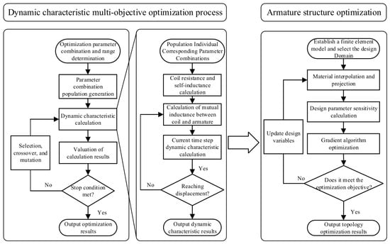
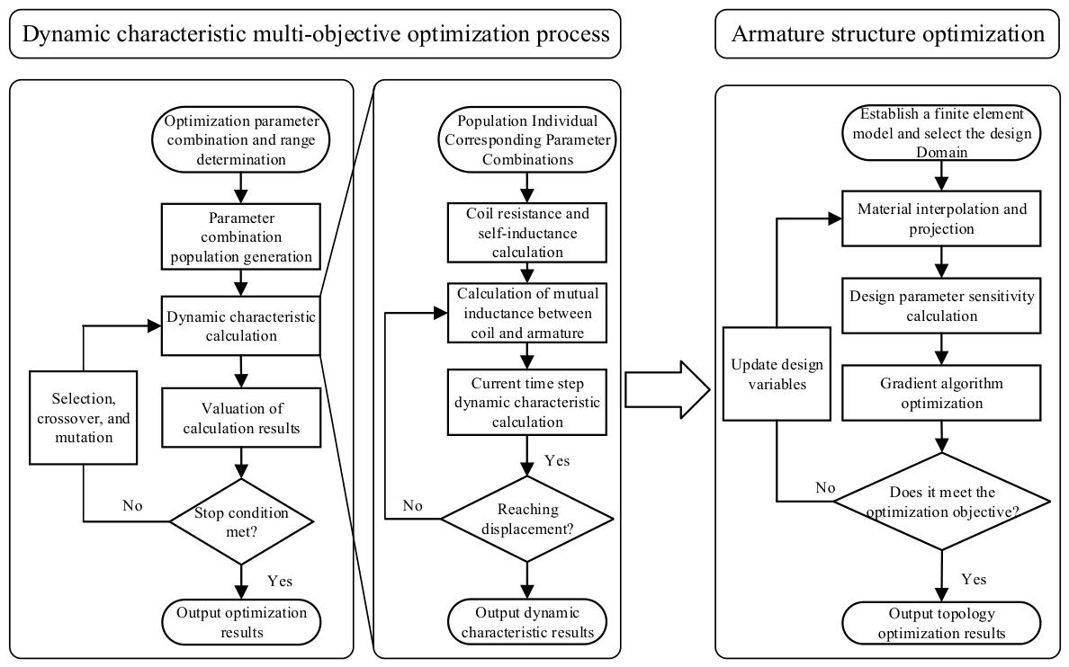
To address the challenge of co-optimizing the dynamic characteristics and structural safety of the electromagnetic repulsion mechanism, this paper proposes a two-stage optimization method combining the series armature equivalent method, multi-objective optimization using a genetic algorithm, structural shape optimization, and topology optimization; the optimization method flow is shown in Figure 1. The first stage employs a genetic algorithm to perform multi-objective optimization of the dynamic characteristics, obtaining parameter combinations that satisfy the displacement, closing time, and closing speed. Building upon this, the second stage, constrained by the dynamic characteristics, utilizes shape optimization, topology optimization, and a combined shape–topology optimization method. Shape optimization selects the design domain for topology optimization and optimizes the geometry of the moving parts to mitigate edge vibration and stress concentration under electromagnetic force. Results show that the proposed method effectively reduces stress amplitude and edge vibration during operation, thereby improving the mechanical dynamic characteristics and operational reliability. This provides a structural optimization method for moving parts of the electromagnetic repulsion mechanism, offering a theoretical basis and technical reference for improvement and engineering design of related devices.
Figure 1.
Schematic diagram of collaborative optimization of dynamic characteristics and armature structure.
2. Principle of the Electromagnetic Repulsion Mechanism
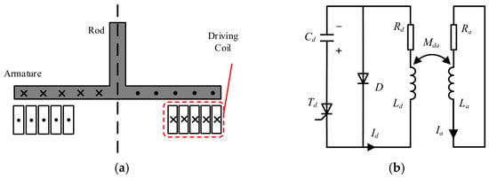
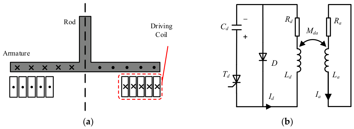
The electromagnetic repulsion mechanism consists of two parts: the mechanism body and the drive circuit, as shown in Figure 2.
Figure 2.
Schematic diagram of electromagnetic repulsion mechanism. (a) Structure diagram; (b) equivalent circuit diagram.
The main components of the electromagnetic repulsion mechanism include a coil, an armature, and a connecting rod. The driving circuit includes a pre-charge capacitor Cd, a thyristor Td, a freewheeling diode D, and a driving coil. The resistance and inductance of the driving circuit are Rd and Ld, respectively.
The electromagnetic repulsion mechanism operates through the eddy current effect induced between the driving coil and the armature. When the mechanism is not driven, Td is turned off, and the pre-charge voltage of the capacitor remains unchanged. After driving, Td turns on, and the capacitor discharges to the driving coil, generating a pulse current Id. Id excites a time-varying magnetic field in space, where the axial component of the magnetic induction intensity generates eddy currents in the armature, and the radial component interacts with the eddy currents to generate an electromagnetic force, thereby driving the armature to move away from the driving coil.
Electromagnetic force can be obtained from the magnetic field energy. Considering the armature as an equivalent coil, the current in it is Ia, the resistance is Ra, the inductance is La, and the mutual inductance between the equivalent coil and the driving coil is Mda. The total energy of the magnetic field in the mechanism after the capacitor discharges is
The electromagnetic force is obtained by differentiating the total magnetic energy with respect to displacement. Since the geometries of the driving coil and the armature are fixed, their self-inductances remain constant, and the corresponding derivative terms are zero. Therefore, the electromagnetic force is:
The dynamic characteristic parameters, including the acceleration, velocity, and displacement of moving parts, can be calculated by the electromagnetic force:
where a is acceleration, v is velocity, x is displacement, and v0 and x0 are the initial values of velocity and displacement, which are both 0 in the calculation. Fh is the holding force, and m0 is the mass of the moving parts. In the multi-objective optimization process, the dynamic characteristics of the mechanism are calculated by the series armature equivalent method [17].
3. Multi-Objective Optimization of Dynamic Characteristics
Common multi-objective optimization methods can generally be classified into two categories. The first category decomposes a multi-objective optimization problem into several single-objective optimization problems by selecting objective-related design parameters based on the designer’s experience. However, this approach may cause the optimization to become trapped in local optima. The second category employs multi-objective optimization algorithms to search for optimal solutions and construct a Pareto front. Compared with the former approach, the Pareto front provides a set of trade-off solutions that simultaneously consider multiple optimization objectives, allowing feasible solutions to be selected according to practical requirements. Therefore, multi-objective optimization is more suitable for the electromagnetic repulsion mechanism optimization.
3.1. Multi-Objective Optimization Constraints
In previous research results, it was found that the parameters that have the greatest impact on the dynamic characteristics of the electromagnetic repulsion mechanism are the inner radius of the driving coil, the capacitance, the capacitor charging voltage, and the gap between the coil and the armature [18]. Therefore, the above four parameters and the coil turn were selected as optimization parameters, because the coil turn will also directly affect the outer radius of the driving coil. The closing time and closing speed of the electromagnetic repulsion mechanism are used as optimization targets. The closing time, closing speed, and initial energy storage of the capacitor are used as constraints to realize the dynamic characteristic optimization design.
Multi-Objective Optimization: How do you pick the best design? You can try changing one thing at a time, but—especially here—it’s a dead end. This approach often gets stuck in “local” solutions that don’t really solve the whole problem. The better bet is to use a proper multi-objective optimization algorithm that can juggle everything at once and search for balanced solutions. The result? You get a “Pareto front”—basically, a menu of the best trade-off choices—rather than a single, compromised answer. First, the main variables they focus on: the inner radius of the driving coil, the size of the capacitor, the charge voltage, the gap between the coil and the armature, and the number of turns in the coil. These all play a huge role in how the mechanism performs. The actual targets are closing time and closing speed, but initial energy and reducing contact bounce matter too. Based on these factors, the number of coil turns is selected. The final constraints are as follows:
- Capacitor: 1 to 10 mF;
- Charging voltage: 400 to 1300 V;
- Coil–armature gap: 1 to 3 mm;
- Coil inner radius: 20 to 50 mm;
- Coil turns: 10 to 30.
The overall performance constraints of the mechanism are as follows:
- Closing time: up to 2.5 ms;
- Closing speed: up to 4 m/s;
- Initial capacitor energy: no more than 3000 J.
To solve the multi-objective optimization problem of the dynamic characteristics of the electromagnetic repulsion mechanism, this paper employs a multi-objective genetic optimization algorithm. The basic idea of the genetic algorithm is to randomly generate an initial population within the range of design variable values, with each individual in the population considered as a set of design parameters. The genetic algorithm starts by throwing together a random batch of designs, then checks each one for performance, sorts them, and hands out “survival points.” Through repeated selection, crossover, and mutation (the usual tricks in evolution-inspired searches), it gradually narrows in on the best combos—balancing all targets at once. In the end, you get a shortlist of top-performing designs that check all the boxes, ready for further refinement in the next stage.
3.2. Multi-Objective Optimization Results and Analysis
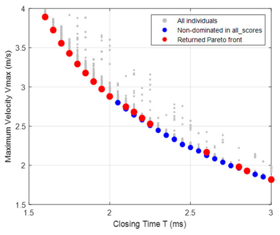
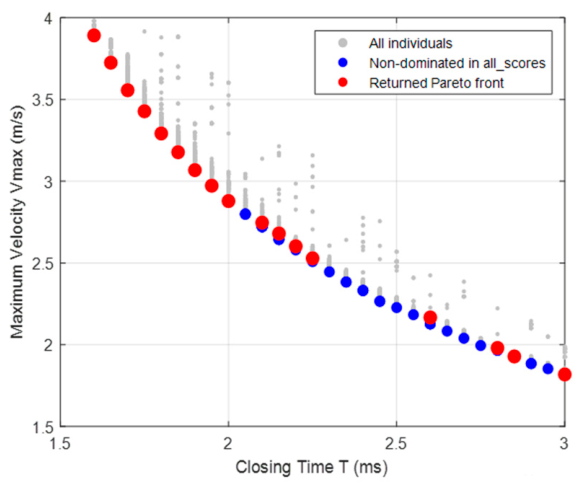
In this paper, the initial population size of the multi-objective genetic algorithm was set to 50, and the maximum number of generations was set to 100. The optimization results are shown in Figure 3. The gray dots represent all individuals in the 100th-generation population, the blue dots represent the non-dominated solutions extracted from all candidate individuals based on the non-dominated relationship, and the red dots represent the Pareto solution set that meets the constraints calculated by the optimization. In Figure 3, the maximum closing speed generally increases as the closing time gradually decreases. If the focus is on rapid closing, the result on the upper left side of the Pareto front should be selected; if the focus is on reducing bounce, the result on the lower right side should be selected.
Figure 3.
Multi-objective optimization result diagram.
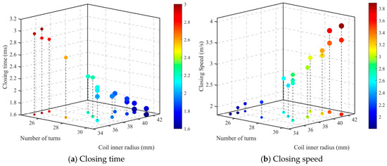
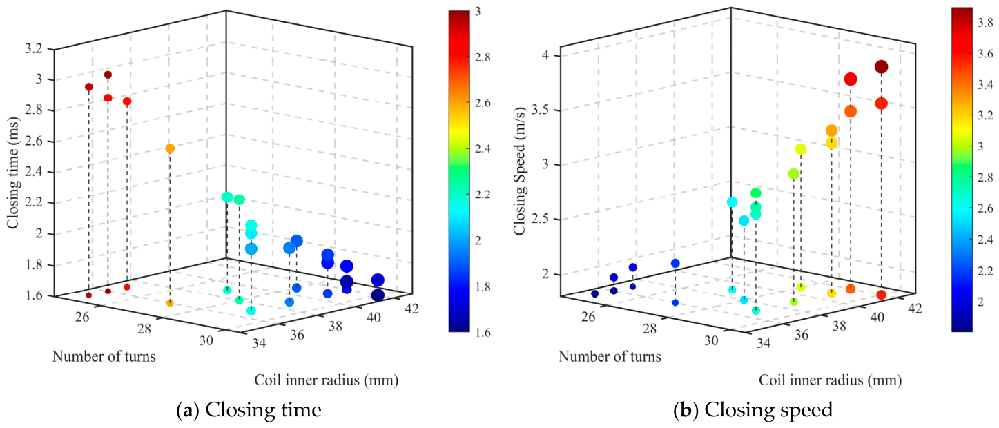
To further reveal the influence of key parameters on the dynamic characteristics of the mechanism, the solution in the Pareto front is further analyzed. Since the gap between the driving coil and armature varies within a small range, the inner radius of the driving coil and the number of coil turns are selected as analysis parameters to further analyze the influence of the two parameters on the closing time and closing speed. The corresponding results are in Figure 4.
Figure 4.
Pareto solution set scatter plot.
Considering the design requirements of rapid closing and reduced bounce, three parameter combinations located on the right side of the bottom projection in Figure 4 were selected for finite element simulation of the mechanism. The optimized parameter combinations and dynamic characteristic calculation results are shown in Table 1.
Table 1.
Optimization parameter combinations and calculation results.
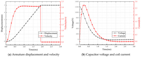
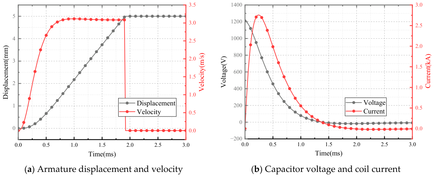
When the Pareto front contains many non-dominated solutions, post-processing of the Pareto solution set is usually required to reduce the complexity of subsequent analysis and decision-making. Existing studies often employ methods such as cluster analysis [19], representative solution extraction [20], and within-group design variable statistics [21] to summarize and characterize similar solutions within the Pareto solution set. In Table 1, all three parameter combinations meet the design requirements, and the parameters are very similar, indicating that the optimization results have good concentration and stability in this region and can be considered locally similar solution sets. Therefore, these three parameter combinations are averaged to construct a representative parameter combination. It should be noted that this parameter combination is not considered a new strictly Pareto-optimal solution, but rather a representative set extracted from similar Pareto solutions and used for subsequent dynamic characteristics and structural optimization. The final determined parameter combination is [1.5 mF, 1210 V, 29, 41 mm, 1.5 mm]. A finite element model was established to verify this parameter combination, and the dynamic characteristics calculated according to this combination are shown in Figure 5.
Figure 5.
Calculation of dynamic characteristics of final parameter combination.
The final parameter combination corresponds to a closing time of approximately 1.8 ms and a closing speed of 3 m/s, which meets the design requirements. This multi-objective optimization method can obtain parameter combinations that meet the design requirements and constraints, providing a reference for the design and optimization of electromagnetic repulsion mechanisms.
4. Optimization of the Moving Part Structure
After determining the design parameters of the electromagnetic repulsion mechanism, the corresponding mechanism will generate a short-duration, high-amplitude electromagnetic force when it operates. It will have a strong impact on the moving parts in a short time, which may lead to armature deformation or even damage. Therefore, without affecting the dynamic characteristics, analyzing the stress distribution during the operation of the mechanism and optimizing the impact-resistant structure of the moving parts to reduce the armature edge vibration and excessive local stress is of great significance to the reliability of the mechanism.
Structural optimization methods are mainly divided into three categories: size optimization, shape optimization, and topology optimization [22]. Size optimization is the most basic optimization method, which mainly improves performance without changing the overall structure by adjusting geometric parameters, such as length, thickness, and cross-sectional area. Shape optimization can adjust the structural boundary and optimize performance while keeping the topology unchanged [23]. Compared with size optimization, shape optimization has a larger design space, but still depends on the initial structural form. Topology optimization can automatically allocate materials in the design area to obtain the best performance. Its purpose is to reduce the designer’s dependence on the initial structure and realize the automated design and quantitative optimization of optimization parameters [24]. Compared with traditional methods, topology optimization has a higher degree of design freedom and a stronger global optimization capability in structural design [25].
4.1. Equivalent Static Load Method
To optimize the armature structure by topology optimization, the electromagnetic force acting on the armature needs to be converted into an equivalent static load, thereby improving the feasibility. The equivalent static load method, based on certain parameters, ensures that the response produced by the static load applied to the structure is the same as that produced by the dynamic load, thus determining the calculation method for the corresponding static load. For the electromagnetic repulsion mechanism, the relationship between the pulse force duration and the armature’s natural period should be considered to determine whether the dynamic effect is significant. Based on this, an equivalent static load model suitable for topology optimization can be established.
Structural dynamics reveals a strong relationship between load duration and the structure’s natural period. To determine the impact of the electromagnetic repulsion mechanism’s dynamic effects, it is necessary to calculate the ratio η of the load duration to the structure’s natural period. η is the ratio of the pulse force duration τ to the natural period T of the armature-dominant mode.
η = τ/T,
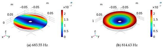
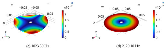
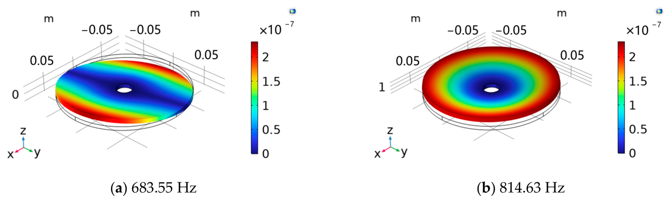
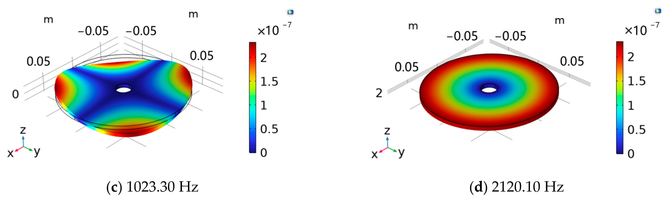
Parameter η indicates the relationship between the load and the structural response. Generally, when η ≫ 1, the dynamic effect is weak, and the problem can be considered quasi-static; when η = 0.25–2, the dynamic effect should not be ignored; and when η ≪ 1, the problem should be considered an impact problem, and peak static load cannot be a substitute. Based on the parameter combination obtained from the multi-objective optimization above, an armature geometric model is established, and the natural frequencies are calculated to obtain the natural period. An armature made of T6061 aluminum alloy with a thickness of 5 mm, an outer diameter of 160 mm, and an inner diameter of 20 mm was modeled, and modal analysis was performed using the solid mechanics module in COMSOL 6.2 software. Figure 6 shows the natural frequencies and corresponding mode shapes.
Figure 6.
Armature natural frequencies and modes.
Since the electromagnetic force on the armature in the electromagnetic repulsion mechanism is mainly distributed axially in the region overlapping with the driving coil, and the load is approximately symmetrical in the circumferential direction, the axisymmetric bending mode that matches the spatial distribution characteristics of the load is selected as the dominant mode from the various vibration modes, and the natural period of the structure is determined accordingly. According to the modal analysis results, the natural frequency of the axisymmetric dominant vibration mode corresponding to the armature is 814.63 Hz, and its natural period is 1.23 ms.
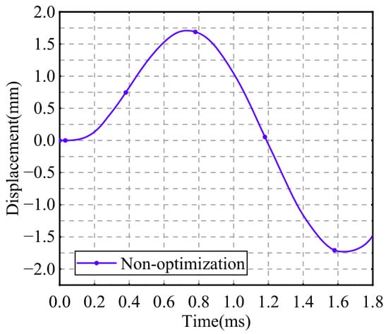
Based on the design parameters of the electromagnetic repulsion mechanism, the dynamic characteristics can be calculated. The peak value of the electromagnetic force is approximately 17 kN, while its duration is about 0.24 ms; therefore, the influence of dynamic effects cannot be ignored. To find an equivalent static load suitable for topology optimization, this paper selects the armature edge vibration displacement as the equivalence criterion for the response. First, transient analysis is performed under the action of the electromagnetic force to calculate the maximum edge displacement of the armature during motion. Then, the electromagnetic force distribution at the peak moment is taken as the basic static load, and its amplitude is adjusted so that the edge displacement obtained from the static analysis is consistent with the maximum edge displacement under the transient analysis. The corresponding static load is defined as the equivalent static load of the electromagnetic force.
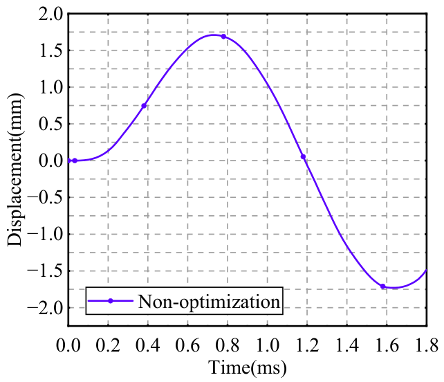
The armature edge vibration displacement is shown in Figure 7. The armature edge vibration displacement reaches the maximum value of 1.77 mm when the armature moves for 0.72 ms. The calculated force required to achieve the same displacement under static load is 7.4 kN. Therefore, subsequent optimization analysis is performed with a static load of 7.4 kN.
Figure 7.
Edge vibration displacement of the non-optimization armature.
It should be noted that the equivalent static load is determined based on the armature edge vibration displacement. The purpose is to provide an equivalent input for optimizing the total elastic strain energy of the armature, thereby improving the overall structural stiffness and reducing edge vibration displacement. It is not a complete equivalent of the transient process of the electromagnetic repulsion mechanism. Therefore, after the armature structure optimization, if further evaluation of the armature local stress distribution and the armature edge vibration displacement is required, dynamic characteristic calculations should still be performed for verification.
4.2. Armature Structure Topology Optimization Problem Description
Since topology optimization based on static analysis is required, and total elastic strain energy can directly characterize the overall stiffness of the structure, this paper selects the total elastic strain energy of the armature as the equivalent criterion.
Topology optimization consists of a design domain, design materials, objective equations, and constraints, which will be explained in detail below.
- Design Domain
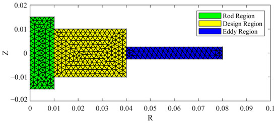
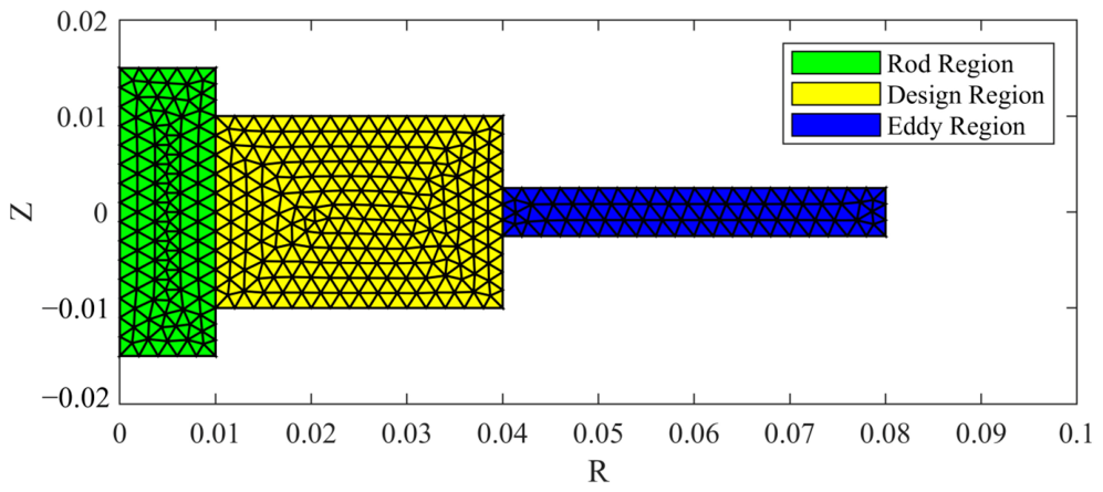
Topology optimization requires setting a design domain, which defines the optimization range required for that region as shown in Figure 8. Topology optimization is essentially a finite element calculation process, so the model needs to be meshed. Each finite element mesh element within the design region is used as a design variable for topology optimization, while the finite element elements outside the design region are used as regular elements and calculated by the governing equations. In the armature structure optimization problem, since the part that does not coincide with the coil in the axial vertical direction has almost no effect on the electromagnetic force amplitude, the region between the coil and the connecting rod is selected as the optimization design domain [26].
Figure 8.
Topology optimization design domain.
- 2.
- Design Material
The design material is determined by the topology optimization. For single-material topology optimization, the materials in the design domain are generally air and the design material, with one variable. However, for multi-material topology optimization, there are two or more design variables. This paper introduces a relative density variable ρ(x) ∈ [0, 1] in the design domain, where ρ = 1 indicates that the material is solid, and ρ ≈ 0 indicates that the material is empty. To establish the response between the material and the optimization objective, the SIMP interpolation method is used to interpolate the material’s elastic modulus. The interpolation expression is:
In the formula, E0 is the Young’s modulus of the T6061 alloy in the armature, Emin is a minimum value representing the lower limit of the Young’s modulus range, and p is a penalty factor, usually chosen as 3. Using the above interpolation method, a stiffness matrix related to the design variables can be constructed, thereby finding the optimal material distribution.
- 3.
- Objective Function
The objective function is determined by the final design goal. In armature structure optimization, the chosen objective is to minimize the total elastic strain energy, thereby minimizing the deformation at the armature edge and stress concentration. Under the given external load, the armature structure should satisfy the linear elastic static equilibrium equations:
where K(ρ) is the stiffness matrix related to the material distribution, U is the nodal displacement vector, and F is the load vector, used to characterize the external load applied to the armature. This paper uses the total elastic strain energy as the optimization objective, and its finite element form is:
The objective function reflects the total elastic strain energy stored in the structure under external loads. Under fixed load conditions, minimizing the total elastic strain energy is equivalent to increasing the overall stiffness of the structure.
- 4.
- Constraint
Constraints significantly influence the structural evolution during topology optimization. The fundamental constraint in the optimization is the volume fraction constraint of material density:
where Ve is the volume of the e-th element, V0 is the total volume of the design domain, and fv ∈ (0, 1) is the preset volume fraction. The proportion of the material in the design domain cannot exceed fv.
In summary, an armature topology optimization model is established by the density method. The material distribution within the design domain is the optimization object. The minimum total elastic strain energy of the armature is the optimization objective. The mathematical expression for the topology optimization can be summarized as follows:
4.3. Calculation of the Objective Function Sensitivity
Sensitivity calculation of the objective function is a crucial component of topology optimization, as the sensitivity with respect to design variables determines the optimization search state. Two commonly used sensitivity methods are the finite difference method and the adjoint variable method. The finite difference method applies small perturbations to the design variables and repeatedly solves the state equation, using the change in the objective function to calculate an approximate gradient. Its calculation process is relatively intuitive, but the computational cost is high when there are many design variables. The adjoint variable method, on the other hand, constructs a Lagrangian function to eliminate the derivative terms of the state variables with respect to the design variables, thus obtaining the sensitivity of the objective function with respect to the design variables. Since the design domain in topology optimization typically contains a large number of finite elements and numerous optimization variables, the adjoint variable method is more advantageous in such problems; therefore, it is chosen to calculate the sensitivity.
To facilitate derivation, the static equations are rewritten in residual form:
Constructing the Lagrange function using the residual form and the objective function
Differentiating the design variable ρ and combining like terms yields the following result:
In Equation (12), the adjoint variable λ is not an original physical unknown, but an auxiliary variable introduced to eliminate the derivative terms of the state variables in the sensitivity expression. Therefore, by satisfying a specific adjoint equation, the terms related to dU/dρ in the total derivative of the objective function can be made zero. This can be achieved by setting λ to satisfy a specific adjoint equation:
Since R = 0, L = J. Therefore, the sensitivity equation and the adjoint equation are obtained:
The adjoint variables can be obtained from the adjoint equation:
The partial derivative of J with respect to ρ is
Substitute the adjoint variable, partial derivative term, and R into the sensitivity equation:
The sensitivity of the objective function can be obtained by the above methods, allowing gradient-based algorithms to solve the minimization problem. In this paper, the Method of Moving Asymptotes (MMA) is applied. The overall optimization process includes FEA modeling, material interpolation, and design domain selection, as well as establishing the objective function and corresponding constraints. The adjoint method is then used to calculate the sensitivity. After obtaining the sensitivity, the model is iteratively optimized until convergence is met.
5. Comparison and Discussion of Optimization Results
The armature structure was optimized using topology optimization, shape optimization, and a combined shape–topology optimization method. The goal of the optimization was to reduce stress concentration and excessive deformation at the armature edges, thereby improving the reliability of the armature structure.
5.1. Structural Optimization Result
The results after shape optimization, topology optimization, and combined shape–topology optimization are shown in Figure 9. The topology optimization result has a small overall change to the outer contour of the design domain, and generates two cavities inside, thereby improving the stress performance of the armature by changing the material distribution; the shape optimization makes the geometric transition of the outer contour smoother while maintaining the overall solid connection; the combined optimization result has both of the above characteristics, maintaining the smooth outer contour of the structure while achieving a reasonable distribution of internal materials.
Figure 9.
Armature structure optimization axisymmetric schematic diagram.
5.2. Armature Edge Vibration Displacement
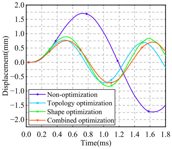
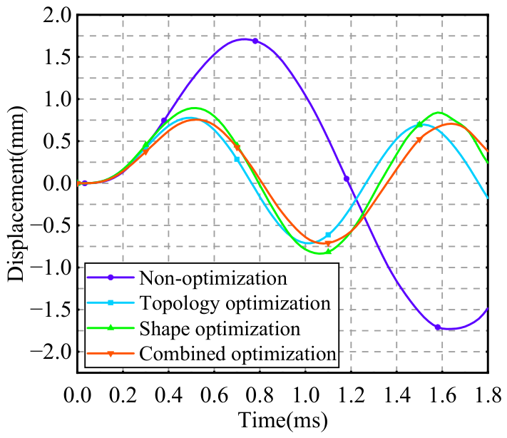
Dynamic characteristics analysis was performed on the optimized armature, and armature edge vibration displacement curves with different geometries were calculated under the same conditions. These curves were obtained by subtracting the armature center displacement from the armature edge displacement. The calculation results are shown in Figure 10, which plots the armature edge vibration displacements under four different armature structures. The effectiveness of each optimization method in suppressing edge vibration and improving structural stiffness was evaluated based on the calculation results.
Figure 10.
Calculation results of four optimized structures.
In Figure 10, all armature structures exhibit edge vibration under the electromagnetic force. Without optimization, the armature structure exhibits the largest edge vibration displacement and the latest peak value, indicating relatively insufficient overall stiffness under load. In contrast, the edge vibration displacements of the topology-optimized, shape-optimized, and jointly optimized structures are all reduced, demonstrating that both shape and topology optimization are effective in improving edge vibration displacement. Among the three optimization methods, the jointly optimized armature edge vibration displacement amplitude is the smallest, with a peak displacement of 0.74 mm, only 41.8% of the amplitude of the edge vibration displacement before optimization.
5.3. Armature Stress Distribution
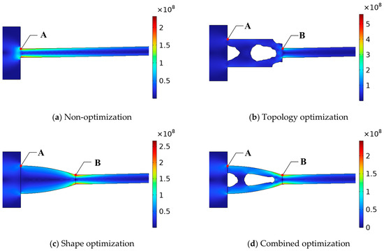
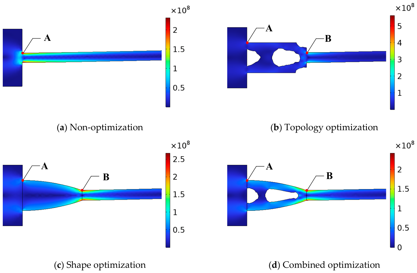
To evaluate the effectiveness of the optimization results from the perspective of local stress, it is also necessary to analyze the stress distribution during the armature motion process. The stress distribution of the armature at different times was calculated using the electromagnetic field, solid mechanics, and circuit modules of the COMSOL software. Figure 11 shows the stress distribution of the four armature structures at t = 0.5 ms.
Figure 11.
Armature stress distribution at 0.5 ms.
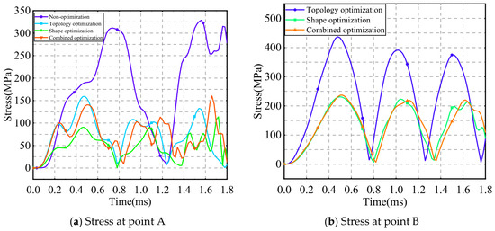
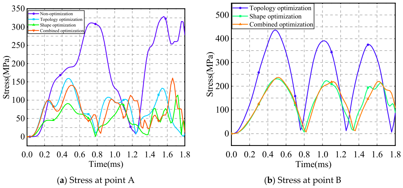
As shown in Figure 11, in the unoptimized structure, the stress concentration point is the right-angle region where the connecting rod and armature intersect, i.e., point A, coordinates [10 mm, 2.5 mm], in Figure 11a. In the three optimized structures, the stress concentration points are the connection between the design area and the connecting rod, and the connection between the armature and the coil in the vertical region, i.e., points A, coordinates [10 mm, 10 mm], and B, coordinates [40 mm, 2.5 mm], in Figure 11b–d. Therefore, these two points are selected to plot the stress-time curve, while for the unoptimized structure, only the connection point between the connecting rod and armature is selected. The stress curves are shown in Figure 12.
Figure 12.
Armature stress curves.
In Figure 12, the stress amplitude at point A of the three optimized structures is significantly lower than that of the unoptimized structure, with the shape-optimized structure exhibiting the smallest stress amplitude. This indicates that all three optimization methods effectively improve the local stress state in the armature center region. Among the three optimization methods, the stress at point A resulting from shape optimization is generally around 100 MPa, with a relatively gentle trend, suggesting its superior ability to improve the structural transition region and reduce sudden local stress changes. The stress at point A resulting from topology optimization is higher, approximately 160 MPa, indicating that the stress on the connection part with the link is enhanced after the material is redistributed within the design domain. The stress at point A resulting from combined optimization is slightly lower than that from topology optimization, suggesting that combining shape optimization can mitigate the stress concentration phenomenon caused by topology optimization to some extent.
The stress at point B, determined by topology optimization, is significantly higher than that obtained through shape optimization and combined optimization. The reason is that topology optimization does not alter the overall contour of the design domain, while shape optimization effectively improves the connection between the design region and the region perpendicular to the coil, making it smoother and thus effectively mitigating stress concentration. Overall, each of the three optimization methods has its advantages and can be selected based on the specific circumstances, but all can effectively reduce the stress amplitude at stress concentration points in the armature.
6. Conclusions
This paper uses a multi-objective genetic algorithm to optimize the parameters of the electromagnetic repulsion mechanism. Based on this, shape optimization and topology optimization are used to further optimize the geometry of the armature. The conclusions are as follows:
(1) By combining analytical calculation methods with multi-objective genetic algorithms, the electromagnetic repulsion mechanism can be optimized in multiple objectives, and design parameters that meet the requirements of closing time and closing speed can be obtained.
(2) Topology optimization, shape optimization, and combined optimization can all improve the edge vibration of the armature of the electromagnetic repulsion mechanism. After optimization, the edge vibration amplitude during the armature movement is less than 1 mm. Among them, the combined optimization method has the best effect, with the edge vibration amplitude being only 0.74 mm.
(3) Topology optimization, shape optimization, and combined optimization can all effectively reduce the stress in critical parts of the armature and improve the significant stress concentration. Shape optimization results in a smooth geometric transition and has a more significant stress suppression effect on points A and B; topology optimization can improve the overall load-bearing capacity through material distribution, but strong stress concentration may still occur in local areas; the combined optimization, to some extent, combines the advantages of both methods. Overall, different optimization methods have different focuses on stress improvement, but all can provide effective references for the optimized design of armature structures.
Author Contributions
W.Y. implemented the research plan and checked the manuscript; F.M. carried out simulation, produced the draft of the manuscript, processed the data and edited the manuscript; G.Z. provided simulation environment support. All authors have read and agreed to the published version of the manuscript.
Funding
This research was funded by the National Natural Science Foundation of China under Project 52277141.
Data Availability Statement
The data presented in this study are available on request from the corresponding author. The data are not publicly available due to privacy or ethical restrictions.
Acknowledgments
This work was based on National Natural Science Foundation of China under Project 52277141, supported by the Institute of Reliability in Electrical Apparatus and Electronics, Harbin Institute of Technology.
Conflicts of Interest
Authors Wenying Yang and Guofu Zhai were professors at the School of Electrical Engineering and Automation, Harbin Institute of Technology. Author Fansong Meng was a Ph.D. student at the School of Electrical Engineering and Automation, Harbin Institute of Technology. Authors declare that the research was conducted in the absence of any commercial or financial relationships that could be construed as a potential conflict of interest.
References
- He, J.; Yuan, Z.; Jing, X.; Chen, L.; Pan, Y. Review of Research on Repulsion Mechanism. High Volt. Eng. 2017, 43, 3809–3818. [Google Scholar]
- Augustin, T.; Parekh, M.; Magnusson, J.; Becerra, M.; Nee, H.-P. Thomson-Coil Actuator System for Enhanced Active Resonant DC Circuit Breakers. IEEE J. Emerg. Sel. Top. Power Electron. 2022, 10, 800–810. [Google Scholar]
- Lim, D.-K.; Woo, D.-K.; Kim, I.-W.; Shin, D.-K.; Ro, J.-S.; Chung, T.-K.; Jung, H.-K. Characteristic Analysis and Design of a Thomson Coil Actuator Using an Analytic Method and a Numerical Method. IEEE Trans. Magn. 2013, 49, 5749–5755. [Google Scholar] [CrossRef] [Scilit]
- Tian, Y.; Tian, Y.; Li, Z.; Dong, E.; Liu, B.; Xu, X. Multi-Field Coupling Simulation Optimization of High-Speed Mechanical Switch Unit. Power Syst. Technol. 2018, 42, 1273–1280. [Google Scholar]
- Guo, X.; Liang, D.; Huang, Z.; Zou, J. Research on Motion Parameters of Electromagnetic Repulsion Mechanism Based on Multi-field Coupling. High Volt. Eng. 2022, 48, 626–635. [Google Scholar]
- Wen, W.; Li, B.; Li, B.T.; Huang, Y.; Jia, Y. Parameters Matching and Optimal Design of the Electromagnetic Repulsion Mechanism. Trans. China Electrotech. Soc. 2018, 33, 4102–4112. [Google Scholar]
- Zhang, N.; Wei, X.; Gao, C.; Chen, L.; Gao, Y. Research on Optimization Design of Coil Type Electromagnetic Repulsion Mechanism for Fast Mechanical Switch. Power Syst. Technol. 2018, 42, 2512–2518. [Google Scholar]
- Wu, Y.; Guo, J.; Yang, F.; Zhong, J.; Zhang, Y. Analysis of the Motion Characteristics of the High-Speed Repulsion Mechanism of DC Fast Switch. High Volt. Eng. 2018, 44, 1641–1650. [Google Scholar]
- Bissal, A.; Magnusson, J.; Engdahl, G. Electric to Mechanical Energy Conversion of Linear Ultrafast Electromechanical Actuators Based on Stroke Requirements. IEEE Trans. Ind. Appl. 2015, 51, 3059–3067. [Google Scholar] [CrossRef] [Scilit]
- Yang, F.; He, H.; Rong, M.; Hu, Z.; Wu, Y. Operating Property Analysis of a New High-Speed DC Switch Repulsion Mechanism. In Proceedings of the 2011 1st International Conference on Electric Power Equipment—Switching Technology; IEEE: New York, NY, USA, 2011; pp. 210–214. [Google Scholar]
- Hu, Y.; Zhang, H.; Zhang, Y.; Wu, Y.; Guo, A.; Ding, J. Analysis of Structure Strength in Mid-voltage DC High-Speed Operating Mechanism Based on the Flexible Body Theory and Transient Dynamic Methods. High Volt. Appar. 2016, 52, 0086–0091. [Google Scholar]
- Vilchis-Rodriguez, D.S.; Shuttleworth, R.; Barnes, M. Modelling Thomson Coils with Axis-Symmetric Problems: Practical Accuracy Considerations. IEEE Trans. Energy Convers. 2017, 32, 629–639. [Google Scholar] [CrossRef] [Scilit]
- Dong, R.; Zhuang, J.; Yuan, Z.; Wang, S.; Zhou, Y. Elastoplastic Deformation Analysis and Experiment of Electromagnetic Repulsion Mechanism. Proc. CSEE 2018, 38, 7080–7088. [Google Scholar]
- Zhu, Z.; Yuan, Z.; Chen, L.; Xu, M.; He, J.; He, J. Impact Stress Analysis and Structural Optimization Design of Thomson Coil Actuators. In Proceedings of the 2019 4th IEEE Workshop on the Electronic Grid (eGRID); IEEE: New York, NY, USA, 2019; pp. 1–5. [Google Scholar]
- Zhu, Z.; Yuan, Z.; Chen, L.; He, J.; Zhu, Z. Vibration Characteristics of Thomson Coil Actuator Based on Simulation and Experiments. IEEE Trans. Energy Convers. 2020, 35, 1228–1237. [Google Scholar] [CrossRef] [Scilit]
- Guan, C.; Yao, X.; Ding, J.; Liu, Z.; Wang, J.; Geng, Y. Study on Dynamic Characteristics of a Repulsion Mechanism in Superconducting Fault Current Limiter. IEEE Trans. Appl. Supercond. 2021, 31, 1–5. [Google Scholar] [CrossRef] [Scilit]
- Yang, W.; Meng, F.; Wu, D. An Improved Calculation Method for Dynamic Characteristics of Electromagnetic Repulsion Mechanism Based on Series Armature Equivalence. IEEE Trans. Plasma Sci. 2026, 54, 774–783. [Google Scholar] [CrossRef] [Scilit]
- Yang, W.; Meng, F.; Wu, D. Parameter Sensitivity Analysis and Efficiency Improvement of Electromagnetic Repulsion Mechanism Based on Orthogonal Experiment Design. In Proceedings of the 2024 IEEE International Magnetic Conference (INTERMAG); IEEE: New York, NY, USA, 2024; pp. 1–6. [Google Scholar]
- Bejarano, L.A.; Espitia, H.E.; Montenegro, C.E. Clustering Analysis for the Pareto Optimal Front in Multi-Objective Optimization. Computation 2022, 10, 37. [Google Scholar] [CrossRef] [Scilit]
- Zio, E.; Bazzo, R. A Clustering Procedure for Reducing the Number of Representative Solutions in the Pareto Front of Multiobjective Optimization Problems. Eur. J. Oper. Res. 2011, 210, 624–634. [Google Scholar] [CrossRef] [Scilit]
- Kudo, F.; Yoshikawa, T.; Furuhashi, T. A Study on Analysis of Design Variables in Pareto Solutions for Conceptual Design Optimization Problem of Hybrid Rocket Engine. In Proceedings of the 2011 IEEE Congress of Evolutionary Computation (CEC); IEEE: New York, NY, USA, 2011; pp. 2558–2562. [Google Scholar]
- Li, Y.; Ma, B.; Zheng, J.; Zhu, J.; Lei, G. Electromagnetic and Mechanical Topology Optimization for SynRM Rotors Considering High Dimensional Constraints. IEEE Trans. Ind. Electron. 2023, 70, 12048–12059. [Google Scholar] [CrossRef] [Scilit]
- Park, I.-H.; Lee, B.-T.; Hahn, S.-Y. Design Sensitivity Analysis for Nonlinear Magnetostatic Problems Using Finite Element Method. IEEE Trans. Magn. 1992, 28, 1533–1536. [Google Scholar] [CrossRef]
- Lee, J.; Lee, S.-W.; Kim, K.; Lee, J. Multi-Material Topology Optimization of Magnetic Actuator with Segmented Permanent Magnets. IEEE Trans. Magn. 2018, 54, 1–6. [Google Scholar] [CrossRef] [Scilit]
- Li, Y.; Ma, B.; Cherrière, T.; Zhu, J.; Lehikoinen, A.; Wu, G.; Huang, S.; Lei, G.; Belahcen, A. Topology Optimization for Generating Optimal Free-Form Rotor Structures in PMSMs. IEEE Trans. Energy Convers. 2026, 41, 1456–1469. [Google Scholar] [CrossRef] [Scilit]
- Yang, W.; Meng, F.; Huang, X.; Zhai, G. Soft-Landing Mechanism Design Driven by Electromagnetic Repulsion Force with Application to Bypass Switch. IEEE Trans. Magn. 2023, 59, 1–6. [Google Scholar] [CrossRef] [Scilit]



Disclaimer/Publisher’s Note: The statements, opinions and data contained in all publications are solely those of the individual author(s) and contributor(s) and not of MDPI and/or the editor(s). MDPI and/or the editor(s) disclaim responsibility for any injury to people or property resulting from any ideas, methods, instructions or products referred to in the content. |
© 2026 by the authors. Licensee MDPI, Basel, Switzerland. This article is an open access article distributed under the terms and conditions of the Creative Commons Attribution (CC BY) license.