


Abstract
Subcooled flow boiling experiments were conducted to investigate the effect of multi-swirl inserts on heat transfer, critical heat flux, and pressure drop under one-sided high-heat-flux heating conditions. Water was used as the working fluid, and four cooling-channel configurations were tested: a smooth circular tube, a single-swirl insert, a two-element multi-swirl insert, and a four-element multi-swirl insert. The experiments were performed under controlled pressure, inlet temperature, and flow velocity, while the heat flux was increased stepwise until the critical heat flux (CHF) occurred. The boiling curves showed that the multi-swirl inserts reduced the wall superheat compared with the smooth tube and the single-swirl insert. The maximum heat transfer coefficient increased from 61.2 kW/m2 K for the smooth tube to 66.8, 115, and 154 kW/m2 K for the single-swirl, two-element multi-swirl, and four-element multi-swirl inserts, corresponding to enhancements of 9.2%, 87.9%, and 151.6%, respectively. The CHF also increased from 3927 kW/m2 for the smooth tube to 5086, 6086, and 7472 kW/m2 for the corresponding insert configurations, corresponding to CHF enhancements of 29.4%, 55.0%, and 90.3%, respectively. The results show that multi-swirl inserts enhance subcooled flow boiling heat transfer and increase CHF under one-sided high-heat-flux heating conditions. A performance evaluation criterion (PEC) analysis further indicated that the hydraulic penalty should be considered when selecting the insert configuration for a target heat-flux range.
1. Introduction
In fusion reactors, the divertor plasma-facing components are designed to remove the intense heat flux and exhaust impurities generated by fusion reactions. Under severe operating conditions, the heat flux can approach 20 MW/m2 [1,2]. This heat load is applied mainly from the plasma-facing side, producing a one-sided high heat load on the cooling channel. Without sufficient heat removal, the wall temperature can approach the allowable material temperature of the plasma-facing component and heat sink structure. Therefore, high-performance cooling is required to maintain the thermal integrity of the divertor [3,4,5].
Single-phase forced convection is limited under these conditions because increasing the heat removal capacity requires a large coolant velocity, resulting in increased pressure drop and pumping power. On the other hand, flow boiling, which is a two-phase forced convection, is an effective cooling method for these conditions because of the high heat transfer performance attributable to both forced convection and latent heat removal through phase change [6]. Among flow boiling regimes, subcooled flow boiling is of particular interest due to a large temperature difference between the bulk liquid and the heating surface. This accounts for the vapor condensation in the bulk subcooled liquid and the suppression of excessive vapor accumulation. This can delay the onset of critical heat flux, which is one of the main thermal limits in the divertor plasma-facing components [7,8].
Several enhancement methods have been investigated to improve subcooled flow boiling heat transfer performance, as summarized in Table 1. Surface modification can increase the number of active nucleation sites and modify surface wettability or roughness, thereby reducing the wall superheat required for boiling incipience [7,8]. Liang and Mudawar reviewed channel flow boiling enhancement by surface modification and reported that macro-, micro-, nano-, and hybrid-scale surface modifications can promote earlier boiling incipience, enhance the heat transfer coefficient, and improve CHF. However, pressure drop, surface durability, fouling or erosion, and predictive-model limitations remain important concerns.
Structured cooling channels, such as finned-type and hypervapotron-type channels, have also been investigated for one-sided high-heat-flux cooling [9,10,11,12]. These channels can enhance liquid renewal and vapor removal in fin or slot regions and are effective for high-heat-flux removal. Screw-fin or screw cooling tubes have also been proposed for divertor cooling applications [13,14,15,16]. In these tubes, internal helical fins or threads increase the heat-transfer area and induce near-wall secondary flow, leading to CHF enhancement under one-sided subcooled flow boiling conditions. More recently, compound tubes combining internal threads with twisted-tape inserts have also been experimentally investigated to further enhance CHF under one-sided subcooled boiling conditions [17]. However, these methods require the direct modification of the heated surface or cooling-channel geometry. For plasma-facing components subjected to repeated pulsed heat loads, complex internal fins or structured geometries may introduce additional concerns related to machining complexity, thermal stress concentration, joining reliability, thermal fatigue, and long-term structural integrity.
Insert-type enhancement methods offer an alternative approach because they can be applied inside a circular tube without directly modifying the heated wall or the main channel geometry. In this regard, ITER divertor cooling concepts have used swirl-tube designs, in which a twisted-tape insert is installed inside the cooling tube to enhance heat-transfer performance and increase the CHF limit [18,19]. A twisted tape is a typical insert used to generate swirl flow in a circular tube. The induced swirl flow enhances mixing between the core flow and the near-wall region while promoting liquid replenishment near the heated wall. Previous experimental and numerical studies reported that twisted-tape inserts can improve heat transfer and CHF under one-sided heating conditions [20,21]. Manglik and Bergles also reported heat-transfer and pressure-drop correlations for twisted-tape inserts in turbulent single-phase flow [22]. These studies show that twisted-tape inserts are effective for heat-transfer enhancement, although they also increase pressure drop due to flow blockage and secondary-flow generation.
Table 1.
Representative cooling enhancement methods and remaining issues for one-sided subcooled flow boiling.
Most conventional swirl cooling concepts for circular channels are based on a single twisted tape, which generates one dominant rotational flow along the tube. Such a configuration has been widely investigated because it enhances core-to-wall mixing, promotes liquid transport toward the heated wall, and increases the CHF limit. The heat flux applied to one side of the test section is transferred through the solid wall to the circular cooling channel, producing circumferentially non-uniform wall heat-flux and wall-temperature distributions [19]. Therefore, enhancing the local flow structure near the heated side is particularly important for liquid replenishment and vapor removal. A single large-scale swirl may enhance overall mixing, but it may not provide sufficient localized vortical motion near the heated-side peak-wall-heat-flux region.
Multi-element twisted-tape inserts have been investigated in previous single-phase forced convection studies [24,25,26,27]. These studies showed that dividing the tube cross-section into multiple swirl-generating regions can intensify secondary flow and fluid mixing, thereby improving single-phase heat-transfer performance. However, most of these studies focused on single-phase heat transfer and pressure-drop characteristics. The boiling behavior and CHF characteristics of two- and four-element swirl tape inserts under one-sided subcooled flow boiling conditions remain insufficiently clarified.
In this context, the present study proposes two- and four-element swirl tape inserts to enhance the local flow structure near the heated side more effectively than a conventional single-element swirl tape insert. These inserts divide the circular tube cross-section into two or four swirl-generating regions and are expected to generate localized secondary vortices near the heated side. Such vortical structures can intensify near-wall mixing, supply subcooled liquid to the locally heated wall, and promote vapor departure from the heated-side region. Although the effectiveness of conventional twisted-tape inserts and multi-element inserts in single-phase flow has been demonstrated, systematic experimental comparisons of the smooth tube, single-element, two-element, and four-element swirl tape insert configurations under identical one-sided subcooled flow boiling conditions remain limited.
Therefore, the objective of this study is to experimentally evaluate the thermal–hydraulic performance of two- and four-element swirl tape inserts in a circular tube subjected to one-sided high-heat-flux heating. A smooth tube, a conventional single-element swirl tape insert, a two-element swirl tape insert, and a four-element swirl tape insert are compared in terms of boiling behavior, heat transfer coefficient, CHF, pressure drop, and performance evaluation criterion (PEC). Through this comparison, the present work clarifies the heat-transfer benefit, CHF enhancement, and hydraulic penalty of two- and four-element swirl tape inserts relative to both a smooth tube and a conventional single-element swirl tape insert.
2. Experimental Method
2.1. Cooling-Channel Configuration
Subcooled flow boiling experiments were conducted using a circular tube test section under one-sided heating conditions. Among the four cooling-channel configurations used in this study, the smooth tube was used as the reference channel. The single-swirl insert was used as a conventional swirl configuration, and the two- and four-element multi-swirl insert configurations were tested to examine the effect of multiple twisted-tape elements.
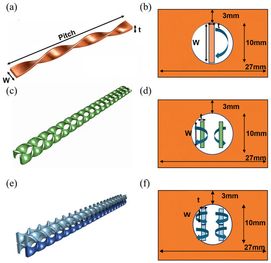
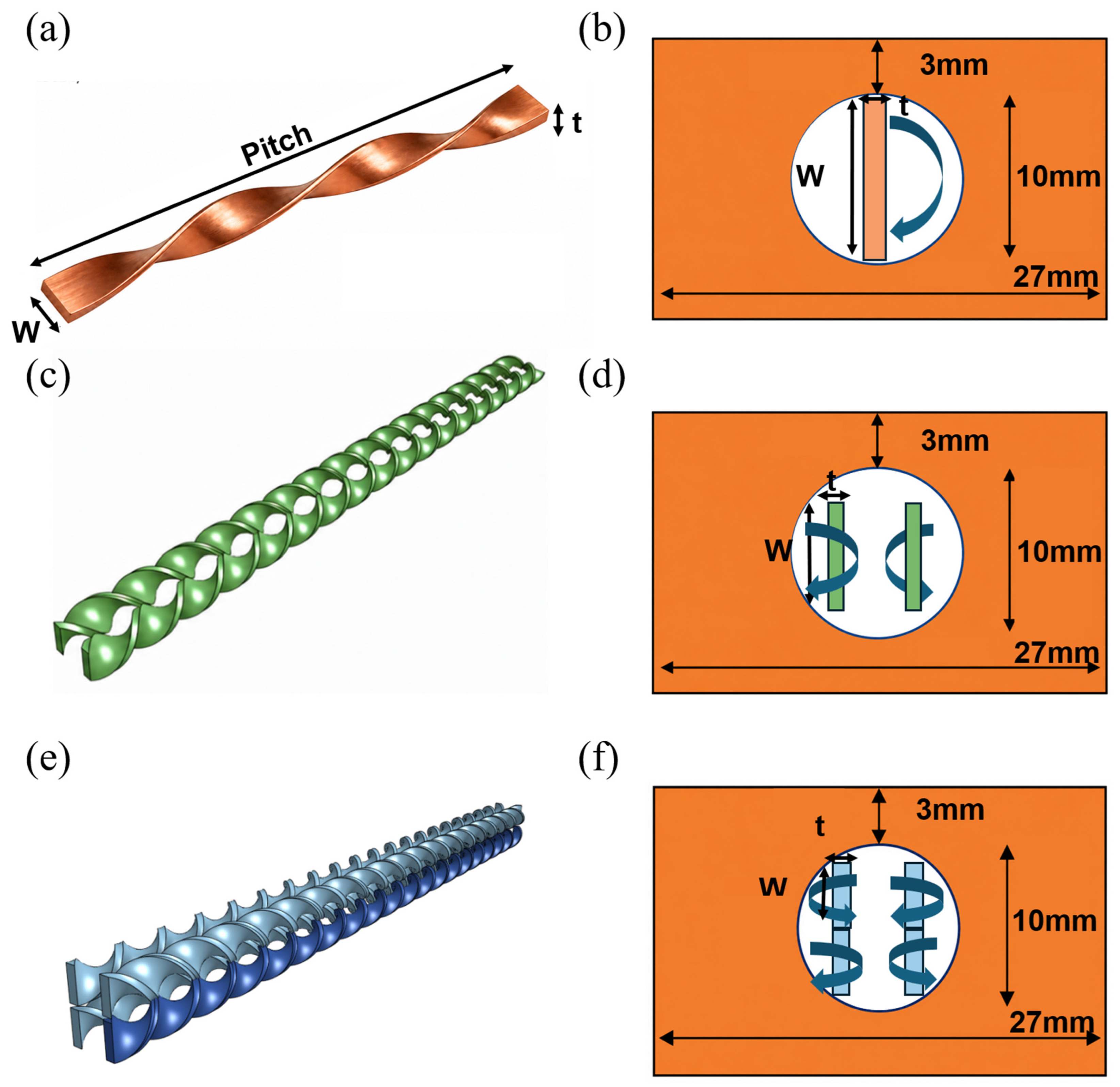
Figure 1 shows the cooling-channel configurations and insert geometries used in this study. The multi-swirl inserts consisted of twisted-tape elements arranged inside the circular tube. For the two-element multi-swirl insert, two twisted tapes were installed with opposite twist directions. For the four-element multi-swirl insert, four twisted tapes were arranged with alternating twist directions. The twist ratio was kept constant for all twisted-tape inserts. This arrangement was used to generate counter-rotating secondary flows inside the circular tube. The smooth tube corresponds to the circular cooling channel without any swirl insert.
Figure 1.
(a) Single-swirl insert tube, (b) section view of single-element swirl insert tube, (c) two-element multi-swirl insert tube, (d) section view of two-element multi-swirl insert tube, (e) four-element multi-swirl insert, and (f) section view of four-element multi-swirl insert.
The twisted-tape dimensions are summarized in Table 2. The tube inner diameter was 10 mm. The total insert length was 168 mm. The width and pitch were 9.5 mm and 28.5 mm for the single-swirl insert, 4 mm and 8 mm for the two-element multi-swirl insert, and 3.5 mm and 7 mm for the four-element multi-swirl insert, respectively. The corresponding insert thicknesses are listed in Table 2.
Table 2.
Design parameters of the swirl insert configurations.
The swirl inserts were fabricated from copper rectangular strips. Each strip was mechanically twisted to the target pitch and twist ratio listed in Table 2. After fabrication, the twisted elements were assembled according to the designed configuration and fixed at both the upstream and downstream ends using thin wires to maintain their relative positions during installation. The assembled insert was then inserted into the circular cooling channel. Because the clearance between the insert assembly and the inner wall of the cooling channel was very small, the insert was tightly fitted inside the tube, and no noticeable lateral movement or rotation was observed after insertion. The angular orientation of the insert assembly relative to the heated surface was fixed during installation, according to the cross-sectional arrangements shown in Figure 1b,d,f. Therefore, the same relative positions between the twisted-tape elements and the heated surface were maintained for repeated tests under one-sided heating conditions.
2.2. Experimental Facility and Test Condition
The experiments were conducted using a closed-loop pressurized water facility for subcooled flow boiling tests under one-sided high-heat-flux heating. The loop consisted of a circulation pump, preheater, pressurization unit, accumulator, test section, heat exchanger, flow meter, pressure transducers, differential-pressure transducer, and thermocouples. The system pressure, inlet temperature, and flow rate were controlled before the coolant entered the test section.
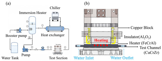
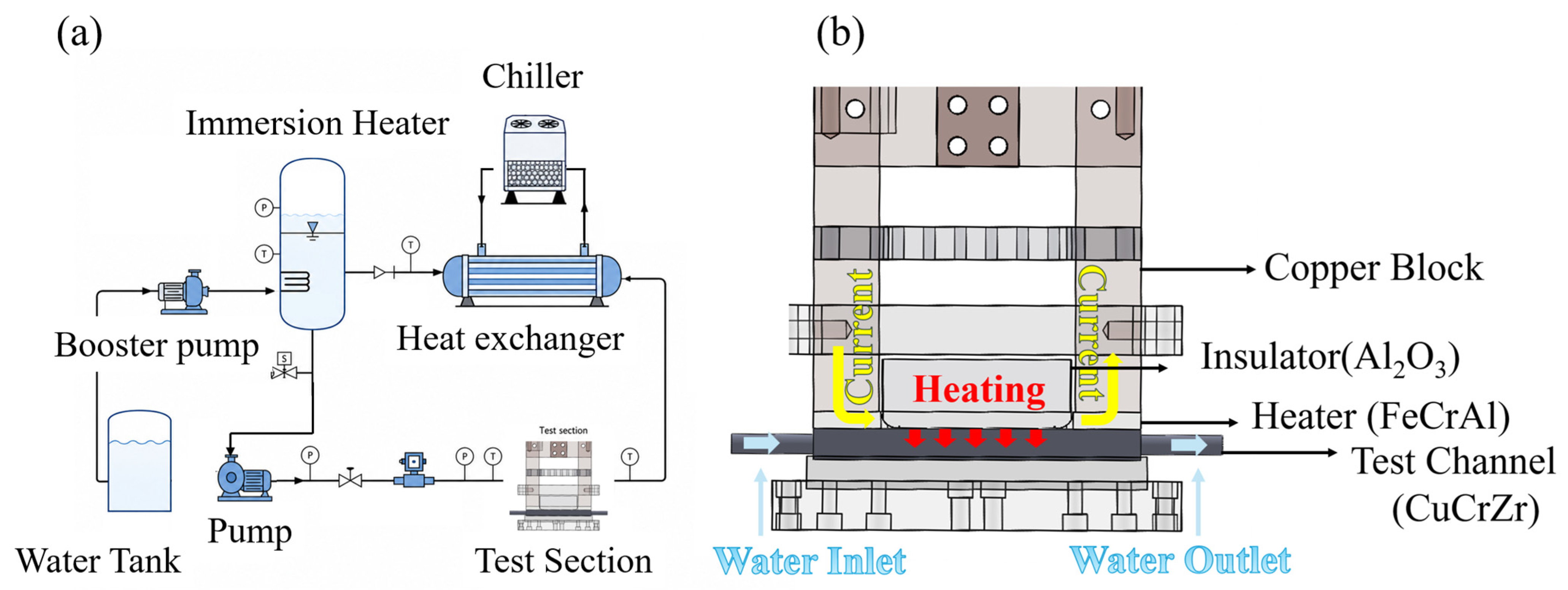
Figure 2 shows the experimental facility, test section, and one-sided Joule heating configuration. Water was circulated by the pump and heated to the target inlet temperature using the preheater. The system pressure was adjusted using the pressurization unit and accumulator. After passing through the test section, the coolant was cooled by the heat exchanger and returned to the loop.
Figure 2.
(a) Experimental facility and (b) Joule heater.
The test section was heated by direct Joule heating [28]. The electrical current was supplied through the heating block, and the heat load was applied mainly from one side of the circular cooling channel. This configuration was used to reproduce a one-sided heating condition, where heat is imposed from the heated side rather than uniformly around the entire tube circumference. During each test, the electrical power was increased stepwise under fixed pressure, inlet temperature, and flow velocity until CHF occurred. The electrical input was used to control the heating level, whereas the heat flux used in the heat transfer and CHF analyses were determined from the local wall-temperature gradient, as described in Section 2.3.
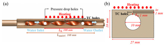
Figure 3 shows the cross-sectional views of the test section and the instrumentation layout. Figure 3a shows the x–z cross-section of the cooling channel. Wall temperatures were measured at several axial locations along the heated length to obtain the wall-temperature distribution during single-phase convection and boiling. Two embedded thermocouples were installed near the heated side at each axial position, and the distance between the upper and lower thermocouples was 1 mm. These thermocouples were used to estimate the wall temperature near the heated surface. The inlet and outlet coolant temperatures were measured using thermocouples installed at the test-section inlet and outlet. Figure 3b shows the y–z cross-section of the test section, including the axial locations of the wall thermocouples and the pressure ports.
Figure 3.
(a) Front view of channel and (b) side view of channel.
The heated length of the test section was 100 mm, as shown in Figure 3. The differential-pressure inlet port was located 100 mm downstream from the channel inlet. The wall-temperature measurement points were located at axial positions of 50, 60, 70, 80, and 90 mm from the beginning of the heated section.
The mass flow rate was measured upstream of the test section using a flow meter. The inlet and outlet pressures were measured using pressure transducers, and the pressure drop across the test section was directly measured using a differential-pressure transducer connected to the pressure ports.
The experiments were conducted at a pressure of 3 bar, an inlet temperature of 103.5 °C, and a flow velocity of 2 m/s. These operating conditions were selected as a controlled reference condition that allowed stable subcooled flow boiling and CHF occurrence within the heat-flux capacity of the experimental facility. The apparatus was designed to impose one-sided high heat fluxes up to approximately 8 MW/m2, and the selected condition enabled a consistent comparison of the smooth tube, the single-swirl insert, the two-element multi-swirl insert, and the four-element multi-swirl insert under the same thermal–hydraulic condition. These conditions were not intended to cover the full operating range of actual divertor cooling systems, but to provide a laboratory-scale high-heat-flux cooling condition for evaluating the relative effects of the proposed insert configurations.
The main measurement ranges and uncertainties are summarized in Table 3. The heat flux range considered in the present experiments was 0–8000 kW/m2. The mass flow rate, inlet temperature, pressure, wall temperature, and pressure drop were measured using calibrated instruments. The data reduction method and uncertainty propagation are described in Section 2.3.
Table 3.
Measurement range and uncertainty.
2.3. Data Reduction and Uncertainty
The local heat flux was calculated from the temperature gradient measured by the embedded thermocouples near the heated side of the test section. At each axial location, two thermocouples were installed with a vertical spacing of 1 mm, as shown in Figure 3. The local heat flux was obtained using one-dimensional heat conduction through the test-section wall:
where is the thermal conductivity of the solid wall, and are the temperatures measured by the upper and lower thermocouples at the -th axial location, and is the distance between the two thermocouples. The magnitude of was used for the heat transfer analysis.
Under one-sided heating of a circular cooling channel, the highest wall temperature and local heat flux occur at the center of the heated side, where CHF was observed in the present experiments. Therefore, the local heat flux was evaluated from the temperature gradient measured by embedded thermocouples aligned with the main heat-flow direction at the heated-side center. Although lateral heat spreading may occur around this region, the one-dimensional wall-normal conduction approximation was used to evaluate the peak local heat flux relevant to CHF. The same data-reduction procedure was applied to all configurations, providing a consistent basis for comparing the relative heat-transfer performance.
The wall temperature at each axial location was estimated by extrapolating the measured temperature to the inner wall surface using the local heat flux:
where is the distance between the upper thermocouple and the inner wall surface. The local bulk fluid temperature was estimated from the inlet and outlet coolant temperatures along the heated length:
where is the axial position of the thermocouple and is the heated length.
The local heat transfer coefficient was then calculated as:
This local heat transfer coefficient was used to compare the heat transfer performance of the smooth tube, single-swirl insert, two-element multi-swirl insert, and four-element multi-swirl insert.
The critical heat flux (CHF) was determined from the local heat flux at the point where a rapid increase in the wall temperature occurred. After the CHF detection, the electrical power was stopped to prevent damage to the test section.
The pressure drop was obtained from the differential-pressure transducer connected to the pressure ports of the test section:
The uncertainty of the calculated quantities was evaluated using standard error propagation:
The uncertainty of the local heat flux was propagated from the uncertainties of the thermocouple temperatures, thermocouple spacing, and thermal conductivity. The uncertainty of the local heat transfer coefficient was propagated from the uncertainties of the local heat flux, wall temperature, and bulk fluid temperature. The main measurement ranges and uncertainties are summarized in Table 3.
2.4. Experimental Reliability: Repeatability Tests and Performance Validation
The reliability of the experimental system was evaluated through repeatability tests and comparisons with existing heat transfer, pressure drop, and CHF correlations. The reference correlations used for the reliability checks are summarized in Table 4. The correlations were used to examine the reliability of the experimental setup, measurements, and data-reduction procedure.
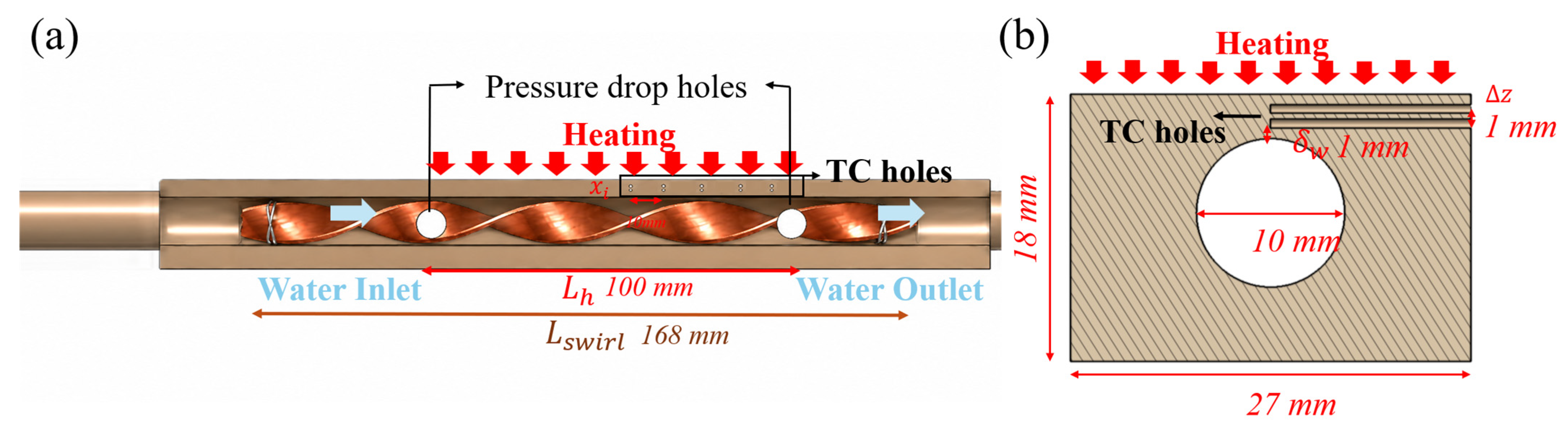
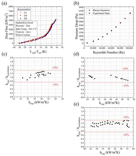
The repeatability test was performed more than three times under the same operating condition. After each test, the loop was cooled down and returned to the initial condition before the next run. As shown in Figure 4a, the repeated boiling curves showed similar wall-superheat behavior over the tested heat-flux range. The repeatability was quantitatively evaluated using the relationship between wall superheat and local heat flux. For local heat fluxes higher than 1000 kW/m2, the maximum wall-superheat deviation among the repeated data was within 3.5 K at a given local heat flux. This result indicates that the present experimental system provided reproducible heat transfer data.
Figure 4.
Experimental reliability: (a) repeatability of boiling curves under the same operating condition, (b) comparison of smooth single-phase pressure drop with the Blasius correlation [29], (c) comparison of smooth single-phase heat transfer coefficients with the Sieder–Tate correlation [30], (d) comparison of single-swirl single-phase heat transfer coefficients with the Manglik and Bergles correlation [22], and (e) comparison of smooth two-phase heat transfer coefficients with the Zhu et al. correlation [31].
The experimental reliability was evaluated through repeatability tests and comparisons with empirical correlations. First, the repeatability test shown in Figure 4a was conducted for the two-element swirl, under the same operating condition. The experiment was repeated more than three times. For local heat fluxes higher than 1000 kW/m2, the maximum wall-superheat deviation among the repeated data was within 3.5 K at a given local heat flux. This result provides an intuitive evaluation of the repeatability of the present boiling heat transfer measurements.
The applicability of the empirical correlations was considered according to the corresponding validation regime. In the circular-tube validation tests, the flow velocity was 2–4 m/s, corresponding to a turbulent Reynolds-number range of approximately 70,000 < Re < 140,000. The Sieder–Tate correlation was used as a reference for turbulent single-phase heat transfer in the smooth circular tube because it is commonly applied to turbulent internal flow, typically for Re > 10,000. The Blasius correlation was used as a reference for smooth-tube single-phase pressure drop. Its conventional applicability range is approximately 4000 < Re < 100,000; therefore, it was used mainly to check the overall pressure-drop trend, although the highest Reynolds-number cases slightly exceeded this range. The Zhu correlation was selected as a reference for subcooled flow boiling heat transfer because it was developed for subcooled boiling in a circular cooling channel under high and non-uniform heat-flux conditions, which is relevant to the present one-sided heating configuration. The original Zhu et al. database covers a mass flux range of approximately 3000–8000 kg/m2 s, while the present validation tests at 2–4 m/s correspond to approximately 1900–3800 kg/m2 s, based on the water density at the present inlet condition. Therefore, the upper part of the present mass flux range is close to the lower range of the Zhu correlation. In addition, the test-section geometry used for the Zhu correlation, consisting of a circular cooling channel embedded in a rectangular heated body, is similar to the present Joule-heated circular-channel configuration. For the single-element swirl tape insert, the Manglik and Bergles correlation was used as a reference for twisted-tape-induced single-phase heat transfer. The original turbulent data range of the correlation is approximately 10,000 < Re < 30,000, whereas the present validation tests were conducted at 70,000 < Re < 140,000. Therefore, the correlation was used only for trend comparison of the single-element swirl tape heat-transfer enhancement, not as a strict predictive model. The Mirshak correlation was used as a reference for CHF under forced-convection water-cooling conditions because the present baseline validation condition is within its reported velocity range of 1.5–13.7 m/s, and the present inlet subcooling of approximately 30 K is also within its reported subcooling range.
The pressure-drop measurement was checked using single-phase flow in the smooth tube. The measured pressure drop was compared with the value calculated from the Blasius correlation over the tested Reynolds-number range. As shown in Figure 4b, the experimental pressure drop showed good agreement with the Blasius correlation. This comparison was used to check the reliability of the pressure transducers and differential-pressure measurement system for the smooth tube baseline case.
The single-phase heat transfer data for the smooth circular tube were compared with the Sieder–Tate correlation. The comparison was performed using the measured heat transfer coefficient before boiling incipience. As shown in Figure 4c, the ratio of the measured heat transfer coefficient to the correlation value was within ±25% in the single-phase region. This agreement indicates that the thermocouple-based local heat-flux evaluation and wall-temperature estimation were reasonable. For the single-swirl insert tests, additional comparisons were performed using empirical correlations applicable to swirl- or twisted-tape-induced heat transfer. The single-phase heat transfer coefficients were compared with the Manglik and Bergles correlation, which has been widely used to estimate heat transfer enhancement in tubes with twisted-tape inserts. The single-swirl single-phase heat transfer data were further compared with the Manglik and Bergles correlation. As shown in Figure 4d, the measured heat transfer coefficients for the single-swirl insert agreed with the correlation values within approximately ±25%. This result indicates that the heat transfer enhancement induced by the swirl insert was reasonably captured in the present experiment.
The two-phase heat transfer data for the smooth circular tube were compared with the Zhu correlation. As shown in Figure 4e, the measured two-phase heat transfer coefficients were within ±25% of the correlation values. This comparison shows that the measured boiling heat transfer trend was consistent with the reference correlation.
The CHF values were compared with the Mirshak correlation. The comparison was made for the baseline validation condition under the corresponding pressure, velocity, and inlet-subcooling conditions. The measured CHF differed from the Mirshak prediction by approximately 18%, which is acceptable for CHF assessment using empirical correlations.
Table 4.
Reference correlations used for experimental reliability checks.
These empirical correlations were used for baseline validation of the experimental measurements and were not intended to directly predict the heat-transfer enhancement produced by the proposed multi-swirl inserts. Because directly comparable experimental data for multi-swirl inserts under one-sided high-heat-flux subcooled flow boiling conditions are limited in the available literature, the smooth circular tube tested in the same facility was used as the primary baseline for evaluating the insert effects. This approach enables a direct comparison among the smooth tube, single-swirl insert, two-element multi-swirl insert, and four-element multi-swirl insert under identical tube geometry, heating configuration, and operating conditions.
3. Results
The subcooled flow boiling experimental results are discussed in terms of critical heat flux, heat transfer coefficient, and pressure drop.
3.1. Critical Heat-Flux Characteristics
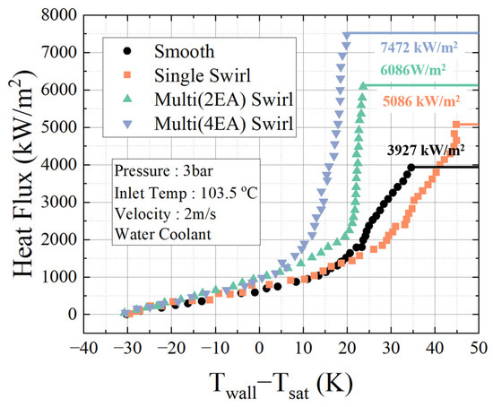
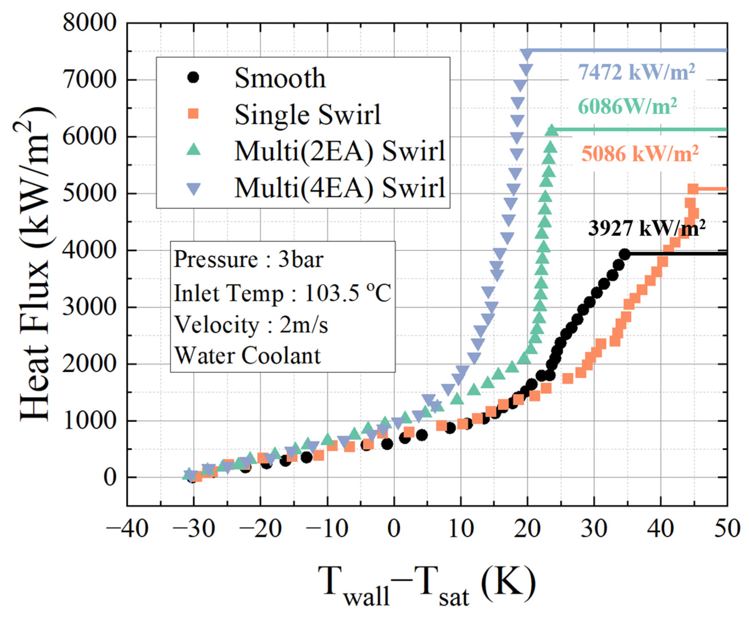
Figure 5 shows the boiling curves of the four cooling-channel configurations. The CHF point was identified from the rapid wall-temperature increase at the end of each boiling curve.
Figure 5.
Boiling curves and CHF points of the four cooling-channel configurations.
The smooth tube showed a CHF of 3927 kW/m2. The CHF increased to 5086 kW/m2 for the single-swirl insert, 6086 kW/m2 for the two-element multi-swirl insert, and 7472 kW/m2 for the four-element multi-swirl insert.
Compared with the smooth tube, the CHF increased by 29.4% for the single-swirl insert, 55.0% for the two-element multi-swirl insert, and 90.3% for the four-element multi-swirl insert. The highest CHF was obtained with the four-element multi-swirl insert.
The CHF increased as the number of swirl elements increased. The two-element multi-swirl insert showed a 19.8% higher CHF than the single-swirl insert, and the four-element multi-swirl insert showed a 47.1% higher CHF than the single-swirl insert. The CHF of the four-element multi-swirl insert was also 22.8% higher than that of the two-element multi-swirl insert.
These results show that the multi-swirl inserts increased the CHF under the present one-sided heating condition. The CHF, local heat transfer coefficient, and pressure drop results are discussed together in Section 4.
3.2. Local Heat Transfer Coefficient Characteristics
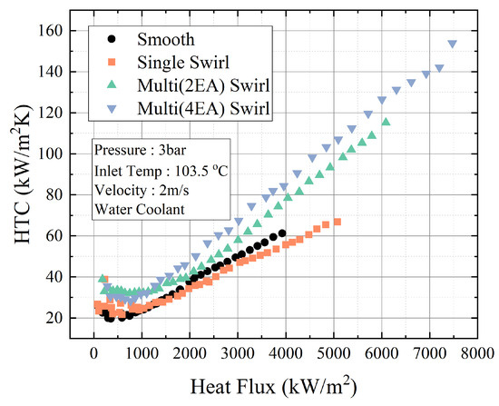
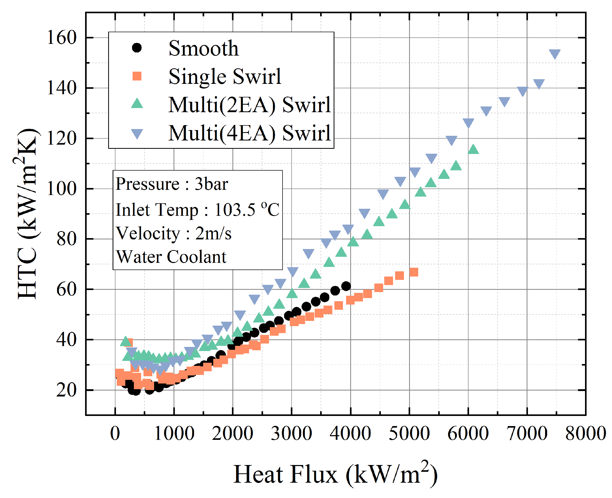
Figure 6 shows the local heat transfer coefficient characteristics of the four cooling-channel configurations. The smooth tube showed a maximum local heat transfer coefficient of 61.2 kW/m2 K. The maximum value increased to 66.8 kW/m2 K for the single-swirl insert, 115 kW/m2 K for the two-element multi-swirl insert, and 154 kW/m2 K for the four-element multi-swirl insert.
Figure 6.
Local heat transfer coefficient characteristics of the four cooling-channel configurations.
Compared with the smooth tube, the maximum local heat transfer coefficient increased by 9.2% for the single-swirl insert, 87.9% for the two-element multi-swirl insert, and 151.6% for the four-element multi-swirl insert. The increment was much larger for the multi-swirl inserts than for the single-swirl insert.
The single-swirl insert showed only a small increase in the maximum local heat transfer coefficient compared with the smooth tube. In contrast, the two-element and four-element multi-swirl inserts showed a clear increase in the local heat transfer coefficient. This result indicates that the multi-swirl configuration was more effective than the single-swirl configuration in enhancing local boiling heat transfer.
The local heat transfer coefficient increased with the number of swirl elements. The four-element multi-swirl insert showed the highest maximum local heat transfer coefficient among the tested configurations. The maximum value of the four-element multi-swirl insert was 33.9% higher than that of the two-element multi-swirl insert.
The observed heat transfer enhancement is consistent with previous studies on swirl and twisted-tape inserts, where secondary flow and flow mixing were reported to improve heat transfer in circular channels [18,20,22]. The detailed mechanism responsible for the stronger enhancement of the multi-swirl inserts is discussed in Section 4.
3.3. Pressure-Drop Characteristics
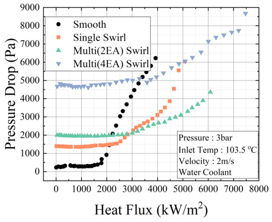
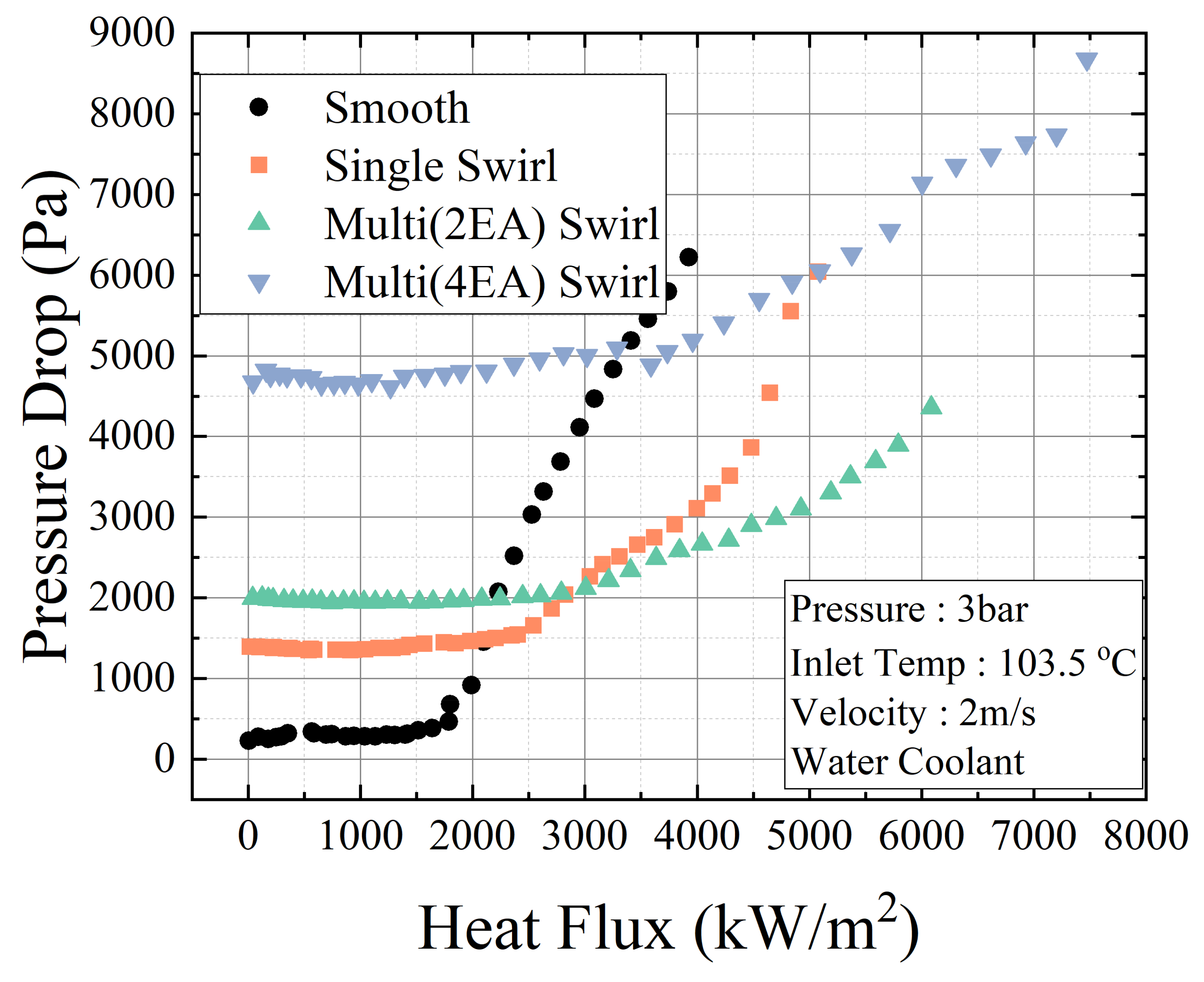
Figure 7 shows the pressure-drop characteristics of the four cooling-channel configurations as a function of heat flux. In the single-phase region, the pressure drop increased with the application of internal inserts.
Figure 7.
Pressure-drop characteristics of the four cooling-channel configurations as a function of heat flux.
The measured single-phase pressure drops were 295 Pa for the smooth tube, 1380 Pa for the single-swirl insert, 1985 Pa for the two-element multi-swirl insert, and 4710 Pa for the four-element multi-swirl insert. The pressure drop order in the single-phase region was as follows: smooth tube < single-swirl insert < two-element multi-swirl insert < four-element multi-swirl insert. This trend shows that the hydraulic resistance increased as the number of swirl-generating elements increased.
In the low-to-intermediate heat-flux region, the pressure-drop behavior was governed by the combined effects of insert-induced hydraulic resistance and boiling-induced two-phase effects. For the insert configurations, geometric blockage and secondary-flow generation produced a baseline pressure drop before the boiling-induced contribution became dominant. This effect was most pronounced for the four-element multi-swirl insert because it had the largest blockage and the strongest secondary-flow generation among the tested configurations. Even at increased heat flux conditions, the flow is maintained at high subcooling, and the bulk flow does not reach saturation while small bubbles generated from the heated side do not increase the pressure drop significantly. Therefore, even though flow boiling was already developed in this heat-flux range, the additional pressure-drop increase caused by vapor generation was relatively small. As a result, the pressure drop of the four-element insert appeared nearly constant at approximately 4500–5000 Pa in the low-to-intermediate heat-flux region. At higher heat fluxes, vapor generation and two-phase interactions became more pronounced, leading to a clearer increase in pressure drop. The pressure-drop curves also indicate a transition associated with the onset of fully developed boiling (OFDB), where the pressure drop begins to increase more rapidly with heat flux. The OFDB was observed at approximately 2000 kW/m2 for the smooth tube, 2500 kW/m2 for the single-element swirl tape insert, 3000 kW/m2 for the two-element swirl tape insert, and 3500 kW/m2 for the four-element swirl tape insert. Compared with the smooth tube, the swirl tape inserts delayed the OFDB, suggesting that swirl-induced mixing and liquid replenishment suppressed local vapor accumulation near the heated side. The two-element swirl tape insert further postponed the OFDB compared with the single-element insert, indicating that localized secondary vortices near the heated side were effective in removing vapor and supplying subcooled liquid to the high-heat-flux region. The four-element swirl tape insert showed the most delayed OFDB; however, the additional delay relative to the two-element insert was approximately 500 kW/m2. This suggests that increasing the number of swirl-generating elements can further delay the boiling transition, but the additional benefit is not necessarily proportional to the accompanying hydraulic penalty.
4. Discussion
The performance evaluation criterion (PEC) is commonly used to evaluate insert-type heat transfer performance by considering both heat transfer enhancement and hydraulic penalty [22,33]. This is particularly important for the present configurations because the inserts improve boiling heat transfer and CHF while simultaneously increasing pressure drop, as shown in Figure 6 and Figure 7.
In this study, the PEC was defined as:
where h and ΔP are the local heat transfer coefficient and pressure drop of each insert configuration, respectively. The smooth tube was used as the reference case. Below the CHF value of the smooth tube, the PEC was calculated using the smooth-tube data at varying heat fluxes. Above the smooth-tube CHF, the reference values were taken from the smooth-tube CHF data because the smooth tube could not be operated at higher heat fluxes. Therefore, PEC values above the smooth-tube CHF should be interpreted as relative performance indices with respect to the limiting smooth tube condition, rather than as direct comparisons with smooth tube data measured at the same heat flux.
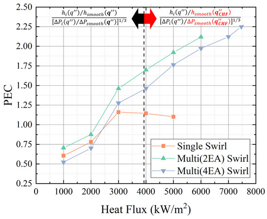
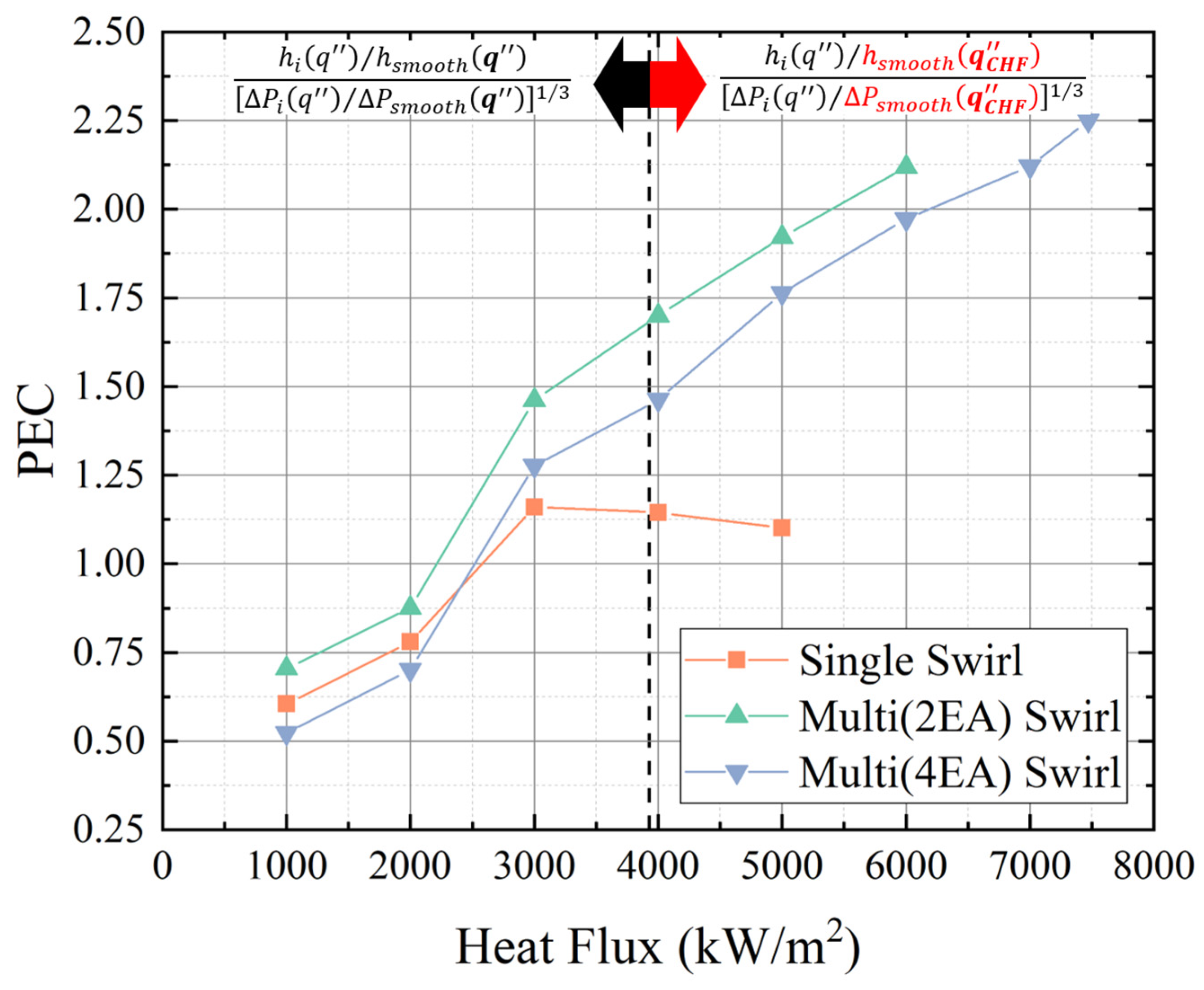
Figure 8 shows the PEC of the insert configurations as a function of heat flux. At low heat fluxes, the PEC values were lower than unity. This indicates that the pressure-drop penalty was larger than the heat transfer enhancement in this region. As the heat flux increased, the PEC values increased above unity for the insert configurations.
Figure 8.
PEC of the insert configurations as a function of heat flux.
The two-element multi-swirl insert showed the highest PEC over most of the intermediate high-heat-flux region. This result can be explained by the balance between heat transfer enhancement and hydraulic penalty. In the single-phase region, the pressure drop mainly depends on geometric blockage and secondary-flow generation. Therefore, the pressure drop increases with the number of swirl-generating elements. However, after the onset of boiling, the pressure-drop behavior is also affected by vapor generation, vapor accumulation, and vapor removal near the heated wall. For example, at approximately 4000 kW/m2, the smooth tube showed the highest pressure drop despite having the lowest single-phase hydraulic resistance. Similarly, the single-swirl insert showed a lower pressure drop than the two-element insert in the single-phase region, but a higher pressure drop in the boiling region. These trends indicate that two-phase pressure drop is governed not only by geometric blockage but also by the ability of each configuration to remove vapor from the heated-side region.
The OFDB behavior provides additional insight into this mechanism. As discussed in Section 3.3, the OFDB was observed at approximately 2000 kW/m2 for the smooth tube, 2500 kW/m2 for the single-element swirl tape insert, 3000 kW/m2 for the two-element swirl tape insert, and 3500 kW/m2 for the four-element swirl tape insert. The delayed OFDB indicates that the swirl tape inserts suppressed rapid vapor accumulation near the heated side by enhancing liquid replenishment and vapor removal. The two-element swirl tape insert delayed the OFDB by approximately 1000 kW/m2 compared with the smooth tube and by approximately 500 kW/m2 compared with the single-element insert. This suggests that the localized secondary vortices generated by the two-element configuration were effective in enhancing the local boiling flow structure near the heated-side high-heat-flux region.
The four-element swirl tape insert showed the most delayed OFDB and achieved the highest local heat transfer coefficient and CHF. This indicates that increasing the number of swirl-generating regions can further enhance local heat transfer and the CHF margin. However, the additional OFDB delay of the four-element insert relative to the two-element insert was approximately 500 kW/m2, whereas the pressure-drop penalty increased more significantly. Therefore, the additional vortical structures in the four-element configuration did not provide a proportional improvement in PEC, although they improved the maximum heat-transfer and CHF performance.
The enhancement of boiling heat transfer and CHF by the multi-swirl inserts can be explained by the modification of the near-wall flow structure under one-sided heating conditions. In the smooth tube, vapor generated near the heated-side wall can remain close to the wall and locally reduce liquid contact, leading to increased wall superheat and earlier CHF. In the single-swirl insert, the large-scale swirling motion promotes core-to-wall mixing and improves liquid transport toward the heated wall. However, the two- and four-element multi-swirl inserts can generate multiple localized secondary flows within the tube cross-section. These localized vortical motions are expected to increase near-wall mixing, disturb vapor accumulation near the heated side, and promote the replacement of vapor by subcooled liquid. As a result, vapor removal from the heated-side region is facilitated, wall superheat is reduced, and the CHF is delayed.
The different roles of the two-element and four-element swirl tape inserts should be interpreted from both thermal and hydraulic viewpoints. The four-element configuration was intended to examine the effect of increasing the number of swirl-generating regions and to maximize heat-transfer and CHF enhancement. As a result, it achieved the highest local heat transfer coefficient and CHF, but it also introduced the largest flow blockage and hydraulic resistance. In contrast, the two-element swirl tape insert provided sufficient boiling enhancement with a smaller relative pressure-drop penalty. Therefore, the two-element configuration showed a more favorable PEC in the intermediate high-heat-flux region, whereas the four-element configuration is more suitable when maximum heat-transfer enhancement or CHF margin is prioritized.
From a practical engineering standpoint, the present results suggest that the proposed two- and four-element swirl tape inserts can be considered as passive enhancement strategies for circular divertor cooling channels subjected to one-sided high-heat-flux loads. In particular, the favorable PEC of the two-element swirl tape insert indicates that the required heat-transfer and CHF enhancement can be achieved with a smaller relative pressure-drop penalty than the four-element configuration. This feature is important for divertor cooling channels, where long circular cooling tubes and high coolant velocities can result in a large system-level pressure drop. Because the insert-type concept can be implemented inside a circular tube without modifying the main cooling-channel geometry, it may provide a practical approach for improving the CHF margin while reducing the reliance on simply increasing the coolant flow rate.
The importance of this hydraulic consideration has also been emphasized in divertor cooling system studies. For example, Di Maio et al. [34] performed a hydraulic assessment of the DEMO divertor plasma-facing-component cooling circuit and evaluated its thermal–hydraulic performance in terms of total pressure drop, coolant axial flow velocity, and CHF margin. Their analysis identified an excessive total pressure drop exceeding 1.4 MPa and an insufficient CHF margin below 1.4 in the initial configuration. By modifying the inlet-manifold branch, the optimized configuration reduced the total pressure drop below 1.4 MPa, increased the minimum CHF margin, and decreased the average coolant velocity to below 10 m/s. Subsequent EU-DEMO studies further emphasized that coolant velocity, total pressure drop, and CHF margin must be simultaneously considered when determining acceptable operating conditions [35,36]. These results indicate that increasing the coolant flow rate to improve the CHF margin can lead to a substantial pressure-drop burden at the system level. Therefore, insert configurations that provide higher CHF or higher PEC at comparable coolant velocity may help reduce the hydraulic burden of long circular divertor cooling channels.
Future work should therefore extend the present experimental database to higher heat-flux ranges and operating conditions that are more representative of practical divertor cooling environments. In particular, it is necessary to evaluate whether the two- and four-element swirl tape inserts can maintain their thermal–hydraulic benefits under actual divertor-relevant conditions, where higher heat-flux removal capability, higher coolant velocity, and stricter pressure-drop constraints are required. In addition, the insert geometry should be further optimized by considering both thermal enhancement and hydraulic penalty. Such optimization should not aim only at maximizing CHF or the heat transfer coefficient, but also at identifying an optimal operating point that balances CHF margin, pressure drop, pumping power, and overall system efficiency. This approach would provide a more realistic basis for assessing the applicability of two- and four-element swirl tape inserts to high-heat-flux divertor cooling channels.
5. Conclusions
In this study, subcooled flow boiling experiments were conducted to evaluate the thermal–hydraulic effects of swirl inserts under one-sided heating conditions. Repeatability tests and comparisons with single-phase, two-phase heat transfer, pressure drop validation, and CHF correlations were performed to confirm the reliability of the experimental facility and data-reduction procedure. For the tested cooling-channel configurations, namely the smooth tube, the single-swirl insert, the two-element multi-swirl insert, and the four-element multi-swirl insert, the main conclusions are as follows:
- The application of swirl inserts improved the CHF under one-sided heating conditions, and the CHF enhancement became more pronounced as the number of swirl-generating elements increased. In particular, the four-element multi-swirl insert provided the highest CHF, corresponding to a 90.3% increase relative to the smooth tube. This indicates that multi-swirl inserts can effectively extend the allowable heat-flux range by enhancing liquid replenishment and vapor removal near the heated-side region.
- The multi-swirl inserts provided a much stronger enhancement in local boiling heat transfer than the conventional single-swirl insert. The maximum local heat transfer coefficient increased by 87.9% for the two-element insert and 151.6% for the four-element insert relative to the smooth tube, whereas the single-swirl insert showed only a limited improvement. This result suggests that multiple localized secondary flows are more effective than a single large-scale swirl for enhancing near-wall mixing under one-sided heating conditions.
- The pressure-drop results showed that the thermal enhancement obtained by the inserts was accompanied by a hydraulic penalty. In the single-phase region, pressure drop increased with the number of swirl-generating elements because of increased flow blockage and stronger secondary-flow generation. In the boiling region, however, pressure-drop behavior was also influenced by vapor generation, vapor accumulation, bubble detachment, and vapor-removal capability near the heated side. The OFDB was delayed from approximately 2000 kW/m2 for the smooth tube to 2500, 3000, and 3500 kW/m2 for the single-element, two-element, and four-element swirl tape inserts, respectively. This indicates that the swirl tape inserts delayed the rapid development of boiling-induced pressure-drop increases by promoting liquid replenishment and vapor removal near the heated-side region.
- The PEC analysis demonstrated that the best insert configuration depends on the target heat-flux range and the allowable pressure-drop or pumping-power limit. Although the four-element swirl tape insert provided the highest CHF and maximum local heat transfer coefficient, it also produced the largest hydraulic resistance. In contrast, the two-element swirl tape insert showed higher PEC values than the four-element insert over several intermediate high-heat-flux conditions, indicating a more favorable balance between boiling enhancement and pressure-drop penalty. Therefore, the four-element configuration is more suitable when maximum heat-transfer enhancement or CHF margin is prioritized, whereas the two-element configuration is more effective when overall thermal–hydraulic efficiency is considered.
- From an engineering perspective, the proposed two- and four-element swirl tape inserts may be promising passive enhancement devices for circular cooling channels subjected to one-sided high-heat-flux loads, such as divertor cooling channels. In particular, the favorable PEC of the two-element swirl tape insert suggests that the CHF margin can be improved with a smaller relative pressure-drop penalty than the four-element configuration. This may help reduce the reliance on simply increasing coolant velocity, which can cause a substantial system-level pressure-drop burden in long circular divertor cooling channels.
- The present study was limited to a fixed operating pressure, inlet temperature, flow velocity, and tube diameter, and selected insert geometries. Future work should extend the experimental database to wider operating conditions, including higher heat-flux ranges and divertor-relevant pressure, mass flux, and inlet-subcooling conditions. In addition, the insert geometry should be further optimized by considering both thermal enhancement and hydraulic penalty. Such optimization should not aim only at maximizing CHF or the heat transfer coefficient, but also at identifying an optimal operating point that balances CHF margin, pressure drop, pumping power, and overall system efficiency. Practical issues such as manufacturing tolerance, mechanical fixation, long-term structural integrity, material compatibility, and erosion or corrosion under high-velocity coolant flow should also be investigated for real divertor cooling applications.
Author Contributions
Y.L.: Conceptualization, Methodology, Validation, Formal Analysis, Investigation, Data Curation, Writing—Original Draft, Writing—Review and Editing. S.L.: Conceptualization, Methodology, Validation, Formal Analysis, Investigation, Data Curation, Writing—Original Draft, Writing—Review and Editing. U.N.: Formal Analysis, Investigation, Writing—Review and Editing. G.L.: Formal Analysis, Investigation, Writing—Review and Editing. D.H.: Methodology, Formal Analysis, Investigation, Writing—Review and Editing. S.K.: Formal Analysis, Investigation, Funding Acquisition. H.J.: Supervision, Project Administration, Funding Acquisition, Resources, Writing—Review and Editing. All authors have read and agreed to the published version of the manuscript.
Funding
This research was supported by the National Research Council of Science & Technology (NST) grant funded by the Korean government (MSIT) (No. GTL25031-000). Additional support was provided by Korea Institute of Energy Technology Evaluation and Planning (KETEP) and the Ministry of Trade, Industry & Energy (MOTIE) of the Republic of Korea (No. RS-2024-00401407).
Data Availability Statement
The original contributions presented in this study are included in the article. Further inquiries can be directed to the corresponding author.
Conflicts of Interest
The authors declare no conflicts of interest.
Abbreviations
The following abbreviations are used in this manuscript:
| CHF | Critical Heat Flux |
| HTC | Heat Transfer Coefficient |
| ONB | Onset of Nucleate Boiling |
| OFDB | Onset of Fully Developed Boiling |
| DEMO | Demonstration Fusion Power Plant |
| PFC | Plasma-Facing Component |
| TC | Thermocouple |
| AlN | Aluminum nitride |
| CuCrZr | Copper–Chromium–Zirconium Alloy |
| FeCrAl | Iron–Chromium–Aluminum Alloy |
| PEC | Performance Evaluation Criterion |
References
- You, J.-H.; Mazzone, G.; Visca, E.; Greuner, H.; Fursdon, M.; Addab, Y.; Bachmann, C.; Barrett, T.; Bonavolontà, U.; Böswirth, B.; et al. Divertor of the European DEMO: Engineering and technologies for power exhaust. Fusion Eng. Des. 2022, 175, 113010. [Google Scholar] [CrossRef] [Scilit]
- Kwon, S.; Im, K.; Hong, S.-H.; Lee, H.; Rognlien, T.D.; Meyer, W.; Kim, K. Recent progress in the design of the K-DEMO divertor. Fusion Eng. Des. 2020, 159, 111770. [Google Scholar] [CrossRef] [Scilit]
- Mou, N.; Lu, M.; Feng, M.; Huang, S.; Han, L.; Yao, D. Numerical study and experimental validation of heat transfer capacity of flat-type divertor for fusion reactor. Nucl. Mater. Energy 2024, 40, 101716. [Google Scholar] [CrossRef] [Scilit]
- Kwon, S.; Park, S.-H.; Kim, H.-T.; Chang, Y.B.; Song, N.H.; Kwag, S.W.; Lee, H.H.; Lee, J.M.; Cho, H.R.; Kim, D.Y.; et al. Engineering evaluation of the upgrade KSTAR divertor system. Fusion Eng. Des. 2025, 216, 115100. [Google Scholar] [CrossRef] [Scilit]
- Oh, H.; Lim, J.H.; Park, M.; Kim, M.H.; Jo, H. Design and assessment of a new divertor plasma facing component containing the Hypervapotron cooling channel and monoblock-type armor. Fusion Eng. Des. 2021, 162, 112101. [Google Scholar] [CrossRef] [Scilit]
- Mudawar, I. Assessment of high-heat-flux thermal management schemes. IEEE Trans. Compon. Packag. Technol. 2001, 24, 122–141. [Google Scholar] [CrossRef] [Scilit]
- Liang, G.; Mudawar, I. Review of channel flow boiling enhancement by surface modification, and instability suppression schemes. Int. J. Heat Mass Transf. 2020, 146, 118864. [Google Scholar] [CrossRef] [Scilit]
- Hu, H.; Xu, C.; Zhao, Y.; Ziegler, K.J.; Chung, J.N. Boiling and quenching heat transfer advancement by nanoscale surface modification. Sci. Rep. 2017, 7, 6117. [Google Scholar] [CrossRef] [Scilit] [PubMed]
- Cattadori, G.; Gaspari, G.P.; Celata, G.P.; Cumo, M.; Mariani, A.; Zummo, G. Hypervapotron technique in subcooled flow boiling CHF. Exp. Therm. Fluid Sci. 1993, 7, 230–240. [Google Scholar] [CrossRef] [Scilit]
- Baxi, C.B. Comparison of swirl tube and hypervapotron for cooling of ITER divertor. In Proceedings of the 16th IEEE/NPSS Symposium on Fusion Engineering, Champaign, IL, USA, 30 September–5 October 1995; IEEE: Piscataway, NJ, USA, 1995; Volume 1, pp. 186–189. [Google Scholar]
- Lim, J.H.; Park, M.G.; Oh, H.G.; Hwang, D.K.; Lee, G.C.; Kim, M.H.; Jo, H. Experimental study of hypervapotron channel with square fin structure for divertor cooling by one-side, electric Joule heating system. Fusion Eng. Des. 2020, 161, 112072. [Google Scholar] [CrossRef] [Scilit]
- Oh, H.; Jo, H. Numerical study of turbulent flow boiling heat transfer in structured cooling channels using lattice Boltzmann method with advanced outlet boundary conditions. Phys. Fluids 2025, 37, 013349. [Google Scholar] [CrossRef] [Scilit]
- Araki, M.; Sato, K.; Suzuki, S.; Akiba, M. Critical-heat-flux experiment on the screw tube under one-sided-heating conditions. Fusion Technol. 1996, 29, 519–528. [Google Scholar] [CrossRef] [Scilit]
- Boscary, J.; Araki, M.; Suzuki, S.; Ezato, K.; Akiba, M. Critical heat flux in subcooled water flow of one-side-heated screw tubes. Fusion Technol. 1999, 35, 289–296. [Google Scholar] [CrossRef] [Scilit]
- Ezato, K.; Suzuki, S.; Dairaku, M.; Akiba, M. Critical heat flux testing on screw cooling tube made of RAFM-steel F82H for divertor application. Fusion Eng. Des. 2005, 75–79, 313–318. [Google Scholar] [CrossRef] [Scilit]
- Liu, P.; Peng, X.B.; Song, Y.T.; Mao, X. Subcooled water flow boiling heat transfer in screw cooling tubes under one-sided heating conditions. Appl. Therm. Eng. 2017, 113, 621–631. [Google Scholar] [CrossRef] [Scilit]
- Liu, P.; Guo, Y.S.; Zheng, W.L.; Song, Y.T.; Peng, X.B.; Tang, M.Y.; Wang, W.H.; Huang, S.F.; Ji, J.D.; Chen, Q.H.; et al. Experiment on critical heat flux of subcooled flow boiling in compound heat transfer tubes. Appl. Therm. Eng. 2021, 199, 117556. [Google Scholar] [CrossRef] [Scilit]
- Schlosser, J.; Escourbiac, F.; Merola, M.; Fouquet, S.; Bayetti, P.; Cordier, J.J.; Grosman, A.; Missirlian, M.; Tivey, R.; Rödig, M. Technologies for ITER divertor vertical target plasma facing components. Nucl. Fusion 2005, 45, 512–518. [Google Scholar] [CrossRef] [Scilit]
- Raffray, A.R.; Schlosser, J.; Akiba, M.; Araki, M.; Chiocchio, S.; Driemeyer, D.; Escourbiac, F.; Grigoriev, S.; Merola, M.; Tivey, R.; et al. Critical heat flux analysis and R&D for the design of the ITER divertor. Fusion Eng. Des. 1999, 45, 377–407. [Google Scholar] [CrossRef] [Scilit]
- Araki, M.; Ogawa, M.; Kunugi, T.; Satoh, K.; Suzuki, S. Experiments on heat transfer of smooth and swirl tubes under one-sided heating conditions. Int. J. Heat Mass Transf. 1996, 39, 3045–3055. [Google Scholar] [CrossRef] [Scilit]
- Liu, P.; Wang, P.T.; Guo, Y.S.; Tang, M.Y.; Song, Y.T.; Peng, X.B.; Wang, W.H.; Ji, J.D.; Chen, Q.H.; Mao, X. Simulation of DNB-type critical heat flux (CHF) and pressure drop in subcooled flow boiling of water for tubes with twisted tape inserts under one-sided heating conditions. Fusion Eng. Des. 2021, 170, 112520. [Google Scholar] [CrossRef] [Scilit]
- Manglik, R.M.; Bergles, A.E. Heat transfer and pressure drop correlations for twisted-tape inserts in isothermal tubes: Part II-Transition and turbulent flows. J. Heat Transf. 1993, 115, 890–896. [Google Scholar] [CrossRef] [Scilit]
- Lim, J.H.; Lee, S.W.; Oh, H.; Park, M.; Hwang, D.; Kim, M.H.; Jo, H. Heat-transfer characteristics of screw tube in one-side high heat load condition for fusion reactor divertor application. Int. J. Adv. Nucl. React. Des. Technol. 2021, 3, 213–225. [Google Scholar] [CrossRef] [Scilit]
- Eiamsa-ard, S.; Thianpong, C.; Eiamsa-ard, P.; Promvonge, P. Turbulent heat transfer enhancement by counter/co-swirling flow in a tube fitted with twin twisted tapes. Exp. Therm. Fluid Sci. 2010, 34, 53–62. [Google Scholar] [CrossRef] [Scilit]
- Vashistha, C.; Patil, A.K.; Kumar, M. Experimental investigation of heat transfer and pressure drop in a circular tube with multiple inserts. Appl. Therm. Eng. 2016, 96, 117–129. [Google Scholar] [CrossRef] [Scilit]
- Dalkılıç, A.S.; Uluç, B.; Cellek, M.S.; Celen, A.; Jumpholkul, C.; Newaz, K.S.; Wongwises, S. Single phase flow heat transfer characteristics of quad-channel twisted tape inserts in tubes. Int. Commun. Heat Mass Transf. 2020, 118, 104835. [Google Scholar] [CrossRef] [Scilit]
- Eiamsa-ard, S.; Changcharoen, W.; Beigzadeh, R.; Eiamsa-ard, P.; Wongcharee, K.; Chuwattanakul, V. Influence of co/counter arrangements of multiple twisted-tape bundles on heat transfer intensification. Chem. Eng. Process. Process Intensif. 2021, 160, 108304. [Google Scholar] [CrossRef] [Scilit]
- Hwang, D.; Park, M.; Oh, H.; Lim, J.H.; Kim, M.H.; Chai, K.-B.; Jo, H. Development of a high heat flux electric Joule heating system for testing a one-side heated cooling channel. Fusion Sci. Technol. 2022, 78, 220–242. [Google Scholar] [CrossRef] [Scilit]
- Blasius, H. Das Ähnlichkeitsgesetz bei Reibungsvorgängen in Flüssigkeiten. VDI Forsch. 1913, 131, 1–41. [Google Scholar] [CrossRef] [Scilit]
- Sieder, E.N.; Tate, G.E. Heat transfer and pressure drop of liquids in tubes. Ind. Eng. Chem. 1936, 28, 1429–1435. [Google Scholar] [CrossRef] [Scilit]
- Zhu, G.; Bi, Q.; Cai, L.; Yan, J.; Lv, H. Subcooled flow boiling heat transfer of water in a circular channel with a twisted tape insert under high and non-uniform heat fluxes. Appl. Therm. Eng. 2018, 138, 722–730. [Google Scholar] [CrossRef] [Scilit]
- Mirshak, S.; Durant, W.S.; Towell, R.H. Heat Flux at Burnout; DP-355; Savannah River Laboratory, E.I. du Pont de Nemours & Co.: Aiken, SC, USA, 1959. [Google Scholar]
- Webb, R.L. Performance evaluation criteria for use of enhanced heat transfer surfaces in heat exchanger design. Int. J. Heat Mass Transf. 1981, 24, 715–726. [Google Scholar] [CrossRef] [Scilit]
- Di Maio, P.A.; Burlon, R.; Mazzone, G.; Quartararo, A.; Vallone, E.; You, J.H. Hydraulic assessment of an upgraded pipework arrangement for the DEMO divertor plasma facing components cooling circuit. Fusion Eng. Des. 2021, 168, 112368. [Google Scholar] [CrossRef] [Scilit]
- Quartararo, A.; Di Maio, P.A.; Vallone, E. ADRANOS: A numerical tool developed to analyse coolant operating conditions of the EU-DEMO divertor. Fusion Eng. Des. 2023, 197, 114055. [Google Scholar] [CrossRef] [Scilit]
- Quartararo, A.; Basile, S.; Bongiovì, G.; Burlon, R.; Castrovinci, F.M.; Catanzaro, I.; Chiovaro, P.; Di Maio, P.A.; Mazzone, G.; Vallone, E.; et al. Hypothetical porous medium concept as a virtual swirl tape: A novel modelling technique towards efficient CFD simulation of swirl tape cooling pipe. Fusion Eng. Des. 2024, 200, 114240. [Google Scholar] [CrossRef] [Scilit]

Disclaimer/Publisher’s Note: The statements, opinions and data contained in all publications are solely those of the individual author(s) and contributor(s) and not of MDPI and/or the editor(s). MDPI and/or the editor(s) disclaim responsibility for any injury to people or property resulting from any ideas, methods, instructions or products referred to in the content. |
© 2026 by the authors. Licensee MDPI, Basel, Switzerland. This article is an open access article distributed under the terms and conditions of the Creative Commons Attribution (CC BY) license.