


Abstract
This paper addresses the problem of improving the efficiency of the traction electric drive of an agricultural electric vehicle operating under variable load conditions typical of agricultural transportation. The study substantiates the feasibility of employing a low-power (2 kW) induction motor as a cost-effective, technically robust, and reliable solution for mobile power systems. Particular attention is given to the operating characteristics of the traction drive under fluctuating loading conditions, which significantly affect the energy efficiency and overall performance of agricultural electric vehicles. A comprehensive structural and mathematical model of the induction motor was developed based on a proprietary implementation without the use of standard MATLAB R2020b/Simulink library blocks. The model was formulated using the transformation of a three-phase coordinate system into a two-phase stationary α–β reference frame, enabling a more accurate representation of the electromagnetic and electromechanical processes occurring within the machine. The analysis was carried out with consideration of transient processes, dynamic characteristics, and energy performance under realistic conditions regarding the influence of control strategies on the energy consumption of the electric drive system. The results of this can be applied to the design and optimization of electric transportation systems for agricultural applications, as well as to the development of energy-efficient control algorithms for traction electric motors.
1. Introduction
The current stage of industrial and agricultural development is characterized by the widespread adoption of energy-efficient and environmentally sustainable technologies. In both industrial logistics and agricultural production, increasing attention is being directed toward trackless electric vehicles, which offer enhanced mobility, maneuverability, and reduced environmental impact compared with conventional transport systems. Battery-powered electric vehicles equipped with electric drivetrains provide a practical solution for a wide range of transportation tasks. Their key advantages include autonomous operation, convenient recharging from the electrical grid, and efficient utilization in enclosed environments where the reduction in exhaust emissions and noise levels is of particular importance. A key component of the powertrain in such vehicles is the traction electric drive, which generates the propulsive force and ensures the required dynamic and operational performance. Compared with conventional internal combustion engine (ICE)-based systems, electric drives offer higher energy efficiency, lower noise levels, a simplified mechanical structure, and enhanced operational safety due to the lower center of gravity of the vehicle. In addition, electric motors are capable of delivering maximum torque at low rotational speeds, which is particularly advantageous under variable load conditions and during frequent start–stop operating cycles [1]. In modern electric vehicles, traction systems increasingly employ induction motor drives based on three-phase squirrel-cage induction machines. This type of electrical machine is characterized by high mechanical robustness, reliability, and resistance to dust, vibration, and other adverse operating conditions. The absence of a brush–commutator assembly reduces maintenance requirements and contributes to an extended service life. Another significant advantage is the high level of industrial standardization and automation in the manufacturing of induction machines, which ensures consistent performance characteristics, lowers production costs, and enhances their economic viability for widespread application [1,2]. The application of induction motor traction drives in trackless industrial electric vehicles enables the implementation of efficient speed and torque control strategies adapted to varying operating conditions. However, achieving high levels of energy efficiency and operational reliability largely depends on the selected control system and the accuracy of the mathematical representation of the underlying electromechanical processes. Therefore, the development and investigation of an induction motor traction drive for agricultural trackless electric vehicles constitute a relevant scientific and engineering challenge aimed at improving the efficiency, reliability, and economic performance of electric transportation systems [2]. To achieve the stated objective, the following research tasks were defined:
- −
- To analyze the application-specific characteristics of induction motors in traction electric drives for agricultural electric vehicles;
- −
- To develop mathematical models of an induction traction drive in both stationary and rotating reference frames;
- −
- To implement simulation models of the induction motor and the frequency converter–induction motor system in the MATLAB/Simulink environment;
- −
- To investigate transient processes, mechanical characteristics, and energy efficiency indicators under various operating conditions;
- −
- To develop and evaluate a simulation model of the frequency converter–induction motor–electric vehicle system for the assessment of traction and load performance;
- −
- To determine the suitability of the proposed electric drive for agricultural electric vehicle applications based on the obtained modeling results [3].
Recent studies have extensively investigated traction motor technologies, electric vehicle propulsion systems, and advanced control strategies for induction and permanent magnet motors. Existing research has primarily focused on motor control algorithms, comparative assessments of traction machine technologies, and drive systems for general electric vehicle applications. However, limited attention has been devoted to the development and analysis of mathematical models of induction motor traction drives operating under variable load conditions characteristic of agricultural electric vehicles. In particular, the influence of realistic traction loads, vehicle dynamics, and operating conditions on the dynamic and energy performance of low-power induction motor drives remains insufficiently investigated. Therefore, the objective of this study is to develop and analyze a mathematical model of a variable-frequency induction motor traction drive for agricultural electric vehicle applications.
2. Materials and Methods
In this study, the transient behavior of the induction motor was investigated in the stationary α–jβ reference frame using a MATLAB-based simulation environment. Dynamic operating conditions of the electric drive were modeled and analyzed to evaluate the electromechanical response and performance characteristics of the traction drive system.
The analysis of dynamic energy conversion processes in induction motors is inherently challenging because of the strongly nonlinear nature of the governing equations. The source of this nonlinearity lies in the multiplicative coupling of state variables within the mathematical model, which complicates both analytical investigation and numerical simulation of the electromechanical processes occurring in the machine.
Consequently, the analysis of the dynamic characteristics of the induction motor is most appropriately conducted using computer-based simulation techniques implemented in the MATLAB environment. Such an approach enables the efficient investigation of complex nonlinear electromechanical processes and facilitates the evaluation of motor performance under various operating conditions [4].
The induction motor is modeled using absolute units, since modern numerical computing environments, such as MATLAB, provide built-in mechanisms for automatic scaling and parameter handling. As a result, the developed modeling framework remains universally applicable and can be readily adapted to induction motors with different power ratings and design parameters without requiring fundamental modifications to the mathematical formulation.
The mathematical model of the induction motor is formulated in the stationary α–β reference frame, where the electrical and magnetic quantities are represented by their projections onto the orthogonal axes of a stationary Cartesian coordinate system. Such a transformation simplifies the description of electromechanical processes and facilitates numerical simulation of the machine dynamics. In this framework, the state vectors are expressed as follows (1) [5]:
where —the stator winding voltage vector in the stationary reference frame;
—the stator winding current vector in the stationary reference frame;
—the stator winding flux linkage vector in the stationary reference frame;
—the rotor winding current vector in the stationary reference frame.
Here denotes the component of the stator winding flux linkage vector oriented along the a-axis of the stationary reference frame;
denotes the component of the stator winding flux linkage vector oriented along the b-axis of the stationary reference frame.
The governing equations can therefore be expressed in the following form (2):
Here t denotes the α-axis component of the stator voltage vector in the stationary α–β reference frame, V;
= −t denotes the β-axis component of the stator voltage vector in the stationary α–β reference frame, V;
Following the mathematical transformations, the governing equations are represented in operator form as (3):
The electromagnetic torque is determined by the following expression (4):
The mechanical equation of motion is represented in operator form as (5):
Equivalent electromagnetic time constant (6):
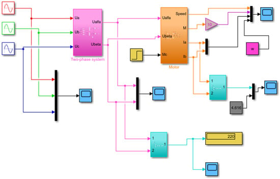
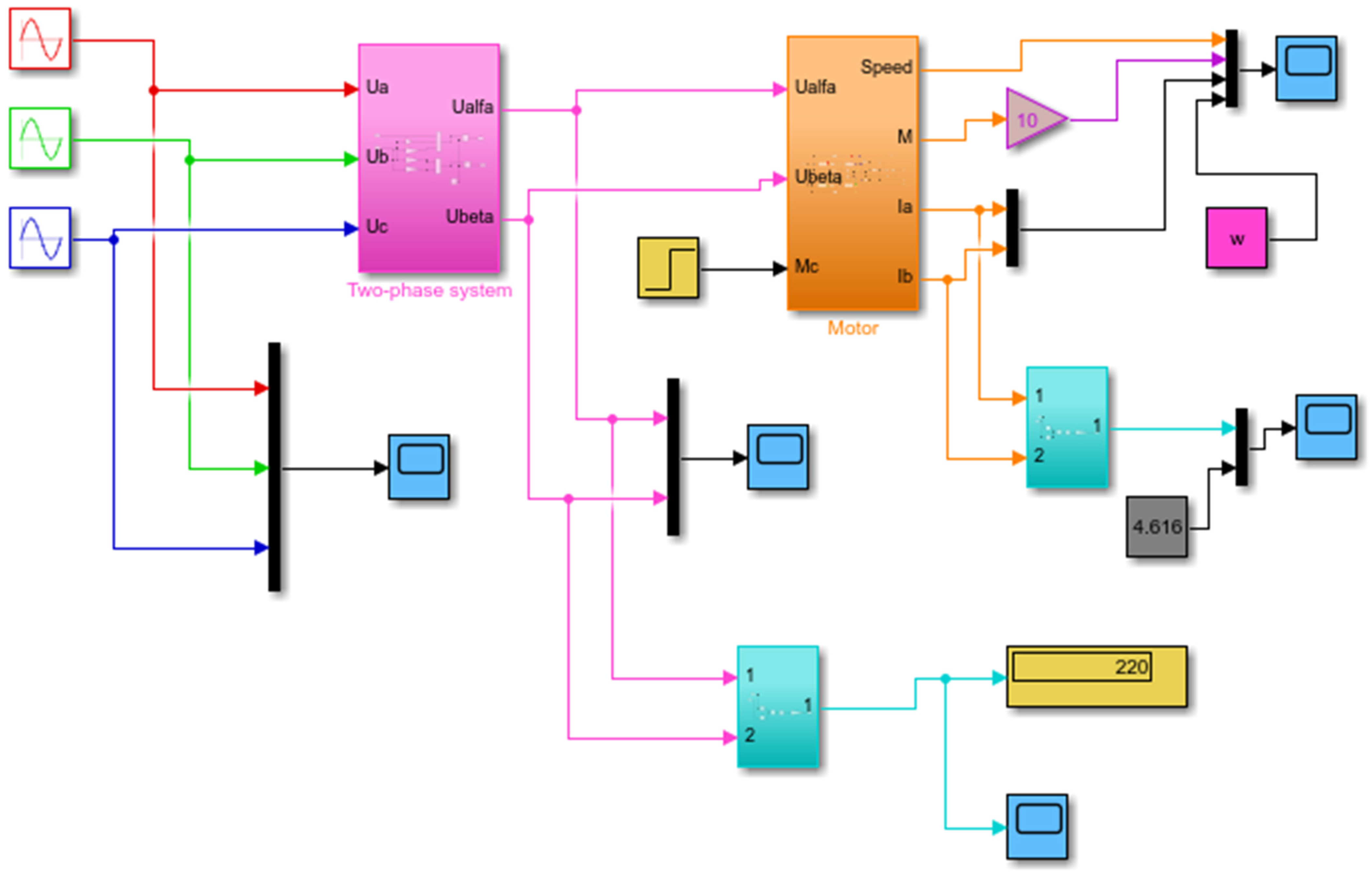
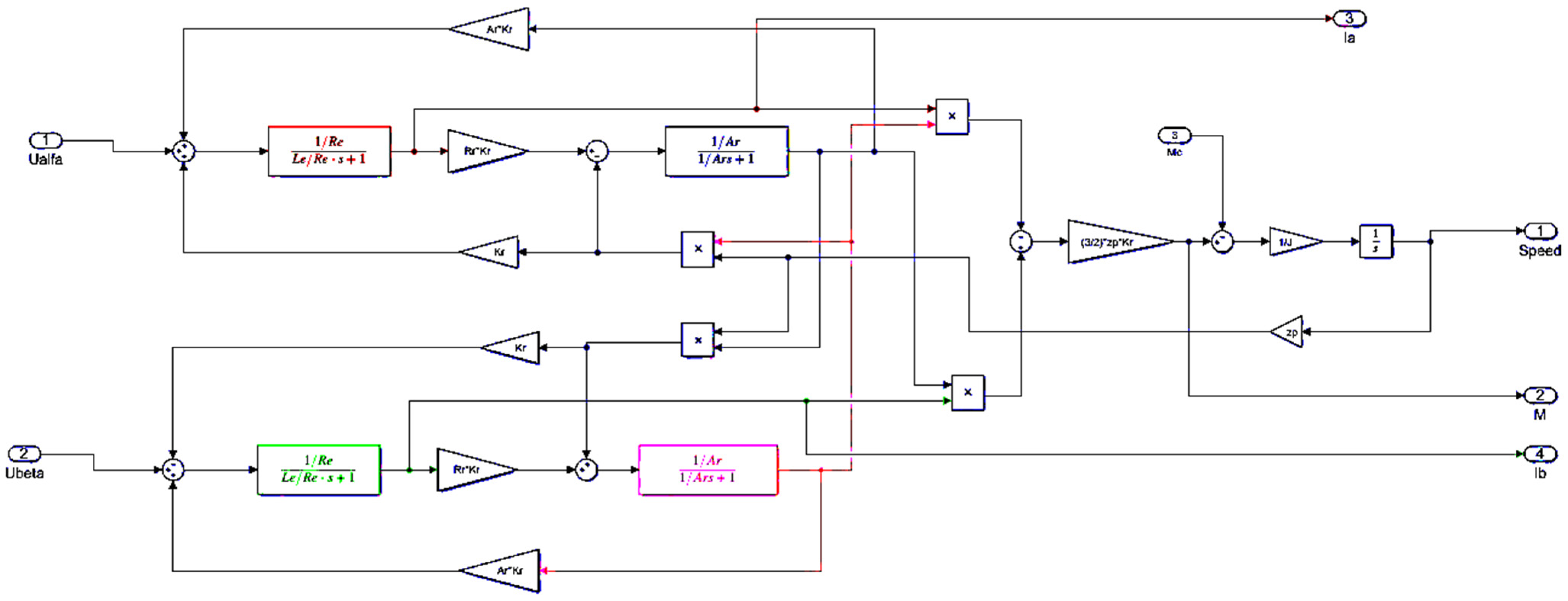
Figure 1 presents the MATLAB-based simulation model of the 4A80V2U3 squirrel-cage induction motor. The model was developed in the stationary (α–β) reference frame in accordance with the mathematical formulation described by the governing equations presented above. The simulation framework provides a basis for investigating the dynamic and electromechanical behavior of the motor under various operating conditions [2].
Figure 1.
Simulation model of the 4A80V2U3 induction electric motor. The conversion of a three-phase system into a two-phase Cartesian representation is commonly interpreted as replacing the physical three-phase machine with an equivalent generalized two-phase model. This transformation simplifies the mathematical description of the machine while preserving its fundamental electromechanical characteristics. The coordinate transformation given by Equation (7), which converts three-phase variables into the stationary (α–β) reference frame, is commonly referred to as the Clarke transformation [6].
The simulation model of the induction motor was parameterized using the manufacturer’s rated data presented in Table 1, Table 2 and Table 3. These parameters served as the basis for the development and validation of the mathematical model and the subsequent analysis of the motor’s dynamic performance.
Table 1.
Nameplate and rated parameters of the 4A80V2U3 squirrel-cage induction motor.
Table 2.
Nameplate and rated parameters of the 4A80V2U3 squirrel-cage induction motor.
Table 3.
Parameters of the equivalent circuit of the 4A80V2U3 squirrel-cage induction motor.
The electric vehicle simulation model was parameterized using the manufacturer’s rated specifications listed in Table 4. These data served as the basis for the analysis of the vehicle’s traction and dynamic performance under the considered operating conditions. Table 4.
Table 4.
Electric vehicle parameters used for simulation.
In the developed induction motor simulation model, the calculated variables are assigned to dedicated functional blocks in accordance with the physical processes taking place within the machine. This structural organization facilitates the representation of the underlying electromechanical phenomena and improves the clarity of the simulation framework (Table 5).
Table 5.
Induction motor and electric vehicle parameters used in the simulation model.
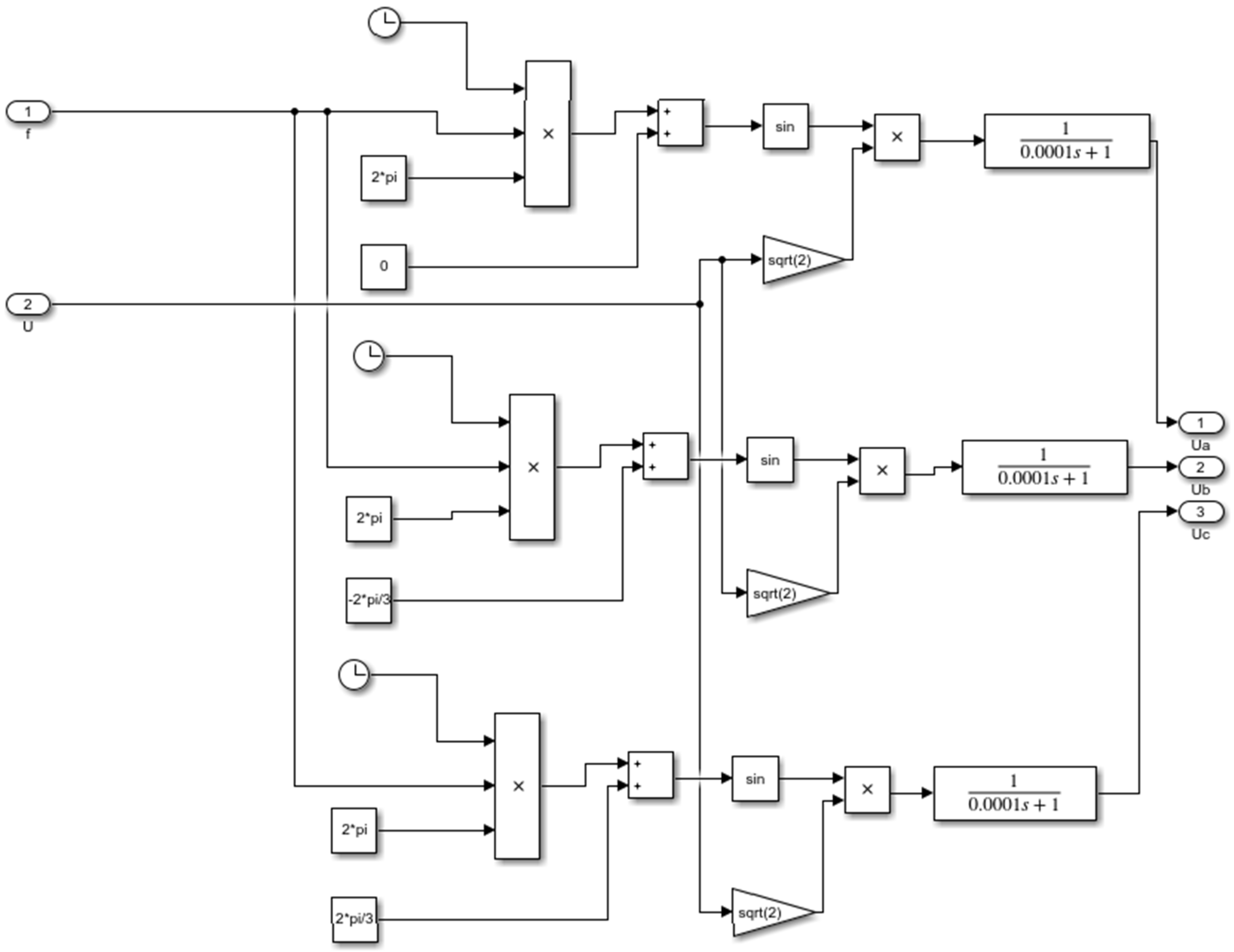
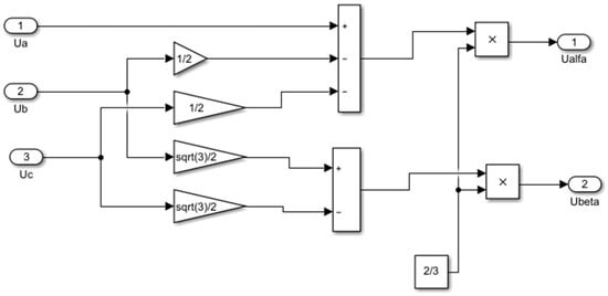
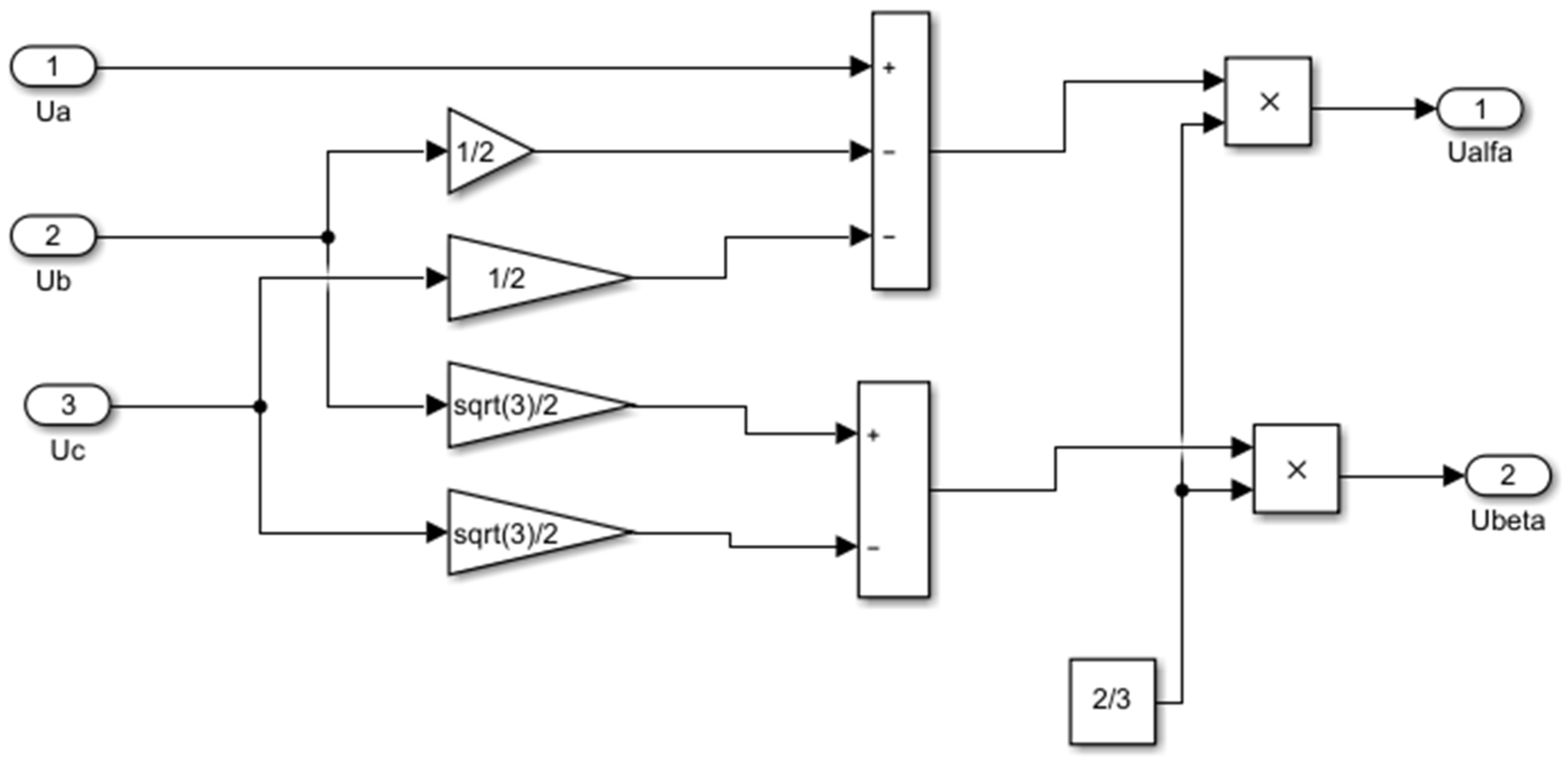
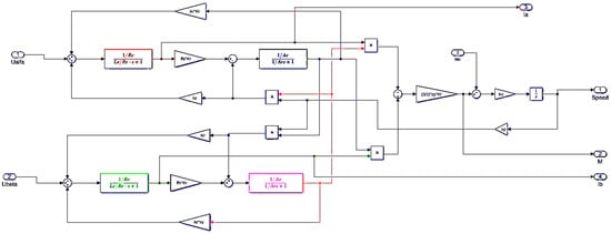
The simulation model of the Clarke transformation block, responsible for converting three-phase variables into the stationary (alpha–beta) reference frame, is presented in Figure 2. Figure 3 illustrates the simulation model of the Motor subsystem corresponding to the 4A80V2U3 squirrel-cage induction motor and implementing the mathematical equations of the machine model [2].
Figure 2.
Cartesian Transformation Block.
Figure 3.
4A80V2U3 Induction Motor Block.
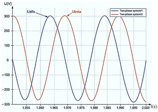
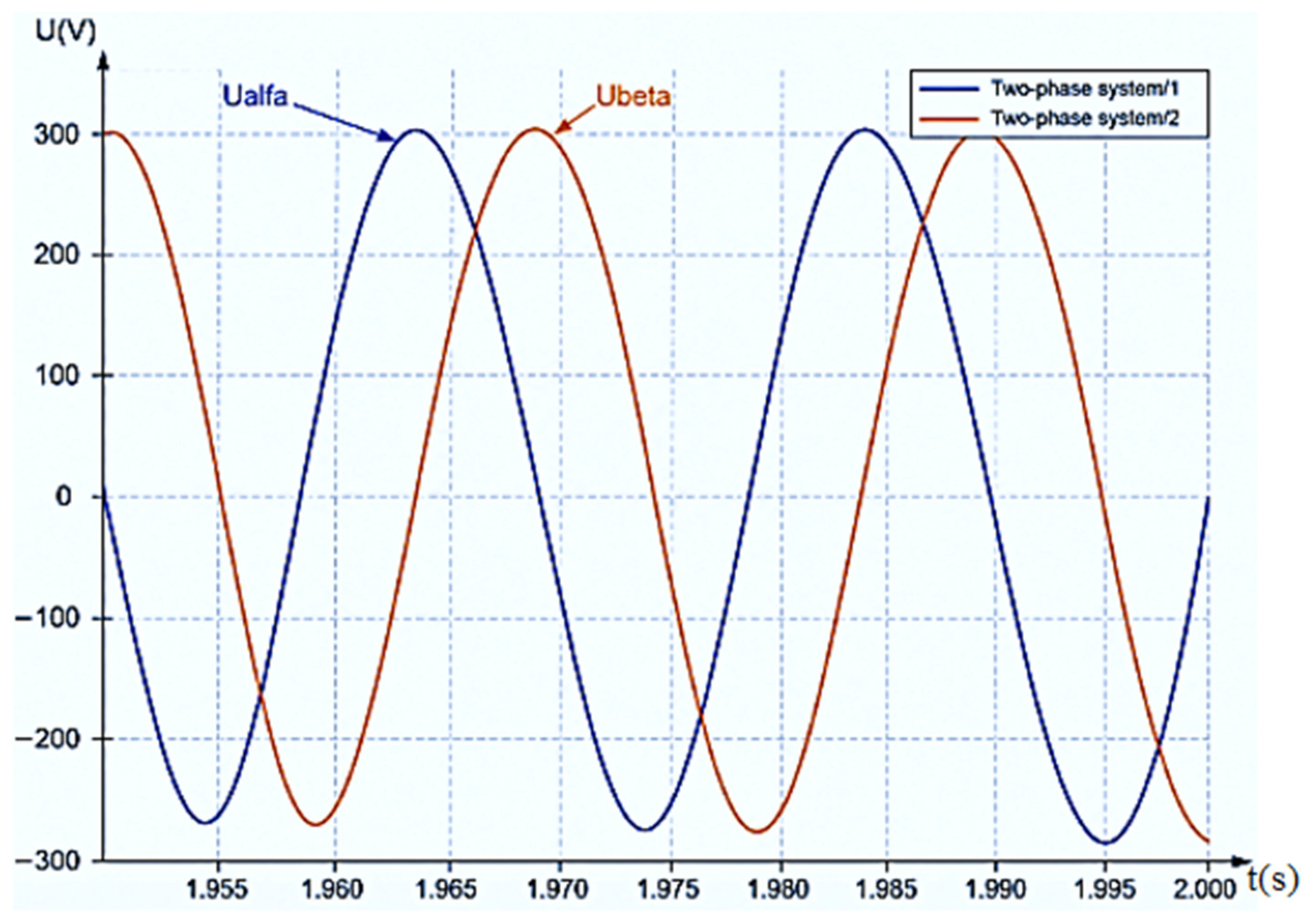
The voltage components (Ualpha) and (Ubeta) are sinusoidal time-varying signals of equal amplitude and frequency, displaced in phase by 90° electrical degrees. These components constitute an orthogonal stationary (α–β) reference frame, in which the resulting voltage space vector maintains a constant magnitude while rotating at the angular velocity—(ω) (Figure 4). This representation provides a convenient framework for analyzing the electromagnetic processes and dynamic behavior of the induction motor.
Figure 4.
Waveforms of the two-phase voltage components Ualfa and Ubeta.
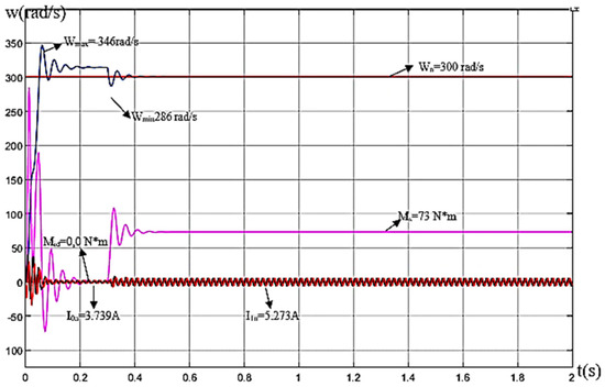
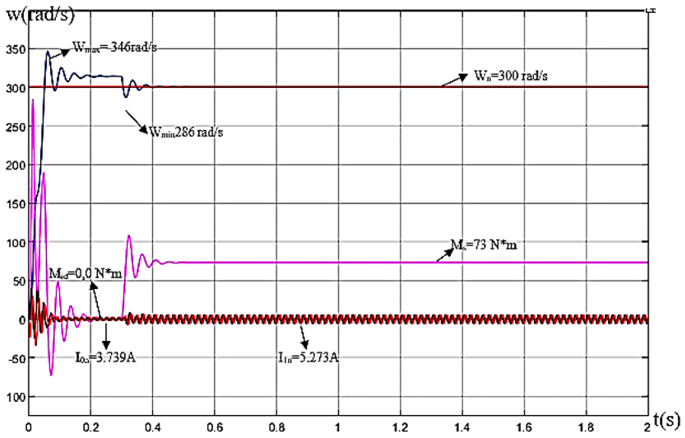
Figure 5 illustrates the transient behavior of the induction motor during direct-on-line starting. The figure presents the time-dependent characteristics of electromagnetic torque (M), angular speed (w), and stator current components Iα and Iβ. The speed response ω = f(t) characterizes the motor acceleration process from standstill to steady-state operation following direct connection to the electrical supply network.
Figure 5.
Time-domain characteristics of electromagnetic torque (M), angular speed (w), and stator current components (Iα, and Iβ) during the direct-on-line starting of the induction motor. The speed response ω = f(t) illustrates the transient acceleration process from standstill to steady-state operation.
In response to the applied load disturbance, the motor speed decreased and subsequently settled at the rated value of . Under steady-state conditions, the electromagnetic torque converged to the static load torque on the motor shaft, reaching m, thereby satisfying the mechanical equilibrium condition. Furthermore, the stator current remained close to its rated value of (3.739 A), confirming stable motor operation and consistency with the expected steady-state performance characteristics of the drive system [7]:
where —peak value of the rated stator current;
—RMS value of the rated stator current.
The developed simulation model was evaluated through a series of verification tests based on the rated parameters of the induction motor (Figure 1).
First, the model was evaluated using the manufacturer’s rated motor parameters.
A rated load torque, (Mn), was subsequently applied to the motor shaft. The simulation results demonstrated stable operation under rated loading conditions. Following the introduction of a short-duration load disturbance lasting (0.5 s), the rotor speed recovered and settled at the rated value, (wn) confirming the correctness of the mechanical and electromechanical model representation (Figure 5).
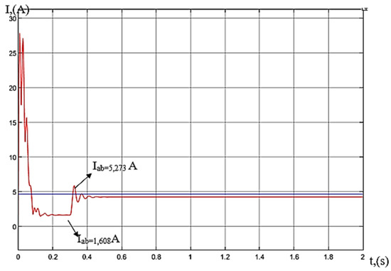
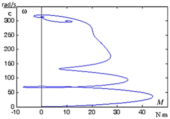
The model was further verified by analyzing the stator current response. For a stator current of , the application of the load resulted in a transient current variation, followed by convergence to the expected steady-state value. This behavior is consistent with the theoretical operating characteristics of the induction motor and indicates the internal consistency of the developed simulation model (Figure 6).
Figure 6.
Time-domain transient response of the stator current during I1 = f(t) direct-on-line starting of the induction motor. The figure presents the RMS values of the stator current components—Ia, Ib expressed in the stationary—Ia, Ib reference frame.
In the stationary reference frame, the stator current components exhibit sinusoidal time-dependent behavior, reflecting the periodic nature of the electromagnetic processes occurring within the induction motor (Figure 6).
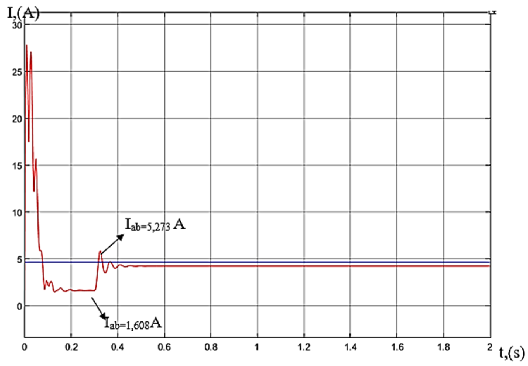
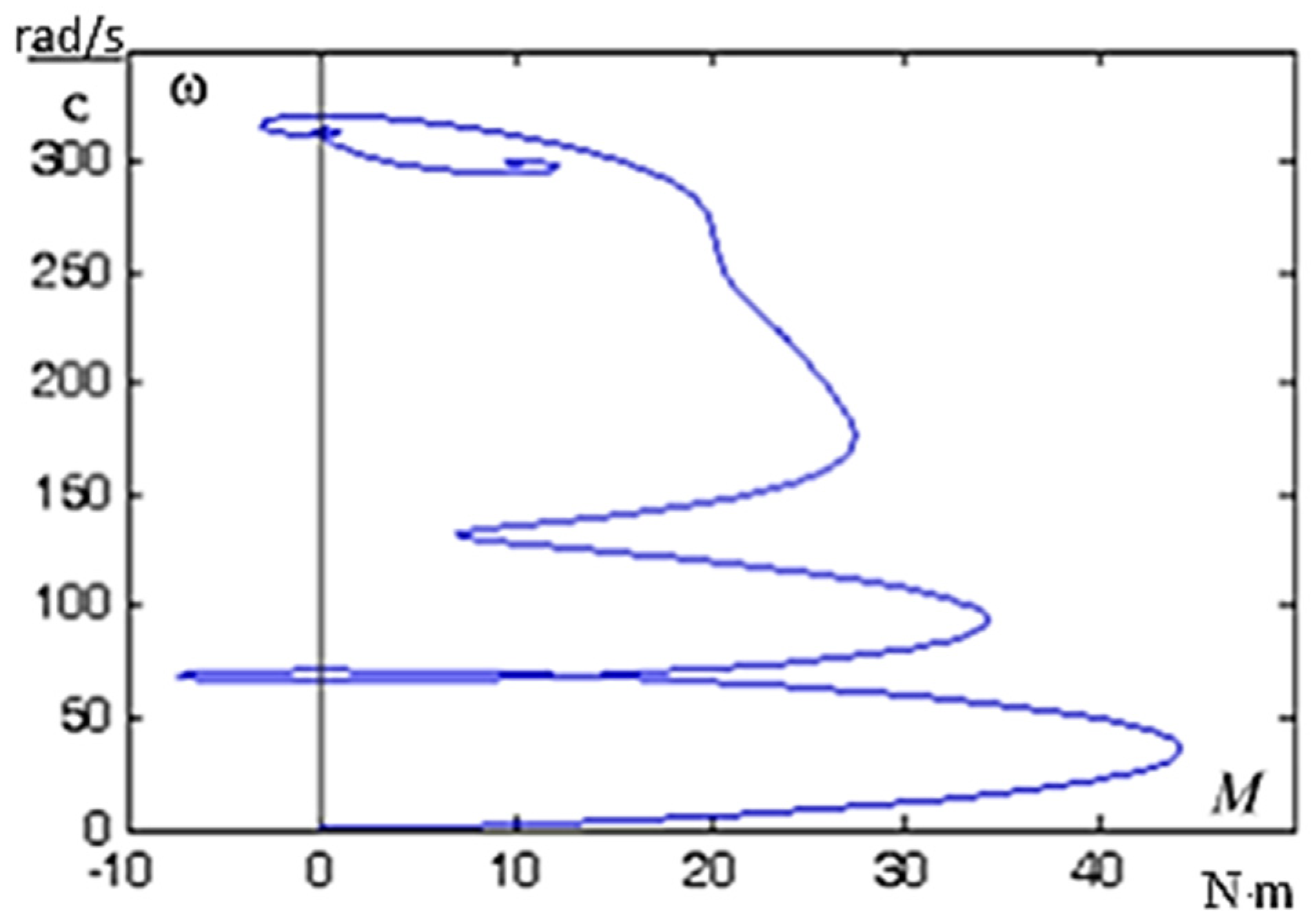
Based on the transient response calculations (Figure 7), the dynamic mechanical characteristic of the induction motor was obtained for direct-on-line starting followed by a load step up to . Using the results of the transient process analysis (Figure 7), the dynamic mechanical characteristic of the induction motor was constructed for the direct-on-line starting condition followed by a step application of the load torque to . The resulting characteristic reflects the electromechanical response of the motor during acceleration and subsequent adaptation to the applied load.
Figure 7.
Dynamic mechanical characteristic of the induction motor obtained during direct-on-line starting.
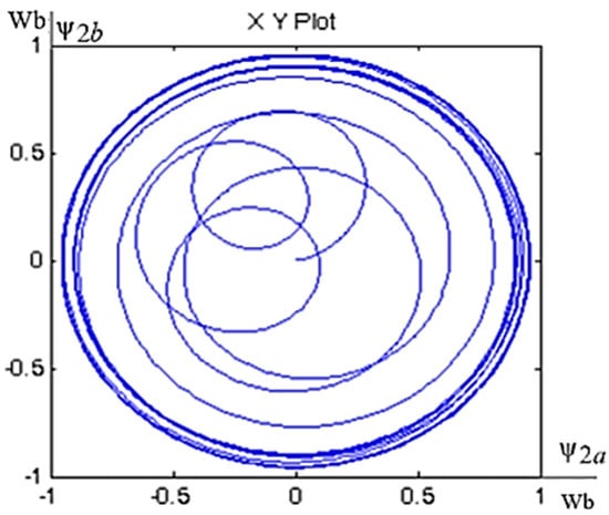
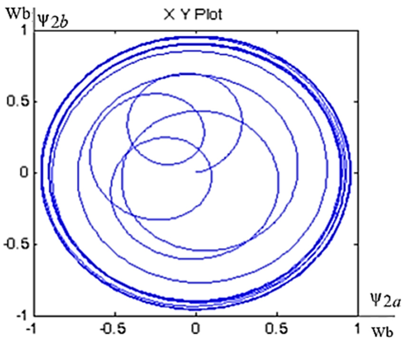
The developed induction motor model makes it possible to analyze additional electromechanical variables, including the transient responses of the rotor current components i2a, i2β, the stator flux-linkage components ψ1a, ψ1β, and the rotor flux-linkage components ψ2a, ψ2β. Furthermore, the model enables the construction of phase portraits describing the evolution of the rotating magnetic field generated by the stator and rotor windings. These graphical representations provide valuable insight into the electromagnetic processes occurring within the machine and facilitate the analysis of its dynamic behavior (Figure 8) [8].
Figure 8.
Phase portrait of the rotor magnetic field space vector in the stationary (α–β) reference frame.
The obtained dynamic mechanical characteristics demonstrate that the peak starting torque of the induction motor can reach values up to four times greater than the rated torque derived from the steady-state mechanical characteristic. Such transient torque peaks may generate significant mechanical stresses within the motor and transmission system, potentially affecting equipment durability, operational reliability, and service life.
Consequently, further research should be directed toward the analysis of induction motor starting transients employing thyristor-based soft-start systems. These devices provide a means of limiting inrush currents and reducing transient torque peaks, thereby improving the electromechanical performance of the drive system and decreasing the mechanical loading of critical drivetrain components during startup.
The analysis of the transient responses of stator current I[A], angular speed ω [rad/s] and electromagnetic torque M [N·m] confirmed the dynamic stability of the induction motor model parameterized using the obtained equivalent circuit parameters. The absence of unstable oscillations and the convergence of the system variables to their steady-state values indicate stable behavior of the simulated system under the considered operating conditions. Consequently, the identified parameter set can serve as a basis for further investigations, including the development, analysis, and tuning of advanced control systems for induction motor drive applications.
The simulation model developed in the MATLAB environment is capable of representing the transient operating conditions of the squirrel-cage induction motor and can be used for the investigation of its dynamic and electromechanical behavior. The obtained results demonstrate the applicability of the developed model for the analysis of transient processes and the evaluation of motor performance under various operating conditions.
In many induction motor simulation studies, the use of a full-order model is not always necessary, as certain state variables do not contribute directly to the analysis of the transient phenomena under consideration. Consequently, reduced-order or simplified models may be adopted to investigate the dynamic operating behavior of the motor while decreasing computational burden and improving simulation efficiency. Such models often provide an appropriate balance between modeling accuracy and computational complexity for engineering applications [8].
3. Results and Discussion
Contemporary electric drive control systems are typically based on the mathematical representation of the machine in the synchronously rotating (d)–(q) reference frame introduced by Robert H. Park. The Park transformation converts the three-phase (a, b, c) variables into an equivalent two-axis (d, q) coordinate system aligned with the rotating magnetic field. As a result, the originally time-varying machine equations are transformed into a more tractable form, thereby simplifying the analysis of electromagnetic processes and enabling the development of control algorithms for electric drives.
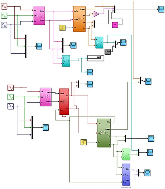
The three-phase stator variables (a, b, c) are transformed into the stationary (α, β) reference frame through the Clarke transformation and then into the synchronously rotating (d, q) reference frame by means of the Park transformation. This sequence of coordinate transformations simplifies the mathematical representation of the induction motor by converting the time-varying three-phase quantities into equivalent two-axis variables. Consequently, the motor equations in the rotating reference frame can be implemented in the simulation model presented in Figure 9.
Figure 9.
MATLAB/Simulink implementation of the induction motor model in the synchronously rotating (d)–(q) reference frame.
The current characteristics indicate that the magnitudes of the current vectors and remain equivalent in the considered coordinate systems. This demonstrates the consistency of the induction motor representation in both the stationary (α)–(β) and rotating (d)–(q) reference frames. By applying the inverse coordinate transformation, the rotating-frame current components and can be transformed into the stationary-frame components and . Furthermore, using Euler’s formula, the current space vector can be expressed through its projections onto the real and imaginary axes as follows (9) [9].
The transformation from the stationary (X)–(Y) reference frame to the rotating (d)–(q) reference frame is performed using the direct Park transformation,
It follows that
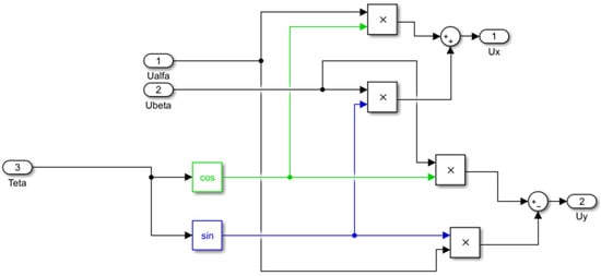
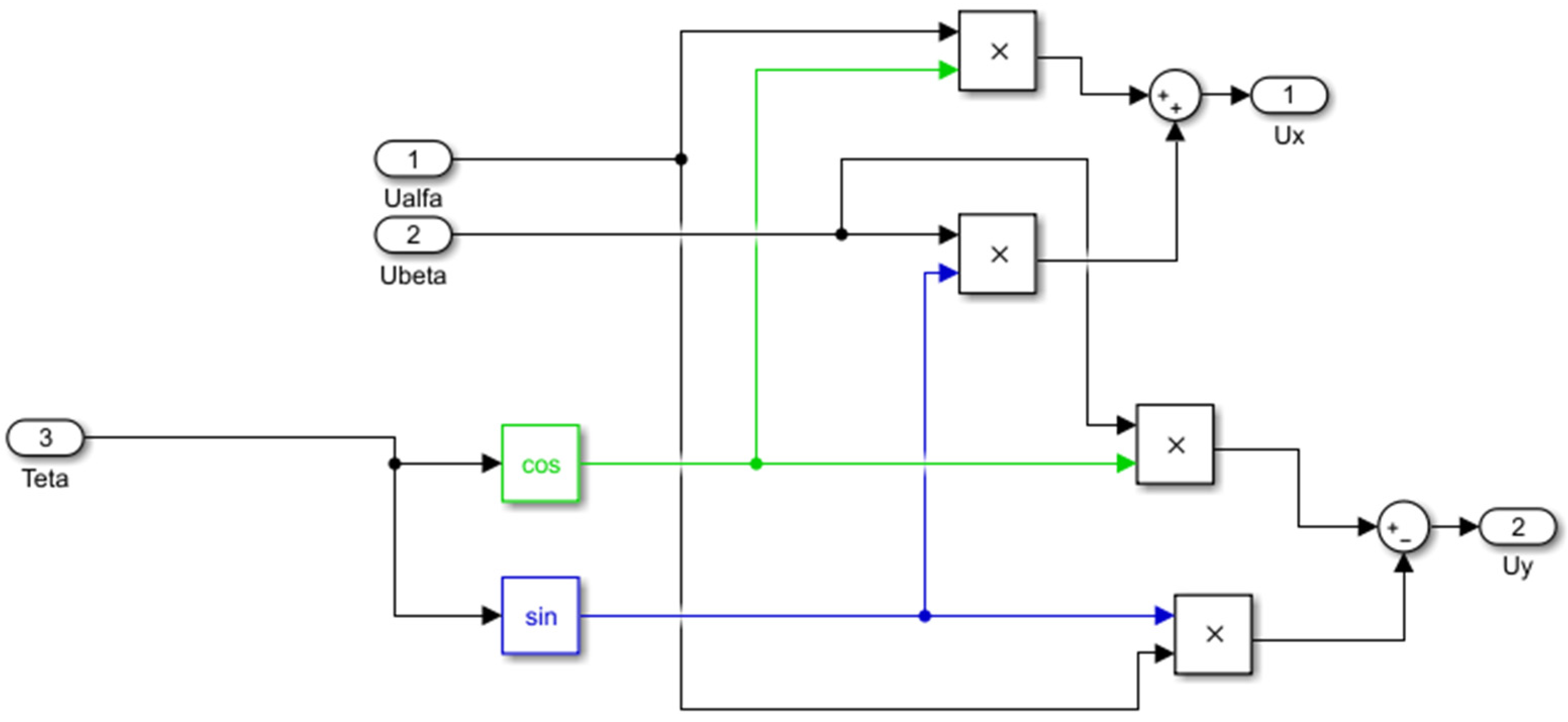
Figure 10 presents the Park transformation block applied to the voltage variables. This behavior confirms the effectiveness of the coordinate transformation in converting sinusoidal three-phase quantities into quasi-constant variables suitable for control system analysis and design.
Figure 10.
Implementation of the Park transformation in the simulation model.
The analysis of the current characteristics demonstrates that the magnitudes of the current vector components and remain unchanged when expressed in either the stationary or rotating reference frame (Figure 13). This confirms the consistency of the coordinate transformations and indicates that the dynamic behavior of the induction motor can be accurately represented in both coordinate systems. Consequently, either formulation may be employed for simulation and control-system analysis, depending on the specific objectives of the study.
The comparison of the obtained speed characteristics demonstrates that the motor speed response remains unchanged when represented in either the stationary or the rotating reference frame. This result confirms the consistency of the coordinate transformations and provides additional numerical verification of the developed induction motor model. In the synchronously rotating (d)–(q) reference frame, the voltage components are transformed into constant or slowly varying quantities under steady-state operating conditions. This feature constitutes one of the advantages of the Park transformation and provides a convenient framework for the implementation of control systems. By contrast, in the stationary (α–β) reference frame, the corresponding variables remain sinusoidal and time-varying, making the direct evaluation of control errors more challenging. In such cases, both amplitude deviations and phase shifts must be considered simultaneously. The representation of electrical variables as quasi-constant quantities in the rotating reference frame significantly simplifies controller design, feedback processing, and the implementation of vector-control strategies for induction motor drives.
A potential drawback of the considered approach is the increase in the time required for the overall control system to achieve steady-state operation. In certain cases, this may affect the transient response and stability margins of the closed-loop system. Despite this limitation, the representation of electrical variables as constant or quasi-constant quantities in the rotating (d)–(q) reference frame provides significant advantages for control-system design. In particular, it enables the direct application of classical control theory techniques, including the systematic tuning and optimization of control loops based on constant reference signals. This simplifies controller synthesis and facilitates the implementation of vector-control strategies for induction motor drives.
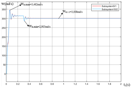
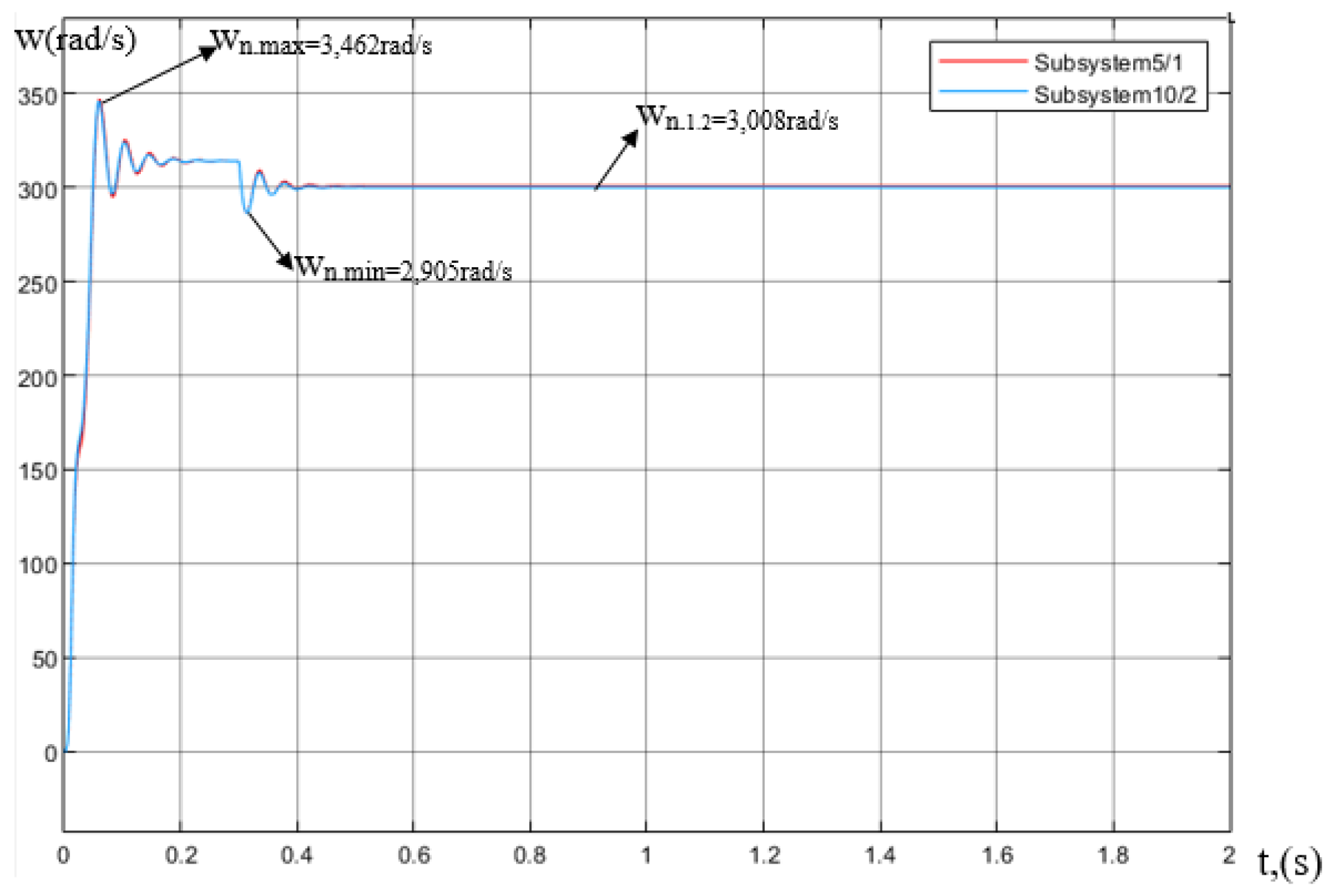
To validate the consistency of the developed mathematical formulations, the simulation results obtained from the induction motor model in the stationary reference frame (Figure 1) were compared with those produced by the model implemented in the rotating (d)–(q) reference frame (Figure 9). The corresponding angular speed responses (wn) are presented in Figure 11. The comparison enables an assessment of the equivalence of the two coordinate representations and provides additional verification of the developed simulation models.
Figure 11.
Comparison of the speed characteristics (wn) in the stationary and rotating reference frames.
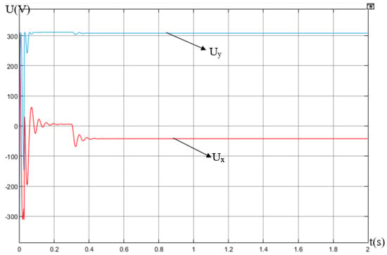
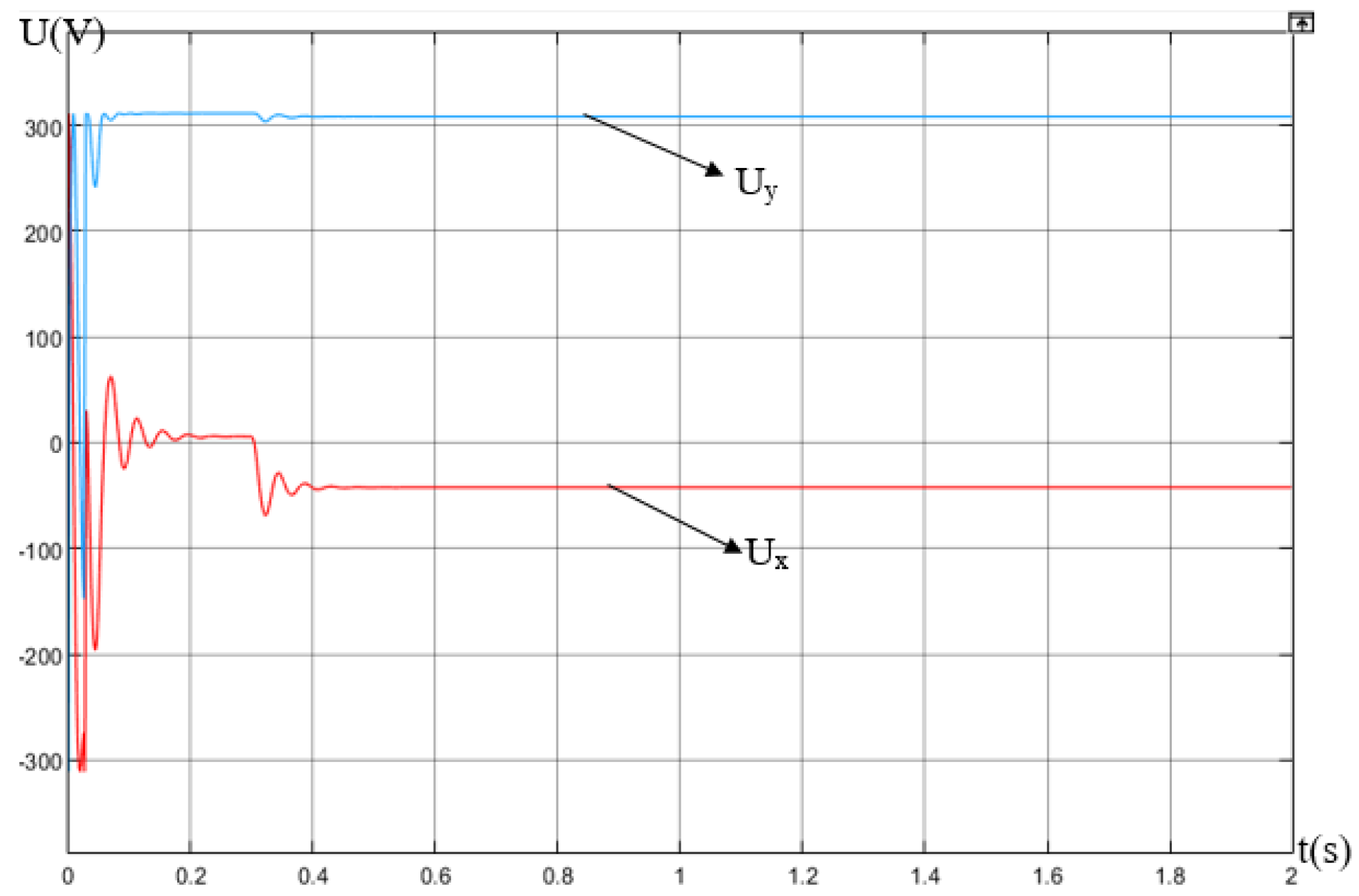
The resulting voltage components and , expressed in the rotating reference frame, exhibit constant steady-state values, as illustrated in Figure 12.
Figure 12.
Voltage components Ux and Uy in the rotating reference frame obtained through the Park transformation.
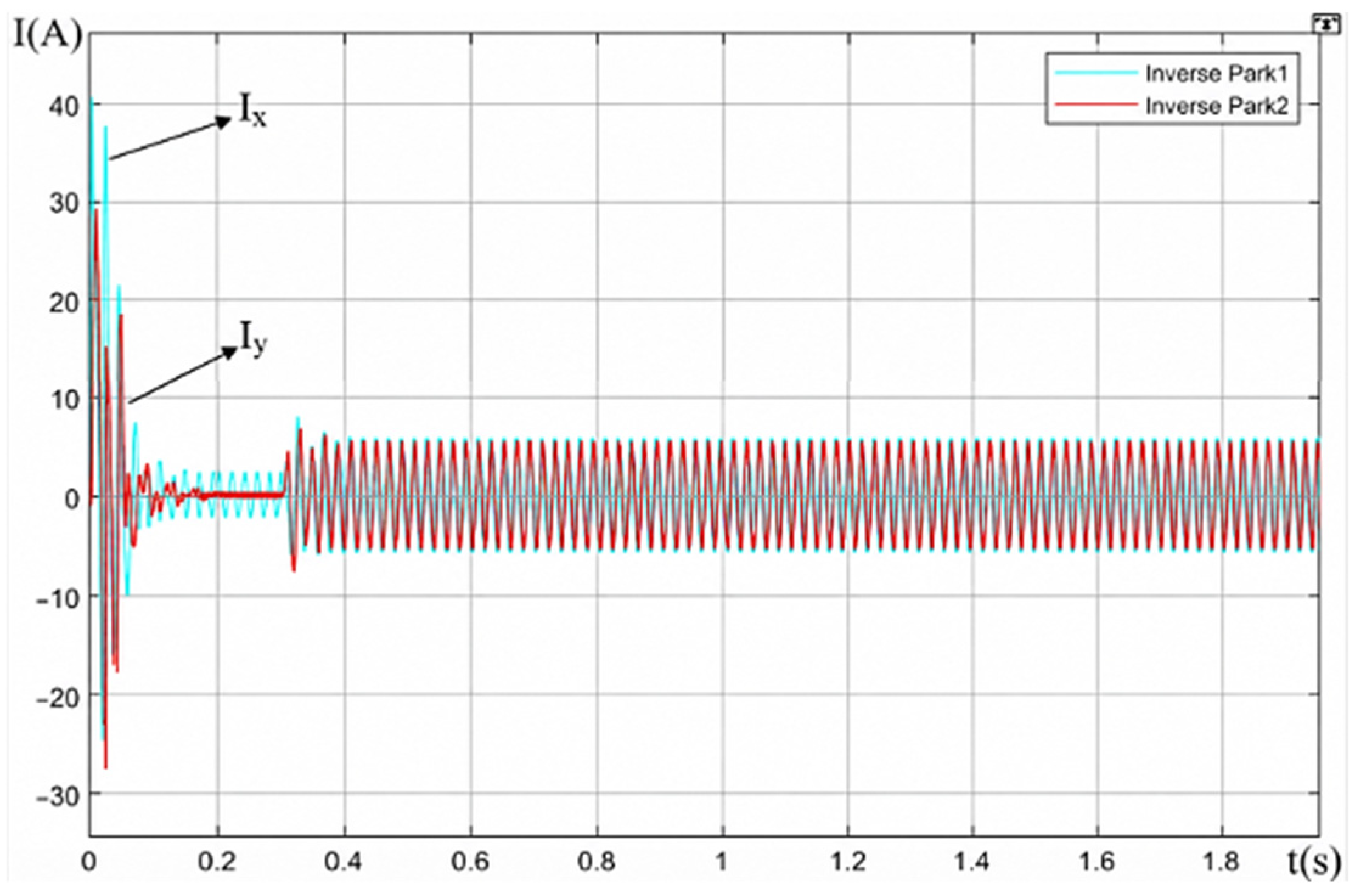
Figure 13.
Current components Ix and Iy in the rotating (x)–(y) reference frame obtained through the Park transformation.
The characteristics presented in Figure 3 indicate that the traction load imposes a high torque demand at low rotational speeds, which may hinder the direct starting capability of the induction motor. To overcome this limitation, a variable-frequency drive (VFD) is utilized to implement frequency control during the startup process. By regulating the supply frequency and voltage, the drive system can control the electromagnetic torque developed by the motor, thereby reducing mechanical and electrical stresses while ensuring smooth, controlled, and reliable acceleration from standstill [10].
3.1. Electric Drive Control System
This study investigates the performance of a variable-frequency drive system employing the VFD–IM configuration, consisting of a variable-frequency drive (VFD) and an induction motor (IM). The control strategy is based on frequency regulation principles, which determine the relationship between the supply frequency and the operating conditions of the motor.
The corresponding frequency-control laws are given by Equation (10):
Before conducting the simulations, the MATLAB/Simulink environment was configured and the numerical solver settings were selected in accordance with the requirements of the developed model. Following this procedure, the variable-frequency drive (VFD) system model was implemented, and the phase voltage waveforms were measured and analyzed to verify the correct operation of the converter.
The conventional scalar control strategy based on the constant voltage-to-frequency ratio (U/f = const) was selected for the following reasons:
- −
- Simplicity of implementation and parameter tuning;
- −
- Lower computational requirements compared with vector control and Direct Torque Control (DTC);
- −
- High reliability and widespread industrial application in low- and medium-power drive systems;
- −
- Sufficient control accuracy for agricultural electric vehicle applications, which generally operate under moderate dynamic performance requirements;
- −
- Consistency with the objective of the present study, which is focused on the development and investigation of a mathematical model of a traction electric drive rather than on a comparative analysis of control algorithms [11].
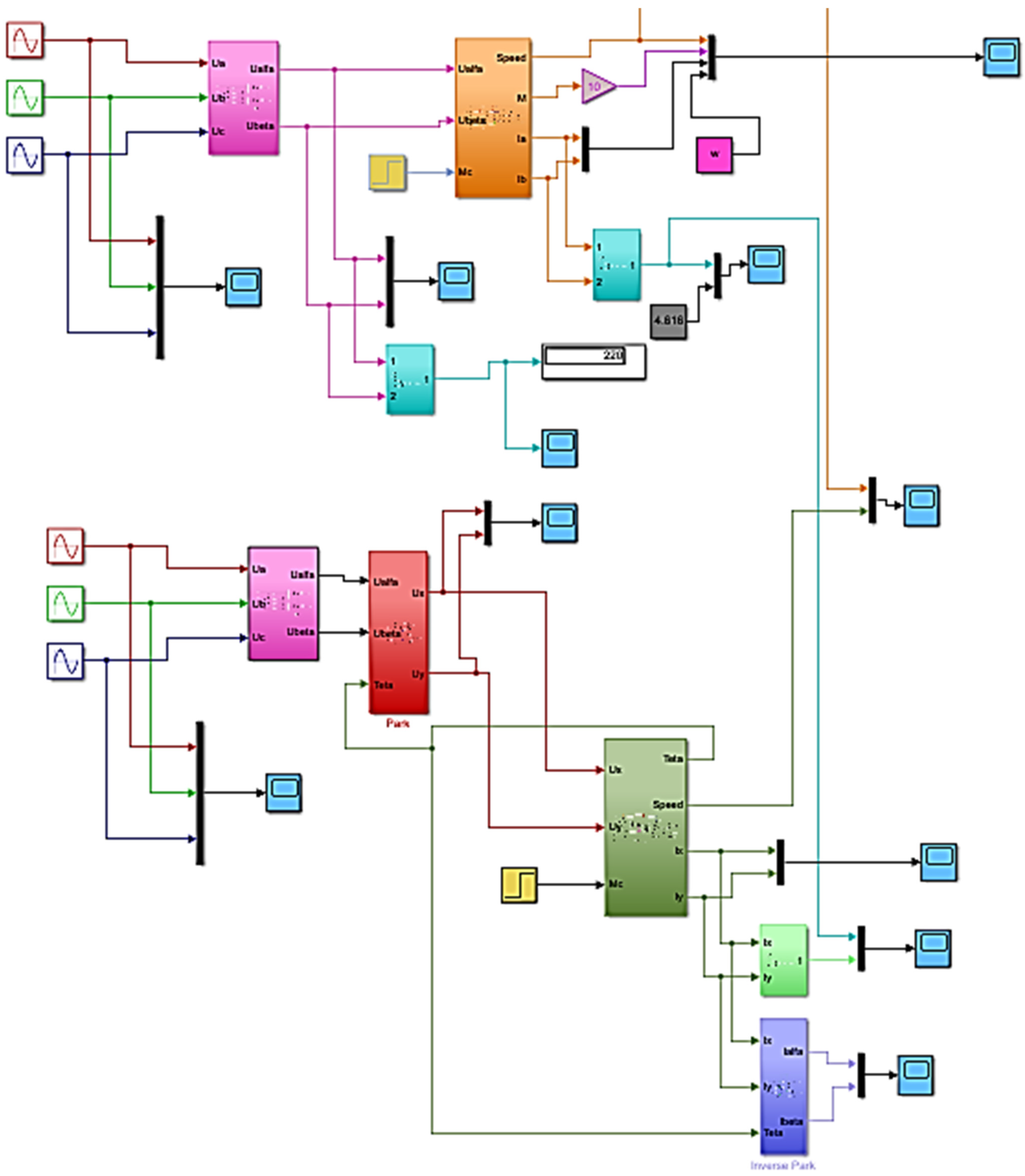
In practical variable-frequency drive systems, direct measurement of phase voltages is often challenging because the inverter output does not typically provide an accessible neutral reference point. To facilitate voltage analysis within the simulation environment, an artificial neutral point was introduced into the model. This approach enabled the measurement and evaluation of the phase voltage waveforms, as illustrated in Figure 14.
Figure 14.
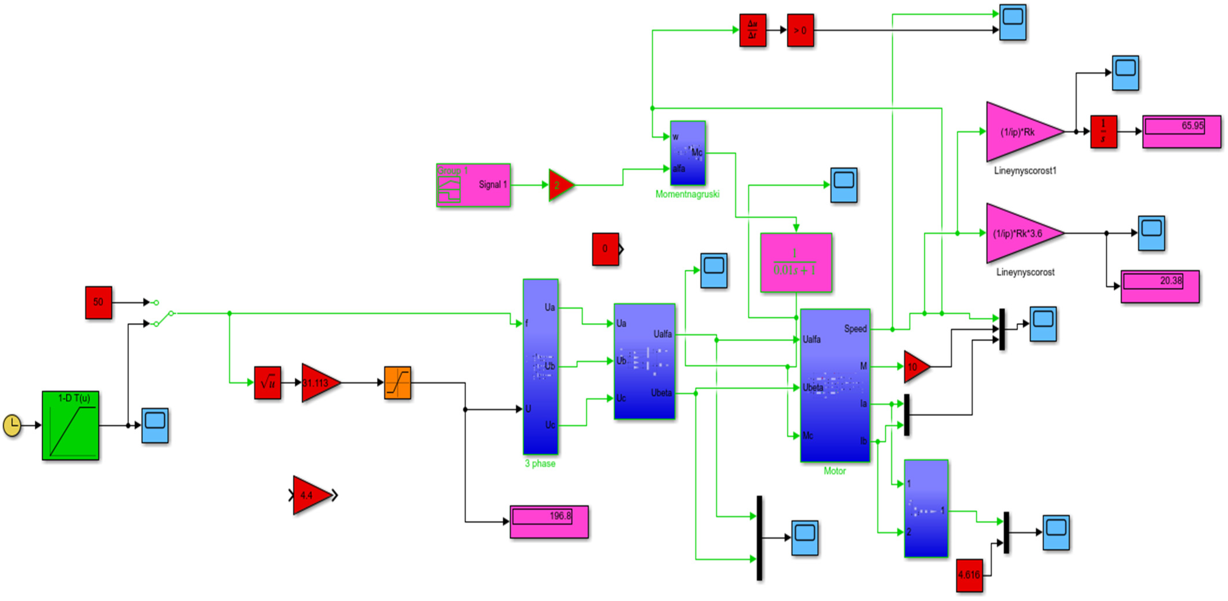
Simulation model of the variable-frequency drive–induction motor (VFD–IM) system. Figure 15 illustrates the simulation model of the variable-frequency drive (VFD) subsystem. The VFD is responsible for converting the fixed-frequency utility supply (50 Hz) into a three-phase voltage with controllable frequency and amplitude, thereby enabling speed regulation of the induction motor. The conversion process comprises two stages: an AC–DC rectification stage, which converts the grid voltage into a DC-link voltage, followed by a DC–AC inversion stage, which generates a three-phase output voltage of the desired frequency and magnitude. The subsystem receives the frequency reference (f), voltage reference (U), and control signals as inputs, while its outputs are the three-phase voltages—Ua, Ub, Uc which are applied to the stator windings of the induction motor.
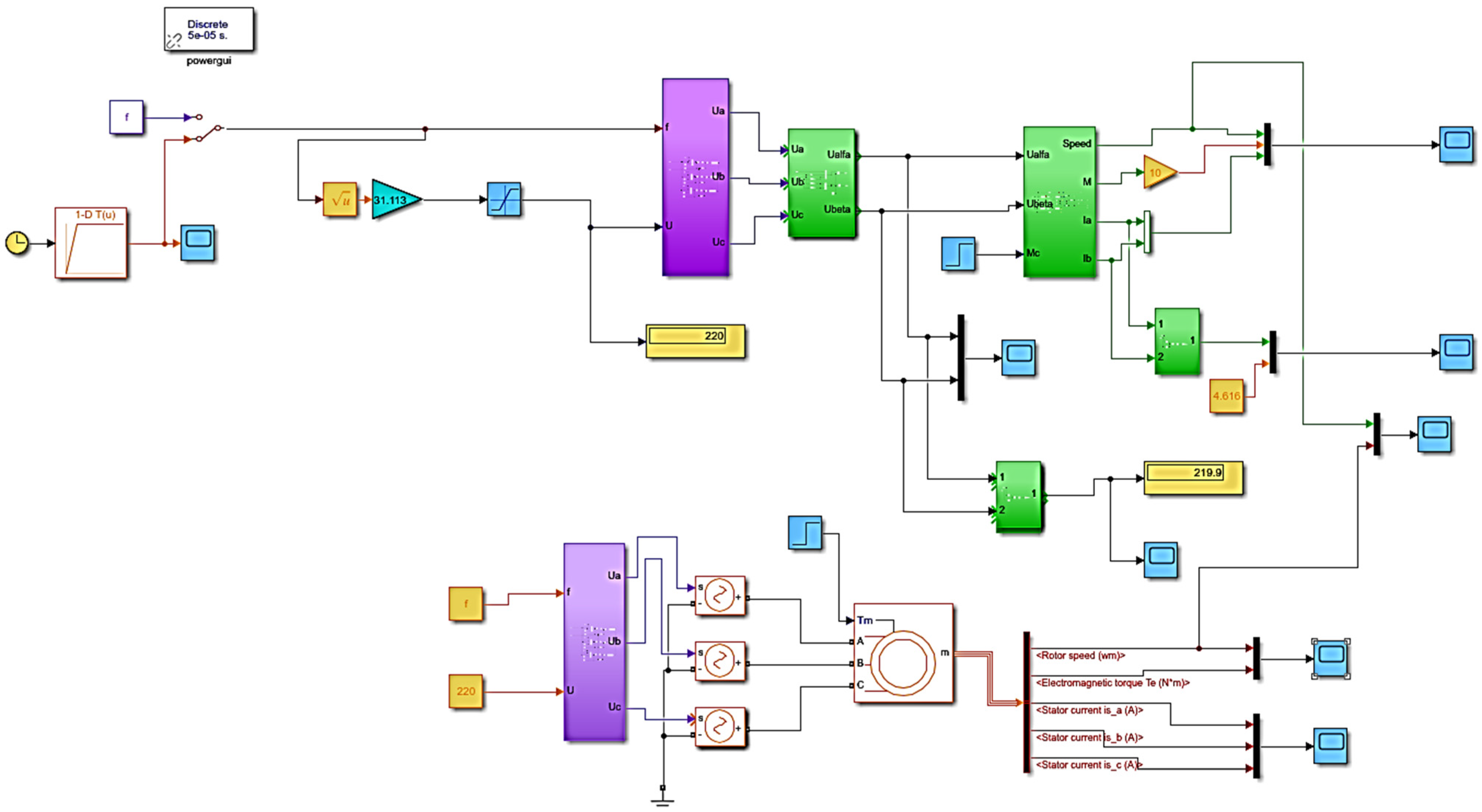
Figure 15.
Simulation model of the variable-frequency drive (VFD) subsystem.
The mathematical representation of the induction motor under steady-state operating conditions can be obtained from the following set of Equation (11):
where (ω) denotes the angular frequency of the rotating magnetic field, corresponding to the synchronous electrical angular frequency of the rotor. The steady-state operating conditions can therefore be described by the following system of algebraic Equation (12) [12]:
Figure 14 illustrates the simulation model of the variable-frequency drive–induction motor (VFD–IM) system. The model constitutes a comprehensive mathematical and computational representation of the electric drive and provides a framework for analyzing the dynamic behavior of the induction motor under variable operating conditions. By regulating the frequency of the supply voltage, the system enables effective control of both the motor speed and electromagnetic torque, thereby facilitating the investigation of drive performance and control strategies.
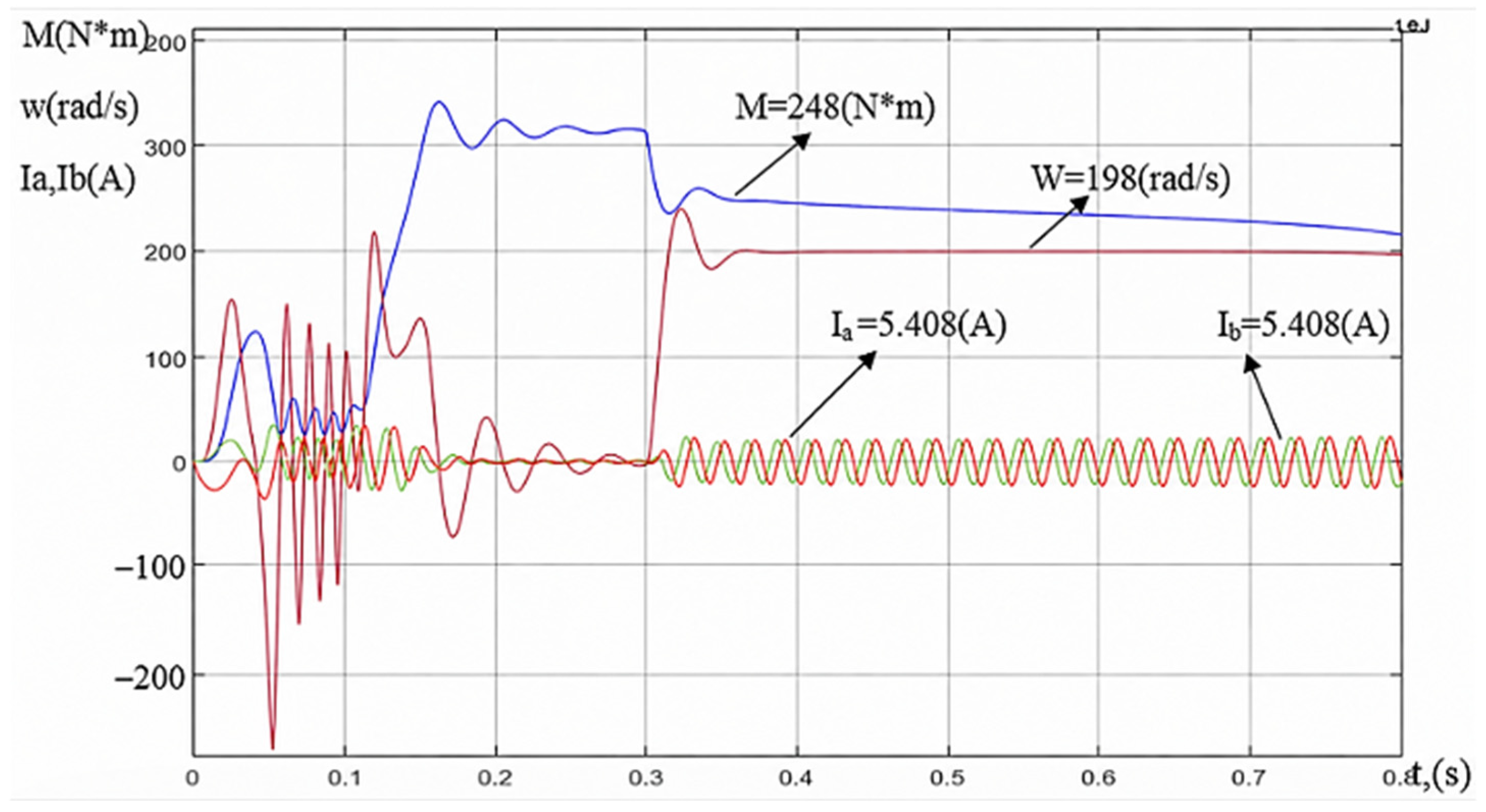
Figure 16 presents the transient responses of the electromagnetic torque (M), angular speed (ω), and phase currents Ia, Ib during the startup of the variable frequency drive (VFD)–induction motor (IM) system.
Figure 16.
Transient responses of electromagnetic torque (M), angular speed (w) and currents (Ia, Ib).
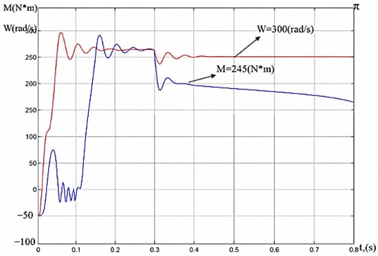
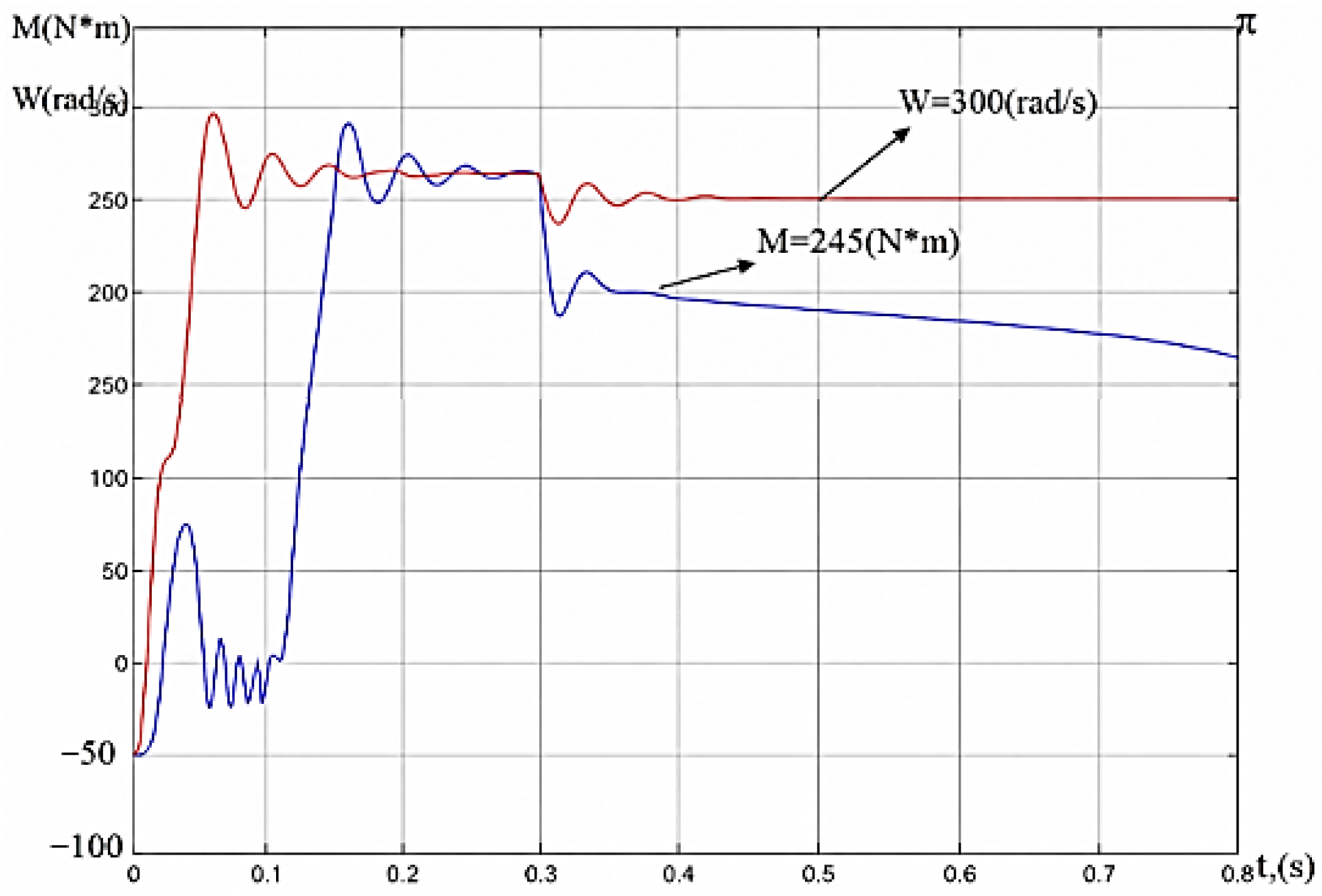
The transient angular speed responses of the two induction motors (IMs) are presented in Figure 17.
Figure 17.
Comparison of the angular speed (w) transient responses of two induction motors under identical operating conditions.
3.2. Load Characteristic
Owing to its electromechanical characteristics, an electric motor can deliver significantly higher traction torque at low vehicle speeds than a conventional internal combustion engine. Furthermore, electric drives provide a broad speed-control range and support regenerative braking, allowing a portion of the vehicle’s kinetic energy to be recovered during deceleration. Another important advantage is that, unlike internal combustion engines, electric motors do not require continuous operation when the vehicle is stationary, thereby eliminating idle losses and contributing to improved overall energy efficiency [13].
The utilization of these characteristics can support the development of compact, energy-efficient, and environmentally sustainable electric vehicles. Consequently, the traction electric drive represents a critical subsystem whose performance directly affects the operational efficiency, reliability, and dynamic behavior of the vehicle. Therefore, a traction electric drive is required to satisfy the following key technical and operational requirements [14]:
- −
- The ability to accurately reproduce the required traction characteristics of the electric vehicle over the entire operating range of tractive effort and vehicle speed;
- −
- High energy efficiency across the full operating range, including conditions corresponding to maximum tractive effort and maximum speed;
- −
- Operation in regenerative braking mode, enabling the recovery of kinetic energy;
- −
- Low mass and compact dimensions to improve the overall performance and energy efficiency of the vehicle;
- −
- Economic viability, including reasonable manufacturing and operating costs.
The traction characteristic of an electric vehicle is defined as the relationship between the tractive force generated at the driving wheels and the vehicle speed. Accurate realization of this characteristic requires coordinated control of the angular speed and electromagnetic torque of the traction electric motor (TEM) within the drive control system. Such control ensures that the vehicle can meet the required performance demands over the entire operating range of speed and tractive effort.
The steady-state mechanical characteristic of the traction motor in a controlled drive system represents one of the most important design factors affecting the selection and sizing of the machine. In particular, the rated electromagnetic torque has a direct influence on the motor dimensions, active material requirements, and overall mass. Consequently, the mechanical characteristic plays a crucial role in determining both the performance capabilities and the physical configuration of the traction motor [15,16].
To analyze the performance of the traction induction motor in an electric vehicle, a load torque modeling subsystem was developed in the MATLAB/Simulink environment. The proposed model calculates the resisting torque acting on the motor shaft as a function of vehicle operating conditions, rotor angular speed, and external road-load factors. The load characteristic constitutes a key component of traction drive analysis, as it defines the torque demand imposed on the motor and determines the operating conditions required to maintain stable vehicle motion across a wide range of driving scenarios. Consequently, accurate representation of the load characteristic is essential for evaluating drive performance, energy efficiency, and control-system effectiveness [17] (Figure 18).
Figure 18.
Load–traction characteristic of the VFD–IM system.
In the proposed modeling framework, the load torque applied to the induction motor shaft is determined from the combined contribution of the primary vehicle road-load components. These components include rolling resistance, grade resistance associated with road inclination, and aerodynamic drag. Together, these forces define the external mechanical load acting on the traction drive and significantly influence the vehicle’s dynamic and energy performance [18].
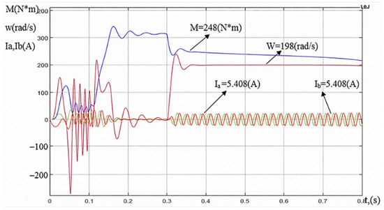
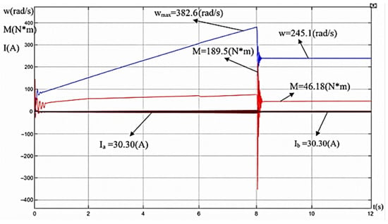
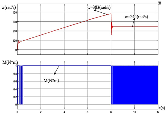
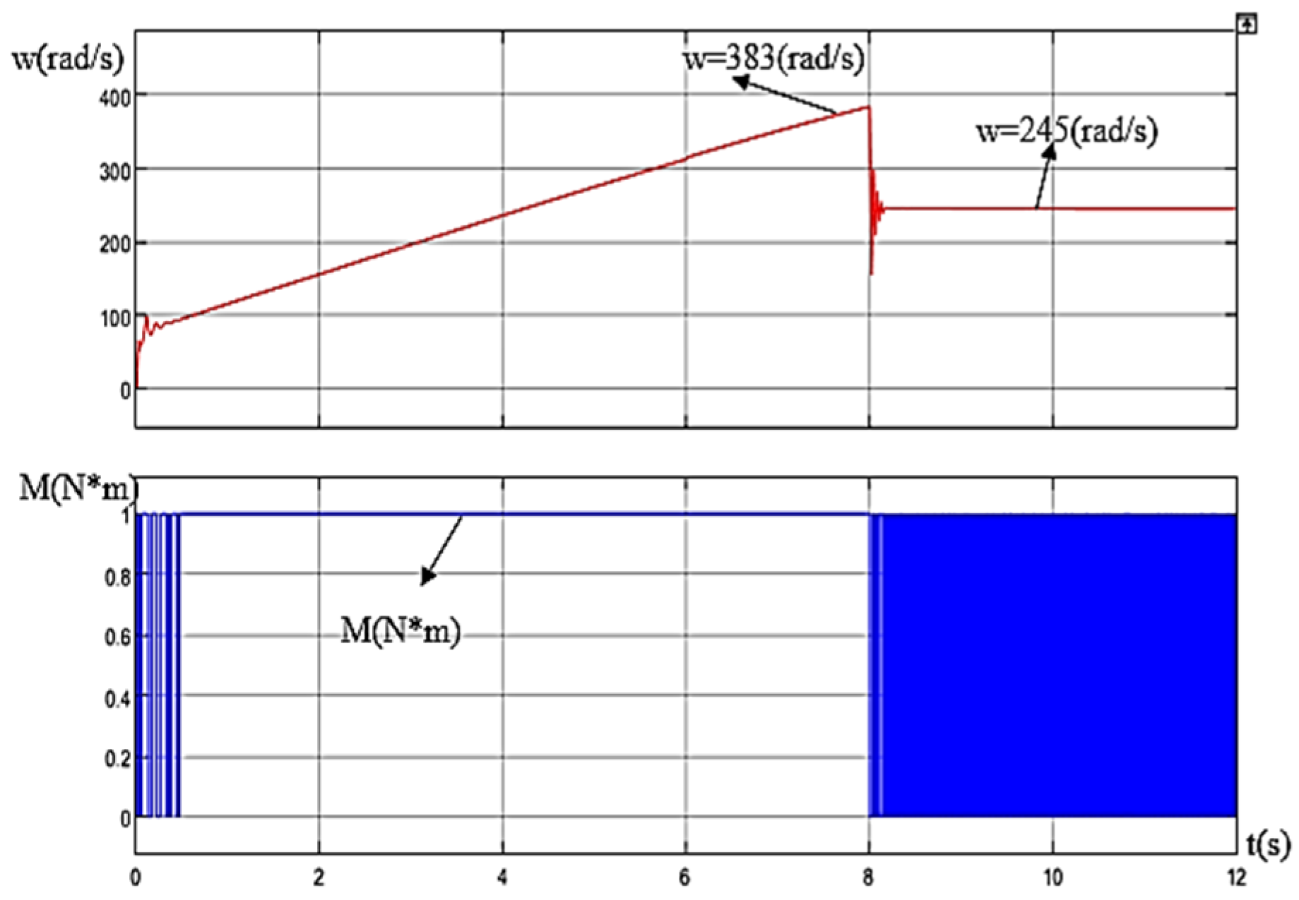
The simulation results obtained from the developed load–traction model of the variable-frequency drive–induction motor (VFD–IM) system are presented in Figure 19. The figure illustrates the dynamic responses of electromagnetic torque (M), angular speed (ω), and stator current components (Ia, Ib) under varying load conditions. Figure 20 presents the corresponding load characteristic, showing the dependence of the motor angular speed (ω) on the applied load torque (Ms). These characteristics provide insight into the operating behavior of the traction drive and its ability to maintain stable performance under changing mechanical loads.
Figure 19.
Dynamic responses of electromagnetic torque (M), angular speed (w), and current components (Ia, Ib).
Figure 20.
Load characteristic showing the relationship between angular speed (w) and load torque (Mc).
The obtained load characteristic illustrates the relationship between the load torque demand and the operating conditions of the electric vehicle, including vehicle speed and external road-load factors. During the acceleration period, the traction motor develops a peak electromagnetic torque of—, enabling the vehicle to attain a maximum angular speed of—. As the transient response decays, the drive system converges to a steady-state operating point corresponding to an angular speed of— and an electromagnetic torque of— (Figure 20). These values characterize the stable equilibrium condition of the traction drive and confirm its capability to maintain the required operating regime under the applied mechanical load [18].
The characteristic further indicates phase current values of and—.
- −
- The identical magnitudes of the phase currents confirm the symmetrical operating conditions of the machine in steady state.
- −
- This behavior indicates balanced motor operation and demonstrates that the electromechanical system reaches a stable equilibrium following the transient response.
- −
- The absence of current asymmetry further suggests the correct functioning of both the power converter and the induction motor model under the considered operating conditions (Figure 19).
The obtained results indicate that the developed model is capable of representing the load characteristics of the traction induction motor employed in the electric vehicle. The proposed modeling framework enables the identification of both nominal and limiting operating conditions, facilitates the evaluation of the compatibility between motor characteristics and vehicle operating requirements, and provides valuable insight into the dynamic behavior of the traction drive system. Consequently, the model constitutes an effective tool for traction drive design, motor parameter selection, and the assessment of the energy efficiency and operational performance of electric vehicles [19].
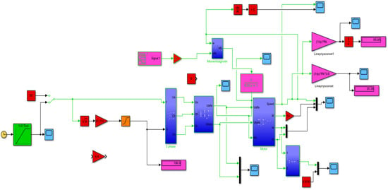
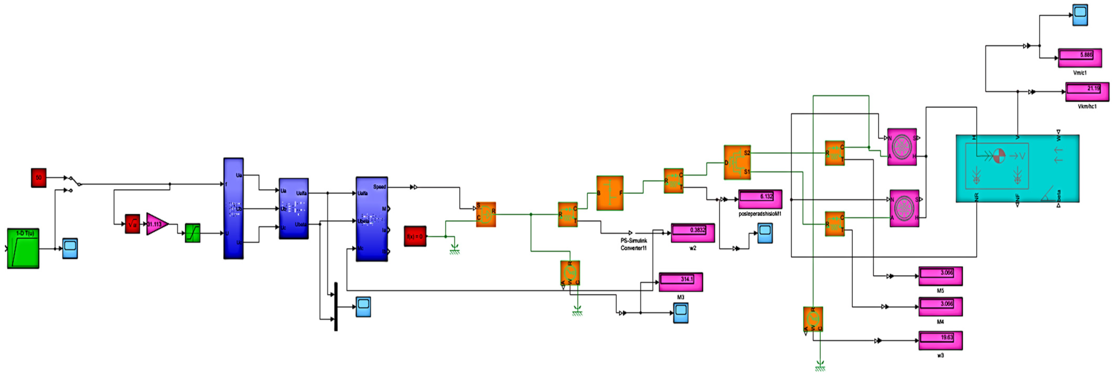
The developed simulation model of the variable-frequency drive–induction motor (VFD–IM) electric vehicle system provides a comprehensive mathematical and computational representation of the traction propulsion system. The model integrates the variable-frequency drive, induction motor, and vehicle dynamics subsystem into a unified framework capable of describing the coupled electrical and mechanical processes occurring during vehicle operation. In addition to the internal drive dynamics, the model accounts for external factors, including road-load resistance, vehicle mass, and varying road conditions. Consequently, the proposed framework enables detailed analysis of vehicle acceleration and deceleration performance, energy consumption, traction capability, and overall drive-system efficiency under a wide range of operating scenarios (Figure 21).
Figure 21.
Integrated simulation model of the variable-frequency drive–induction motor (VFD–IM) traction system and electric vehicle dynamics.
Table 6 summarizes the structural components and corresponding subsystem descriptions of the electric vehicle incorporated into the development of the integrated simulation model of the “variable-frequency drive–induction motor–electric vehicle” system. These elements collectively define the vehicle dynamics and operating conditions considered in the simulation study [20].
Table 6.
Names of electric vehicle model blocks.
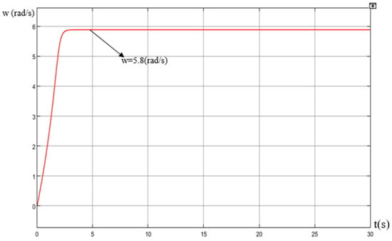
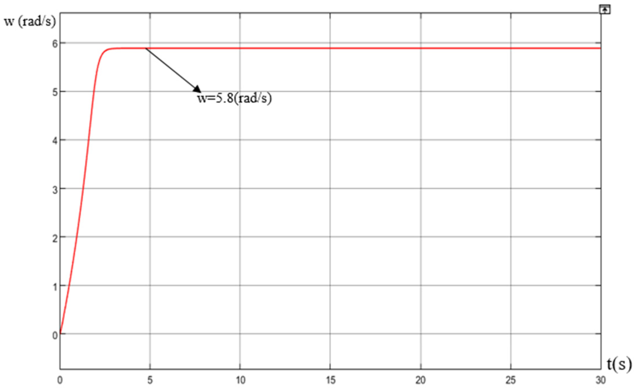
Figure 22 illustrates the transient speed (w) response of the electric vehicle.
Figure 22.
Illustrates the transient speed (w) response of the electric vehicle.
In the developed MATLAB/Simulink model, the induction motor was connected to an ideal voltage source, and the motor shaft rotation was transmitted to a mechanical load system. The angular velocity and load torque were continuously monitored, while torque sensors installed on both the motor shaft and the driven mechanism shaft provided feedback to the motor control system. This configuration enabled an accurate evaluation of the electromechanical dynamics of the drive system under operating conditions.
The simulation results presented in Figure 22 demonstrate that the electric vehicle starts moving at a speed of approximately , which fully corresponds to the predictions of the developed mathematical model. The close agreement between the calculated and simulated results confirms the validity of the proposed mathematical model and indicates that the selected control strategy and parameters of the induction motor have been correctly designed and matched.
Furthermore, the analysis of the transmission system revealed a significant torque amplification effect due to the gearbox. Before the gearbox, the motor shaft torque was only . After applying the selected transmission ratio of 16:1, the output torque increased to , representing a sixteen-fold increase in accordance with theoretical expectations. This result confirms that the selected transmission ratio effectively converts the high-speed, low-torque output of the induction motor into the higher torque required for vehicle traction.
From a practical perspective, this finding is particularly important for agricultural electric vehicles, which frequently operate under high-resistance conditions such as soft soil, uneven terrain, and loaded transportation tasks. The obtained torque multiplication ensures sufficient tractive capability while maintaining the use of a relatively low-power motor, thereby improving overall energy efficiency and reducing system cost. Consequently, the simulation results not only validate the proposed mathematical model but also demonstrate the feasibility of the developed electric drive system for agricultural vehicle applications [21,22].
4. Conclusions
The present study investigated approaches to improving the efficiency of the traction electric drive of an agricultural electric vehicle operating under variable load conditions characteristic of agricultural applications. The results indicate the potential applicability of a low-power induction motor (2–2.2 kW) as a traction drive due to its reliability, economic viability, robustness, and relatively simple construction. These characteristics make induction motor drives a promising solution for agricultural electric vehicle applications operating under demanding service conditions.
The analysis of transient processes in the stationary (α–β) reference frame for the 4A80V2U3 squirrel-cage induction motor demonstrated stable simulation responses with respect to the principal variables, including stator current, angular speed, and electromagnetic torque. The obtained equivalent circuit parameters were found to be consistent with the adopted mathematical formulation and may be used for further investigations of dynamic operating modes and control-system development for induction motor drives.
The developed MATLAB-based simulation model provides a useful framework for analyzing the transient behavior and dynamic performance of induction motor drive systems. In addition, the investigation of the variable-frequency drive–induction motor (VFD–IM) configuration operating under the conventional (U/f = const) control strategy demonstrated stable operation of the simulated drive system throughout the considered operating range.
The developed electric vehicle drive model showed that, for the adopted design parameters, the selected traction motor is capable of generating sufficient tractive effort to propel the vehicle and achieve a maximum speed of approximately . The obtained results are consistent with the assumptions of the developed mathematical model and support the feasibility of the proposed traction drive configuration for agricultural electric vehicle applications.
It should be noted that the present study does not include experimental verification of the developed model. Therefore, the obtained results should be interpreted as evidence of the internal consistency and applicability of the proposed mathematical framework rather than as full experimental verification. Future work will focus on experimental verification of the model and quantitative comparison of simulation results with measured data obtained from a dedicated test bench.
Overall, the obtained results indicate the potential feasibility and practical applicability of the proposed traction electric drive architecture for agricultural electric vehicle applications. The developed modeling framework may serve as a basis for further research, design optimization, and experimental investigation of energy-efficient electric propulsion systems for agricultural transportation tasks.
Author Contributions
Conceptualization, E.D.; methodology, Z.S. and S.I.; software, A.B. and D.C.; numerical verification, G.T.; formal analysis, J.N.; investigation, G.N.; resources, Z.S. and S.I.; data curation, A.B. and D.C.; writing—original draft preparation, E.D., Z.S. and S.I.; writing—review and editing, E.D., Z.S. and S.I.; visualization, J.N.; supervision, E.D.; project administration, Z.S. and S.I.; funding acquisition, E.D., Z.S. and S.I. All authors have read and agreed to the published version of the manuscript.
Funding
This research received no external funding.
Data Availability Statement
The data presented in this study are available upon request from the corresponding author.
Conflicts of Interest
The authors declare no conflicts of interest.
References
- Epifanov, A.P.; Malaichuk, L.M.; Gushchinsky, A.G. Electric Drive; Lan: Saint Petersburg, Russia, 2022; 400p. [Google Scholar]
- Khamitov, R.N.; Okhotnikov, A.A.; Glazyrin, A.S. Automated Electric Drive; Omsk State Technical University: Omsk, Russia, 2022; 124p. [Google Scholar]
- Lisov, A.A.; Vozmilov, A.G. Electronic Differential System Based on Neural Networks for Electric Vehicles: Development, Adaptation and Prospects of Application. Mod. Transp. Syst. Technol. 2025, 11, 24–42. [Google Scholar] [CrossRef] [Scilit]
- Boldea, I.; Tutelea, L.N. Electric Machines: Transients, Control Principles, Finite Element Analysis, and Optimal Design with MATLAB; CRC Press: Boca Raton, FL, USA, 2022; 454p. [Google Scholar]
- Onishchenko, G.B.; Kalachev, Y.N. SimInTech: Control Systems and Electric Drive Modeling; DMK Press: Moscow, Russia, 2022; 154p. [Google Scholar]
- Goolak, S.; Liubarskyi, B. Analysis of the Efficiency of Traction Drive Control Systems of Electric Locomotives with Asynchronous Traction Motors. Energies 2023, 16, 3689. [Google Scholar] [CrossRef] [Scilit]
- Kodkin, V.; Anikin, A. Optimization of Traction Electric Drive with Frequency Control. World Electr. Veh. J. 2025, 16, 139. [Google Scholar] [CrossRef] [Scilit]
- Dinolova, P.; Ruseva, V.; Dinolov, O. Energy Efficiency of Induction Motor Drives: State of the Art, Analysis and Recommendations. Energies 2023, 16, 7136. [Google Scholar] [CrossRef] [Scilit]
- Darkenbaeva, E.; Balbaev, G. Optimization of Control System Components of Asynchronous Electric Traction Drive. Bull. KazATK 2023, 124, 384–396. [Google Scholar] [CrossRef] [Scilit]
- Mahmoud, A.G.; Abdelaziz, A.Y.; Diab, Z.M.Z. Comprehensive Examination of Vector-Controlled Induction Motor Drive Techniques. Energies 2023, 16, 2854. [Google Scholar] [CrossRef] [Scilit]
- Azab, M. A Review of Recent Trends in High-Efficiency Induction Motor Drives. Machines 2025, 7, 15. [Google Scholar] [CrossRef] [Scilit]
- Saushev, A.V.; Belousov, I.V.; Bova, E.V.; Rumyantsev, A.Y. Incomplete-phase algorithms for pulse-width modulation of three-phase voltages in frequency control systems of electric drives. Mod. Transp. Syst. Technol. 2024, 10, 231–246. [Google Scholar] [CrossRef] [Scilit]
- Kuznetsov, A.Y.; Ponurovsky, V.A. Frequency-Controlled Induction Electric Drive with Pulse-Width Modulation and Operating Mode Identification. Vestn. Altai. State Agrar. Univ. 2024, 7, 77–84. [Google Scholar] [CrossRef] [Scilit]
- Assadian, F.; Martin, G. Review of Model Predictive Control and Other Methodologies for Lateral Control of an Autonomous Vehicle; IntechOpen: London, UK, 2023. [Google Scholar] [CrossRef] [Scilit]
- Das, R.K.; Hossain, A.M. Vehicle Dynamics, Lateral Forces, Roll Angle, Tire Wear and Road Profile States Estimation—A Review. Eng. Model. 2022, 35, 65–89. [Google Scholar] [CrossRef] [Scilit]
- Gobbi, M.; Sattar, A. Traction motors for electric vehicles: Maximization of mechanical efficiency—A review. Appl. Energy 2024, 357, 122496. [Google Scholar] [CrossRef] [Scilit]
- Kebbati, Y.; Ait-Oufroukh, N. Lateral control for autonomous wheeled vehicles: A technical review. Asian J. Control 2022, 25, 2539–2563. [Google Scholar] [CrossRef] [Scilit]
- Komnos, D.; Broekaert, S.; Grigoratos, T.; Ntziachristos, L.; Fontaras, G. In Use Determination of Aerodynamic and Rolling Resistances of Heavy-Duty Vehicles. Sustainability 2021, 13, 974. [Google Scholar] [CrossRef] [Scilit]
- Van Greunen, R.; Oosthuizen, C. Data Driven Methods for Finding Coefficients of Aerodynamic Drag and Rolling Resistance of Electric Vehicles. World Electr. Veh. J. 2023, 14, 134. [Google Scholar] [CrossRef] [Scilit]
- Artuñedo, A.; Moreno-Gonzalez, M.; Villagra, J. Lateral control for autonomous vehicles: A comparative evaluation. Annu. Rev. Control 2024, 57, 100910. [Google Scholar] [CrossRef] [Scilit]
- Konev, V.V.; Karnaukhov, N.N.; Merdanov, S.h.M.; Polovnikov, E.V. Electric drive of road construction machines. Archit. Constr. Transp. 2022, 65–73. [Google Scholar] [CrossRef] [Scilit]
- Issenov, S.; Iskakov, R.; Tergemes, K.; Issenov, Z. Development of mathematical description of mechanical characteristics of integrated multi-motor electrical drive for drying plant. East.-Eur. J. Enterp. Technol. 2022, 1, 46–54. [Google Scholar] [CrossRef] [Scilit]



Disclaimer/Publisher’s Note: The statements, opinions and data contained in all publications are solely those of the individual author(s) and contributor(s) and not of MDPI and/or the editor(s). MDPI and/or the editor(s) disclaim responsibility for any injury to people or property resulting from any ideas, methods, instructions or products referred to in the content. |
© 2026 by the authors. Licensee MDPI, Basel, Switzerland. This article is an open access article distributed under the terms and conditions of the Creative Commons Attribution (CC BY) license.