


Abstract
Active disturbance rejection control (ADRC) has broad application prospects in permanent magnet synchronous motors (PMSMs) due to its advantages of being independent of the controlled object model, excellent adaptability, and strong anti-disturbance performance. When tuning the bandwidth (ω0) of ADRC, the anti-disturbance performance of the control system is improved with the increase in bandwidth, yet the noise suppression performance of the system is degraded. This trade-off restricts the selection of bandwidth and further impairs the dynamic performance of the system. To address this issue, this paper proposes a modified ADRC (MADRC) strategy based on a modified extended state observer (MESO). The MESO expands the differential terms of disturbances into new state variables. By conducting multi-layer observation of disturbances and their differential signals, the anti-disturbance performance of the system is enhanced while its noise suppression performance is maintained. Frequency-domain analysis of the MESO and the conventional extended state observer (ESO) demonstrates that the MESO achieves a stronger anti-disturbance performance in the low-frequency band, with its noise suppression performance remaining unchanged in the high-frequency band. Finally, experimental comparisons between the conventional ADRC and the proposed MADRC are carried out on a PMSM platform to verify the superiority of the proposed strategy.
1. Introduction
Permanent magnet synchronous motors (PMSMs) have been widely used in the aviation field due to their high-power density, high efficiency, and fast dynamic response [1,2,3]. In recent years, high-performance applications have also put forward higher requirements for the speed control of PMSM drives. Furthermore, as a nonlinear, strongly coupled, and time-varying complex system, PMSMs are subject to various disturbances, such as external perturbations (load torque variations) and internal perturbations (parameter deviations). This has made PMSM control technology a persistent research hotspot [4,5].
At present, the traditional proportional–integral–derivative (PID) controllers have been widely applied in industrial motor control systems. However, PID controllers cannot meet the requirements of both good reference tracking performance and pleasant disturbance rejection property [6]. Meanwhile, PID control is highly susceptible to changes in motor parameters and exhibits poor parameter adaptability. When operating conditions change, parameters need to be readjusted to ensure the quality of closed-loop dynamic performance [7,8].
To improve the system immunity, researcher Han proposed the active disturbance rejection control (ADRC) strategy based on the concept of traditional PID control [9]. ADRC attributes all uncertainties of the controlled object, including internal and external perturbations, to a total disturbance [10,11,12,13,14]. It uses an extended state observer (ESO) to estimate and compensate for the total disturbance, and it does not rely on the parameters of the target model during the modeling process. ADRC can estimate and compensate for internal and external disturbances in real time [15], featuring excellent anti-disturbance performance that can meet the servo control requirements of PMSMs. Reference [16] proposes a PMSM composite control method that applies ESO to internal model control (IMC): IMC enables the speed to quickly track a predetermined trajectory, while ESO dynamically compensates for external disturbances and parameter uncertainties. However, the traditional error feedback function fal (•) is a piecewise function with non-smooth characteristics at the switching point, which is prone to causing output chattering. Reference [17] proposes an enhanced nonlinear efal (•) function; this function has a variable gain, which can quickly estimate disturbances, effectively suppress estimation errors, and ultimately reduce output chattering. Reference [18] proposes an ADRC based on deep reinforcement learning, which constructs a parameter optimization model by introducing artificial intelligence algorithms and thus can automatically optimize and adjust parameters under different scenarios.
The error feedback functions in the ADRCs reported in the aforementioned studies all adopt nonlinear functions, which involve numerous parameters in the design process and a complex tuning method. Gao proposed linear ADRC (LADRC) along with a time-scale-based tuning method [19]. The design of the linear extended state observer (LESO) and state feedback is converted into the selection of controller bandwidth (ωc) and observer bandwidth (ω0), which simplifies the parameter tuning process of LADRC and broadens the prospects for its industrial applications. When tuning LADRC parameters, an increase in observer bandwidth (ω0) enhances the anti-disturbance performance of the control system but weakens its noise suppression performance [20]. In practice, a low-pass filter is often used to filter out high-frequency measurement noise from the speed calculation signal. However, the use of a low-pass filter introduces a phase delay, which impairs the dynamic performance of PMSM speed control [21]. Reference [22] proposes an ADRC strategy based on a phase-locked loop observer (PLL). By using an integrator as a speed filter, the measured position can be directly used for speed and perturbation observation without speed calculation. Reference [23] proposes a special control structure combining a Kalman filter (KF) and an ESO: the former is responsible for noise filtering, while the latter undertakes speed estimation and disturbance compensation. Nevertheless, this control strategy has a relatively complex structure and poor system robustness. Reference [24] proposes an ADRC method based on cascaded ESOs. With two ESOs, the system maintains unchanged anti-disturbance performance in the low-frequency band and achieves enhanced noise suppression performance in the high-frequency band. However, the combination of two ESOs gives rise to a priority selection problem, which increases the difficulty of parameter tuning.
To address the aforementioned challenges, this paper proposes a modified ADRC (MADRC) strategy for the PMSM speed loop based on a modified extended state observer (MESO). On the basis of the traditional ESO, the MESO adds observations of disturbance differential terms, thereby enhancing the accuracy of disturbance estimation. Meanwhile, the traditional second-order ESO is extended to a third-order MESO. Unlike the traditional ESO, which improves the system’s anti-disturbance performance by increasing bandwidth, the MESO adopts a method of multi-layer observation of disturbances and their differential terms. This method solves the problem of degraded system noise suppression performance caused by increased bandwidth. Compared with the traditional ADRC, the proposed MADRC strategy achieves smaller overshoot and shorter response time in speed control during dynamic processes, as it enhances the system’s anti-disturbance performance without weakening its noise suppression performance.
2. Traditional ADRC for PMSM Speed Control
2.1. PMSM Mathematical Model
The object of study in this paper is a surface-mounted permanent magnet synchronous motor (SPMSM) with equal inductances in the d-axis and q-axis. Its torque equation and mechanical motion equation can be expressed as follows:
where p is the pole pair number; ω is the mechanical angular velocity; ψf is the magnetic flux linkage; iq is the q-axis current; Te is the electromagnetic torque; TL is the load torque; J is the rotational inertia; B is the damping coefficient; and f0 represents the other perturbations in the system.
2.2. Traditional ADRC Design
The ADRC has weak dependence on the accurate mathematical model of the controlled object. It does not distinguish between internal and external disturbances of the system and considers them total disturbances. It then directly observes and compensates for the total disturbance in the system.
The classical ADRC structure mainly consists of three parts: temporal difference (TD), extended state observer (ESO) and state error feedback (SEF).
(1) TD design: the TD link mainly extracts the differential signal and arranges the transition process. From Equation (2), it can be seen that the speed control of the PMSM is a first-order system, there is no differential output of the control object. Then the TD link is equivalent to a low-pass filter, which produces a phase lag when the reference input signal passes through the TD link. And it will affect the dynamic performance of the PMSM, so the TD link can be omitted.
(2) ESO design: ESO is the core of ADRC. It observes the state variables of the system in real time and estimates the total disturbance of the system. Then the system cancels out the disturbance through feedforward compensation, and the performance of the system can be improved.
From (1) and (2), the first-order state equation with rotational speed ω as the state variable is constructed:
Defining the internal and external disturbances in the system as the total disturbance f, the expression is
Defining the motor rotor speed ω as the state variable x1 and the total disturbance f as the state variable x2, the state equation becomes:
where y is the output of the system, i.e., the rotational speed ω; u is the control quantity, i.e., the given current; b is the parameter of the state equation and satisfies
According to the above second-order state equation, the traditional type second-order ESO is constructed as follows
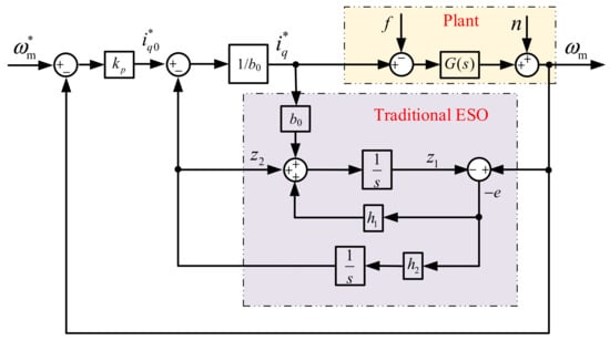
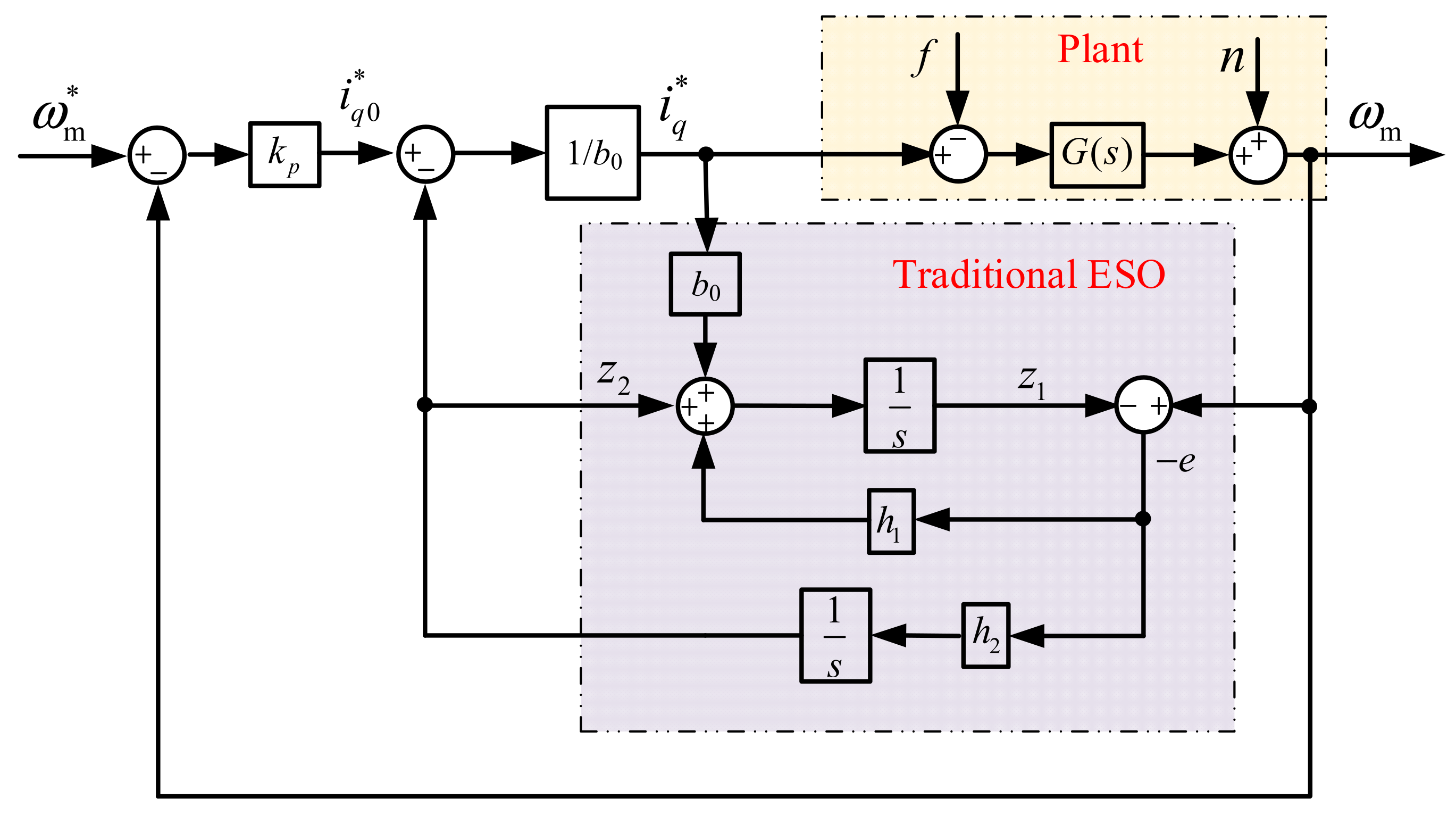
where e is the state observation error of ESO; z1 is the observation of state variable x1, i.e., the observation of rotational speed ω; z2 is the observation of state variable x2, i.e., the observation of perturbation f; b0 is the estimation of parameter b, which is usually taken to be b0 = b; and h1, h2 are the gain coefficients of ESO.
Convert Equation (7) into matrix form:
According to G = (sI-A)−1B, the transfer function of the ESO is obtained as follows:
Write the characteristic equation of ESO from (9):
According to Gao’s bandwidth method [19], make the system characteristic equation satisfy:
Obtain the gain coefficient of ESO as:
where ω0 is the observer bandwidth.
(3) SEF design: SEF compensates for the total disturbance estimate obtained from ESO in the system. This achieves the disturbance rejection performance of the system.
Input the error between the measured value and the given value into the system. Obtain initial current value through linear error feedback control rate:
where kp is the proportional gain of the controller, usually taken as
where ωc is the control loop bandwidth, a common rule is to choose ω0 = (3~5) ωc [19].
Then, the disturbance estimation value z2 obtained from ESO is compensated to the initial current command value iq0* to obtain the reference current command value
In summary, the traditional PMSM speed ADRC block diagram is shown in Figure 1.
Figure 1.
The traditional ADRC block diagram.
2.3. Performance Analysis of Traditional ADRC
Define the system disturbance rejection function Φf as: the transfer function between the total disturbance f and the system output speed ω; the system noise suppression function Φn as: the transfer function between the measurement noise n and the system output speed ω.
Organize (6) according to Figure 1 as
Write the transfer function of the traditional ESO according to (16)
According to (17) and Figure 1, the transfer function of ADRC system for disturbance and noise is obtained as:
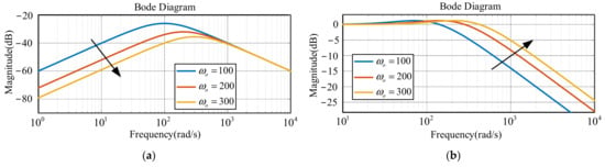
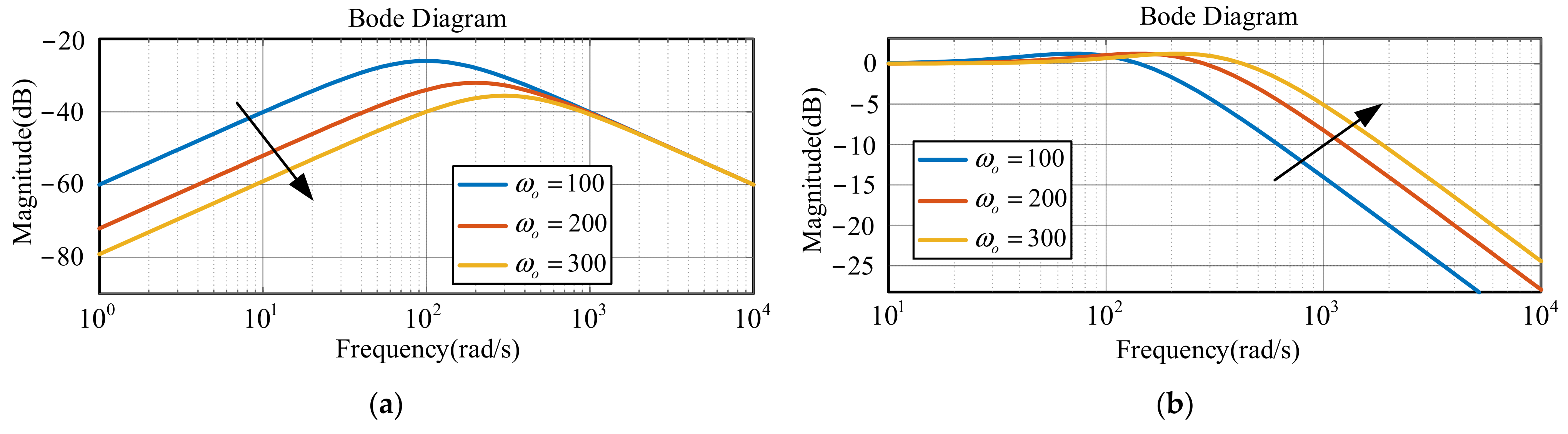
Bode plots are performed for Equations (18) and (19). Figure 2 shows the amplitude–frequency characteristic curves of Φf_ESO(s) and Φn_ESO(s) for the ADRC.
Figure 2.
Disturbance rejection performance and noise suppression performance amplitude–frequency curves characteristics of ADRC with different ω0. (a) Disturbance rejection performance. (b) Noise suppression performance.
When adjusting ADRC parameters, in order to achieve better dynamic performance, the bandwidth ω0 is usually increased. At this point, the disturbance rejection capability of the system is enhanced, but the noise suppression capability of the system is weakened. As the bandwidth increases, the change trend of the system’s disturbance rejection capability and noise suppression capability is opposite. This contradiction limits the choice of bandwidth and affects the dynamic performance of the system.
3. Modified ADRC for PMSM Speed Control
Compared with the cascaded double-layer ESO-based MADRC in reference [24], the proposed MESO in this paper abandons the series-connected dual-ESO framework. Instead, it constructs an integrated third-order observer by expanding disturbance derivative as extra state, which avoids multi-observer parameter coupling and realizes synchronous observation of the disturbance and its differential signal with a single bandwidth parameter, thus possessing different structure and disturbance observation principle.
3.1. Modified ADRC Design
Expanding the differential term of the perturbation into a new state variable x3 based on (5), the third-order state equation is established.
where y is the output of the system, i.e., the rotational speed ω; u is the control quantity, i.e., the given current; and b is the parameter of the state equation.
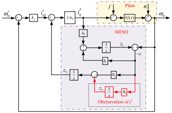
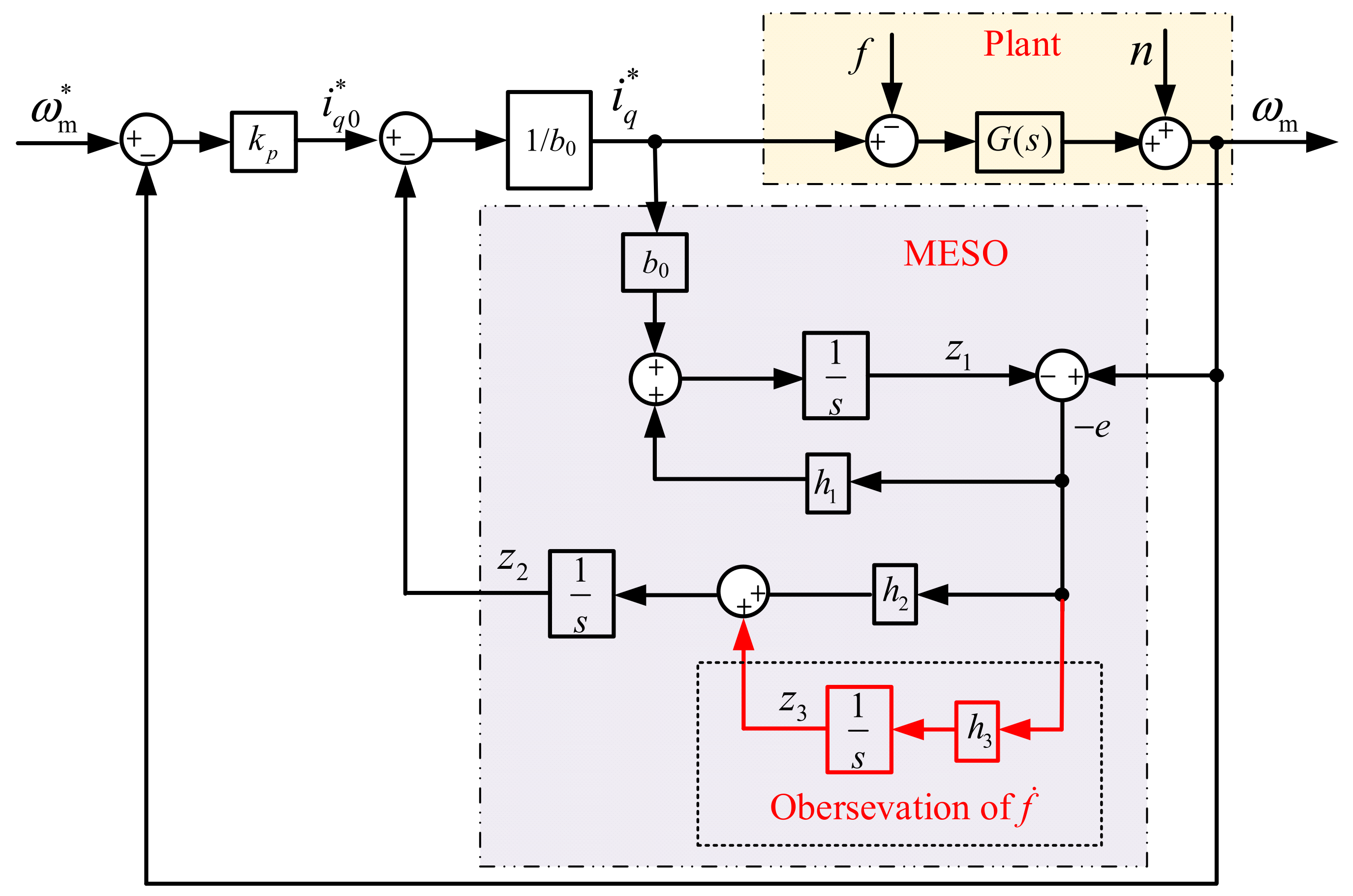
According to the above third-order state equation, the improved third-order expansion state observer (MESO) is constructed as follows
where e is the state observation error of MESO; z1 is the observation of state variable x1, i.e., the observation of rotational speed ω; z2 is the observation of state variable x2, i.e., the observation of perturbation f; z3 is the observed value of the state variable x3, i.e., the observed value of the perturbation differential term; b0 is the estimation of parameter b; and h1, h2, h3 are the gain coefficients of MESO.
Write the characteristic equation of MESO from (21)
According to Gao’s bandwidth method [19], the system characteristic equation is made to satisfy
The parameters of the modified extended state observer (MESO) are tuned using the pole-placement method proposed in Ref. [19]. All observer poles are placed at ω0 to minimize the observer gains for a given bandwidth, resulting in the following parameter relations:
When satisfying ω0 > 0, the roots of the characteristic equations are all on the left side of the complex plane, so the improved third-order dilated state observer has good stability.
The SEF is the same as the design in the traditional ADRC in the previous section, which satisfies
MESO can estimate the total perturbation more accurately by making multiple observations of the perturbation and the differential terms of the perturbation. Figure 3 shows the block diagram of the MADRC structure based on the MESO.
Figure 3.
Block diagram of MADRC structure based on the MESO.
3.2. Performance Analysis of MADRC
According to (19) and the block diagram of the structure of MESO in Figure 3, it can be obtained that
Write the transfer function of MESO from (26)
For the MESO-based MADRC structure proposed in this paper, the transfer function of the MADRC control system for disturbance and noise is obtained from the MESO transfer function (25) and Figure 3 as
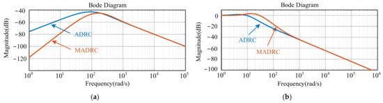
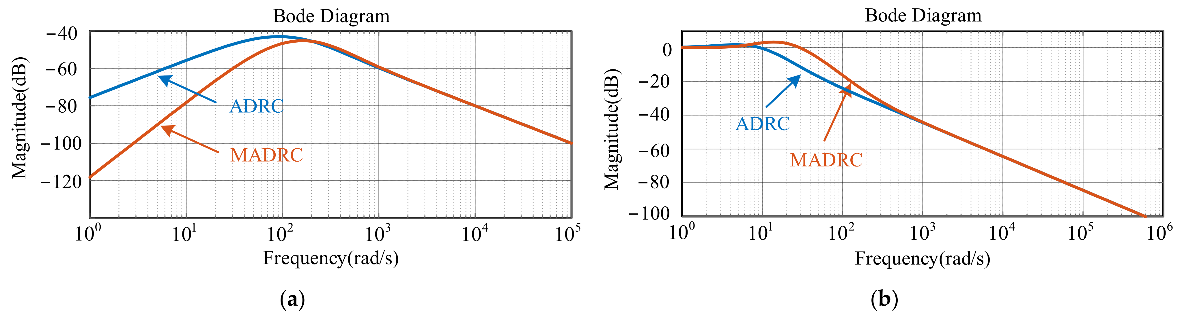
In order to reflect the advantages of MADRC, the same bandwidth ω0 = 200 is taken for ADRC and MADRC, and the baud plot is plotted.
Figure 4 shows the comparison of the amplitude–frequency characteristics of the disturbance rejection capability and noise suppression capability of the traditional ADRC and the MADRC proposed in this paper.
Figure 4.
Amplitude–frequency characteristics of MADRC and ADRC. (a) Disturbance rejection performance. (b) Noise suppression performance.
It can be seen that in the low-frequency band, the MADRC has a stronger disturbance rejection performance than the ADRC, and in the high-frequency band, the MADRC maintains the same noise suppression performance as the ADRC. However, the MADRC produces slight noise amplification in the frequency range of 10–200 rad/s. This is a natural trade-off of the third-order MESO, which enhances low-frequency disturbance rejection by raising observation gain. Since the main disturbances of PMSM speed regulation systems are low-frequency components, and MADRC keeps equivalent high-frequency noise suppression ability, this slight amplification will not affect the practical operation of the system.
3.3. Closed-Loop Stability Analysis of the Entire MADRC System
Combining the PMSM mechanical dynamics, the third-order MESO and linear state error feedback law, the observation error states
and speed deviation state ∆ω constructed to form a fourth-order augmented closed-loop state-space model:
The characteristic equation of the full closed-loop system is derived by solving det(sI-Acl) = 0:
The polynomial is decoupled into two independent stable subsystems: the speed feedback loop Pω(s) and the MESO subsystem Pe(s).
For Pω(s), the Routh array is:
The control gain satisfies kp = [(3~5)ω0]2 > 0, so the first column is fully positive. The single pole s = −kp is located in the open left half-plane, and the speed feedback loop is asymptotically stable.
For Pe(s), the Routh array is established as:
Given ω0 > 0, all elements in the first column are positive. No sign changes occur, which means all roots of Pe(s) lie in the open left half-plane, and the MESO error system is asymptotically stable.
All dynamic poles of the complete PMSM speed regulation system are s = −kp and triple repeated poles s = −ω0. For any positive observer bandwidth ω0 > 0, all poles are negative real numbers in the open left half-plane. According to the Routh–Hurwitz stability criterion, the proposed MADRC closed-loop speed control system is globally asymptotically stable under the bandwidth parameterization tuning rule.
4. Simulation Analysis
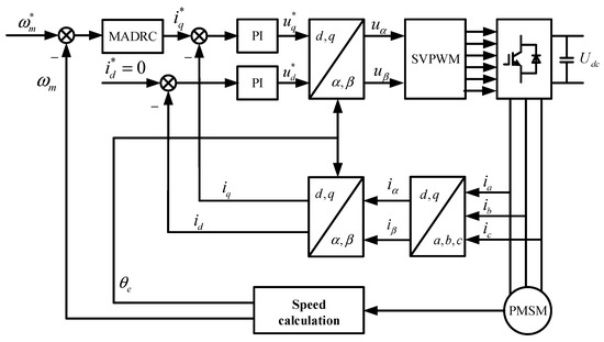
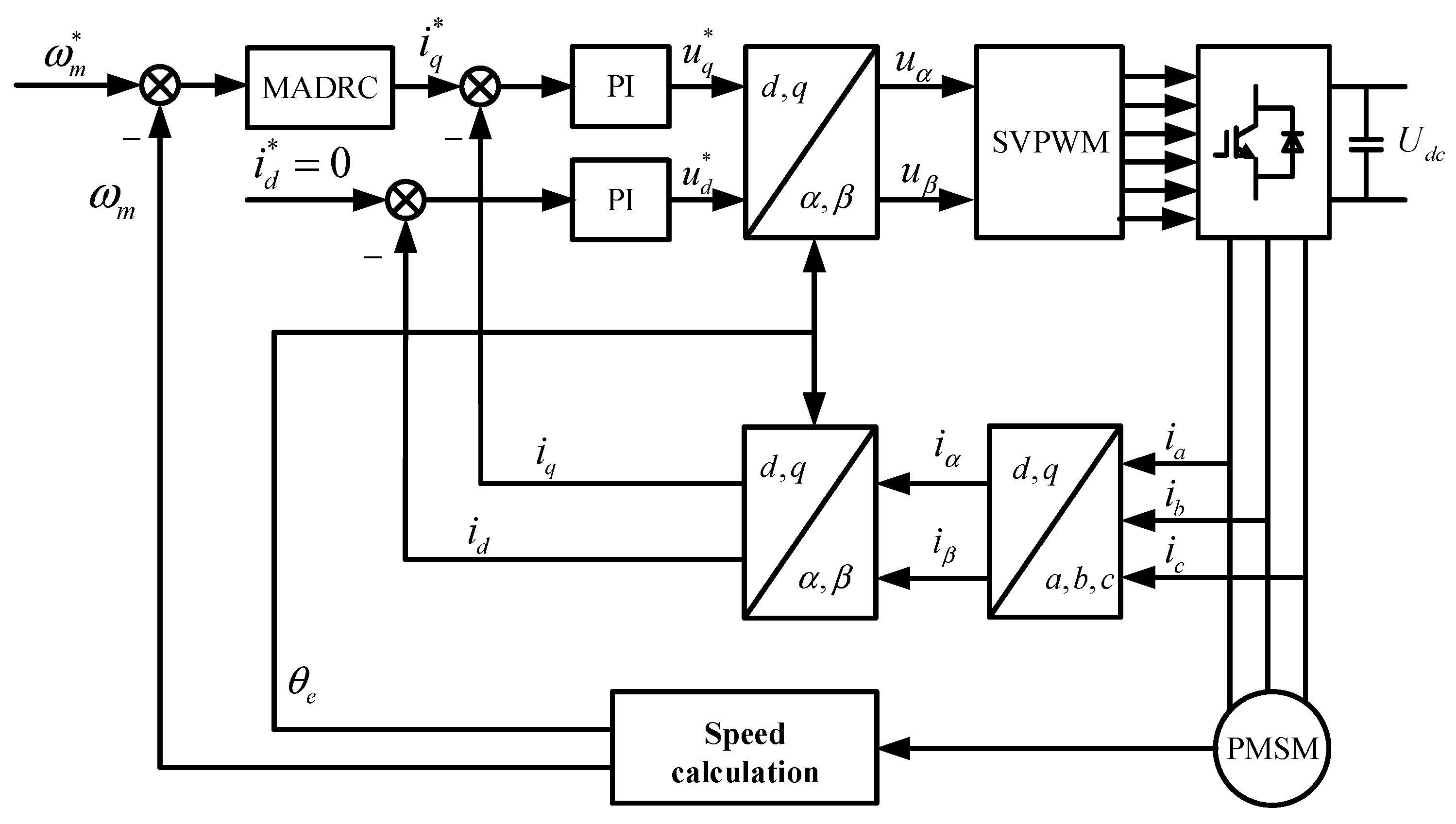
A PMSM control system model was built in the MATLAB/Simulink 2021b simulation environment to conduct comparative verification of the tracking performance, speed regulation performance, and anti-disturbance performance of the ADRC and MADRC controllers. In the simulation, the motor parameters and control parameters are shown in Table 1. The control block diagram is shown in Figure 5.
Table 1.
Simulation parameters.
Figure 5.
The control block diagram.
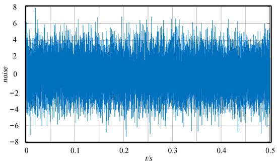
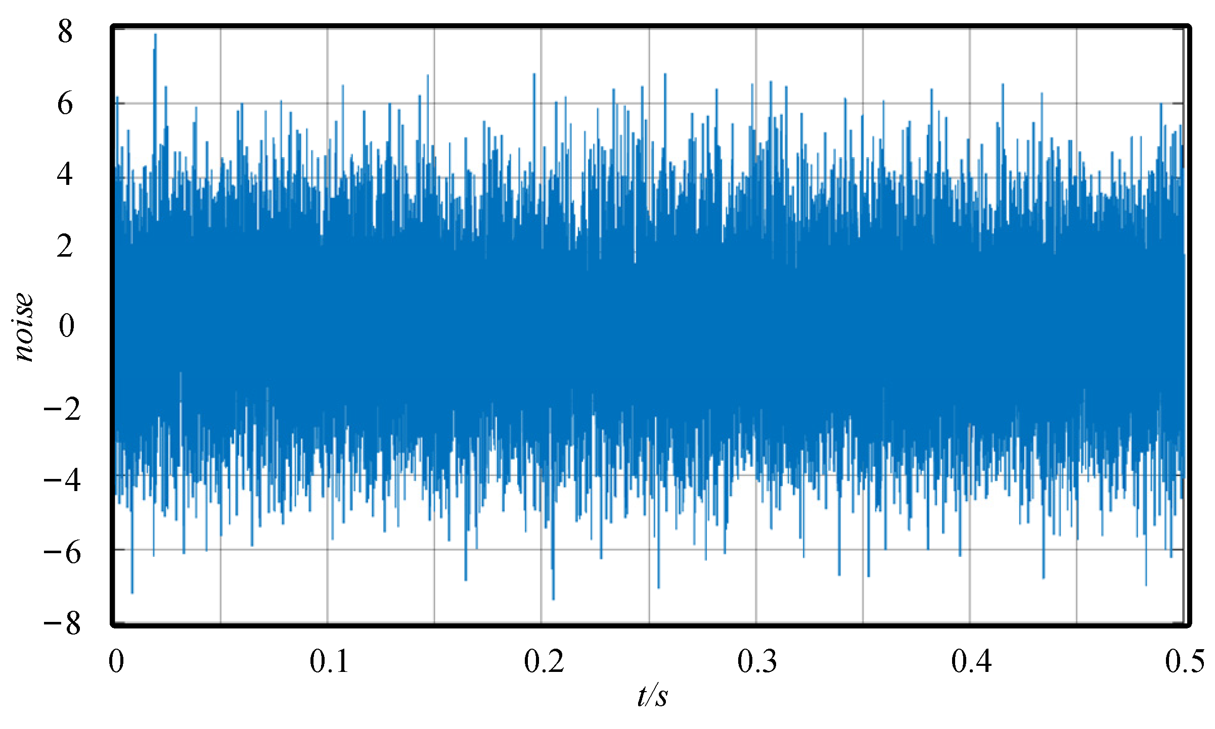
Measurement noise is superimposed on the speed feedback output channel. The noise power is set as 1 × 10⁻⁵, and the noise amplitude is restricted between [−5, 5] rpm/s. The actual noise waveform is shown in Figure 6. All contrast algorithms share the same noise excitation condition for fair performance evaluation of noise suppression capability.
Figure 6.
The noise waveform.
4.1. Tracking Performance Simulation
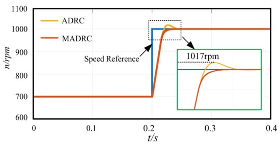
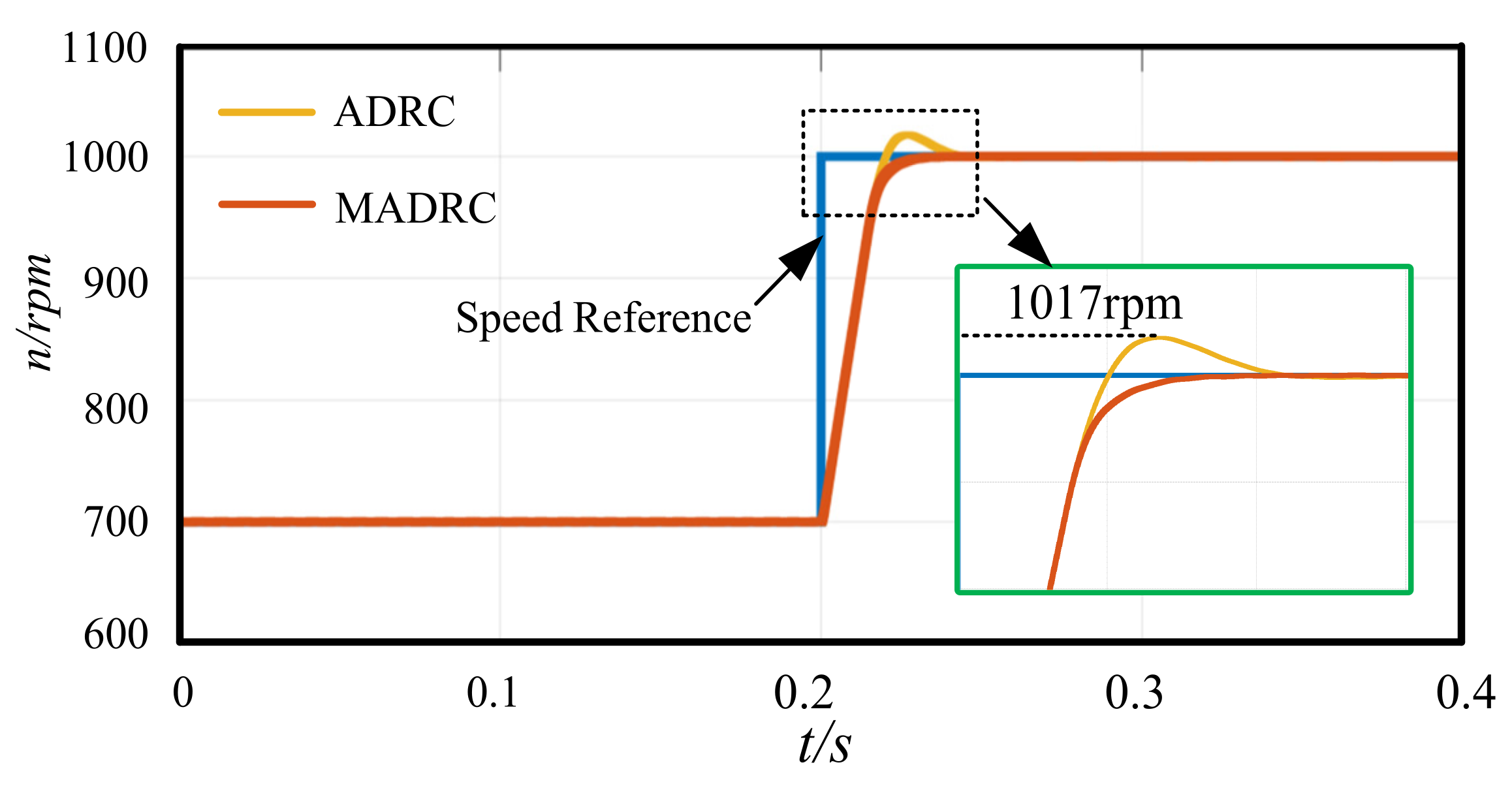
When the reference speed steps from 700 rpm to 1000 rpm, the speed response waveforms corresponding to the two control strategies are shown in Figure 7. In the simulation, the observer bandwidth ω0 is set to 200 rad/s. It can be seen that, the speed response curve of the ADRC speed controller exhibits an obvious overshoot phenomenon, while the MADRC speed controller is able to track the given command quickly without overshoot. Compared with ADRC, the settling time of the MADRC speed controller is significantly shortened, and its dynamic response is much faster. The above results indicate that MADRC has higher control accuracy and faster dynamic response speed.
Figure 7.
The speed response waveforms of ADRC and MADRC.
4.2. Anti-Disturbance and Anti-Noise Performance Simulations
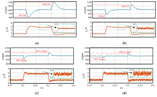
Apply load disturbances and test the system’s anti-disturbance performance. Inject noise into the speed measurement link and test the system’s anti-noise performance. Set the rotational speed to 1000 rpm and the step load value to 5 Nm in the simulation; apply the load suddenly at 0.2 s and remove the load suddenly at 0.3 s. By setting multiple groups of bandwidths ω0, we investigate the effects of bandwidth on the anti-disturbance and anti-noise performance of ADRC and MADRC. Figure 8 and Figure 9 show the simulated waveforms of rotational speed and current under load disturbance with ADRC and MADRC controllers, respectively. Performance indicators such as the rotational speed fluctuation value and current ripple magnitude are shown in Table 2 and Table 3, respectively.
Figure 8.
The speed and current waveforms with ADRC in simulations. (a) ω0 = 200, (b) ω0 = 400, (c) ω0 = 600, (d) ω0 = 800.
Figure 9.
The speed and current waveforms with MADRC in simulations. (a) ω0 = 100, (b) ω0 = 200, (c) ω0 = 300, (d) ω0 = 400.
Table 2.
The anti-disturbance performance of ADRC in simulations.
Table 3.
The anti-disturbance performance of MADRC in simulations.
It can be seen from the simulation results that with the increase in bandwidth, the speed fluctuation caused by load disturbance gradually decreases, and the adjustment time becomes shorter and shorter, which indicates that the anti-disturbance performance of the speed loop is enhanced. However, the speed fluctuation and current ripple increase significantly, which shows that the increase in bandwidth also improves the system’s sensitivity to noise, which is consistent with the theoretical analysis.
By comparing Figure 8a,b and Figure 9b–d, it can be found that at the same bandwidth values (ω0 = 200 and ω0 = 400), the anti-disturbance performance of the MADRC controller is superior to that of the ADRC controller, characterized by smaller speed fluctuation values and shorter adjustment time. However, the magnitudes of the q-axis current ripples are basically consistent, which indicates that the anti-noise performance of the two control methods is similar and is consistent with the results presented in the aforementioned Bode plots.
As can be seen from the theoretical analysis and simulation results presented above, the two controllers (ADRC and MADRC) exhibit similar anti-noise performance at the same bandwidth, while MADRC has significantly better anti-disturbance performance than ADRC. To balance the system’s anti-noise performance, the acceptable range of q-axis current ripple is set within 1 A, and the bandwidth ω0 is finally set to 400.
4.3. Robustness of the MADRC Controller in Simulations
All the above simulations are based on the premise that motor parameters can be accurately obtained, i.e., the parameter b0 is accurate. To verify the robustness of the MADRC controller against the parameter b0, simulations are conducted by setting b0 to twice and half of its nominal value b, respectively when ω0 = 400. Figure 10 shows the simulated waveforms of speed and current under load disturbance with the MADRC controller for different values of b0. Table 4 presents the specific performance indicators. By comparing Figure 10 with Figure 9d, it can be observed that when b0 deviates from its nominal value, both the speed fluctuation ∆ω and regulation time ∆t caused by load disturbance increase slightly, while the range of variation remains narrow. And it can be observed that when b0 deviates from its nominal value, the variation range of the speed fluctuation caused by load disturbance does not exceed ±5.1 rpm, and that of the regulation time is within ±1.2 ms. The simulation results demonstrate that the MADRC controller exhibits favorable robustness.
Figure 10.
The speed and current waveforms with MADRC in simulation. (a) b0 = 0.5b, (b) b0 = 2b.
Table 4.
The robustness performance of MADRC in Simulations.
5. Experimental Verification
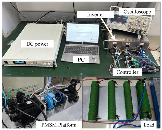
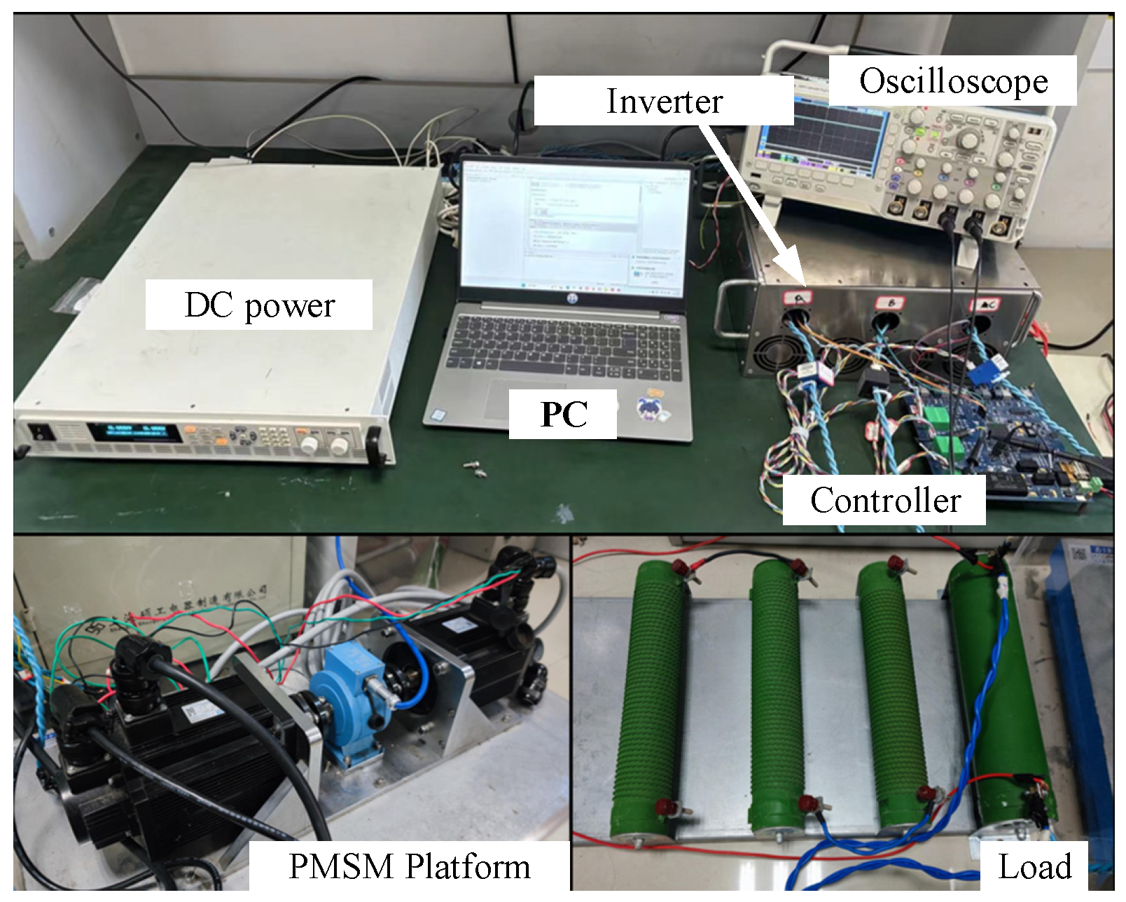
In order to verify the feasibility and effectiveness of the proposed strategy, experimental validation is carried out on the laboratory PMSM. Figure 11 shows the experimental platform, which is constructed with two PMSMs in back-to-back dragging structure. One machine is the prototype under test, while the counterpart operates as a generator. The generator’s terminal power is processed by an uncontrolled diode rectifier circuit. Sudden loading and unloading are implemented by quickly switching the external load resistance connected to the DC side of the rectifier. The inverter DC bus voltage is 200 V and the power device switching frequency is 20 kHz. The DSP-based controller executes control algorithm at 20 kHz sampling frequency. Rotational speed is measured via a 2500-line incremental encoder with four-fold frequency subdivision, and stator phase currents are sampled using Hall-effect current sensors.
Figure 11.
Experimental platform of PMSM drives.
5.1. Tracking Performance in Experiments
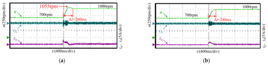
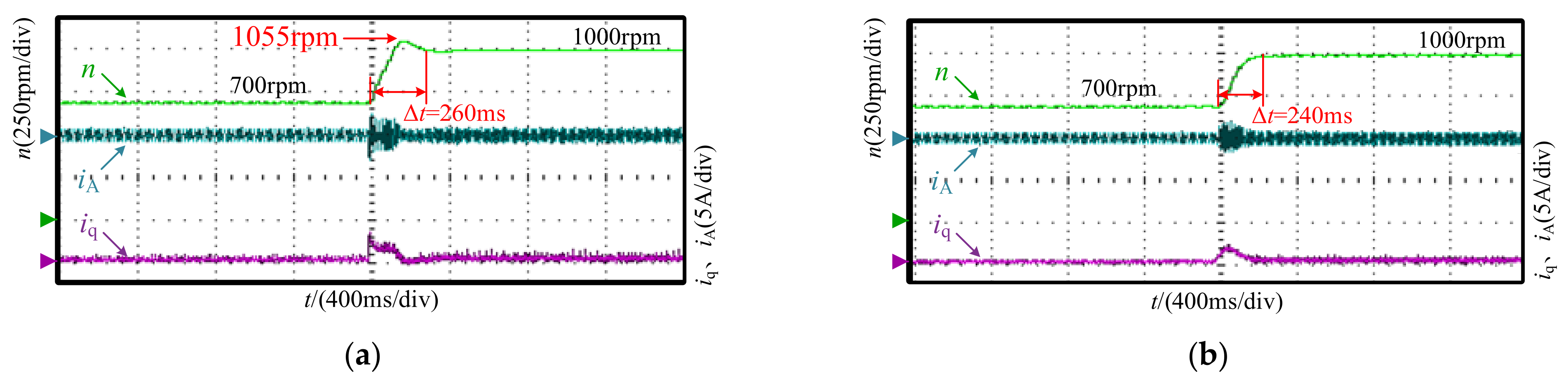
Under no-load conditions, the speed reference is stepped from 700 rpm to 1000 rpm to compare the speed tracking performance of the ADRC and MADRC strategies. The speed responses of the two control strategies are presented in Figure 12. Both strategies use the same bandwidth ω0, which is set to 400. It can be seen that during the speed reference step input, the speed response of the system with the ADRC speed controller exhibits a certain degree of overshoot, while the system with the MADRC speed controller shows no overshoot. In addition, under the same bandwidth condition, the command tracking speed of the MADRC speed controller is significantly faster.
Figure 12.
Step response of two control strategies at no load. (a) ADRC. (b) MADRC.
5.2. Anti-Disturbance and Anti-Noise Performance in Experiments
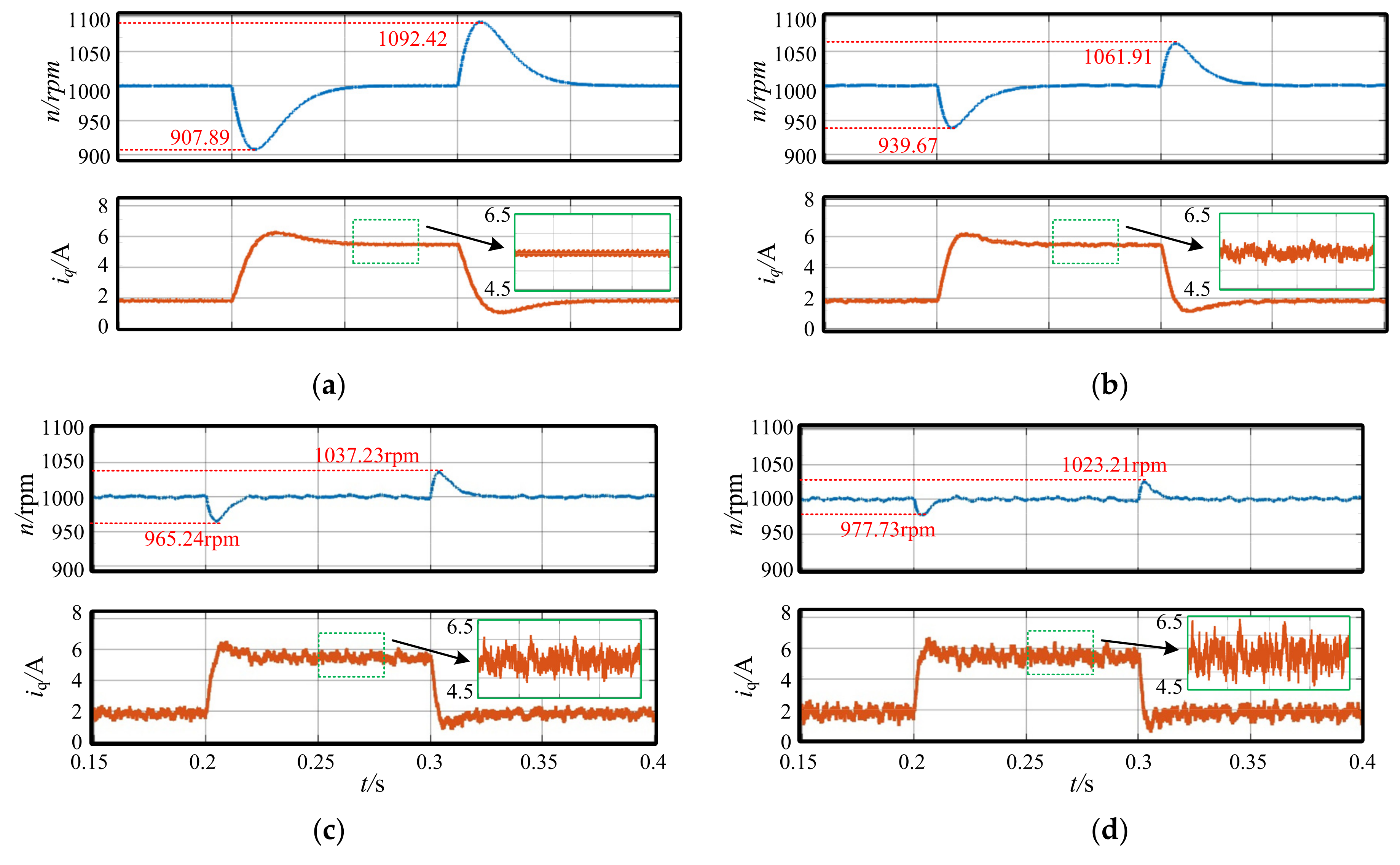
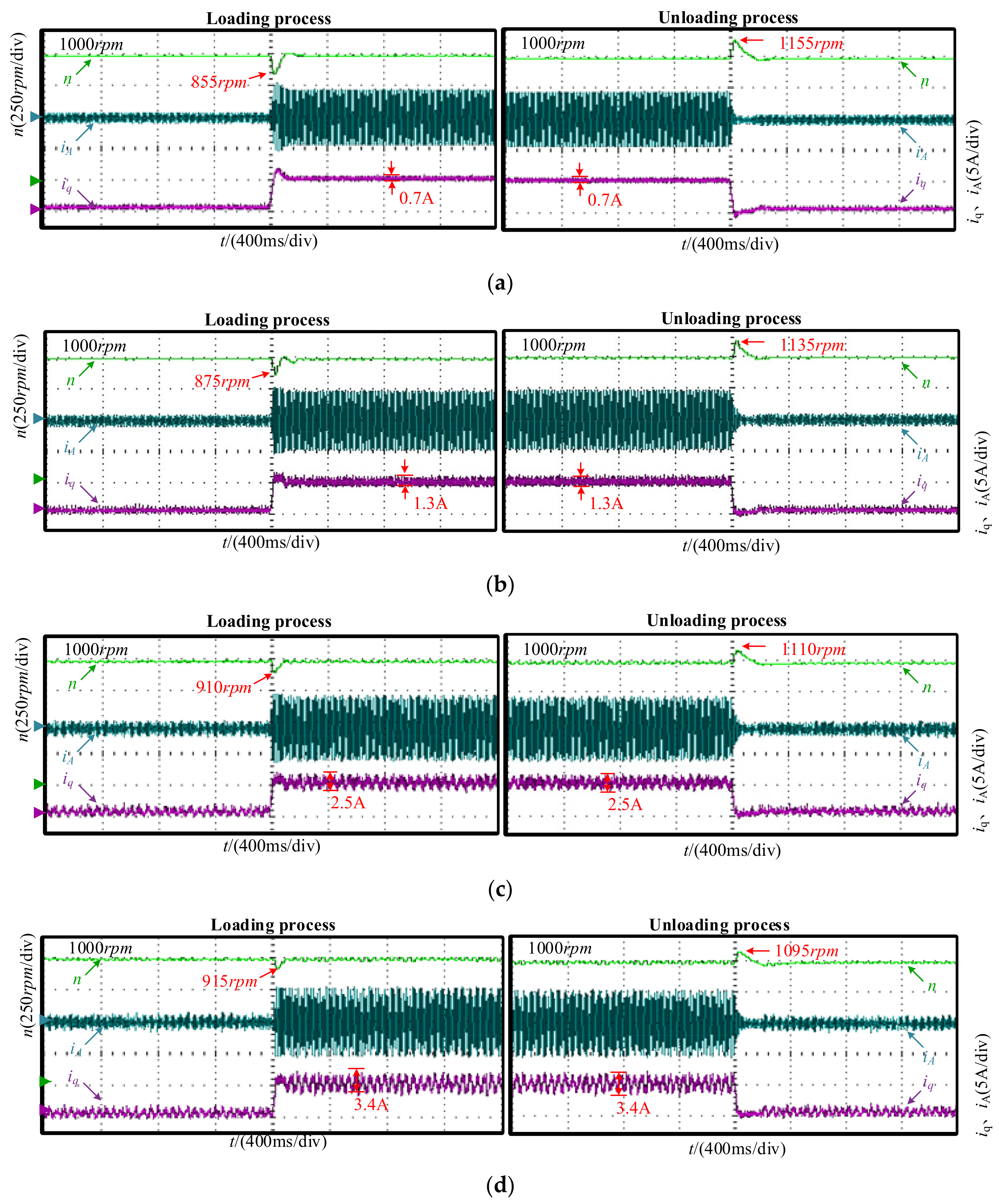
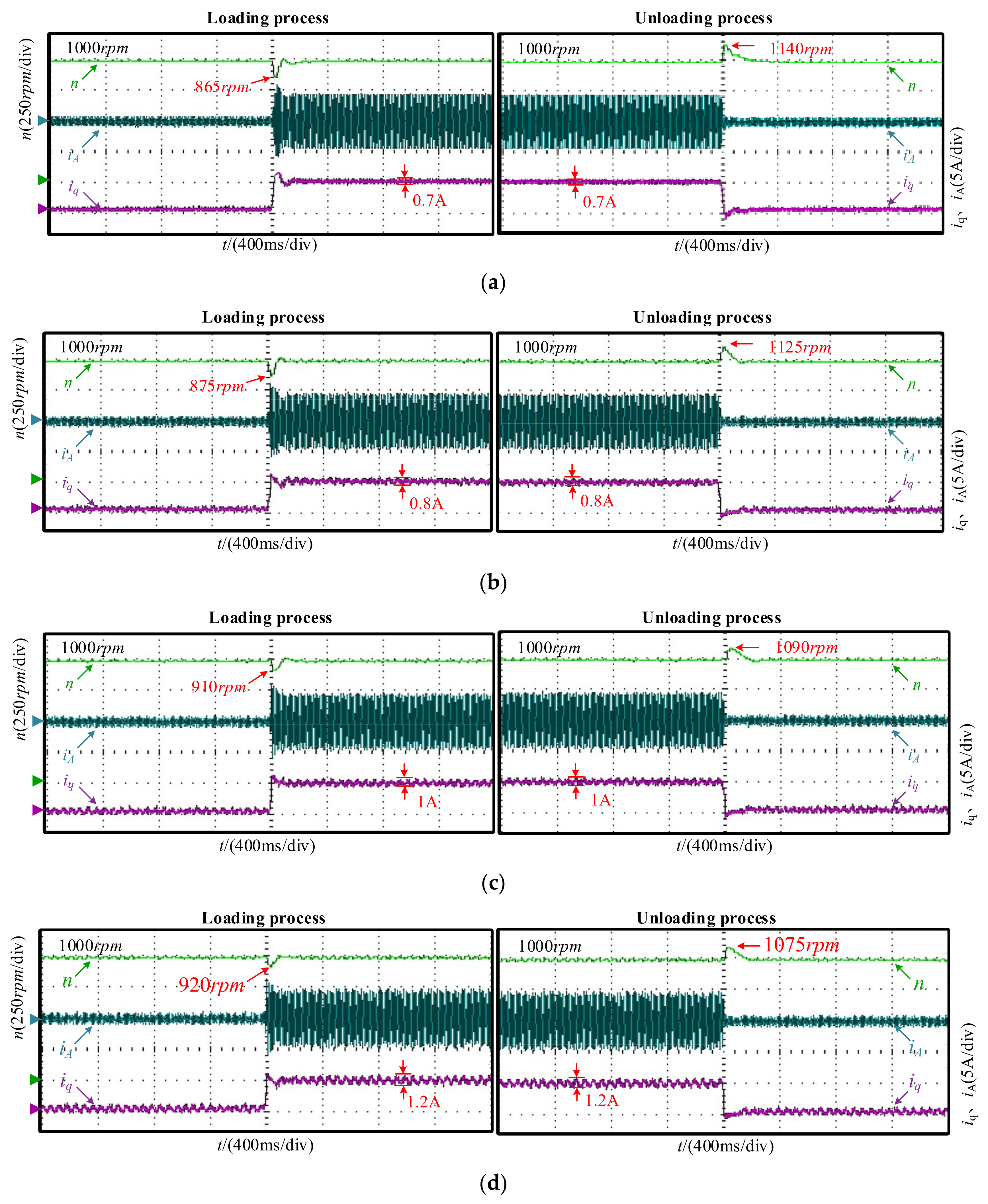
Apply load disturbances and test the system’s anti-disturbance performance. The prototype is first operated stably at 1000 rpm under no-load conditions, followed by a sudden application and removal of a 5 Nm load. Multiple groups of comparative tests are conducted for both ADRC and MADRC with different values of ω0 selected.
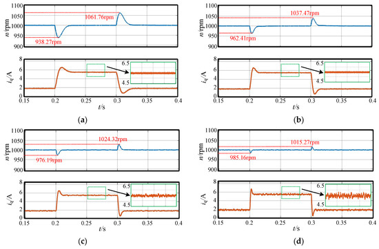
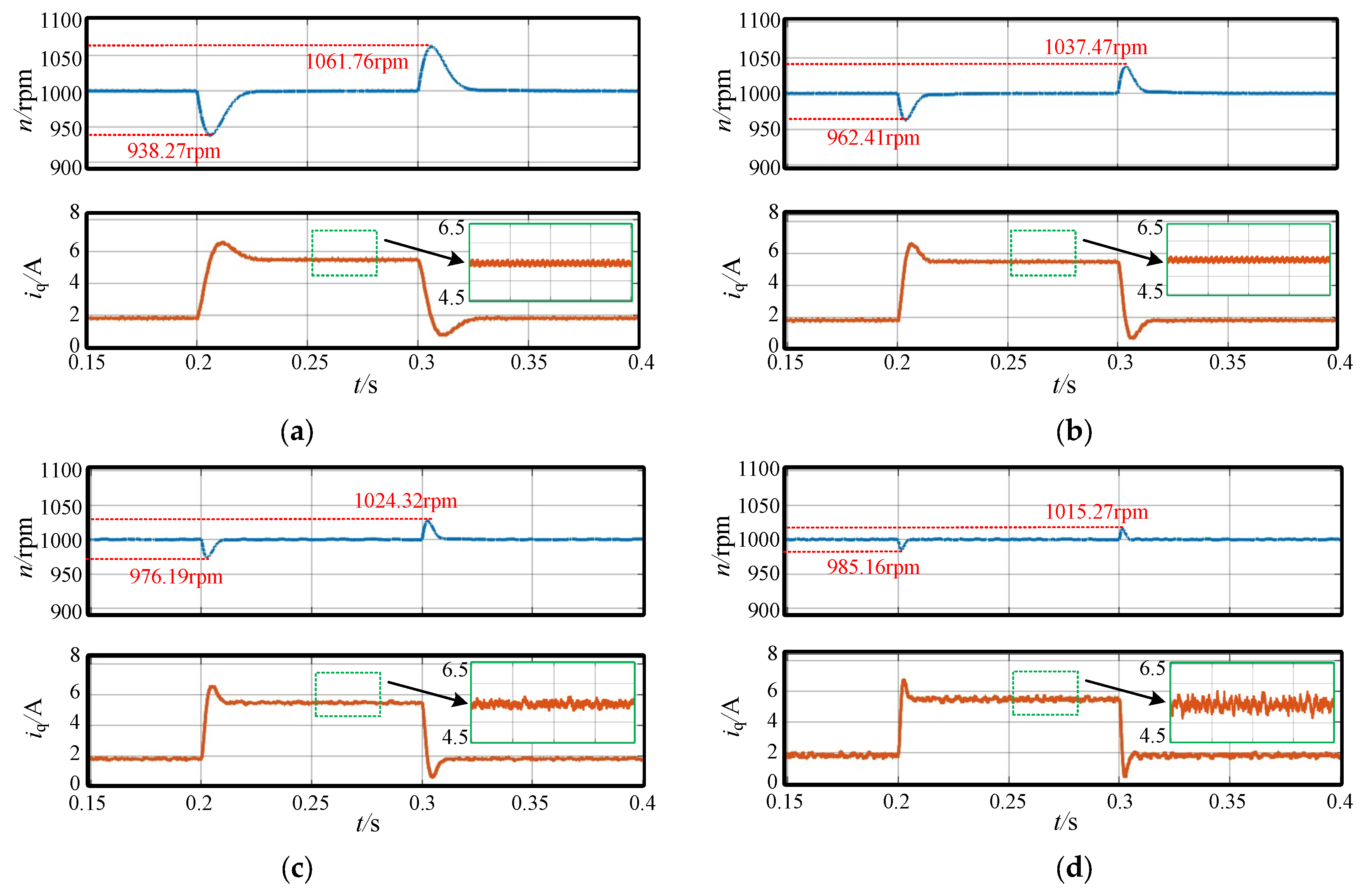
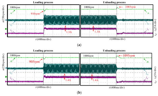
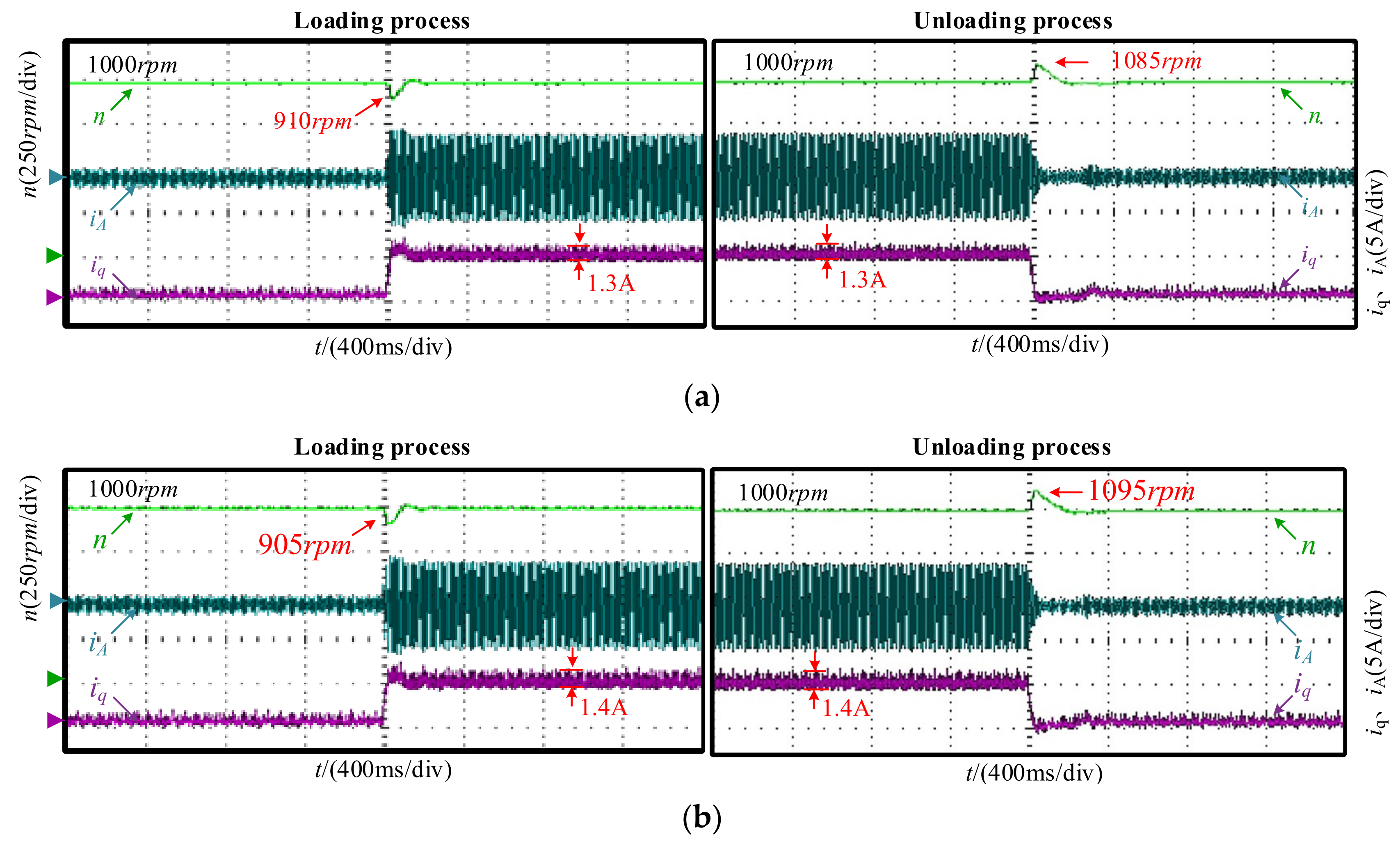
Figure 13 and Figure 14 show the experimental waveforms of rotational speed and current under load disturbance with ADRC and MADRC controllers, respectively. Performance indicators such as the rotational speed fluctuation value and current ripple magnitude are shown in Table 5 and Table 6, respectively.
Figure 13.
The speed and current waveforms with ADRC in experiments. (a) ω0 = 200, (b) ω0 = 400, (c) ω0 = 600, (d) ω0 = 800.
Figure 14.
The speed and current waveforms with MADRC in experiments. (a) ω0 = 100, (b) ω0 = 200, (c) ω0 = 300, (d) ω0 = 400.
Table 5.
The anti-disturbance performance of ADRC in experiments.
Table 6.
The anti-disturbance performance of MADRC in experiments.
It can be seen from Figure 13 and Table 5 that for the ADRC controller, as the bandwidth ω0 increases from 200 to 800, the speed drop decreases from 145 rpm to 85 rpm and the regulation time reduces from 190 ms to 125 ms during loading process; during unloading process, the speed overshoot decreases from 155 rpm to 95 rpm and the regulation time drops from 185 ms to 130 ms. The anti-disturbance performance of the system is enhanced, while the q-axis current ripple increases from 0.7 A to 3.4 A, which leads to a gradual degradation of the system’s anti-noise performance.
By comparing Figure 13a,b with Figure 14b,d, it can be observed that at the same bandwidth values (ω0 = 200, 400), the MADRC controller exhibits stronger anti-disturbance performance than the ADRC controller, with smaller speed drop and shorter regulation time. Nevertheless, the q-axis current ripples are comparable in magnitude, indicating that the anti-noise performance of the MADRC controller is equivalent to that of the ADRC controller. The above experimental results are consistent with the simulation results.
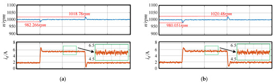
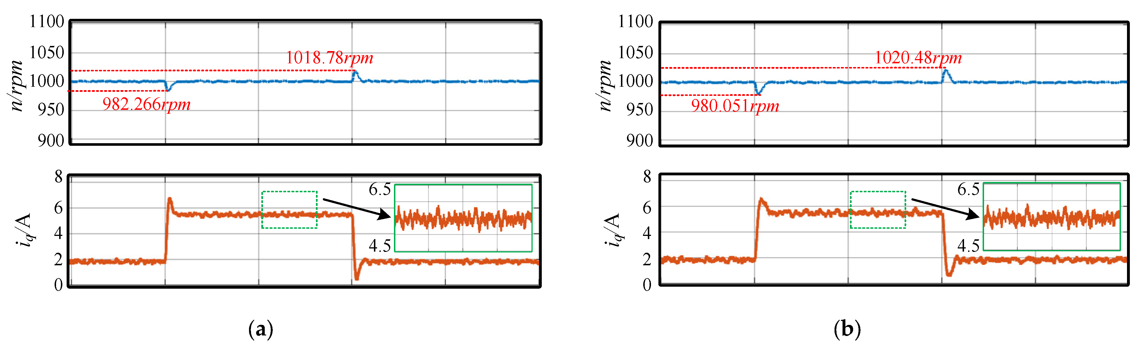
When the bandwidth of the ADRC controller is set to 800 and that of the MADRC controller is set to 400, their anti-disturbance performance is comparable, and a comparison of the anti-noise performance of the two systems is presented below. Figure 15 shows the experimental waveforms of the steady-state phase currents when the ADRC (ω0 = 800) and MADRC (ω0 = 400) controllers are adopted, respectively. It can be seen that the amplitude of the phase current fluctuates continuously when the ADRC controller is adopted, whereas the phase current amplitude remains highly stable with the MADRC controller. This is because the ADRC controller requires a larger bandwidth to achieve the same anti-disturbance performance as the MADRC controller, but a larger bandwidth will degrade the anti-noise performance of the system, thereby impairing the system stability.
Figure 15.
Comparison of phase current waveforms. (a) ADRC (ω0 = 800). (b) MADRC (ω0 = 400).
5.3. Robustness of the MADRC Controller in Experiments
To verify the anti-disturbance performance of the MADRC controller under different values of b0, load disturbance experiments are conducted with the estimated value of b0 set to twice and half of its nominal value b, respectively, at a fixed bandwidth of ω0 = 400. Figure 16 shows the experimental waveforms of speed and current under load disturbance with the MADRC controller for different values of b0. Table 7 presents the specific performance indicators.
Figure 16.
The speed and current waveforms with MADRC in experiments. (a) b0 = 0.5b. (b) b0 = 2b.
Table 7.
The robustness performance of MADRC in experiments.
By comparing Figure 14d and Figure 16, Table 6 and Table 7, it can be observed that when parameter b0 varies, the variation in the rotational speed does not exceed ±10 rpm, the variation in the regulation time is within ±5 ms, and the variation in the q-axis current is no more than ±0.1 A. The experimental results verify that the MADRC controller exhibits favorable robustness.
6. Conclusions
This paper proposes a MADRC control strategy for the PMSM speed regulation system based on an improved ESO. By observing disturbances and their differential terms multiple times, the accuracy of disturbance estimation has been improved, thereby enhancing the system’s capability to resist disturbances. This method solves the problem of weakened system anti-noise performance caused by increasing bandwidth in traditional ADRC. Simulations and experimental results show that:
- (1)
- For both the traditional ADRC and the proposed MADRC, a larger bandwidth leads to stronger anti-disturbance performance and higher dynamic performance of the system, but the anti-noise performance of the system will decrease accordingly.
- (2)
- At the same bandwidth, the proposed MADRC can achieve more excellent anti-disturbance performance compared with the traditional ADRC.
- (3)
- At the same bandwidth, the traditional ADRC and the proposed MADRC exhibit comparable anti-noise performance.
- (4)
- Compared with the traditional ADRC, the proposed MADRC can achieve the same anti-disturbance performance with a smaller bandwidth, thus better balancing the anti-noise performance of the system.
Practical design recommendations and inherent limitations of MADRC are concluded for engineering practitioners:
First, compared with conventional ADRC, the proposed MADRC improves anti-disturbance performance without sacrificing suppression performance. Hence, it can fully replace traditional ADRC for variable-load drive applications.
Second, an empirical rule ω0 = (3~5) ωc is recommended for parameter initialization in most engineering scenarios. Designers can determine b0 from the mathematical model of the controlled plant to assign initial ω0, and iterative alternating tuning of ω0 and b0 is required to achieve satisfactory anti-disturbance and anti-noise performance simultaneously.
Third, MADRC has no fundamental enhancement on noise suppression performance. Under ultra-high measurement noise condition, state estimation is inevitably corrupted, resulting in degraded dynamic response despite fine control parameter optimization.
Author Contributions
Conceptualization, W.L.; methodology, S.Z.; software, W.L.; validation, W.L. and S.Z.; investigation, W.L.; resources, H.M.; data curation, S.Z.; writing—original draft preparation, W.L.; writing—review and editing, S.Z. and X.F.; visualization, W.L.; supervision, X.F.; project administration, H.M. All authors have read and agreed to the published version of the manuscript.
Funding
This research received no external funding.
Data Availability Statement
The original contributions presented in this study are included in the article. Further inquiries can be directed to the corresponding author.
Conflicts of Interest
The authors declare no conflicts of interest.
References
- Chunjuan, Z.; Huizhen, W.; Weifeng, L.; Zirui, F.; Yongjie, W.; Yang, Z. Research of Rotor Positioning on Solving the Pole Pairs Mismatch between PMSM and Rotating Transformer. In Proceedings of the 2020 IEEE Applied Power Electronics Conference and Exposition (APEC), New Orleans, LA, USA, 15–19 March 2020. [Google Scholar]
- Hou, Q.; Ding, S.; Yu, X.; Mei, K. A Super-Twisting-Like Fractional Controller for SPMSM Drive System. IEEE Trans. Ind. Electron. 2022, 69, 9376–9384. [Google Scholar]
- Sun, Y.; Yang, M.; Wang, B.; Chen, Y.; Xu, D. Precise Position Control Based on Resonant Controller and Second-Order Sliding Mode Observer for PMSM-Driven Feed Servo System. IEEE Trans. Transp. Electrif. 2023, 9, 196–209. [Google Scholar] [CrossRef] [Scilit]
- Ding, S.; Zhang, B.; Mei, K.; Park, J.H. Adaptive Fuzzy SOSM Controller Design with Output Constraints. IEEE Trans. Fuzzy Syst. 2022, 30, 2300–2311. [Google Scholar]
- Ding, S.; Hou, Q.; Wang, H. Disturbance-Observer-Based Second-Order Sliding Mode Controller for Speed Control of PMSM Drives. IEEE Trans. Energy Convers. 2023, 38, 100–110. [Google Scholar] [CrossRef] [Scilit]
- Niu, Z.; Zuo, Y.; Wang, H.; Zhang, L.; Zhu, X.; Lee, C.H.T. Improved Low-Frequency Disturbance Rejection Property for Position Control of PMSM Using Generalized Extended State Observer. IEEE J. Emerg. Sel. Top. Power Electron. 2023, 11, 4739–4748. [Google Scholar] [CrossRef] [Scilit]
- Ma, L.; Mei, K.; Ding, S.; Pan, T. Design of Adaptive Fuzzy Fixed-Time HOSM Controller Subject to Asymmetric Output Constraints. IEEE Trans. Fuzzy Syst. 2023, 31, 2989–2999. [Google Scholar] [CrossRef] [Scilit]
- Qu, L.; Qiao, W.; Qu, L. An Extended-State-Observer-Based Sliding-Mode Speed Control for Permanent-Magnet Synchronous Motors. IEEE J. Emerg. Sel. Top. Power Electron. 2021, 9, 1605–1613. [Google Scholar] [CrossRef] [Scilit]
- Han, J.Q. From PID to active disturbance rejection control. IEEE Trans. Ind. Electron. 2009, 56, 900–906. [Google Scholar] [CrossRef] [Scilit]
- Grelewicz, P.; Nowak, P.; Czeczot, J.; Musial, J. Increment Count Method and Its PLC-Based Implementation for Autotuning of Reduced-Order ADRC With Smith Predictor. IEEE Trans. Ind. Electron. 2021, 68, 12554–12564. [Google Scholar] [CrossRef] [Scilit]
- Li, F.; Li, Z.; Zhang, X.; Guo, Y. Robust Model Predictive Current Control with Adaptive Extended-State-Observer for Permanent Magnet Synchronous Motor. In Proceedings of the 2023 IEEE International Conference on Predictive Control of Electrical Drives and Power Electronics (PRECEDE), Wuhan, China, 16–19 June 2023. [Google Scholar]
- Hu, H.; Du, J. Active Disturbance Rejection Control for Permanent Magnet Linear Synchronous Motor. In Proceedings of the 2021 13th International Symposium on Linear Drives for Industry Applications (LDIA), Wuhan, China, 1–3 July 2021. [Google Scholar]
- Hao, Z.; Yang, Y.; Gong, Y.; Hao, Z.; Zhang, C.; Song, H.; Zhang, J. Linear/Nonlinear Active Disturbance Rejection Switching Control for Permanent Magnet Synchronous Motors. IEEE Trans. Power Electron. 2021, 36, 9334–9347. [Google Scholar] [CrossRef] [Scilit]
- Qu, L.; Qiao, W.; Qu, L. An Enhanced Linear Active Disturbance Rejection Rotor Position Sensorless Control for Permanent Magnet Synchronous Motors. IEEE Trans. Power Electron. 2020, 35, 6175–6184. [Google Scholar] [CrossRef] [Scilit]
- Lin, P.; Wu, Z.; Fei, Z.; Sun, X.-M. A Generalized PID Interpretation for High-Order LADRC and Cascade LADRC for Servo Systems. IEEE Trans. Ind. Electron. 2022, 69, 5207–5214. [Google Scholar] [CrossRef] [Scilit]
- Liu, C.; Luo, G.; Xue, Z.; Zhou, Z.; Chen, Z. A PMSM speed servo system based on internal model control with extended state observer. In Proceedings of the IECON 2017—43rd Annual Conference of the IEEE Industrial Electronics Society, Beijing, China, 29 October–1 November 2017. [Google Scholar]
- Zhu, L.; Zhang, G.; Jing, R.; Bi, G.; Xiang, R.; Wang, G.; Xu, D. Nonlinear Active Disturbance Rejection Control Strategy for Permanent Magnet Synchronous Motor Drives. IEEE Trans. Energy Convers. 2022, 37, 2119–2129. [Google Scholar]
- Wang, Y.; Fang, S.; Hu, J.; Huang, D. Mult scenarios Parameter Optimization Method for Active Disturbance Rejection Control of PMSM Based on Deep Reinforcement Learning. IEEE Trans. Ind. Electron. 2023, 70, 10957–10968. [Google Scholar]
- Gao, Z. Scaling and bandwidth-parameterization based controller tuning. In Proceedings of the 2003 American Control Conference, Denver, CO, USA, 4–6 June 2003; IEEE: Piscataway, NJ, USA, 2003; pp. 4989–4996. [Google Scholar]
- Alonge, F.; Cirrincione, M.; D’Ippolito, F.; Pucci, M.; Sferlazza, A. Robust Active Disturbance Rejection Control of Induction Motor Systems Based on Additional Sliding-Mode Component. IEEE Trans. Ind. Electron. 2017, 64, 5608–5621. [Google Scholar] [CrossRef] [Scilit]
- Ye, S.; Yao, X. An Enhanced SMO-Based Permanent-Magnet Synchronous Machine Sensorless Drive Scheme with Current Measurement Error Compensation. IEEE J. Emerg. Sel. Top. Power Electron. 2021, 9, 4407–4419. [Google Scholar] [CrossRef] [Scilit]
- Zuo, Y.; Mei, J.; Jiang, C.; Yuan, X.; Xie, S.; Lee, C.H.T. Linear Active Disturbance Rejection Controllers for PMSM Speed Regulation System Considering the Speed Filter. IEEE Trans. Power Electron. 2021, 36, 14579–14592. [Google Scholar] [CrossRef] [Scilit]
- Sun, H.; Madonski, R.; Li, S.; Zhang, Y.; Xue, W. Composite Control Design for Systems with Uncertainties and Noise Using Combined Extended State Observer and Kalman Filter. IEEE Trans. Ind. Electron. 2022, 69, 4119–4128. [Google Scholar] [CrossRef] [Scilit]
- Cao, H.; Deng, Y.; Li, H.; Wang, J.; Liu, X. An Active Disturbance Rejection Control Based on Modified Extended State Observer for PMSM Speed Control Considering Measurement Noise. In Proceedings of the 2022 5th International Conference on Robotics, Control and Automation Engineering (RCAE), Changchun, China, 28–30 October 2022. [Google Scholar]



Disclaimer/Publisher’s Note: The statements, opinions and data contained in all publications are solely those of the individual author(s) and contributor(s) and not of MDPI and/or the editor(s). MDPI and/or the editor(s) disclaim responsibility for any injury to people or property resulting from any ideas, methods, instructions or products referred to in the content. |
© 2026 by the authors. Licensee MDPI, Basel, Switzerland. This article is an open access article distributed under the terms and conditions of the Creative Commons Attribution (CC BY) license.