


Abstract
To address head-end three-phase current unbalance and terminal power-quality deterioration caused by uneven three-phase load allocation in a low-voltage transformer area (LVTA), this paper proposes a DC-link-voltage-control-based phase-wise unbalanced power compensation strategy for a head-to-tail flexible interconnection structure embedded in the LVTA. The proposed structure consists of two three-phase four-leg converters sharing a common DC bus and connected to the head end and tail end of the LVTA, respectively. Different from conventional phase-wise compensation methods in which the DC side mainly acts as a power-transfer channel, the proposed strategy uses the DC-link voltage control of the head-end converter as the core of compensation power generation. Specifically, the outer DC-link voltage loop generates the total active compensation power, which is then allocated among the three phases according to the measured phase-power unbalance of the LVTA, thereby yielding the phase-wise compensation current references. Combined with phase-wise quasi-proportional-resonant current control, the compensation currents of different phase legs can be regulated without explicit positive-, negative-, and zero-sequence decomposition. Meanwhile, the tail-end converter adopts PQ control to support terminal power regulation and improve the terminal voltage quality of the LVTA. To provide a theoretical basis for the proposed method, a switching-cycle averaged model of the three-phase four-leg converter is established, and the leg-level phase-wise control characteristics are analyzed under the assumptions of a stiff DC link and symmetrical converter parameters. A control-oriented equivalent LVTA model is developed in MATLAB/Simulink. The proposed strategy is validated under steady-state unbalanced, RL load, load-disturbance, and equivalent feeder-impedance conditions. In addition, a conventional positive-, negative-, and zero-sequence compensation method is introduced as a benchmark for quantitative comparison. The simulation results demonstrate that the proposed method can effectively suppress the head-end three-phase current unbalance, maintain the DC-link voltage around its reference value, and improve the terminal voltage quality of the LVTA. Compared with the conventional sequence-component-based compensation method, the proposed strategy achieves effective unbalance mitigation while avoiding explicit sequence extraction and reducing the complexity of the compensation-current generation process. This study provides a feasible control framework for three-phase unbalance mitigation in flexible low-voltage transformer areas.
1. Introduction
With the increasing penetration of distributed generation, electric vehicles, and various power-electronic loads in low-voltage distribution networks, the operating conditions of low-voltage transformer areas (LVTAs) have become increasingly complex, and the three-phase unbalance problem has become more prominent. Existing studies have shown that three-phase unbalance may lead to increased neutral current, higher line losses, unbalanced loading of distribution transformers, and degraded node-voltage quality, and has become one of the key factors restricting the safe, economical, and high-quality operation of low-voltage distribution networks [1,2,3,4]. Therefore, research on efficient, continuous, and practically applicable methods for three-phase unbalance mitigation in LVTAs is of considerable theoretical significance and engineering value.
Existing methods for mitigating three-phase unbalance in LVTAs mainly include phase switching, phase reconfiguration, load transfer, and active compensation based on power-electronic interfaces. Conventional phase switching and load redistribution methods improve phase balance by changing the phase connection relationships of single-phase loads [5,6,7]. Although such methods can alleviate three-phase unbalance to some extent, they remain essentially load-side redistribution approaches. Their fast-response capability and fine regulation performance under continuously varying operating conditions are constrained by switching actions, load fluctuation characteristics, and implementation conditions, making them insufficient to meet the real-time and smooth mitigation requirements of LVTAs.
With the development of flexible distribution networks and flexible interconnection technologies, the use of power-electronic devices to establish controllable power-exchange channels has provided a new pathway for three-phase unbalance mitigation in LVTAs. Relevant studies have shown that flexible interconnection devices can not only regulate power exchange among feeders, but also possess the potential to participate in unbalanced-power mitigation [8,9,10,11,12]. On this basis, studies on low-voltage soft open points (SOPs) and flexible interconnection systems for transformer-area applications further indicate that flexible interconnection structures have gradually evolved from conceptual and principle analyses to control modeling and operational validation in LVTA scenarios [13,14,15]. Overall, existing studies have provided structural support and control foundations for the participation of flexible interconnection devices in three-phase unbalance mitigation in LVTAs. However, these studies mainly focus on operating characteristics and general control implementation, whereas the targeted mitigation of head-end three-phase current unbalance remains insufficiently addressed.
Research on unbalance compensation based on three-phase four-leg converters has evolved from phase-wise control to phase-wise compensation, and further to phase-wise power regulation for flexible transformer-area applications. Existing studies have verified the applicability of the three-phase four-leg topology under unbalanced operating conditions from the perspectives of unbalanced-load compensation, current regulation, and four-wire operation control [16,17,18,19,20], indicating that this topology provides a sound basis for independent phase regulation. On this basis, the study in [21] proposed a per-phase vector-control strategy, indicating that phase-wise control under unbalanced conditions can avoid complex symmetrical-component calculations. An independent sequence-control strategy based on positive-, negative-, and zero-sequence decoupling was proposed in [22], showing that effective regulation under unbalanced conditions can also be achieved through sequence extraction and multi-loop coordination, although the resulting control structure is relatively complex. Subsequently, [23] extended the phase-wise concept to the compensation level and proposed an independent phase-wise reactive-power compensation method, which reduced neutral current and network losses and improved line transfer capability through phase-independent compensation, thereby verifying the effectiveness of phase-wise compensation in unbalance mitigation. However, that study mainly focused on static reactive-power compensation devices in four-wire networks and did not address dynamic unbalance mitigation based on three-phase four-leg converters. Nor did it consider the coordination between the DC side and the AC side in head-to-tail flexible interconnection structures for LVTAs. Ning et al. [24] further extended the phase-wise compensation concept to flexible transformer-area applications and proposed an unbalance compensation strategy based on phase-wise power control, combined with phase-wise quasi-PR current control to mitigate head-end three-phase current unbalance. Nevertheless, in that strategy, the DC side still mainly served as a power-transmission channel, and no unified coordination mechanism was established between DC-link voltage control and AC-side phase-wise compensation power generation. Overall, existing studies have established a technical development path from phase-wise control to phase-wise compensation and then to phase-wise power regulation in flexible transformer areas. However, systematic studies are still lacking on how to use DC-link voltage as the control core to construct an intrinsic control chain that unifies compensation power generation and phase-wise regulation.
As shown in Table 1, existing methods have provided useful foundations for three-phase unbalance mitigation in LVTAs. However, most of them either rely on sequence decomposition or treat the DC side mainly as a power-transfer channel. In contrast, the proposed method uses the DC-link voltage loop as the core of total compensation power generation and allocates it among phases according to the measured phase-power unbalance.
Table 1.
Comparison of different three-phase unbalance mitigation methods.
A review of the existing literature indicates that three-phase unbalance mitigation in LVTAs has gradually evolved from conventional load-redistribution methods to active regulation methods based on flexible interconnection devices and three-phase four-leg converters. Nevertheless, two issues remain insufficiently addressed. First, most existing studies on flexible interconnection focus more on device configuration, feeder power exchange, operating characteristics, and general control implementation, whereas the targeted mitigation of head-end three-phase current unbalance has received limited attention. Second, existing converter-based unbalance compensation methods either rely on positive-, negative-, and zero-sequence extraction with multiple coordinated control loops, or treat the DC link mainly as an energy-transfer channel. The intrinsic relationship between DC-link voltage regulation and AC-side phase-wise compensation power generation has not been fully established.
To address these issues, this paper investigates a three-phase unbalance mitigation method for an internal head-to-tail flexible interconnection structure in a low-voltage transformer area (LVTA), using DC-link voltage as the control variable and phase-wise compensation as the implementation pathway. On this basis, an interconnected system consisting of two three-phase four-leg converters sharing a common DC bus is constructed, and a phase-wise unbalanced power compensation strategy based on DC-link voltage control is proposed. In the proposed method, the DC-link voltage of the head-end converter serves as the control core. The outer loop generates the total compensation power, which is then allocated among the three phases according to the three-phase power-unbalance condition of the LVTA. Subsequently, phase-wise quasi-proportional-resonant current control is used to track the compensation current references for each phase. The tail-end converter adopts PQ control to improve the terminal voltage quality of the LVTA. On this basis, a phase-decoupled averaged model of the three-phase four-leg converter is established, and a flexible LVTA simulation model is developed in MATLAB/Simulink R2024a to validate the proposed strategy.
The main contributions of this paper are as follows.
(1) A switching-cycle averaged model of the three-phase four-leg converter is established for the head-to-tail flexible interconnection structure of the LVTA. Under the assumptions of a stiff DC link and symmetrical converter parameters, the relationship between the leg duty-cycle variables and the corresponding phase currents is analyzed, which provides the theoretical basis for the design of the phase-wise quasi-PR current control without explicit sequence decomposition.
(2) A phase-wise unbalanced power compensation strategy based on DC-link voltage control is proposed. The strategy generates the total compensation power through the outer DC-link voltage loop, allocates it among the three phases according to the three-phase power-unbalance condition of the LVTA, and then realizes head-end three-phase unbalance mitigation through phase-wise current tracking control. In this way, the DC-link voltage regulation and AC-side phase-wise compensation power generation are incorporated into a unified control framework.
(3) A control-oriented LVTA simulation model is developed in MATLAB/Simulink to verify the proposed strategy. The effectiveness of the proposed method is evaluated under steady-state unbalanced, RL load, load-disturbance, and equivalent feeder-impedance conditions. In addition, a conventional positive-, negative-, and zero-sequence compensation method is introduced as a benchmark to further compare the unbalance mitigation performance and control implementation characteristics of the proposed method.
2. Structure of the Flexible Low-Voltage Transformer Area and Unbalance Compensation Strategy
2.1. Topology of the Flexible Low-Voltage Transformer Area
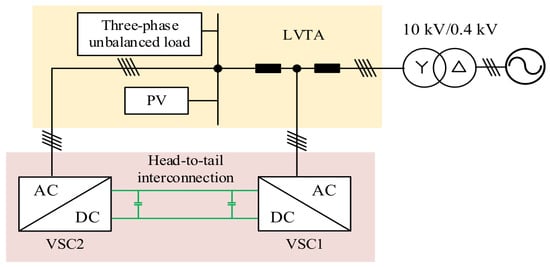
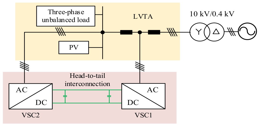
The typical topology of the flexible low-voltage transformer area is shown in Figure 1.
Figure 1.
Head-to-tail flexible interconnection topology embedded in the low-voltage transformer area.
The object of this study is a flexible low-voltage transformer area formed by embedding a head-to-tail interconnection system into a conventional low-voltage distribution transformer area. The head-to-tail interconnection system consists of two three-phase four-leg converters, denoted as VSC1 and VSC2, respectively. The DC sides of the two converters are connected through a common DC link, thereby establishing a bidirectional power-transmission channel between the head end and the tail end. Their AC sides are connected to the head end and the tail end of the LVTA, respectively. The three-phase output terminals are connected to the corresponding AC nodes, while the fourth leg is connected to the neutral line of the LVTA to enhance the system capability to accommodate unbalanced loads and zero-sequence currents.
Under this topology, the head-to-tail interconnection system provides an additional channel for energy transmission and power regulation between the head end and the tail end while maintaining the original power-supply structure of the LVTA unchanged. The head-end converter is mainly used for mitigating three-phase current unbalance at the head end of the LVTA, while the tail-end converter mainly undertakes terminal power regulation and power-quality improvement. Supported by the common DC link, bidirectional energy flow can be realized between the head and tail ends, thus providing the topological basis for the subsequent design of the phase-wise compensation strategy based on DC-link voltage control.
2.2. Unbalance Compensation Strategy for the Low-Voltage Transformer Area
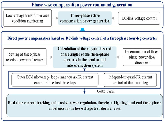
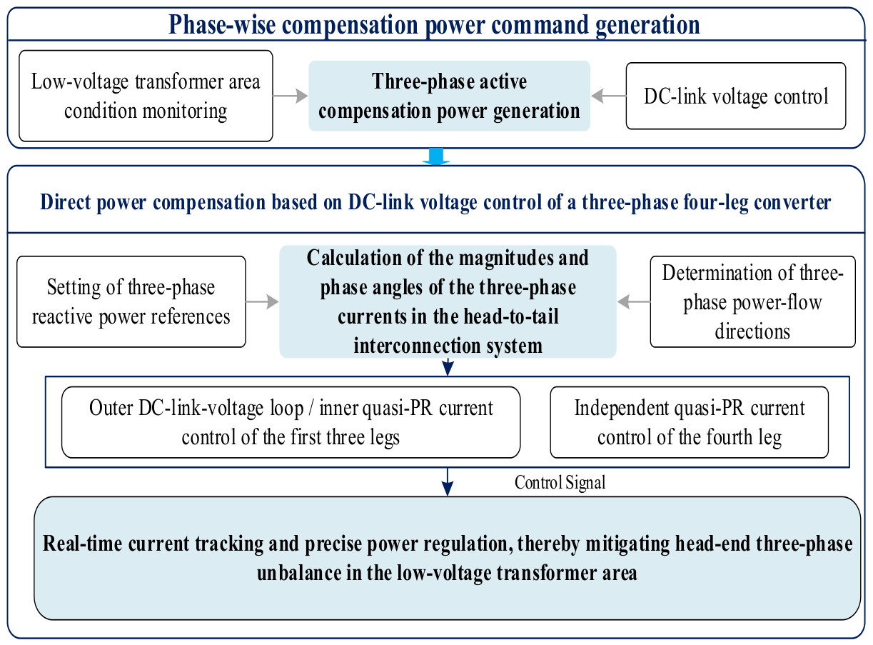
As shown in Figure 2, the proposed unbalance compensation strategy mainly consists of two stages: generation of phase-wise compensation power commands and tracking control of compensation current references.
Figure 2.
Control block diagram of unbalance compensation in the low-voltage transformer area.
In the phase-wise compensation power command generation stage, the operating state of the low-voltage transformer area is first detected, based on which the unbalanced power of each phase is calculated. On this basis, a control mechanism based on DC-link voltage is introduced, where the DC-link voltage of the head-to-tail interconnection system is used as the control variable to determine the total compensation power. The total compensation power is then allocated according to the degree of unbalance of each phase, thereby generating the phase-wise compensation power commands. This stage establishes the intrinsic relationship between DC-side energy regulation and AC-side phase-wise compensation demand and provides the power references for subsequent compensation current control.
In the compensation current control stage, the magnitudes and phase angles of the three-phase compensation currents are further determined according to the phase-wise compensation power commands and the transformer-area voltage information, thereby constructing the three-phase compensation current references. Meanwhile, combined with the constraint relationship between the three-phase compensation currents and the neutral-line current, the reference current of the fourth leg is obtained. Subsequently, phase-wise quasi-proportional-resonant current control is adopted to regulate the currents of the three-phase legs and the fourth leg in closed loop, thereby accurately tracking the output current references. Through the above control process, the head-end converter outputs the required compensation current to suppress unbalanced currents in the transformer area and reduce the three-phase unbalance index, while the tail-end converter adopts PQ control to improve the terminal power quality.
Overall, the proposed strategy takes DC-link voltage control as the core and incorporates compensation power determination, phase-wise power allocation, compensation current calculation, and current closed-loop regulation into a unified control framework. Without relying on complex sequence decomposition and multi-loop coupled control, it realizes head-end three-phase unbalance mitigation in the low-voltage transformer area while simultaneously improving terminal power quality.
3. Phase-Wise Quasi-Proportional-Resonant Control Theory
3.1. Analysis of the Phase-Wise Control Model
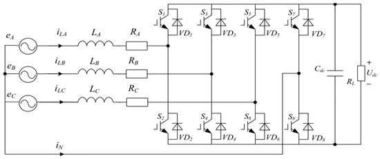
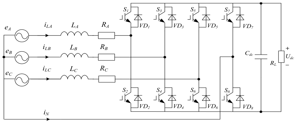
Figure 3 shows the topology of the three-phase four-leg converter.
Figure 3.
Topology of the three-phase four-leg converter.
Here, the variables represent the three-phase source voltage, the three-phase current, the neutral-line current, the three-phase loop resistance, the three-phase filter inductance, the DC-side support capacitor, and the DC-link voltage, respectively. The vector is defined as follows:
By applying the switching-cycle averaging method, the following expressions can be obtained:
The average duty-cycle relationship between the three-phase legs and the fourth leg can be written as
where is the average duty-cycle variable of the bridge leg.
By neglecting the inductor current vector, the following expression can be obtained:
Combining the above equations, the switching-cycle averaged model of the three-phase four-leg converter can be obtained as follows:
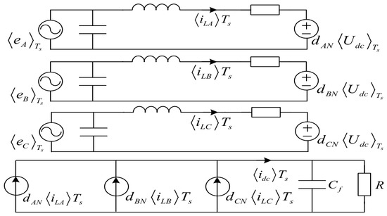
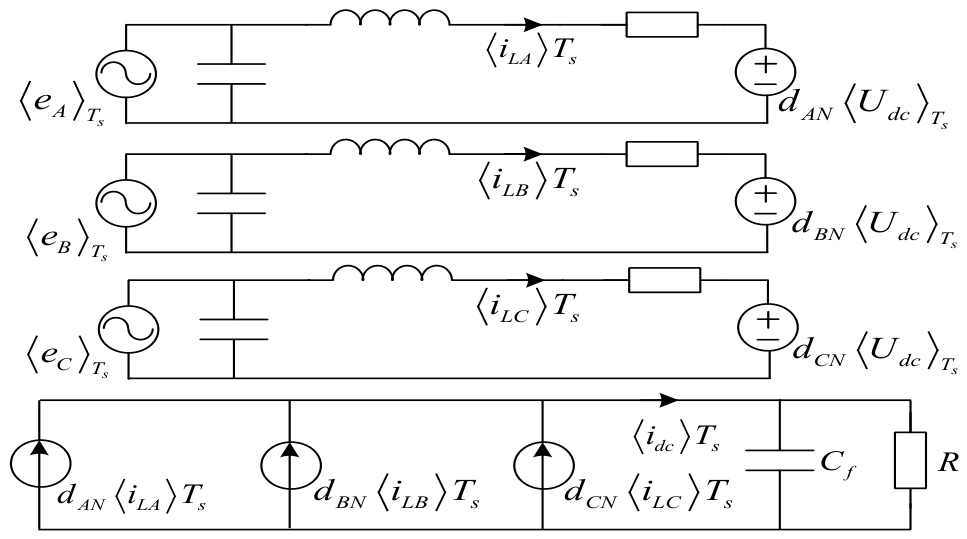
The switching-cycle averaged model of the three-phase four-leg converter can be represented by the equivalent circuit shown in Figure 4.
Figure 4.
Equivalent circuit of the switching-cycle averaged model.
It should be noted that the phase-wise control characteristic shown in Figure 4 is obtained under the assumptions of switching-cycle averaging, small DC-link voltage fluctuation, and approximately symmetrical converter parameters. Under these assumptions, the duty-cycle variable of each phase leg mainly affects the corresponding phase current, which provides a basis for phase-wise current regulation without explicit sequence decomposition. However, this does not imply complete decoupling at the system level, because the three phase legs are still indirectly coupled through the common DC-link voltage and the fourth-leg/neutral-current path.
The control of phase currents is based on quasi-proportional-resonant (quasi-PR) control, and the current-loop control equation of the three-phase four-leg converter can be expressed as
where denotes the reference current generated by the outer loop, and denotes the filter inductance of the four legs.
To effectively compensate for the voltage drop generated by the neutral-line inductor while improving DC-voltage utilization, the reference current of the fourth leg is calculated as follows:
The general transfer function of the quasi-PR controller is given by
where denotes the proportional gain of the controller, denotes the resonant coefficient, denotes the controller cutoff frequency, and denotes the resonant frequency of the controller, which is generally chosen as the grid frequency .
3.2. Controller Parameter Selection
To clarify the parameter settings used in the control system, the main PI and quasi-PR controller parameters are summarized in this section. The controller parameters were obtained through empirical tuning guided by time-scale separation between the outer DC-link voltage loop and the inner current loop. Specifically, the inner current-loop parameters were first adjusted to ensure fast current tracking without obvious oscillation, while the outer DC-link voltage loop was tuned with a relatively slower response to maintain DC-link voltage stability and reduce loop interaction. The final controller parameters used in the simulations are listed in Table 2.
Table 2.
Control parameters of the PI and quasi-PR controllers.
4. Control Strategy for the Flexible Low-Voltage Transformer Area
To address the requirements of head-end three-phase current unbalance mitigation and terminal power-quality improvement in the flexible low-voltage transformer area, an overall control strategy under the head-to-tail interconnection structure is established in this paper. In this strategy, the unbalanced power compensation of the head-end converter VSC1 serves as the core, while the power regulation of the tail-end converter VSC2 acts as auxiliary support. The two converters are connected through a common DC link to establish an energy-transmission relationship, thereby jointly realizing three-phase unbalance mitigation and terminal operating-quality improvement in the flexible low-voltage transformer area.
4.1. Phase-Wise Unbalanced Power Compensation Control of the Head-End Converter
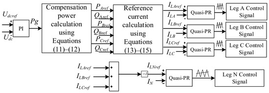
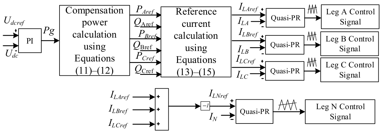
To effectively suppress the three-phase current unbalance at the head end of the LVTA, the head-end converter VSC1 adopts a phase-wise unbalanced power compensation strategy based on DC-link voltage control. The corresponding control block diagram is shown in Figure 5.
Figure 5.
Phase-wise power compensation control block diagram of VSC1 based on DC-link voltage control. The carrier-wave symbols denote the SPWM carrier/modulation stage.
The control structure of VSC1 consists of two parts: outer-loop compensation power generation and inner-loop current tracking. The outer loop takes the DC-link voltage as the control variable. According to the deviation between the DC-link voltage reference and the actual value, the total compensation power is generated through PI regulation, thereby coordinating DC-link voltage stabilization and unbalanced power regulation. Subsequently, based on the three-phase power-unbalance condition of the transformer area, the total compensation power is allocated among the three phases, thereby yielding the phase-wise active compensation power commands.
The average three-phase power of the transformer area is calculated by Equation (12), where the three-phase active power is measured at the head end of the transformer area, and the total compensation power is generated by the outer loop according to the DC-link voltage deviation.
Furthermore, the active compensation power reference of each phase is calculated as
In this formulation, is not an independently assigned power command, but the total active-power correction generated by the DC-link voltage loop. As shown in (12), is introduced into the calculation of , and then the phase-wise compensation power reference is obtained according to (13). Therefore, the DC-link voltage deviation is converted into the total compensation-power demand of the head-end converter and further allocated among the three phases according to the measured phase-power unbalance. In this way, the proposed strategy links DC-link voltage regulation with AC-side phase-wise compensation power generation, rather than treating the DC link only as a power-transfer channel.
After obtaining the phase-wise compensation power, the three-phase current references are further calculated according to the power references, as shown in Equation (14). To accurately represent the power-flow direction, a single-input comparator is introduced in the calculation of the three-phase current references. When the input power is positive, the comparator output is 1, indicating that power flows from the AC side of VSC1 to the DC side. When the input power is negative, the comparator output is −1, indicating that power flows from the DC side to the AC side of VSC1. In this manner, the current references retain consistent physical meaning under different power-flow directions.
The peak values and phase angles of the three-phase currents are calculated by Equations (15) and (16), respectively. Here, the three-phase reactive-power references are all set to zero, and the RMS values of the three-phase AC-side voltages are measured from the converter AC side.
To reduce the impact of voltage phase shift under three-phase unbalanced conditions on the accuracy of reference calculation, the phase angles of the three-phase voltages are measured by feeding the AC-side voltages into a phase-locked loop after a delay process. Once the current references are determined, the inner loop adopts phase-wise quasi-PR current control to regulate the currents of each phase in a closed loop and outputs modulation signals to the SPWM generation stage.
Compared with complex double-loop control methods based on positive-, negative-, and zero-sequence decomposition, the proposed control strategy directly constructs the current references using phase-wise compensation power as an intermediate variable, thus simplifying the control structure while maintaining effective compensation performance.
4.2. Power Control Strategy of the Tail-End Converter
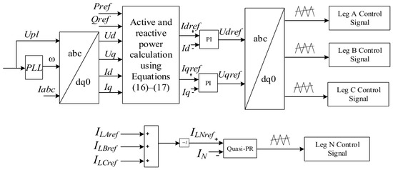
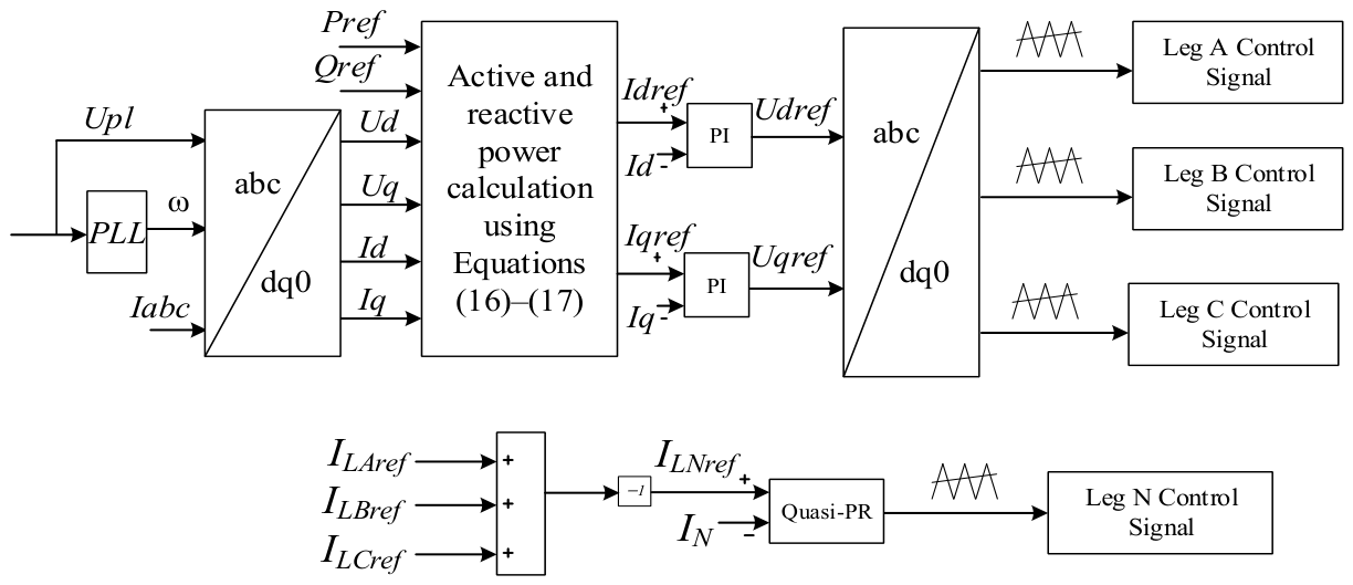
The tail-end converter VSC2 is connected to the tail end of the LVTA and is mainly used for terminal power regulation and voltage-quality improvement. In this paper, VSC2 adopts a conventional PQ control strategy, whose control block diagram is shown in Figure 6.
Figure 6.
Power control block diagram of VSC2. The carrier-wave symbols denote the SPWM carrier/modulation stage.
The active and reactive powers are calculated by Equations (17) and (18), respectively. The active-power reference is set to 5 kW, and the reactive-power reference is set to 2 kW. The fourth leg is still independently controlled according to Equation (10).
This part does not directly participate in the generation of head-end unbalanced compensation power but supports the overall control by establishing an energy-transmission relationship with VSC1 through the common DC link.
4.3. Overall Control Strategy and Framework
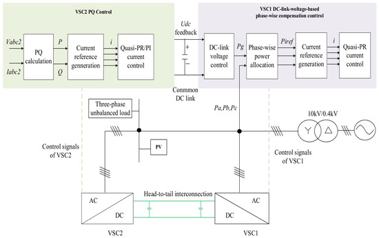
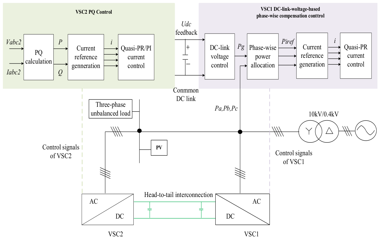
The overall control block diagram of the flexible LVTA is shown in Figure 7. VSC1 is responsible for head-end unbalanced power compensation, while VSC2 is responsible for tail-end power regulation. The two converters are connected through a common DC link, thereby forming the overall control system of the flexible LVTA.
Figure 7.
Overall control framework of the head-to-tail flexible interconnection system in the low-voltage transformer area.
From the perspective of the overall control strategy, VSC1 generates the total compensation power through the outer DC-link voltage loop, allocates it among the three phases according to the three-phase power-unbalance condition of the transformer area, and then outputs the compensation current through phase-wise quasi-PR current control, thereby mitigating head-end three-phase unbalance. VSC2 adopts PQ control to improve the terminal voltage quality of the transformer area. The common DC link provides a bidirectional energy-transmission channel between the head and tail ends, thereby constituting the overall control structure of the flexible low-voltage transformer area.
In general, the proposed strategy is based on head-end DC-link voltage control and combines phase-wise power allocation with current tracking control. Without relying on complex sequence decomposition and multi-loop coupled control, it realizes head-end three-phase unbalance mitigation while simultaneously improving terminal power quality.
5. Simulation Validation
To evaluate the effectiveness of the proposed control strategy, a control-oriented LVTA simulation model is established in MATLAB/Simulink. The simulation study focuses on the compensation-power allocation, current tracking performance, DC-link voltage stabilization, and robustness of the proposed method under different operating conditions. The steady-state compensation performance is first analyzed under the basic unbalanced operating condition. Then, the RL load condition and load-disturbance conditions are used to verify the adaptability and dynamic regulation capability of the proposed strategy. A feeder-impedance condition is also considered by inserting a series RL branch between the transformer secondary side and the head-end access point, so that the influence of feeder voltage drop and line loss on the compensation performance can be evaluated. The main simulation parameters are listed in Table 3.
Table 3.
Simulation parameters of the head-to-tail interconnection system.
To evaluate the three-phase unbalance degree of the transformer area, the three-phase current unbalance index is calculated according to [24] as follows:
where denotes the three-phase current unbalance index, denotes the RMS value of each phase current, and denotes the average RMS value of the three-phase currents.
5.1. Equivalent Modeling of the Three-Phase Unbalanced LVTA
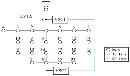
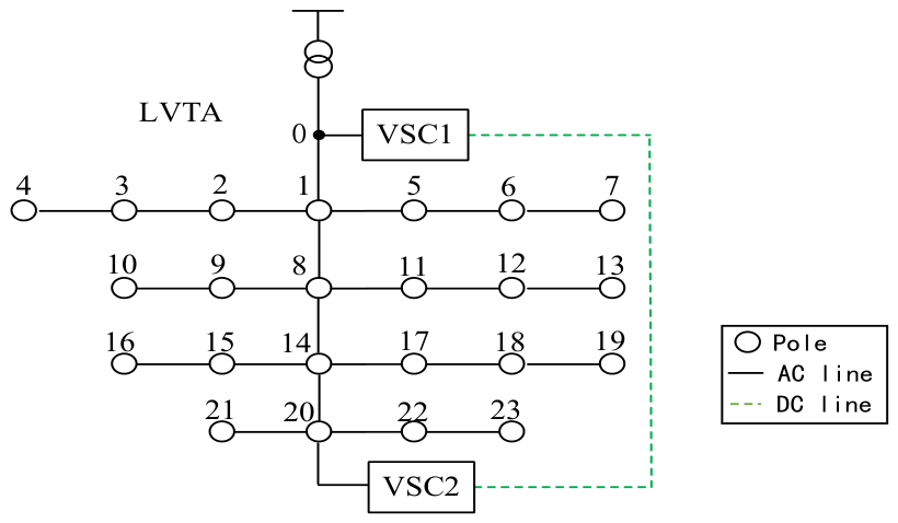
Figure 8 shows the head-to-tail interconnection model of the flexible LVTA.
Figure 8.
Control-oriented equivalent simulation model of the head-to-tail interconnected LVTA.
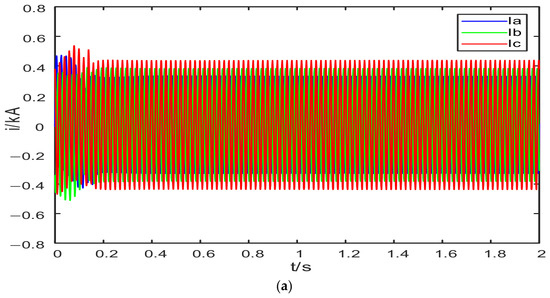
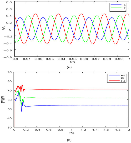
For the convenience of simulation analysis, Node 0 is defined as the head-end access point of the LVTA. The head-to-tail interconnection system is connected to the head end and the tail-end branch through VSC1 and VSC2, respectively. The equivalent load parameters are configured to reproduce the initial head-end three-phase power distribution of the LVTA. The power and current waveforms at the head end of the LVTA before embedding the head-to-tail VSC system are shown in Figure 9.
Figure 9.
Current and power waveforms at the head end of the low-voltage transformer area under the non-embedded condition. (a) Full-time-domain response of the three-phase current at the head end under the non-embedded condition. (a′) Enlarged steady-state view of the three-phase current at the head end under the non-embedded condition. (b) Three-phase power at the head end under the non-embedded condition.
Under the condition without the embedded head-to-tail interconnection system, the amplitude of the Phase-A current at Node 0 is the smallest, while that of the Phase-C current is the largest, as shown in Figure 9a. The simulation results indicate that the three-phase voltages at the head end remain essentially balanced; therefore, the difference in current amplitudes is mainly caused by unequal power distribution. As shown in Figure 9b, the three-phase powers at Node 0 are = 53.22 kW, = 63.24 kW, and = 72.24 kW, respectively. Among them, the Phase-A power is the smallest and the Phase-C power is the largest, indicating a pronounced imbalance in the three-phase power distribution at the head end. According to Equation (18), the three-phase current unbalance index at Node 0 is = 15.39%, indicating that without the embedded head-to-tail interconnection system, the LVTA exhibits a significant three-phase current unbalance problem.
5.2. Compensation Performance of the Proposed Strategy Under Steady-State Conditions
5.2.1. Analysis of the Power Redistribution Effect
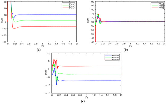
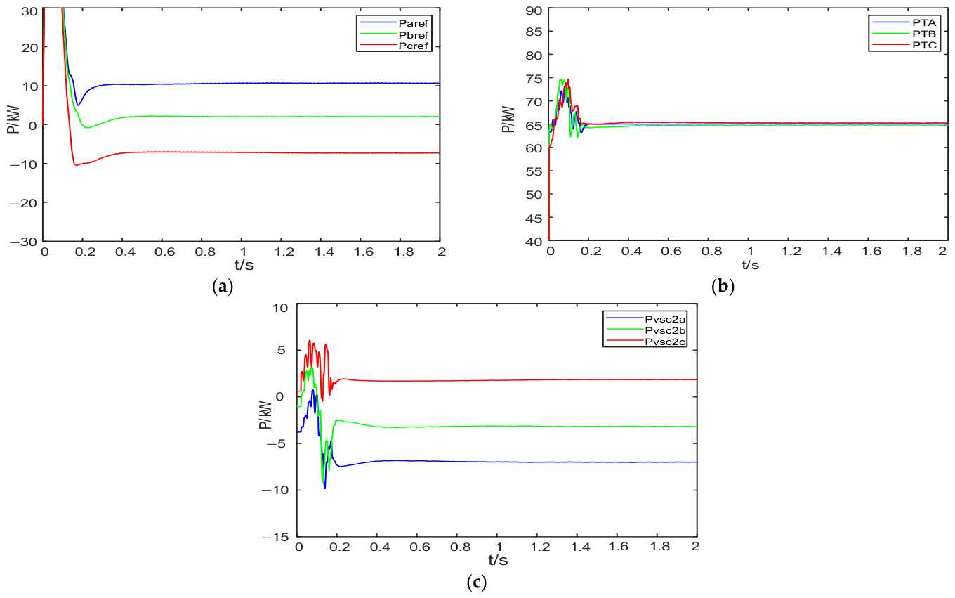
As shown in Figure 10a, under steady-state conditions, the three-phase compensation powers generated by VSC1 are = 10.66 kW, = 2.06 kW, and = −7.29 kW, respectively. This result indicates that the proposed strategy does not apply equal compensation to the three phases; instead, it performs differentiated allocation of the total compensation power according to the three-phase power-unbalance condition of the LVTA. Specifically, Phases A and B deliver power to the DC side, whereas Phase C receives power support from the DC side, indicating that the total compensation power generated by the outer DC-link voltage loop can be redistributed according to the compensation demand of each phase. On this basis, Figure 10b shows that the three-phase powers at Node 0 are adjusted from = 53.22 kW, = 63.24 kW, and = 72.24 kW before compensation to = 64.72 kW, = 65.45 kW, and = 64.81 kW after compensation, respectively, and become much more balanced. This indicates that the proposed method can effectively improve the unequal power distribution at the head end. Meanwhile, as shown in Figure 10c, the three-phase AC-side powers of VSC2 are = −6.95 kW, = −3.03 kW, and = 1.81 kW, respectively, indicating that the tail-end converter participates in the power-exchange process under steady-state conditions. This also shows that the head-to-tail interconnection system establishes an energy-transmission relationship between the head end and the tail end through the common DC link.
Figure 10.
Steady-state VSC1 compensation power, three-phase power at the head end of the low-voltage transformer area, and three-phase AC-side power of VSC2. (a) Three-phase compensation power of VSC1. (b) Three-phase power at the head end of the low-voltage transformer area. (c) Three-phase AC-side power of VSC2.
5.2.2. Analysis of the Steady-State Voltage and Current Compensation Performance
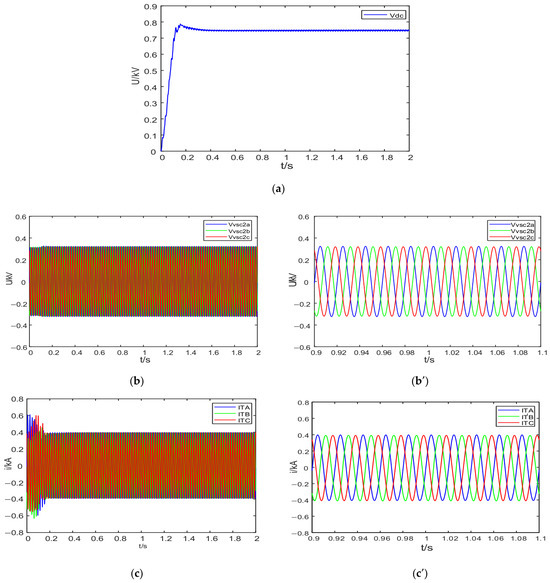
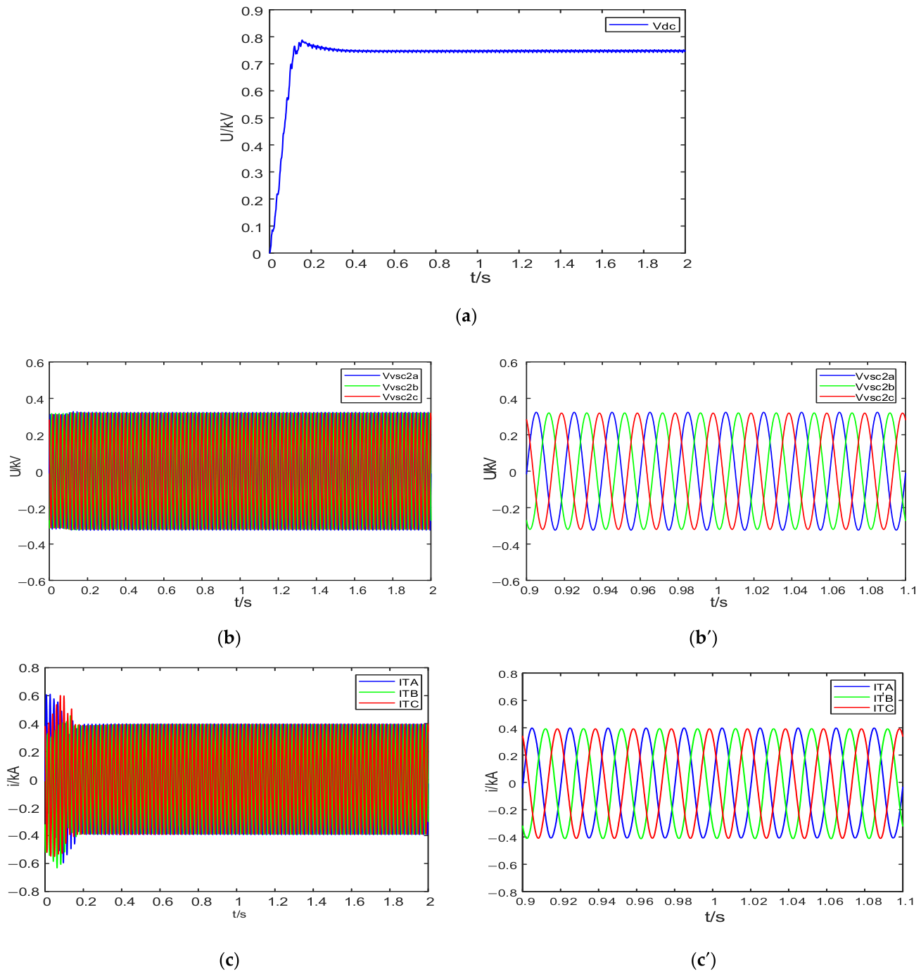
As shown in Figure 11a, under steady-state conditions, the DC-link voltage of VSC1 remains stable around 0.75 kV after the transient process, indicating that the proposed strategy can maintain the stability of the common DC link while performing unbalance compensation. As shown in Figure 11b, the three-phase AC-side voltages of VSC2 remain essentially balanced, indicating that the power regulation of the tail-end converter contributes to the improvement of terminal voltage quality. As shown in Figure 11c, the three-phase current at Node 0 becomes essentially balanced after compensation. According to Equation (18), the three-phase current unbalance index at Node 0 is significantly reduced from = 15.39% before compensation to = 0.69% after compensation, demonstrating that the proposed phase-wise unbalanced power compensation strategy based on DC-link voltage control can effectively suppress head-end three-phase current unbalance. These results indicate that, under steady-state conditions, the proposed method can simultaneously ensure DC-link stability, mitigate head-end three-phase unbalance, and improve terminal voltage quality.
Figure 11.
Steady-state DC-link voltage of VSC1, AC-side voltage of VSC2, and three-phase current at the head end of the low-voltage transformer area. (a) DC-link voltage. (b) AC-side voltage of VSC2. (b′) Enlarged steady-state view of the AC-side voltage of VSC2. (c) Three-phase current at the head end of the low-voltage transformer area. (c′) Enlarged steady-state view of the three-phase current at the head end of the low-voltage transformer area.
5.3. Comparative Analysis of Different Compensation Schemes
To further evaluate the role of the proposed phase-wise power allocation mechanism, different compensation schemes are compared under the same steady-state unbalanced operating condition. The uncompensated condition is used as the baseline. In addition to the equal-allocation scheme, a conventional positive-, negative-, and zero-sequence compensation scheme is introduced as a benchmark. In the equal-allocation scheme, the total compensation power is assigned equally to the three phases, namely = = = . In the conventional sequence-component-based scheme, the head-end three-phase currents are first decomposed into positive-, negative-, and zero-sequence components. The negative-sequence current component is used to generate the three-phase compensation current references, while the zero-sequence current is compensated through the fourth leg. Specifically, the zero-sequence current is calculated as , and the fourth-leg current reference is given by , where is the zero-sequence compensation coefficient. In this comparison, is set to 2.4. For a fair comparison, the converter topology, system parameters, load condition, power-to-current reference calculation, and phase-wise quasi-PR current controller are kept the same as those in the proposed method. Therefore, the comparison focuses on the influence of different compensation reference generation mechanisms on the head-end three-phase unbalance mitigation performance.
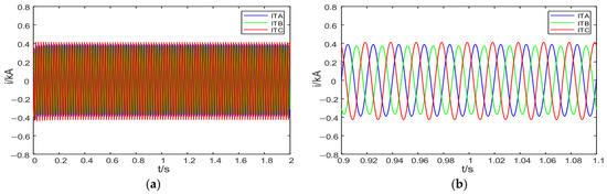
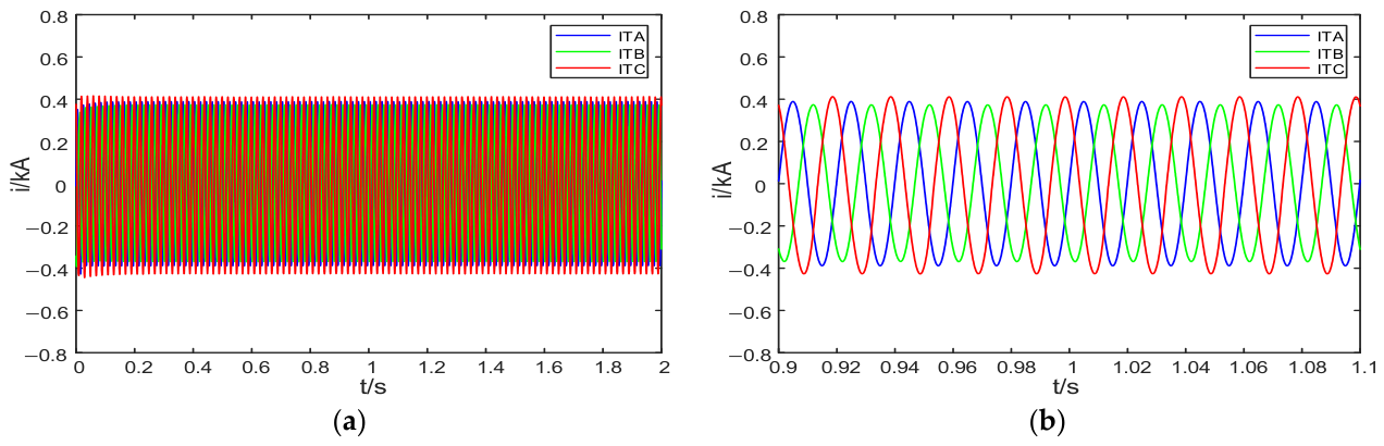
Figure 12 shows the head-end three-phase current waveforms under the conventional sequence-component-based compensation scheme. Compared with the uncompensated condition, the conventional sequence-component-based scheme can reduce the head-end current unbalance to a certain extent by suppressing the negative- and zero-sequence current components. The steady-state values in Table 4 are obtained by averaging the corresponding signals from 1.5 s to 2.0 s.
Figure 12.
Head-end three-phase current waveforms under the conventional sequence-component-based compensation scheme. (a) Full-time-domain response of the head-end three-phase currents. (b) Enlarged steady-state view of the head-end three-phase currents.
Table 4.
Quantitative comparison of different compensation schemes under steady-state unbalanced conditions.
The improvement percentage of each compensation scheme is calculated relative to the uncompensated condition as
where is the current unbalance index under the uncompensated condition, and is the current unbalance index after applying the corresponding compensation scheme.
As shown in Table 4, the uncompensated condition exhibits a clear three-phase current unbalance at the head-end measurement point, with a current unbalance index of 15.39%. The equal-allocation scheme reduces the current unbalance index to 7.65%, corresponding to a reduction percentage of 50.29%. However, because the total compensation power is equally assigned to the three phases, the different compensation demands of phases A, B, and C cannot be accurately matched. Therefore, the three-phase powers at the head-end measurement point remain different, and the current unbalance index is still higher than that obtained using the proposed method.
The conventional positive-, negative-, and zero-sequence compensation scheme reduces the current unbalance index to 7.06%, corresponding to a reduction percentage of 54.13%. Nevertheless, this value is still higher than that obtained using the proposed method. This is because the conventional sequence-component-based scheme mainly compensates the extracted unbalanced current components, whereas the proposed method directly allocates the total compensation power according to the measured phase-power deviation. As a result, the proposed method provides a more targeted phase-wise power compensation effect, reduces the current unbalance index to 0.69%, and achieves the highest reduction percentage of 95.52%. In addition, compared with the conventional sequence-component-based scheme, the proposed method does not require explicit positive-, negative-, and zero-sequence extraction. Instead, the phase-wise compensation power references are directly generated from the measured phase powers and the DC-link voltage-loop output. Therefore, the compensation current reference generation process is simplified while maintaining better unbalance mitigation performance. This comparison demonstrates that the performance improvement of the proposed method is mainly attributed to the phase-wise compensation-power allocation mechanism rather than merely to the insertion of the head-to-tail VSC system.
5.4. Dynamic Response Characteristics Under Load-Disturbance Conditions
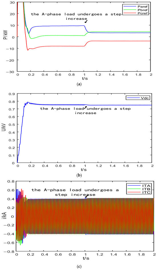
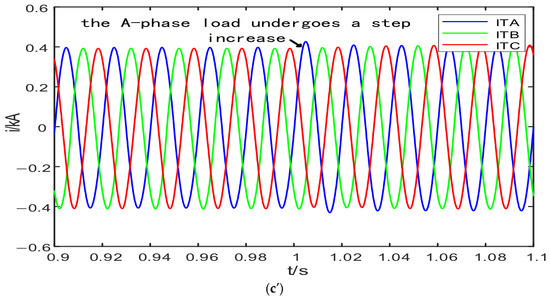
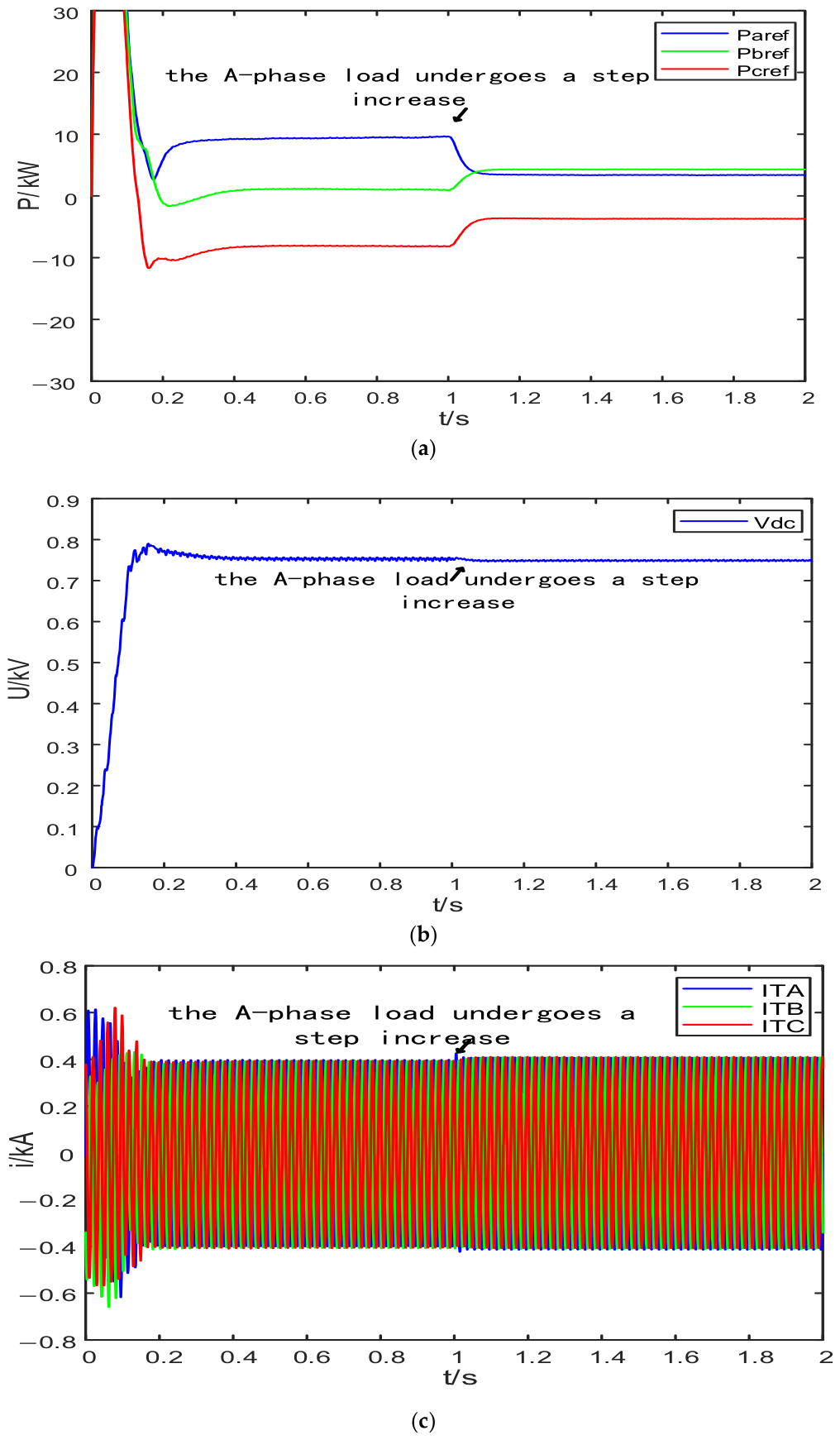
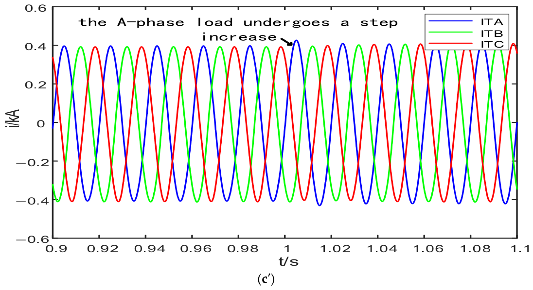
To further investigate the dynamic regulation capability of the proposed strategy under operating-point variations, a load-disturbance condition is applied by imposing a 6 kW increase in the equivalent Phase-A load at t = 1 s after the system reaches steady operation. Figure 13 shows the dynamic responses of the three-phase compensation power of VSC1, the DC-link voltage, and the three-phase current at Node 0 under the disturbance. As shown in Figure 13a, after the disturbance occurs, the three-phase compensation powers of VSC1 are rapidly readjusted, indicating that the proposed strategy can promptly correct the total compensation power and its phase-wise allocation according to load variations. As shown in Figure 13b, although the DC-link voltage experiences a short transient fluctuation, it quickly recovers and remains stable around the reference value, demonstrating that the common DC link maintains good stability under the disturbance condition. As shown in Figure 13c, the three-phase current at Node 0 returns to a balanced state after a transient adjustment, indicating that the proposed method can still effectively suppress head-end three-phase current unbalance under dynamic conditions.
Figure 13.
Dynamic responses under the Phase-A load-increase disturbance condition. (a) Three-phase compensation power of VSC1. (b) DC-link voltage. (c) Head-end three-phase currents. (c′) Enlarged view of the head-end three-phase currents.
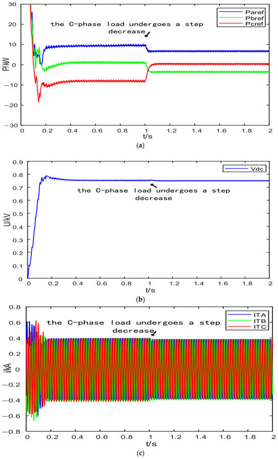
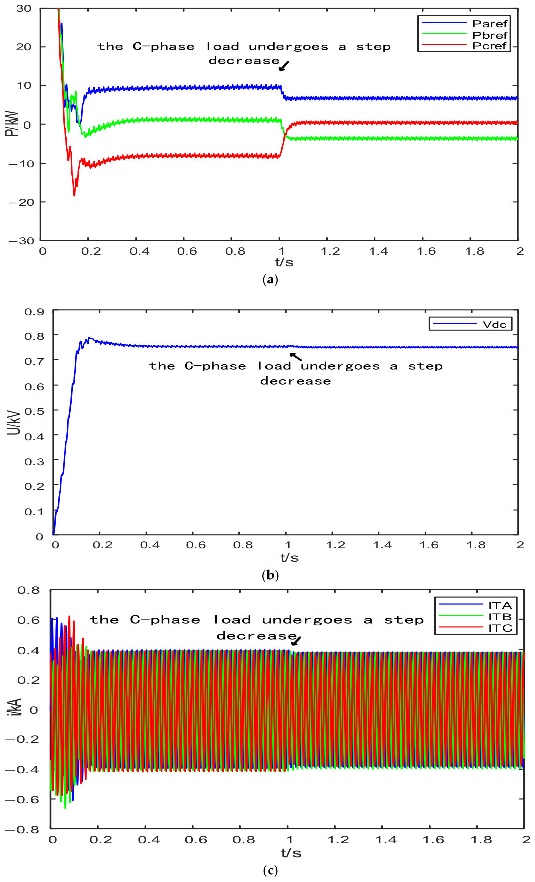
To further verify the adaptability of the proposed strategy under different load disturbance conditions, an additional Phase-C load-decrease case is considered. In this case, the equivalent Phase-C load is suddenly reduced by 6 kW at t = 1 s after the system reaches steady state.
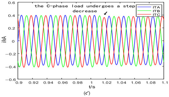
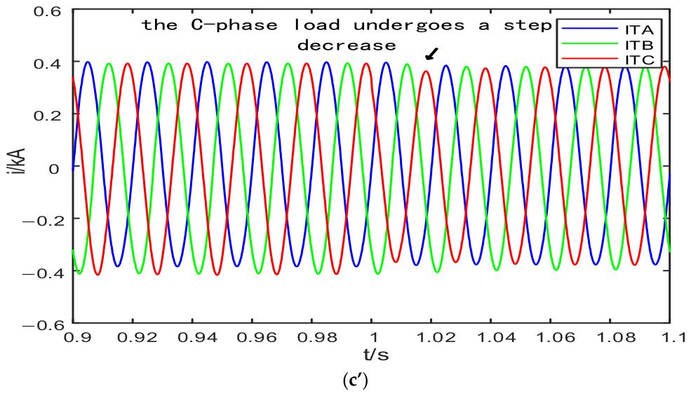
Figure 14 shows the dynamic responses of the three-phase compensation power of VSC1, the DC-link voltage, and the head-end three-phase currents under the Phase-C load-decrease disturbance condition. As shown in Figure 14a, when the Phase-C load decreases, the three-phase compensation powers of VSC1 are readjusted according to the changed phase-power unbalance condition. This indicates that the proposed strategy can update the phase-wise compensation power allocation in response to different disturbance directions. Figure 14b shows that the DC-link voltage only experiences a short transient fluctuation after the disturbance and then quickly returns to the reference value, demonstrating that the DC-link voltage loop can maintain the energy balance of the head-to-tail flexible interconnection system. As shown in Figure 14c, the head-end three-phase currents undergo a transient adjustment after the Phase-C load decrease and then return to a balanced state. The enlarged view in Figure 14c’ further confirms that the three-phase currents remain well balanced after the transient process. The results under both the Phase-A load-increase and Phase-C load-decrease conditions show that the proposed method is not limited to a single disturbance direction or a specific phase. Overall, the proposed DC-link-voltage-control-based phase-wise compensation strategy exhibits good dynamic regulation capability and operational stability under different load-disturbance conditions.
Figure 14.
Dynamic responses under the Phase-C load-decrease disturbance condition. (a) Three-phase compensation power of VSC1. (b) DC-link voltage. (c) Head-end three-phase currents. (c′) Enlarged view of the head-end three-phase currents.
To further quantify the dynamic regulation performance, the DC-link voltage recovery time is defined as the time required for the DC-link voltage to return to and remain within ±2% of its reference value after the load disturbance. According to Figure 13b and Figure 14b, the DC-link voltage recovers to the ±2% band of the 0.75 kV reference within approximately 0.1 s under both load-disturbance conditions. Meanwhile, the compensation powers of VSC1 are readjusted according to the changed phase-power unbalance and then reach new steady-state values without sustained oscillation. These results further confirm that the proposed strategy has satisfactory dynamic recovery capability and does not impose excessive compensation-power demand on the head-end converter during load disturbances.
5.5. Verification Under RL Load Condition
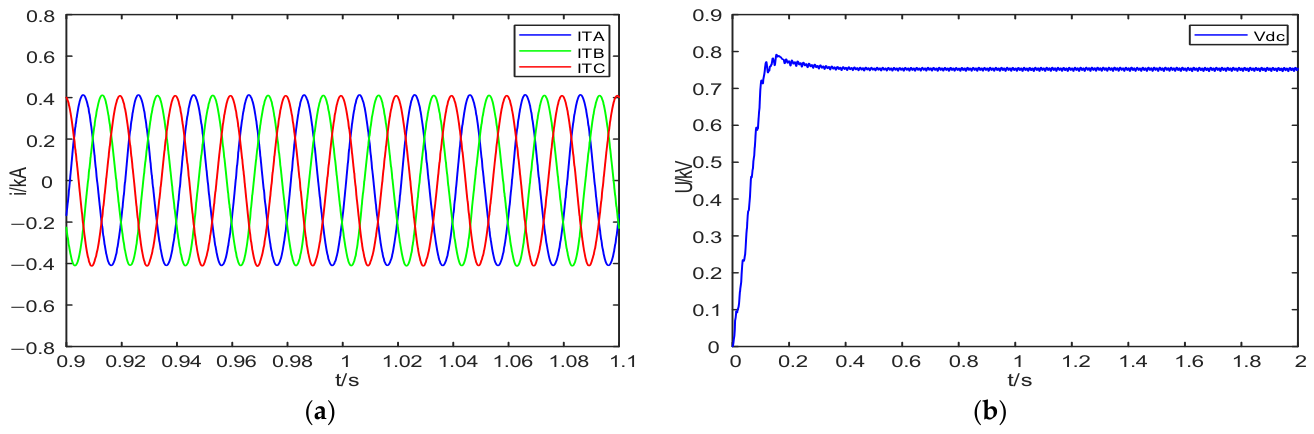
To further verify the applicability of the proposed compensation strategy under a more practical load condition, an RL load case is introduced in this section. In this case, a 7.27 mH inductor is connected in parallel with each phase load, so that each phase contains both resistive and inductive components. Compared with the purely resistive-load condition, the parallel inductive branches introduce reactive current components and cause phase shifts between the phase voltages and currents. Therefore, the power relationship and the current tracking process become more complicated. This case is used to evaluate whether the proposed DC-link-voltage-control-based phase-wise compensation strategy can still maintain effective compensation performance when inductive load components are included.
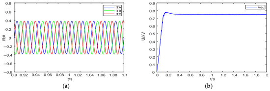
Figure 15 shows the compensation performance of the proposed method under the RL load condition. As shown in Figure 15a, the head-end three-phase currents become more balanced after the proposed strategy is activated, although the load contains inductive components. Figure 15b shows that the DC-link voltage remains stable around the reference value of 0.75 kV after the transient process, indicating that the outer DC-link voltage loop can still maintain the energy balance of the head-to-tail flexible interconnection system under the RL load condition.
Figure 15.
Compensation performance of the proposed method under the RL load condition. (a) Head-end three-phase currents. (b) DC-link voltage.
The quantitative comparison between the R load and RL load conditions is given in Table 5. Under the R load condition, the current unbalance index is reduced from 15.39% to 0.69%. Under the RL load condition, the current unbalance index is reduced from 15.39% to 1.04%. Compared with the purely resistive-load condition, the RL load condition introduces reactive current components and voltage-current phase shifts, which make the instantaneous power relationship and current tracking process more complex. This explains why the final current unbalance index under the RL load condition is slightly higher than that under the R load condition. Nevertheless, the proposed method still achieves effective unbalance mitigation, and the DC-link voltage remains stable around 0.75 kV. These results indicate that the outer DC-link voltage loop can maintain the energy balance of the head-to-tail interconnection system when inductive load components are included.
Table 5.
Compensation performance under R load and RL load conditions.
5.6. Additional Performance Evaluation
To further evaluate the influence of the proposed compensation strategy on current waveform quality and DC-link voltage stability, additional performance indices are analyzed in this section. Since the proposed method mainly focuses on fundamental-frequency three-phase current unbalance mitigation rather than harmonic suppression, the total harmonic distortion (THD) of the head-end three-phase currents is used to verify whether the compensation process introduces obvious harmonic deterioration. The THD values are calculated over the steady-state interval from 1.5 s to 2.0 s to avoid the influence of the start-up transient and load-disturbance transient processes.
As shown in Table 6, the THD values under the non-embedded condition are 0.56%, 0.47%, and 0.34% for phases A, B, and C, respectively. These values are relatively low because the head-end currents are mainly determined by the ideal source and equivalent loads. After the proposed converter-based compensation strategy is introduced, the THD values increase slightly due to the injection of compensation currents from VSC1. Under the R load condition, the THD values of phases A, B, and C are 2.22%, 2.57%, and 2.21%, respectively. Under the RL load condition, the corresponding THD values are 2.23%, 2.57%, and 2.24%, respectively. The slight increase in THD is mainly related to the PWM-based converter current injection process. Due to the finite switching frequency, current-loop bandwidth, and transient tracking error of the quasi-PR controller, small harmonic components may be introduced into the compensated head-end currents. Nevertheless, all THD values after compensation remain below 3%, indicating that the proposed method does not cause significant harmonic deterioration while mitigating the fundamental-frequency current unbalance. In addition, the THD values under the R load and RL load conditions are very close, indicating that the added inductive branches do not introduce significant harmonic components.
Table 6.
Additional performance indices under different operating conditions.
Overall, the additional performance evaluation shows that the proposed DC-link-voltage-control-based phase-wise compensation strategy can effectively mitigate head-end three-phase current unbalance while maintaining acceptable current waveform quality and DC-link voltage stability under different operating conditions.
5.7. Verification Under Equivalent Feeder-Impedance Conditions
To further evaluate the applicability of the proposed strategy when feeder impedance is considered, an equivalent feeder-impedance condition is considered in this subsection. A three-phase series RL branch is inserted between the transformer secondary side and the head-end access point of the LVTA. The equivalent parameters are selected according to the main feeder branch parameters listed in Appendix A. By aggregating four main feeder sections, the equivalent feeder resistance is obtained as , and the corresponding equivalent inductance is calculated as .
The neutral-conductor resistance is also considered to account for the loss caused by the neutral current. Since separate neutral-conductor parameters are not available, the neutral-conductor resistance is assumed to be the same as the phase-conductor resistance, namely . To further examine the robustness of the proposed method against feeder-parameter variations, a high feeder-impedance condition is also tested. In this condition, the equivalent feeder parameters are doubled and set to , , and . These cases are not intended to replace a complete node-by-node feeder model. Instead, they provide an equivalent verification of the influence of feeder voltage drop, line loss, neutral-current loss, and feeder-impedance variation on the proposed compensation strategy.
The total line loss of the equivalent feeder is calculated as
where and are the RMS currents flowing through the phase conductors, is the RMS neutral current, is the equivalent resistance of each phase conductor, and is the neutral-conductor resistance. The voltage unbalance index is calculated using the same maximum-deviation principle as the current unbalance index, and the neutral current is reported as an additional operating index.
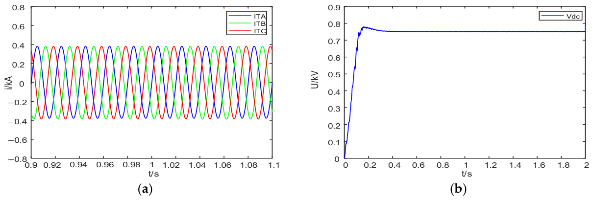
Figure 16 shows the compensation performance of the proposed method under the equivalent feeder-impedance condition. As shown in Figure 16a, after the proposed strategy is activated, the head-end three-phase currents remain effectively balanced even with the inserted feeder impedance. Figure 16b shows that the DC-link voltage remains stable around the reference value of 0.75 kV. These results indicate that the proposed DC-link-voltage-control-based phase-wise compensation strategy can still maintain stable current compensation when feeder voltage drop and neutral-current effects are considered.
Figure 16.
Compensation performance of the proposed method under the equivalent feeder-impedance condition. (a) Head-end three-phase currents. (b) DC-link voltage.
As shown in Table 7, after the equivalent feeder impedance is introduced, the proposed method still maintains a low head-end current unbalance index of 0.63%, while the voltage unbalance index is only 0.12%. The neutral current is limited to 2.71 A, indicating that the phase-wise compensation strategy can effectively suppress the neutral-current component caused by three-phase unbalance. Under the high feeder-impedance condition, the current unbalance index remains as low as 0.65%, and the DC-link voltage remains stable around 0.75 kV. Although the line loss increases from 8.38 kW to 15.46 kW due to the increased feeder resistance, the compensation performance is not significantly deteriorated. These results verify the robustness of the proposed method against feeder-impedance variations.
Table 7.
Performance comparison under equivalent feeder-impedance conditions.
6. Conclusions
To address head-end three-phase current unbalance and terminal power-quality deterioration caused by uneven three-phase load allocation in an LVTA, this paper proposes a DC-link-voltage-control-based phase-wise unbalanced power compensation strategy for an internal head-to-tail flexible interconnection structure. A switching-cycle averaged model of the three-phase four-leg converter is established, and a control-oriented equivalent LVTA model is developed in MATLAB/Simulink to verify the proposed strategy. The main conclusions are summarized as follows.
- (1)
- The established switching-cycle averaged model provides the theoretical basis for phase-wise current control of the three-phase four-leg converter. Under the assumptions of small DC-link voltage fluctuation and approximately symmetrical converter parameters, the duty-cycle variable of each phase leg mainly affects the corresponding phase current, which supports the design of phase-wise quasi-PR current control without explicit sequence decomposition. Meanwhile, the possible system-level coupling through the common DC link and the fourth-leg/neutral-current path is clarified.
- (2)
- The proposed compensation strategy uses the outer DC-link voltage loop to generate the total active compensation power and allocates it among the three phases according to the measured phase-power unbalance of the LVTA. In this way, DC-link voltage regulation and AC-side phase-wise compensation power generation are incorporated into a unified control framework. Under the steady-state unbalanced condition, the head-end three-phase current unbalance index is reduced from 15.39% to 0.69%, indicating that the proposed strategy can effectively mitigate the head-end current unbalance.
- (3)
- Compared with the conventional positive-, negative-, and zero-sequence compensation method, the proposed method achieves effective unbalance mitigation while avoiding explicit sequence extraction and simplifying the compensation-current generation process. The proposed method achieves a 95.52% reduction in the current unbalance index, which is higher than that of the conventional sequence-component-based method. The RL load condition further verifies that the proposed strategy can maintain effective compensation performance when the load contains inductive components, with the current unbalance index reduced to 1.04%. Moreover, the THD values of the compensated currents remain below 3%, indicating that the proposed method does not cause obvious harmonic deterioration.
- (4)
- Under load-disturbance conditions, the proposed strategy can readjust the total compensation power and phase-wise compensation references according to the changed power-unbalance condition. The head-end three-phase currents return to a balanced state after the transient process, and the DC-link voltage remains stable around 0.75 kV, demonstrating satisfactory dynamic adaptability. In addition, under the equivalent feeder-impedance condition, the current unbalance index is maintained at 0.63%, the voltage unbalance index is 0.12%, and the RMS neutral current is limited to 2.71 A. Under the high feeder-impedance condition, the current unbalance index remains 0.65%, indicating that the proposed method has acceptable robustness against feeder-impedance variations.
Overall, the proposed method provides a feasible control framework for three-phase unbalance mitigation in flexible low-voltage transformer areas. Nevertheless, the present validation is still based on a control-oriented simulation model. More detailed feeder modeling and experimental or hardware-in-the-loop verification will be further considered in future work.
Author Contributions
Conceptualization, M.X. and H.Z.; methodology, M.X.; software, M.X.; validation, M.X.; formal analysis, M.X.; investigation, M.X.; resources, H.Z.; data curation, M.X.; writing—original draft preparation, M.X.; writing—review and editing, M.X. and H.Z.; visualization, M.X.; supervision, H.Z.; project administration, H.Z. All authors have read and agreed to the published version of the manuscript.
Funding
This research was funded by the National Natural Science Foundation of China, grant number 62461008. The APC was funded by the authors.
Data Availability Statement
The original contributions presented in this study are included in the article. Further inquiries can be directed to the corresponding author.
Conflicts of Interest
The authors declare no conflict of interest.
Appendix A
Table A1.
Node-wise load and PV capacity data in the LVTA simulation model.
Table A2.
Main branch line parameters of the LVTA.
References
- Ma, K.; Fang, L.; Kong, W. Review of distribution network phase unbalance: Scale, causes, consequences, solutions, and future research directions. CSEE J. Power Energy Syst. 2020, 6, 3. [Google Scholar] [CrossRef] [Scilit]
- Rafi, F.H.M.; Hossain, M.J.; Rahman, M.S.; Taghizadeh, S. An overview of unbalance compensation techniques using power electronic converters for active distribution systems with renewable generation. Renew. Sustain. Energy Rev. 2020, 125, 109812. [Google Scholar] [CrossRef] [Scilit]
- Pinthurat, W.; Hredzak, B.; Konstantinou, G.; Fletcher, J. Techniques for compensation of unbalanced conditions in LV distribution networks with integrated renewable generation: An overview. Electr. Power Syst. Res. 2023, 214, 108932. [Google Scholar]
- Haque, M.M.; Wolfs, P. A review of high PV penetrations in LV distribution networks: Present status, impacts and mitigation measures. Renew. Sustain. Energy Rev. 2016, 62, 1195–1208. [Google Scholar] [CrossRef] [Scilit]
- Shahnia, F.; Wolfs, P.J.; Ghosh, A. Voltage unbalance reduction in low voltage feeders by dynamic switching of residential customers among three phases. IEEE Trans. Smart Grid 2014, 5, 1318–1327. [Google Scholar] [CrossRef] [Scilit]
- Bao, G.; Ke, S. Load transfer device for solving a three-phase unbalance problem under a low-voltage distribution network. Energies 2019, 12, 2842. [Google Scholar] [CrossRef] [Scilit]
- Pereira, O.; Quirós-Tortós, J.; Valverde, G. Phase rebalancing of distribution circuits dominated by single-phase loads. IEEE Trans. Power Syst. 2021, 36, 6. [Google Scholar] [CrossRef] [Scilit]
- Xiao, J.; Wang, Y.; Luo, F.; Bai, L.; Gang, F.; Huang, R.; Jiang, X.; Zhang, X. Flexible distribution network: Definition, configuration, operation, and pilot project. IET Gener. Transm. Distrib. 2018, 12, 4492–4498. [Google Scholar] [CrossRef] [Scilit]
- Cao, W.; Wu, J.; Jenkins, N.; Wang, C.; Green, T. Benefits analysis of soft open points for electrical distribution network operation. Appl. Energy 2016, 165, 36–47. [Google Scholar] [CrossRef] [Scilit]
- Fuad, K.S.; Hafezi, H.; Kauhaniemi, K.; Laaksonen, H. Soft open point in distribution networks. IEEE Access 2020, 8, 210550–210565. [Google Scholar] [CrossRef] [Scilit]
- Jiang, X.; Zhou, Y.; Ming, W.L.; Yang, P.; Wu, J. An overview of soft open points in electricity distribution networks. IEEE Trans. Smart Grid 2022, 13, 1899–1910. [Google Scholar] [CrossRef] [Scilit]
- Li, P.; Ji, H.; Wang, C.; Zhao, J.; Song, G.; Ding, F.; Wu, J. Optimal operation of soft open points in active distribution networks under three-phase unbalanced conditions. IEEE Trans. Smart Grid 2017, 10, 380–391. [Google Scholar] [CrossRef] [Scilit]
- Pidancier, T.; Bozorg, M.; Roggo, D.; Favre-Perrod, P.; Carpita, M. 15 kVA three-phase low-voltage SOP prototype laboratory tests results. Energies 2020, 13, 3895. [Google Scholar]
- Yu, G.; Xu, J.; Wu, G.; Zhang, Z.; Zhao, D. Improved virtual synchronous generator control strategy for the flexible interconnection system in distribution transformer areas. Electr. Power Syst. Res. 2023, 214, 108877. [Google Scholar] [CrossRef] [Scilit]
- Feng, Q.; Li, J.; Zhou, J.; Xu, Y.; He, Q.; Gao, Y. A coordinated power quality improvement control strategy for AC/DC hybrid distribution networks based on three-phase four-leg flexible interconnection converter. Front. Energy Res. 2025, 13, 1602269. [Google Scholar] [CrossRef] [Scilit]
- Kim, G.H.; Hwang, C.; Jeon, J.H.; Ahn, J.-B.; Kim, E.-S. A novel three-phase four-leg inverter based load unbalance compensator for stand-alone microgrid. Int. J. Electr. Power Energy Syst. 2015, 65, 70–75. [Google Scholar]
- Tan, K.H.; Lin, F.J.; Chen, J.H. A three-phase four-leg inverter-based active power filter for unbalanced current compensation using a Petri probabilistic fuzzy neural network. Energies 2017, 10, 2005. [Google Scholar] [CrossRef] [Scilit]
- Buła, D.; Jarek, G.; Michalak, J.; Zygmanowski, M. Control method of four wire active power filter based on three-phase neutral point clamped T-type converter. Energies 2021, 14, 8427. [Google Scholar] [CrossRef] [Scilit]
- Kim, T.G.; An, C.G.; Yi, J.; Won, C.Y. Current compensation method in a distribution system based on a four-leg inverter under unbalanced load conditions using an artificial neural network. Energies 2024, 17, 1325. [Google Scholar] [CrossRef] [Scilit]
- Ninad, N.A.; Lopes, L. Per-phase vector control strategy for a four-leg voltage source inverter operating with highly unbalanced loads in stand-alone hybrid systems. Int. J. Electr. Power Energy Syst. 2014, 55, 449–459. [Google Scholar] [CrossRef] [Scilit]
- Lliuyacc, R.; Mauricio, J.M.; Gomez-Exposito, A.; Savaghebi, M.; Guerrero, J.M. Grid-forming VSC control in four-wire systems with unbalanced nonlinear loads. Electr. Power Syst. Res. 2017, 152, 249–256. [Google Scholar] [CrossRef] [Scilit]
- Jiang, H.; Pan, H.; Shang, B. An individual sequencing control strategy for three-phase four-leg inverter under unbalanced loads. Energy Rep. 2023, 9, 256–266. [Google Scholar]
- Kuzmin, S.V.; Zavalov, A.; Kuzmin, R.S.; Menshikov, V.A. Increase of reactive power compensation efficiency on the basis of individual phase compensation devices. J. Sib. Fed. Univ. Eng. Technol. 2020, 13, 14–24. [Google Scholar] [CrossRef] [Scilit]
- Ning, B.; Zhang, R.; Yuan, X.; Cai, Y.; Zhang, C.; Lu, Z. Flexible transformer-area unbalance compensation strategy based on phase-wise power control. Power Syst. Clean Energy 2025, 41, 64–72. [Google Scholar]

Disclaimer/Publisher’s Note: The statements, opinions and data contained in all publications are solely those of the individual author(s) and contributor(s) and not of MDPI and/or the editor(s). MDPI and/or the editor(s) disclaim responsibility for any injury to people or property resulting from any ideas, methods, instructions or products referred to in the content. |
© 2026 by the authors. Licensee MDPI, Basel, Switzerland. This article is an open access article distributed under the terms and conditions of the Creative Commons Attribution (CC BY) license.