


Abstract
To investigate the dynamic characteristics of key parameters in a piston gravity energy-storage system, an experimental system for novel piston gravity energy storage is designed and developed. Firstly, the structure and working principle of the piston gravity energy-storage system are analyzed. Adopting a modular modeling approach, the system is divided into four core modules, and the piston motion, vertical cylinder chamber pressure, hydraulic actuator, and turbine power models are established. Subsequently, a case study simulation is conducted on the piston gravity energy-storage system to model its dynamic characteristics during discharge conditions, analyzing the variation patterns of key parameters such as the chamber pressure, flow rate, and output power within the system. Finally, the experimental system integrates a digital controller with proportional–integral power regulation and an automatic mode switching logic to enable the constant power closed-loop control, with real-time acquisition of the chamber height, pressure, flow rate, and electrical parameters. The dynamic responses of various system parameters are analyzed. Experimental results indicate that under constant power charging and discharging conditions, the height of the upper chamber exhibits a linear trend, the pressure in the lower chamber is inversely proportional to the height of the upper chamber, and the flow rate remains stable with charging and discharging power. Neglecting energy losses of the pump and hydraulic turbine and only considering friction and hydraulic losses, the charge–discharge efficiency of the energy-storage experimental system is 65%.
1. Introduction
Under the goal of carbon peak and carbon neutrality, offshore wind power has emerged as a crucial renewable energy source in China, playing a critical role in energy structure transition [1,2]. However, the large-scale grid integration of offshore wind power, characterized by strong stochasticity and volatility in recent years, which has reduced the adjustability and flexibility of power systems, intensifies challenges in maintaining the balance of power and energy between the source and load [3,4,5]. Energy storage is widely regarded as a key technology for mitigating power fluctuations and enhancing renewable energy-accommodation capacity.
Multiple energy-storage technologies are currently available, including electrochemical energy storage, pumped storage, hydrogen energy storage, thermal energy storage, compressed air energy storage, and gravity energy storage [6,7]. Owing to its modularity and deployment flexibility, electrochemical energy storage can serve a wide range of applications, from household energy storage to grid-side frequency regulation; however, it still faces lifespan limitations caused by battery degradation and safety hazards such as thermal runaway [8]. Pumped storage dominates the energy-storage landscape because of its long service life and low levelized cost of energy, but it is heavily dependent on the geographic availability of upper and lower reservoirs and has localized ecological impacts [9]. Thermal energy storage suffers from irreversible losses during energy conversion, resulting in charge–discharge efficiency that is generally lower than that of other storage technologies [10]. Compressed air energy storage has attained relatively high technological maturity, but conventional approaches rely on caverns or salt caverns for air storage and remain constrained by low efficiency [11]. By contrast, the piston gravity energy-storage system features a long service life, inherent safety, siting flexibility, environmental friendliness, and high charge–discharge efficiency, making it a novel energy storage technology with outstanding complementary advantages [12].
Current research on piston gravity energy storage primarily focuses on system modeling and performance optimization. Berrada et al. [13] established a dynamic model based on mass conservation to predict the volumes and pressures of the upper and lower chambers of the system tower. Emrani et al. [14] investigated structural behavior and flow characteristics under various operating conditions, revealing that system stability depends on pipe wall thickness. Tan et al. [15] incorporated hydraulic oil bulk modulus theory to refine the mathematical model and analyzed performance variations across design parameters. Emrani et al. [16] utilized a multi-domain simulation tool to analyze the impact of scale on the charge–discharge efficiency, demonstrating superiority over other mechanical energy-storage systems at large capacity. Emrani et al. [17] designed a steel-wire-rope-driven piston gravity energy storage system, developing a simulation model that achieved efficiency gains. He et al. [18] optimized parameters for a novel compressed air piston gravity energy-storage system, enhancing the charge–discharge efficiency and energy density. In terms of applications, Taheri et al. [19] incorporated gravity energy storage into a green combined cooling and power system, which offers advantages in cost effectiveness. Emrani et al. [20] proposed a renewable-gravity energy-storage system, and the results demonstrated that the proposed system is capable of balancing energy supply and demand.
Although piston gravity energy-storage systems have attracted widespread attention from researchers, there is relatively little research on experimental systems. Existing experimental studies have mainly focused on slope and vertical gravity energy-storage systems. Wang et al. [21] investigates the influence of key parameters on the overall efficiency of a chain-driven slope gravity energy-storage system, optimizing parameters to improve system efficiency and conducting experimental verification based on a prototype. Furthermore, Wang et al. [22] proposes a synchronous generator starting method based on mass block traction to meet the frequent start–stop requirements of gravity energy storage. Wang et al. [23] and Gao et al. [24] respectively developed energy-efficiency-analysis models for slope and vertical gravity energy-storage systems and verified the feasibility of the proposed models through experimental prototypes.
To further investigate the dynamic characteristics of piston gravity energy-storage systems, this paper designs an experimental system. Firstly, the structural composition and working principle of a novel piston gravity energy-storage system are analyzed. The system is divided into four core modules, for which the piston motion model, the tower chamber pressure model, the hydraulic actuator model, and the hydro-turbine unit power model are established, respectively. Secondly, a simulation model of the system is constructed using the MATLAB/Simulink platform (The version is MATLAB 2019B), and the dynamic response characteristics of the system’s key parameters are analyzed. Finally, an experimental system for piston gravity energy storage is designed and developed. Sensors are employed to acquire system parameters, and a software program is developed to realize closed-loop power control of the system.
2. Model of Novel Piston Gravity Energy-Storage System
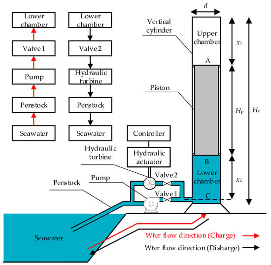
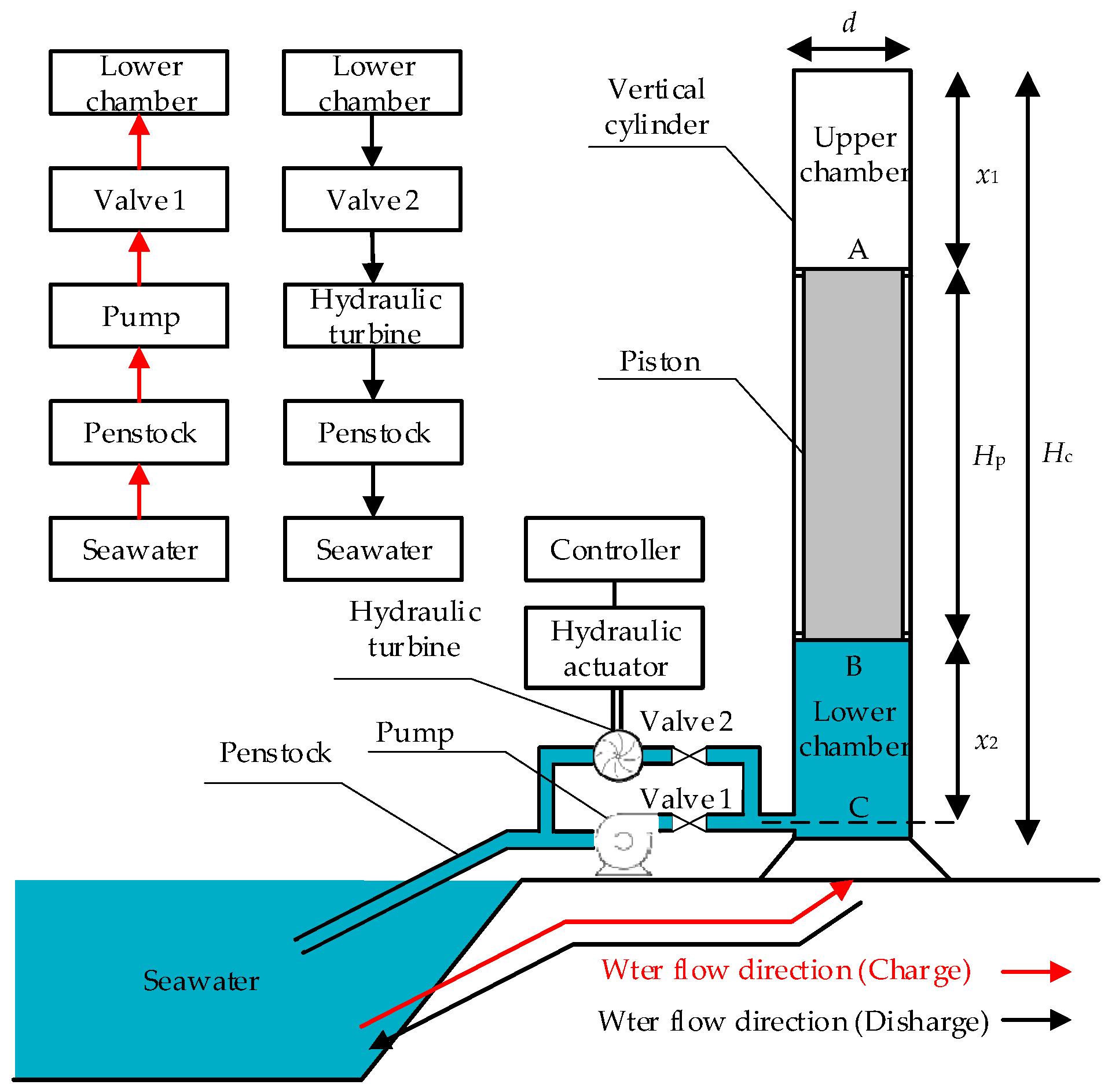
To address the issues of low utilization rates in offshore wind power and difficulties in grid integration, a piston gravity energy-storage system is proposed. The system utilizes the ocean as a natural lower reservoir, offering advantages such as a small footprint and environmental friendliness, and is suitable for applications such as coastal renewable energy hubs and island microgrids. The working medium of the energy-storage system is seawater, and its specific structure is shown in Figure 1. The system comprises a piston, a vertical cylinder, penstocks, valves, a pump, a hydraulic turbine, and its controller. The piston divides the vertical cylinder into an upper chamber and a lower chamber. During charging conditions, valve 1 is open and valve 2 is closed. The pump delivers seawater through the penstock into the lower chamber, driving the piston upward in the vertical direction and converting electrical energy into gravitational potential energy. During discharging conditions, valve 1 is closed and valve 2 is open. The piston descends vertically under the influence of gravity, forcing the seawater in the lower chamber to flow through the penstock, driving the hydraulic turbine to rotate and generate electricity, thereby converting gravitational potential energy into electrical energy.
Figure 1.
Structure of novel piston gravity energy-storage system.
2.1. Piston Motion Model
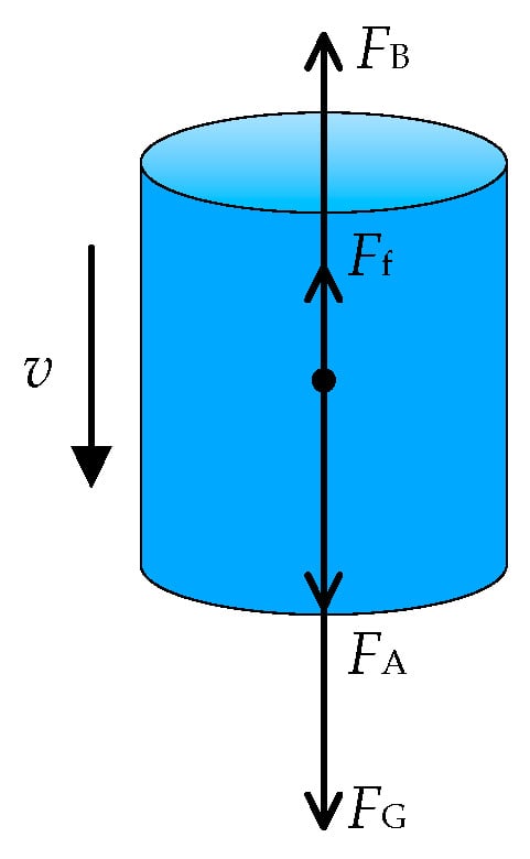
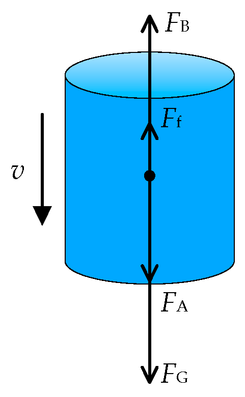
The piston is located inside the vertical cylinder, and its motion is determined by the combined effects of its own weight, the pressure in the upper chamber, the supporting force from the lower chamber, and the friction against the cylinder wall. Under discharge conditions, the force analysis is shown in Figure 2, and the equation governing the piston’s motion is calculated by Equation (1).
where m and a represent the mass and acceleration of the piston, FA is the pressure in the upper chamber, FB is the supporting force in the lower chamber, and FG is the gravitational force acting on the piston. The velocity v, acceleration a, and displacement xp of the piston are calculated by Equation (2).
where pA is the pressure at point A in the upper chamber. As the top of the upper chamber is not fully sealed, pA is taken as the standard atmospheric pressure; pB is the pressure generated by the water in the lower chamber under compression; S is the cross-sectional area of the piston; g is the gravitational acceleration. The friction force Ff consists of the initial friction Fe caused by the pre-compression of the sealing ring and the friction increment Fp induced by the pressure difference between the upper and lower chambers, as shown in Equation (3) [25].
where μ is the friction coefficient, τ is the pre-compression ratio of the sealing ring, E is the elastic modulus of the sealing ring material, and Ds is the outer diameter of the sealing ring, representing the diameter of the outermost circumference of the seal ring. ds is the cross-sectional diameter of the sealing ring, and α is the Poisson’s ratio of the sealing ring, representing the absolute value of the ratio of transverse strain to axial strain.
Figure 2.
Force analysis diagram of piston.
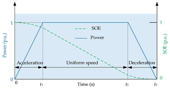
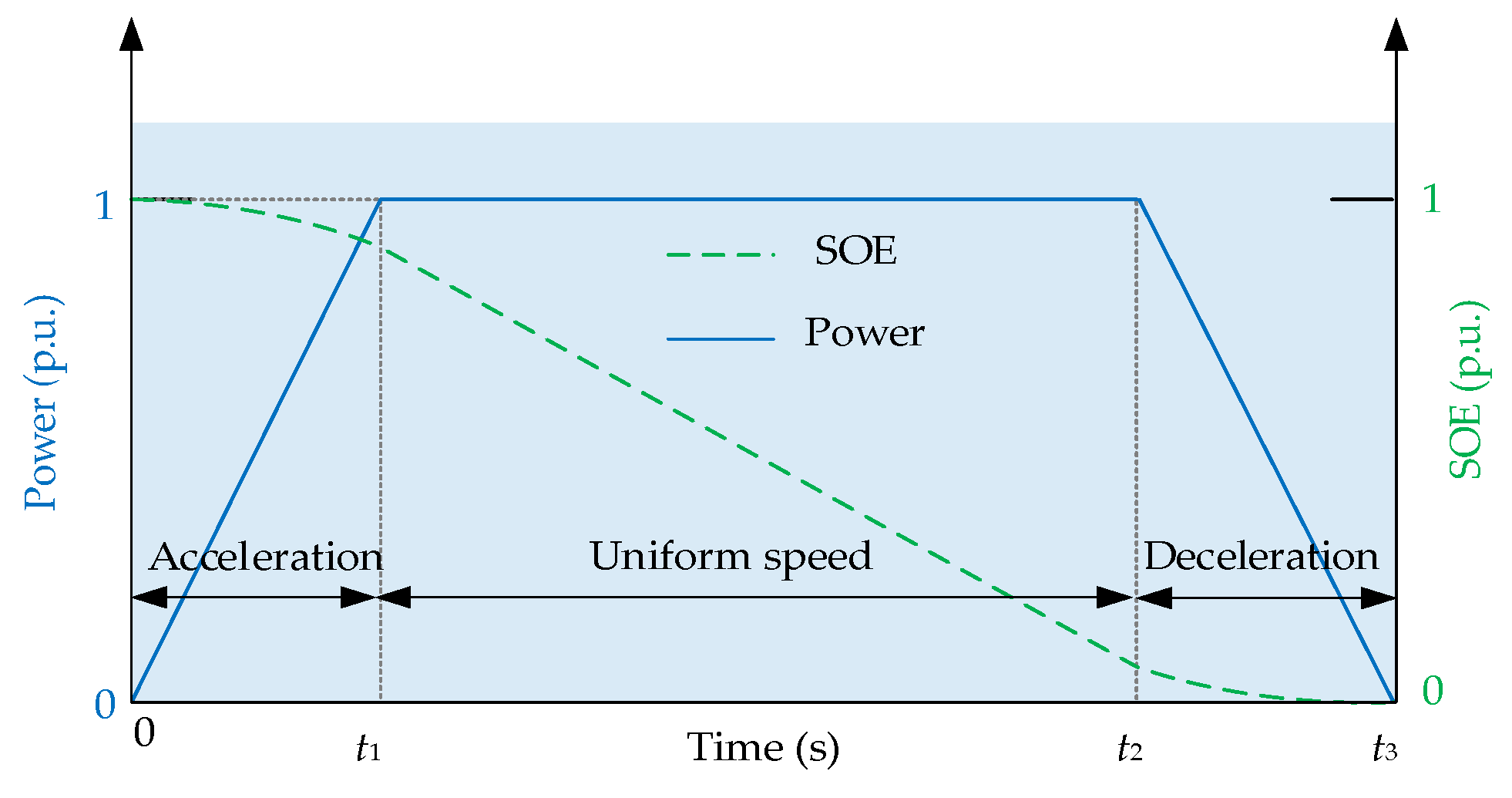
Due to the inertia of the piston, its motion involves three distinct phases: acceleration, uniform speed, and deceleration. As shown in Figure 3, the initial state of energy (SOE) of the gravity energy-storage system is set to 1. Under discharge conditions, the piston starts accelerating downward from rest, reaches its rated speed at time t1 at the end of the acceleration phase, and then operates at a constant speed during the uniform speed period from t1 to t2. During this period, the system discharges at rated power, and the SOE continuously decreases. After time t2 at the end of the uniform speed phase, the piston enters the deceleration phase until it comes to a complete stop at time t3 at the end of the deceleration phase, marking the end of the discharge process.
Figure 3.
Schematic diagram of power and SOE change curves.
2.2. Vertical Cylinder Chamber Pressure Model
The piston motion is affected by the pressure in the upper chamber and the supporting force from the lower chamber, with the latter being the dominant factor. When the piston descends at a constant velocity, the pressure at point B in the lower chamber remains unchanged, and the piston is in force equilibrium. During the discharge process, based on Newton’s second law, the force equation is shown in Equation (4).
Under discharge conditions, Ff and FB are in the same direction. According to the formula (FB = pBS), Equation (4) determines the pressure pBN in the lower chamber under downward piston motion at constant velocity. As the piston compresses the seawater in the lower chamber to form high pressure, the seawater is supposed to be treated as a compressible liquid. The pressure at point B in the lower chamber pB is calculated by Equation (5) [26].
where K is the bulk modulus of the seawater, and VBN is the volume of the lower chamber at pressure pBN, which is shown in Equation (6).
where Hc is the vertical cylinder height, Hp is the piston height, and q is the flow rate. The pressure pC at point C results from the combined effect of pressure exerted by the piston on seawater and gravity of the seawater in the lower chamber, as shown in Equation (7).
where ρ is the seawater density.
2.3. Hydraulic Actuator Model
The hydraulic actuator converts the electrical signal from the controller into a mechanical displacement signal. In the hydraulic turbine control, a main servomotor and an auxiliary servomotor are usually adopted to regulate the guide vane opening. By neglecting the auxiliary servomotor, the transfer function Gs(s) of the actuator is shown in Equation (8) [27].
where y(s) is the guide vane opening, u(s) is the controller output signal, and Ty is the servo time constant.
2.4. Hydraulic Turbine Power Model
Under discharge conditions, valve 1 remains closed while valve 2 actuates, and the hydraulic turbine is in operation. Its power model is shown in Equation (9) [28].
where h is the effective head of the hydraulic turbine; ht is the total head of the hydraulic turbine; hloss is the hydraulic loss in the penstock; Tw is the water time constant; Pd is the discharge power of the hydraulic turbine; η is the efficiency of the hydraulic turbine.
The total head ht of the hydraulic turbine is directly proportional to the pressure at point C in the lower chamber, as calculated by Equation (10).
hloss represents the hydraulic loss in the penstock, which is primarily influenced by the pipe loss coefficient, pipe length, and flow rate, and is calculated by Equation (11):
where ε is the pipe loss coefficient, and L is the length of the penstock.
3. Performance Evaluation Indicators and Case Simulation
3.1. Performance Evaluation Indicators
Stored energy Eg is defined as the product of the piston’s weight and the maximum displacement, as shown in Equation (12):
Energy density ρe is defined as the ratio of the total stored energy Eg to the total volume of the vertical cylinder and penstock, as shown in Equation (13):
where V is the volume of the vertical cylinder, and Vpen represents the volume of the penstock.
During the charge and discharge processes of the piston gravity energy-storage system, the system must overcome the friction losses between the piston and the vertical cylinder inner wall, as well as the hydraulic losses in the penstock. The charge–discharge efficiency ηg is defined as the ratio of the discharged energy Ed to the charged energy Ec, as shown in Equation (14):
3.2. Case Simulation
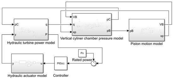
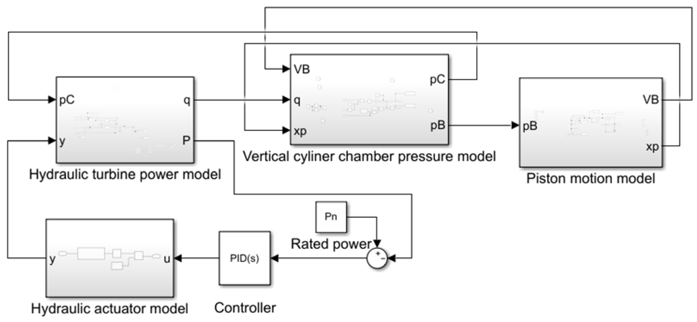
The model parameters of the piston gravity energy-storage system exhibit strong interdependence. The piston displacement and velocity are jointly governed by hydraulic turbine flow rate and pressure at point B in the lower chamber, whereas the turbine unit power is constrained by the water head and flow rate. A simulation model of the piston gravity energy storage system is established on the Matlab/Simulink platform, as shown in Figure 4, with the system parameters summarized in Table 1. The data in Table 1 are primarily derived from Reference [15]. The energy-storage system has a power of 85 kW, and the turbine efficiency is 90%. The cylinder height is 20 m; the piston height is half that of the cylinder, and the piston diameter is equal to its height. The bulk modulus K of seawater is a standard physical constant, taken as 2.2 GPa.
Figure 4.
Simulation model of piston gravity energy-storage system.
Table 1.
Parameters of piston gravity energy-storage system.
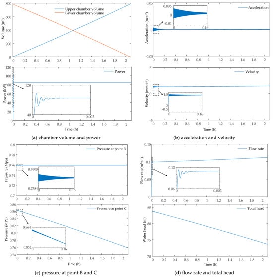
The piston is initially positioned at the top of the tower, and the simulation time is 2.15 h. The dynamic response process of the piston gravity energy-storage system is shown in Figure 5. Specifically, Figure 5a presents the dynamic responses of the upper and lower chamber volumes along with the output power. As the piston descends, it forces water out of the lower chamber, causing the lower chamber volume to decrease from 785.43 to 0 m3, while the upper chamber volume increases linearly to 785.43 m3. During the initial phase of the dynamic response, the opening of the guide vanes causes fluctuations in the hydraulic turbine flow due to the inertia of the water flow, resulting in oscillations in the output power. Once the system enters the steady-state phase, the piston is in a state of equilibrium, with the output power stabilizing at 85 kW and a response time of 5.4 s.
Figure 5.
Dynamic response process of piston gravity energy-storage system.
Figure 5b shows the dynamic responses of the piston acceleration and velocity. The initial fluctuations in acceleration are caused by the impact of the water flow resulting from the opening of the guide vanes, which causes pressure fluctuations at point B in the lower chamber and leads to an imbalance in the forces acting on the piston. Thereafter, the piston’s acceleration stabilizes at around 0 m·s−2, whilst its velocity rises from 0 to 1.5 mm·s−1 and remains constant, indicating that the system has entered a phase of uniform descent.
Figure 5c presents the pressure variations at points B and C in the lower chamber. After initial fluctuations, the pressure at point B stabilizes at 0.76 MPa; point C bears the additional weight of the water in the lower chamber, and its pressure decreases as the height of the lower chamber decreases, specifically falling from 0.86 MPa to 0.76 MPa.
Figure 5d shows the responses of the flow rate and total water head. Due to the inertia of the water flow, the flow rate fluctuates during the initial phase of the dynamic response. As the system employs constant power control, the pressure at point C in the lower chamber decreases, causing the flow rate to rise to 0.12 m3·s−1; given that the total head is positively correlated with the pressure at point C in the lower chamber, the total head decreases from 83.72 m to 74.41 m. Collectively, the model accurately describes the dynamic motion process and energy-transfer characteristics of the system and effectively characterizes the operational behavior of the piston gravity energy-storage system.
4. Development of Experimental System
To further investigate the dynamic response characteristics of the system, a piston gravity energy-storage experimental system is constructed. Constrained by experimental conditions, a marine environment is simulated using an acrylic water tank. To facilitate power measurement during charging and discharging processes, the pump and hydraulic turbine are operated at constant voltages.
4.1. Design of the Experimental System
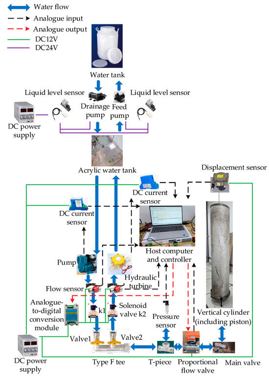
The piston gravity energy-storage system can be essentially regarded as a piston-cylinder system. Therefore, the mechanical structure of the experimental system is designed based on the piston-cylinder system, with further improvements to satisfy the expandability requirements of subsequent experiments. The structure of the piston gravity energy-storage experimental system is shown in Figure 6.
Figure 6.
Experimental system structure of piston gravity energy storage.
To achieve real-time monitoring during charging and discharging conditions, the piston position, pressure, flow rate, and power parameters need to be acquired synchronously. Since the pressure at point B in the lower chamber is difficult to measure, the pressure at point C is actually measured in the experiments and used as the lower chamber pressure. The experimental system implements signal acquisition and closed-loop control through a controller, changing the system operating mode in real time as required. The experimental parameters of the energy-storage system are as follows: vertical cylinder height is 1.2 m, piston height is 0.54 m, piston diameter is 0.25 m, piston mass is 185 kg, charging time is 151 s, and discharging time is 351 s.
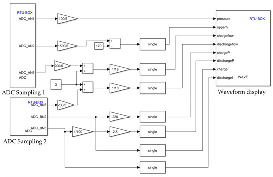
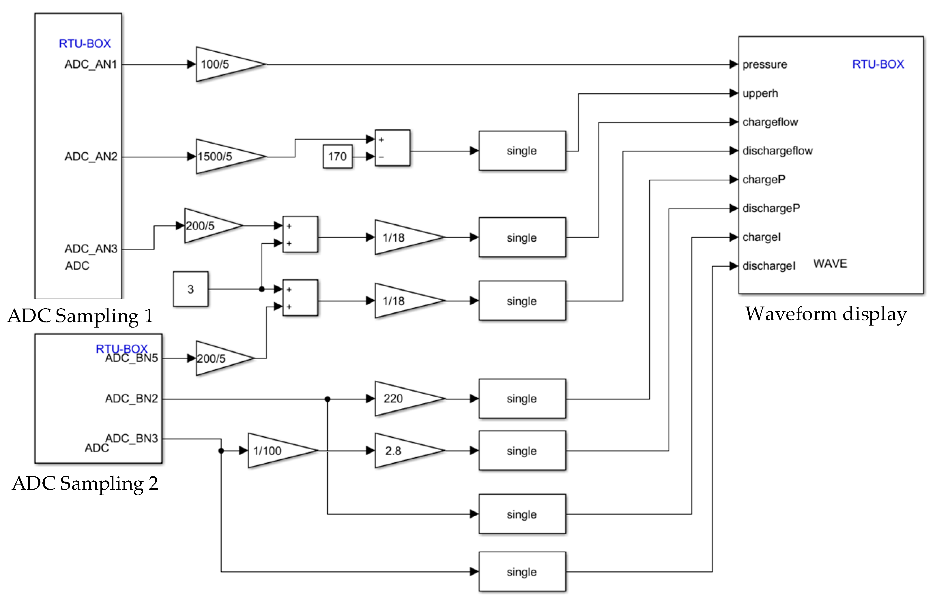
The experimental system adopts the Rtunit Studio 2023 software to achieve sensor data acquisition, processing, display, and control. Paired with the RTU-BOX201 digital controller, the software supports the conversion of Simulink models into C language programs, which can be compiled and downloaded. In addition, it enables real-time parameter modification, waveform observation, and data export. The data-acquisition and processing procedure is shown in Figure 7. The RTU-BOX is equipped with 24 ADC sampling channels, featuring 16-bit conversion resolution and a sampling rate of 2 kHz, with an input voltage range of −10 V to +10 V. Due to the inherent accuracy limitations of the sensors, the acquired data may fluctuate within a certain range.
Figure 7.
Data-acquisition and processing procedure.
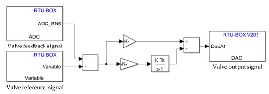
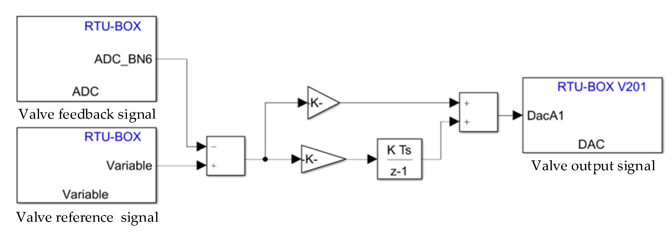
Regarding system control, PI control features a simple structure and excellent stability, making it widely adopted in industrial automation applications. By leveraging the cooperative effect of its proportional and integral actions, it effectively eliminates steady-state errors in flow control. The proportional flow valve control procedure is shown in Figure 8. Constant power discharge is achieved indirectly by adjusting the proportional flow valve, with the PI control parameters initially determined using the Ziegler–Nichols step response method and subsequently optimized through multiple iterative experiments, resulting in the final control parameters Kp and Ki being set at 0.6 and 0.4, respectively.
Figure 8.
Proportional flow valve control procedure.
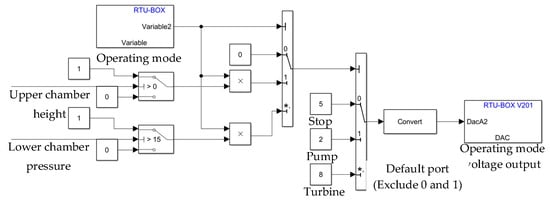
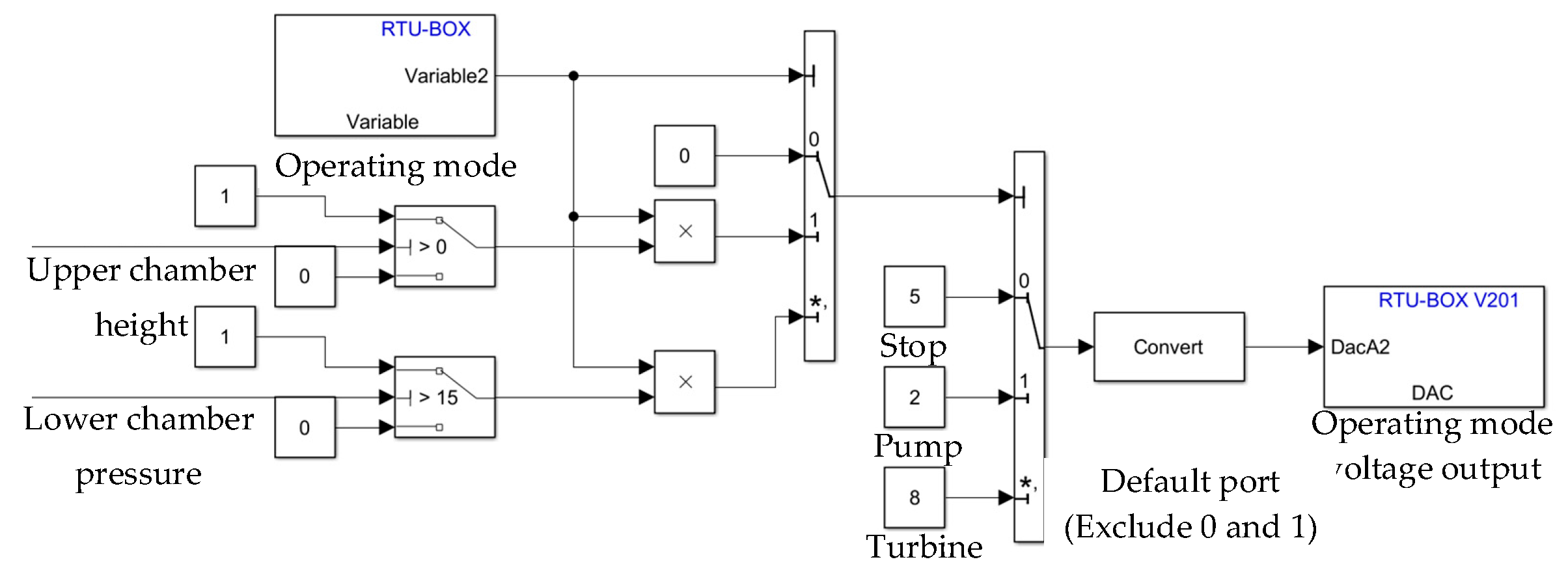
To switch the operating modes of the piston gravity energy-storage system, an analog-to-switch module is employed to control solenoid valves k1 and k2. The module changes the operation mode according to the input voltage as follows: when the voltage is below 3 V, the system operates in charging mode, solenoid valve k1 at the pump outlet is energized, and solenoid valve k2 at the turbine inlet is closed; when the voltage exceeds 7 V, the system enters discharging mode, with k1 open and k2 closed; when the voltage lies between 3 V and 7 V, the system is in stop mode, and both solenoid valves are de-energized. Additionally, the system automatically closes the solenoid valves based on signals from the displacement and pressure sensors, indicating that charging or discharging has been completed. The mode switching procedure is shown in Figure 9.
Figure 9.
System operation mode-switching procedure.
4.2. Analysis of Experimental Results
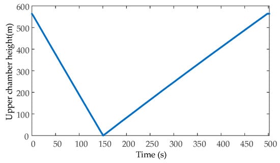
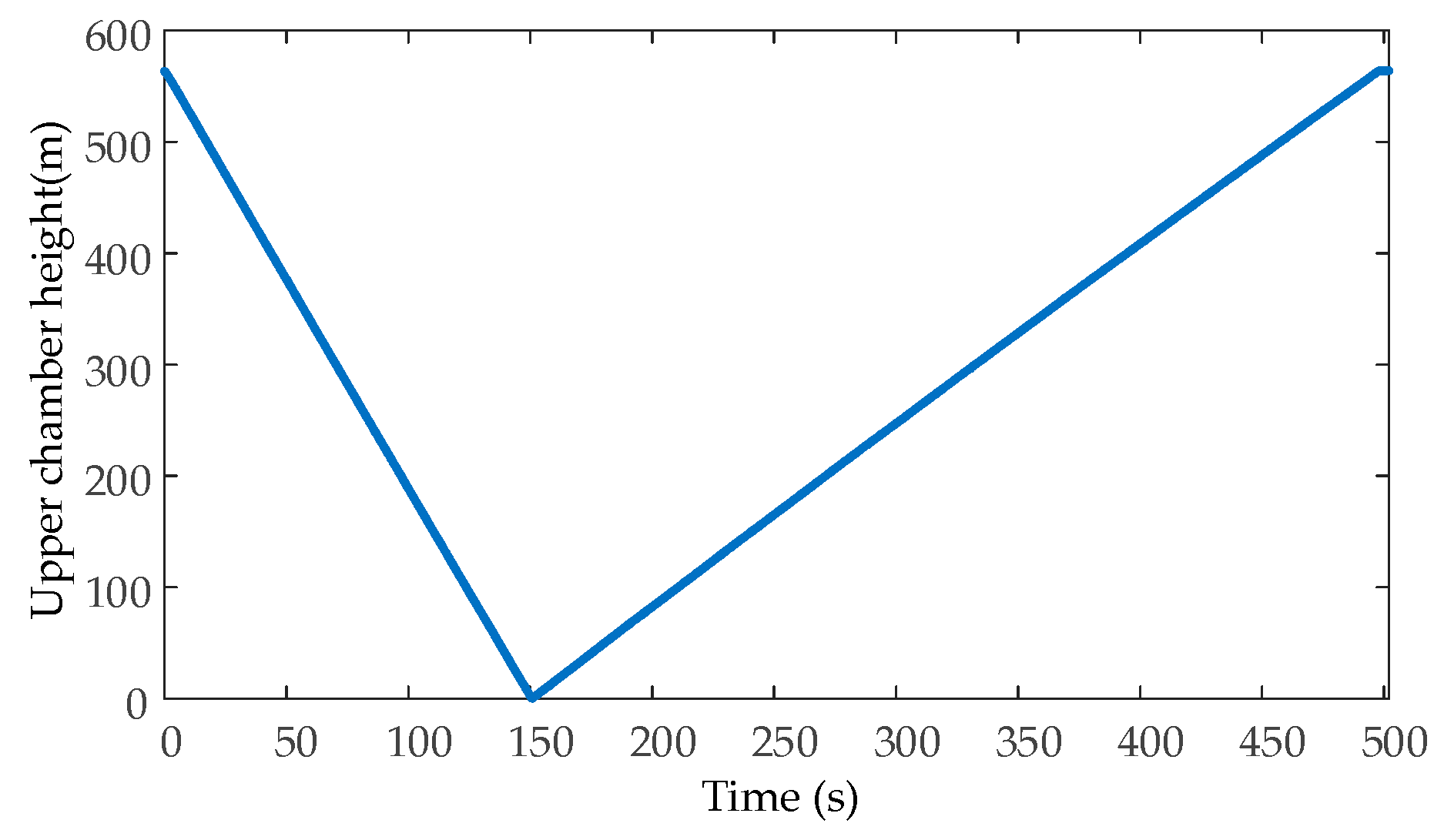
Figure 10 shows the experimental curve of the upper chamber height. Initially, the piston is located at the bottom of the cylinder, corresponding to an upper chamber height of 563 mm. During charging conditions (0–151 s), the injected water pushes the piston upward at a constant speed, causing the height to decrease linearly from 563 mm to 0 mm. During discharging conditions (151–502 s), the piston descends under gravity, and the height returns linearly to 563 mm, demonstrating stable reverse motion.
Figure 10.
Experimental curve of upper chamber height.
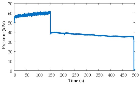
The experimental curve of pressure in the lower chamber is shown in Figure 11. During charging conditions, the lower chamber pressure rises from 50 kPa to 60 kPa as the piston compresses the trapped water. When switching to discharge, the pressure initially drops to 38 kPa and then gradually declines to 32.7 kPa as the piston descends and the chamber volume expands. As the piston approaches the bottom of the vertical cylinder, the pressure falls abruptly to 0 kPa. As indicated by Equation (6), the lower chamber pressure is inversely proportional to the upper chamber height.
Figure 11.
Experimental curve of pressure in lower chamber.
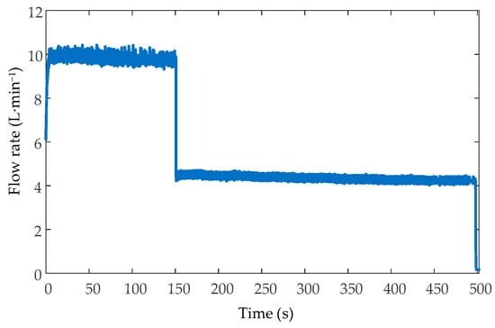
Figure 12 presents the experimental curve of the flow rate. During charging conditions, the flow rate is maintained at 10 L·min−1, whereas during discharging conditions, it drops to 4.3 L·min−1. During the charging condition, the pump actively pumps water from the acrylic water tank into the lower chamber of the vertical cylinder under pressure, generating a significant pressure differential; during the discharging condition, however, the pressure differential generated by the piston’s own weight is less than that produced by the pump. Thus, the flow rate under charging conditions is higher than that under discharging conditions.
Figure 12.
Experimental curve of flow.
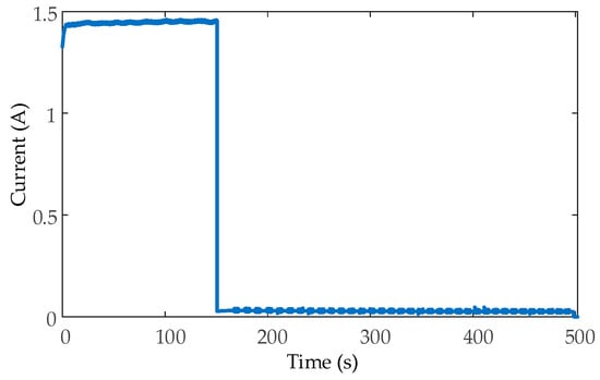
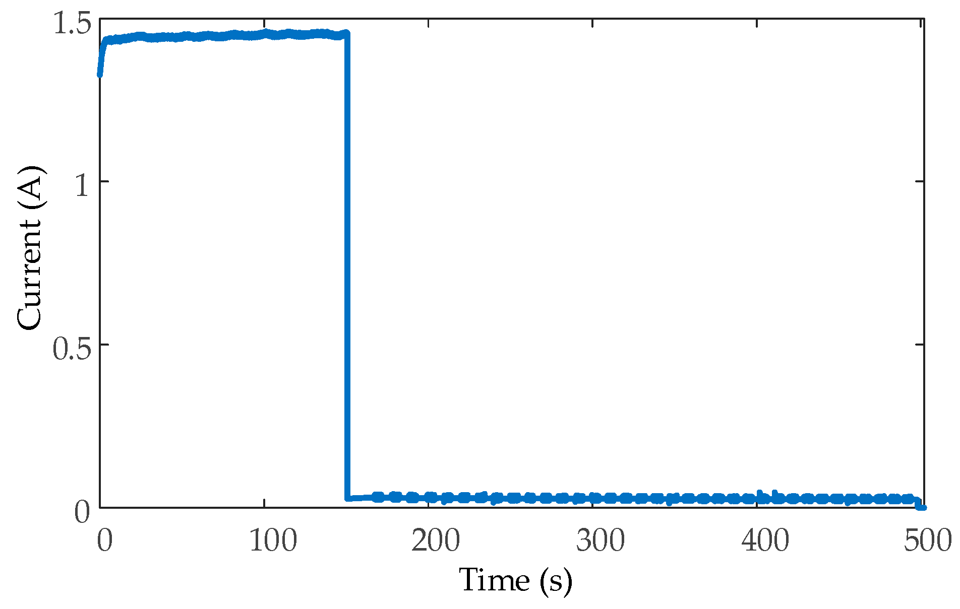
The experimental curve of current is shown in Figure 13. In the experimental system, the currents of the pump and the turbine are collected using different transmitters: the pump current is an AC signal measured by an AC current transmitter, while the turbine output current is a DC signal measured by a DC current transmitter. During charging conditions, the pump current is measured as 1.37 A. In discharging conditions, the turbine output current is recorded as 0.03 A. This large difference arises because the 380 W pump and the 5 W turbine operate far from their design water heads.
Figure 13.
Experimental curve of current.
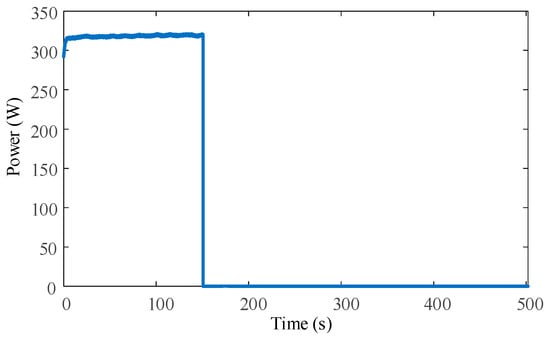
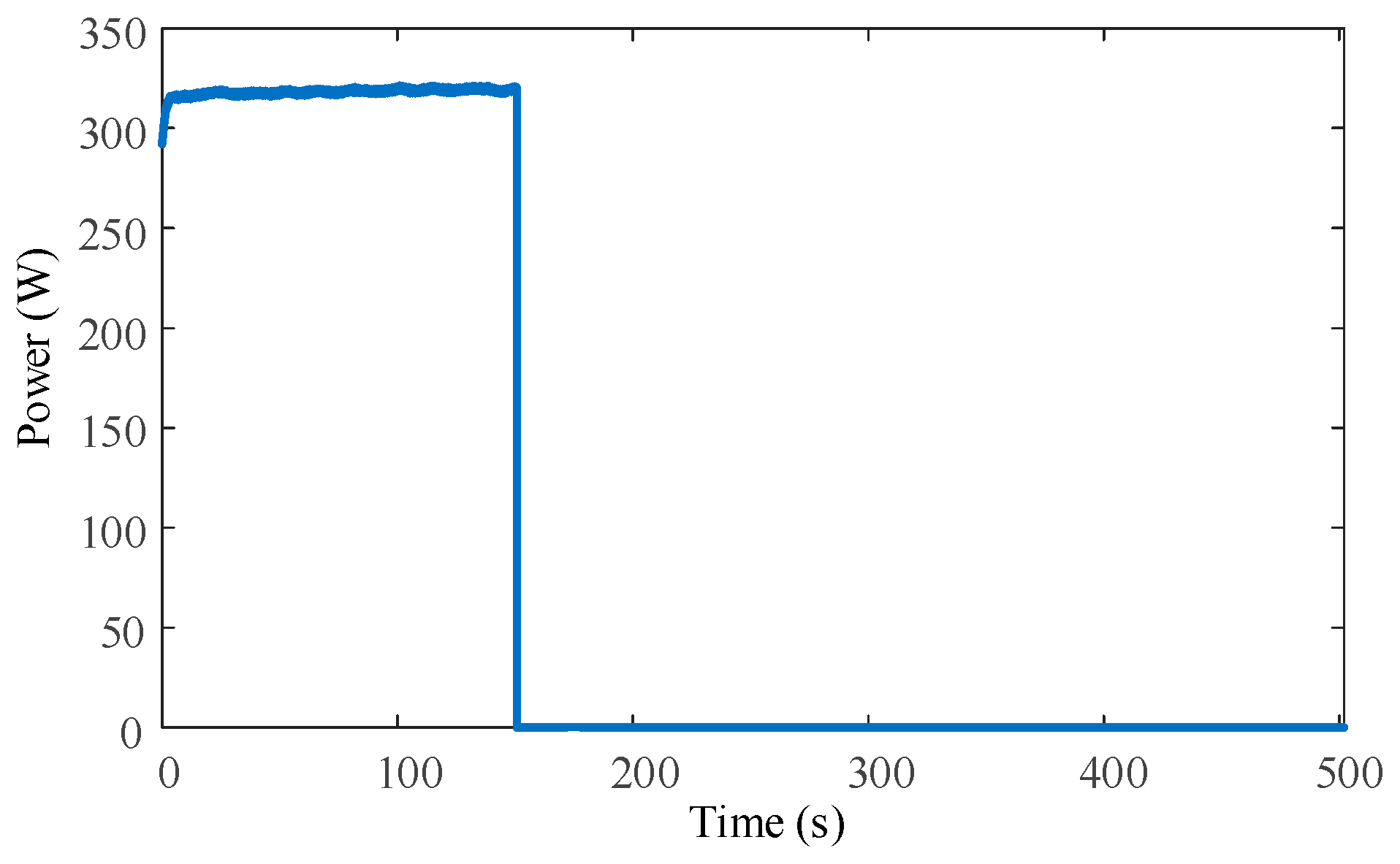
The experimental curve of power is shown in Figure 14. The charging power is 317 W, and the discharging power is 0.1 W. The corresponding charging and discharging times are 151 s and 351 s, respectively. The resulting charging–discharging efficiency of the system is relatively low. This diminished performance is likely attributable to the fact that the pump and turbine are not operating within their optimal efficiency zones, thereby impairing the energy conversion during charging and discharging conditions. The pump has a rated power of 380 W and a rated voltage of 220 V. Its optimum head is 35–40 m, yet the actual head is only 5–6 m. The turbine is rated at 5 W and 5 V, with an optimum head of 8–10 m, whereas the actual head is 3.2–3.8 m. It is evident that neither the pump nor the turbine is operating within their optimal ranges. To verify the feasibility of the piston gravity energy-storage system, and neglecting the energy losses of the pump and turbine, the input and output power can be derived indirectly from the lower chamber pressure and the flow rate, as calculated in Equation (15).
where Pexp is the experimental value of the charging/discharging power, pexp is the experimental value of the lower chamber pressure, and qexp is the experimental value of the flow rate.
Figure 14.
Experimental curve of power.
By recalculating the charging and discharging power with Equation (15), the charging power is 10 W and the discharging power is 2.8 W. The system’s charge–discharge efficiency is 65%. Energy losses are primarily attributable to the frictional resistance between the piston and the cylinder wall, along with the hydraulic losses in the penstock. This efficiency only reflects the friction at the piston seals and the hydraulic losses in the penstock. It does not represent the overall efficiency of the system. Rather, it indicates the level of charging–discharging efficiency that can be achieved by a piston gravity energy-storage system when a suitable, high-efficiency pump and turbine are selected.
5. Discussion
Challenges and issues encountered during the construction and commissioning of the piston gravity energy-storage experimental system are as follows:
- (1)
- The experimental system requires the selection of appropriately sized O-rings; if the O-ring diameter is too large, it will increase friction and impede the descent of the piston, whilst if the diameter is too small, it will fail to provide an effective seal. Within the 4 × 3 mm mounting slot, experimental verification has shown that a ‘smaller top, larger bottom’ dual-ring configuration is effective: a 220 × 3.5 mm seal is used at the top to guide the piston and prevent wobbling, whilst a 230 × 3.5 mm seal is used at the bottom to provide the sealing function. This minimizes friction whilst ensuring a secure seal.
- (2)
- Due to component availability constraints, a 380 W pump was paired with a 5 W turbine. The pump operated at a 5–6 m head (optimum: 35–40 m) and the turbine at 3.2–3.8 m (optimum: 8–10 m). This severe mismatch resulted in a direct electrical efficiency of only 0.7% and necessitated the indirect hydraulic power calculation method.
The experimental system has been used to verify the principles of the energy-storage system and to conduct a preliminary analysis of its dynamic characteristics. However, it must be acknowledged that the system still has the following limitations:
- (1)
- Only constant power operating conditions were tested, and the dynamic response under variable power conditions was not investigated.
- (2)
- The pump and turbine were unable to operate within their optimal efficiency ranges, resulting in a relatively low actual charge–discharge efficiency.
The trends in the key parameters of the experimental system are consistent with those of the simulation system, with a theoretical charge–discharge efficiency of 65%, demonstrating that the proposed model is suitable for preliminary application in engineering practice. To enhance the system’s dynamic performance, advanced control methods, such as feedforward control and model predictive control, may be considered.
6. Conclusions
A mathematical and simulation model is developed for a novel piston gravity energy-storage system, and its dynamic response during discharge is analyzed. To further investigate the dynamic response characteristics of the system, an experimental system is constructed. The research findings are summarized as follows:
- (1)
- Based on an analysis of the structure and operating principle of the piston gravity energy-storage system, the system is decomposed into four modules, with separate models developed for the piston motion, the vertical cylinder chamber pressure, the hydraulic actuator, and the hydraulic turbine power. The proposed model effectively captures the dynamic behavior of the system and simulates the transient responses of chamber pressure, flow rate, and discharging power.
- (2)
- An experimental system for piston gravity energy storage is constructed, employing a digital controller and sensors to realize closed-loop control and real-time dynamic data acquisition during charging and discharging conditions. Under constant-power operations, the height of the upper chamber varies linearly, the lower chamber pressure is inversely proportional to the upper chamber height, and both the flow rate and the charging/discharging power remain stable. Neglecting energy losses of the pump and the hydraulic turbine, the charge–discharge efficiency of the experimental system attains 65%, validating the feasibility of the experimental system design.
Research on the performance of piston gravity energy-storage systems remains incomplete, and further investigation is required to clarify how various design parameters influence system performance. In the modeling of the piston gravity energy-storage system, the following aspects could be further considered: the inertial delay during the initial stage of piston movement, the dependence of system responsiveness on pressure levels, the “start-stop” dynamics during directional changes, and the influence of the working fluid’s viscosity. The charge–discharge efficiency of the experimental platform for the experimental system is relatively low. Potential improvements may be achieved by optimizing the hydraulic circuit configuration and the selection of pumps and turbines.
Author Contributions
Conceptualization, Y.W. and Z.W.; methodology, Z.W.; software, Z.W.; validation, Z.W. and P.W.; formal analysis, Z.W.; investigation, Z.W. and P.W.; resources, Y.W. and Z.W.; data curation, Z.W. and P.W.; writing—original draft preparation, Z.W.; writing—review and editing, Y.W.; visualization, Z.W.; supervision, Y.W.; project administration, Y.S.; funding acquisition, Y.S. All authors have read and agreed to the published version of the manuscript.
Funding
This research was funded by the National Natural Science Foundation of China (52507123).
Data Availability Statement
The original contributions presented in this study are included in the article. Further inquiries can be directed to the corresponding author.
Conflicts of Interest
The authors declare no conflicts of interest.
References
- Wang, F.; Xue, Y. A review of the development of the energy storage industry in China: Challenges and opportunities. Energies 2025, 18, 1512. [Google Scholar] [CrossRef] [Scilit]
- Guo, X.; Chen, X.; Chen, X.; Sherman, P.; Wen, J.; McElroy, M. Grid integration feasibility and investment planning of offshore wind power under carbon-neutral transition in China. Nat. Commun. 2023, 14, 2447. [Google Scholar] [CrossRef] [Scilit] [PubMed]
- Wang, R.; Zhang, L.; Shi, C.; Zhao, C. A review of gravity energy storage. Energies 2025, 18, 1812. [Google Scholar] [CrossRef] [Scilit]
- Xie, X.; Ma, N.; Liu, W.; Zhao, W.; Xu, P.; Li, H. Functions of energy storage in renewable energy dominated power systems: Review and prospect. Proc. CSEE 2023, 43, 158–169. [Google Scholar] [CrossRef]
- Ruoso, A.; Caetano, N.; Rocha, L. Storage gravitational energy for small scale industrial and residential applications. Inventions 2019, 4, 64. [Google Scholar] [CrossRef] [Scilit]
- Li, F.; Xie, J.; Fan, Y.; Qiu, J. Potential of different forms of gravity energy storage. Sustain. Energy Technol. Assess. 2024, 64, 103728. [Google Scholar] [CrossRef] [Scilit]
- Kavoosi, A.; Hagh, M.T. Solid gravity energy storage: Pioneering energy storage solution—A review. J. Energy Storage 2025, 113, 115691. [Google Scholar] [CrossRef] [Scilit]
- Xiao, B.; Xiao, K.; Li, J.; Xiao, C.; Cao, S.; Liu, Z. Flexible electrochemical energy storage devices and related applications: Recent progress and challenges. Chem. Sci. 2024, 15, 11229–11266. [Google Scholar] [CrossRef] [Scilit] [PubMed]
- Zhou, Y.; Ning, Z.; Huang, K.; Guo, S.; Xu, C.; Chang, F. Sustainable energy integration: Enhancing the complementary operation of pumped-storage power and hydropower systems. Renew. Sustain. Energy Rev. 2025, 210, 115175. [Google Scholar] [CrossRef] [Scilit]
- Zhang, L.; Feng, G.; Huang, K.; Bi, Y.; Chang, S.; Li, A. Design and optimization for photovoltaic heat pump system integrating thermal energy storage and battery energy storage. Energy Build. 2025, 329, 115277. [Google Scholar] [CrossRef] [Scilit]
- Jankowski, M.; Pałac, A.; Sornek, K.; Goryl, W.; Żołądek, M.; Homa, M.; Filipowicz, M. Status and development perspectives of the compressed air energy storage (CAES) technologies—A literature review. Energies 2024, 17, 2064. [Google Scholar] [CrossRef] [Scilit]
- Yu, H.; Yao, L.; Cheng, F.; Li, Y.; Zhai, W.; Wang, Q. Prospects and challenges of gravity energy storage applications in new type power system. Proc. CSEE 2024, 61, 7177–7192. [Google Scholar] [CrossRef]
- Berrada, A.; Loudiyi, K.; Zorkani, I. Dynamic modeling and design considerations for gravity energy storage. J. Clean. Prod. 2017, 159, 336–345. [Google Scholar] [CrossRef] [Scilit]
- Emrani, A.; Berrada, A. Structural behavior and flow characteristics assessment of gravity energy storage system: Modeling and experimental validation. J. Energy Storage 2023, 72, 108277. [Google Scholar] [CrossRef] [Scilit]
- Tan, J.; Wang, Y.; Xue, H. Modeling and performance analysis of piston gravity energy storage system. Energy Storage Sci. Technol. 2025, 14, 2383. [Google Scholar] [CrossRef]
- Emrani, A.; Berrada, A.; Ameur, A.; Bakhouya, M. Assessment of the round-trip efficiency of gravity energy storage system: Analytical and numerical analysis of energy loss mechanisms. J. Energy Storage 2022, 55, 105504. [Google Scholar] [CrossRef] [Scilit]
- Emrani, A.; Berrada, A.; Bakhouya, M. Modeling and performance evaluation of the dynamic behavior of gravity energy storage with a wire rope hoisting system. J. Energy Storage 2021, 33, 102154. [Google Scholar] [CrossRef] [Scilit]
- He, D.; Luo, N.; Shen, Y. Performance analysis and multi-objective optimization of a compressed air piston hydraulic gravity energy storage (CAPHGES) system. J. Energy Storage 2025, 124, 116872. [Google Scholar] [CrossRef] [Scilit]
- Taheri, B.; Jabari, F.; Foroud, A. A green cogeneration microgrid composed of water-source heat pumps, a gravity energy storage, and a bio-fueled gas turbine: Design and techno-economic optimization. Sustain. Cities Soc. 2023, 95, 104594. [Google Scholar] [CrossRef] [Scilit]
- Emrani, A.; Berrada, A.; Arechkik, A.; Bakhouya, M. Improved techno-economic optimization of an off-grid hybrid solar/wind/gravity energy storage system based on performance indicators. J. Energy Storage 2022, 49, 104163. [Google Scholar] [CrossRef] [Scilit]
- Wang, Z.; Yu, X.; Dong, L.; Gao, T.; Hao, Z.; Gao, J.; Zhu, Y.; Li, Z.; Wang, B.; Mou, X.; et al. Key parameters design of chain-rail based slope gravity energy storage system for optimal efficiency. IEEE Trans. Ind. Appl. 2025, 62, 1349–1358. [Google Scholar] [CrossRef] [Scilit]
- Wang, Z.; Wu, G.; Fang, S.; Gao, T.; Li, C.; Eldeeb, H.H.; Huang, Y.; Xu, G.; Zhao, H. Mass-block-dragging-based starting method for synchronous generator/motor of gravity energy storage system. IEEE Trans. Ind. Appl. 2026. [Google Scholar] [CrossRef] [Scilit]
- Wang, Q.; Li, Y.; Zhang, Q.; Wang, D.; Wu, G.; Wang, Z.; Zhao, H. Energy efficiency analysis model and experimental verification of vertical gravity energy storage system based on belt drive. Energy Storage Sci. Technol. 2025, 14, 1141. [Google Scholar] [CrossRef]
- Gao, T.; Wang, Z.; Fang, S.; Zhang, Y.; Zhang, L.; Huang, Y.; Zhao, H. Energy efficiency analysis model and experimental verification of gravity energy storage system with gear box and chain transmission mechanisms. Energy Storage Sci. Technol. 2025, 14, 688. [Google Scholar] [CrossRef]
- Shen, Y. Performance Analysis and Optimization Design of Piston Gravity Energy Storage System Containing Compressed Air. Master’s Thesis, Xi’an University of Technology, Shanxi, China, 2024. [Google Scholar] [CrossRef]
- Wang, J.; Gong, G.; Yang, H. Research and online measurement of bulk modulus of hydraulic oil. J. Mech. Eng. 2009, 45, 120–125. [Google Scholar] [CrossRef] [Scilit]
- Feng, C.; Liu, C.; Wu, C.; Zheng, Y. Innovative adaptive fuzzy control strategy for pumped storage units under variable operating conditions. Power Grid Technol. 2024, 48, 2815–2822. [Google Scholar] [CrossRef]
- Berrada, A.; Loudiyi, K.; Garde, R. Dynamic modeling of gravity energy storage coupled with a PV energy plant. Energy 2017, 134, 323–335. [Google Scholar] [CrossRef] [Scilit]

Disclaimer/Publisher’s Note: The statements, opinions and data contained in all publications are solely those of the individual author(s) and contributor(s) and not of MDPI and/or the editor(s). MDPI and/or the editor(s) disclaim responsibility for any injury to people or property resulting from any ideas, methods, instructions or products referred to in the content. |
© 2026 by the authors. Licensee MDPI, Basel, Switzerland. This article is an open access article distributed under the terms and conditions of the Creative Commons Attribution (CC BY) license.