Article

Design and Experimental Validation of a High-Current Marx Pulse Generator with Coordinated Voltage Balancing and Current Sharing Based on Series–Parallel IGBTs


1
State Key Laboratory of Power Transmission Equipment & System Security and New Technology, School of Electrical Engineering, Chongqing University, Chongqing 400044, China
2
Datong Power Supply Company, State Grid Shanxi Electric Power Company, Datong 037008, China
*
Author to whom correspondence should be addressed.
Energies 2026, 19(11), 2546; https://doi.org/10.3390/en19112546
Submission received: 2 April 2026 / Revised: 11 May 2026 / Accepted: 13 May 2026 / Published: 25 May 2026
(This article belongs to the Section F6: High Voltage)

Abstract

Pulsed power systems require compact high-voltage pulse generators with high current capability, where series–parallel configurations of semiconductor switches are inevitable. However, voltage imbalance in series devices and current mismatch in parallel branches significantly degrade system reliability under high-current pulsed conditions. In this work, a high-current solid-state Marx pulse generator based on a series–parallel IGBT configuration is proposed with a coordinated voltage balancing and current sharing strategy. A passive RC snubber is employed to suppress dynamic voltage imbalance, while a coupled inductor is introduced to mitigate transient and steady-state current mismatch. Simulation and experimental results demonstrate that the prototype achieves a peak output of 5 kV and 1000 A with adjustable pulse widths of 2–10 μs. The current imbalance degree is reduced from 45.8% to 3.1%, indicating significantly improved current sharing performance. The proposed method provides an effective and scalable solution for high-current pulsed power applications.

1. Introduction

Pulsed power technology has expanded rapidly from military defense into civilian, industrial, and biomedical fields, providing essential technical support for applications ranging from electromagnetic weapons to tumor ablation and online monitoring of power equipment [1,2,3,4,5,6,7,8].
As pulsed power devices trend toward miniaturization and higher energy density, the severe degradation and electrical treeing of organic insulation materials under pulsed electric fields have become critical issues [9,10,11]. Therefore, developing a highly reliable high-voltage pulse source is essential for investigating these insulation breakdown mechanisms.
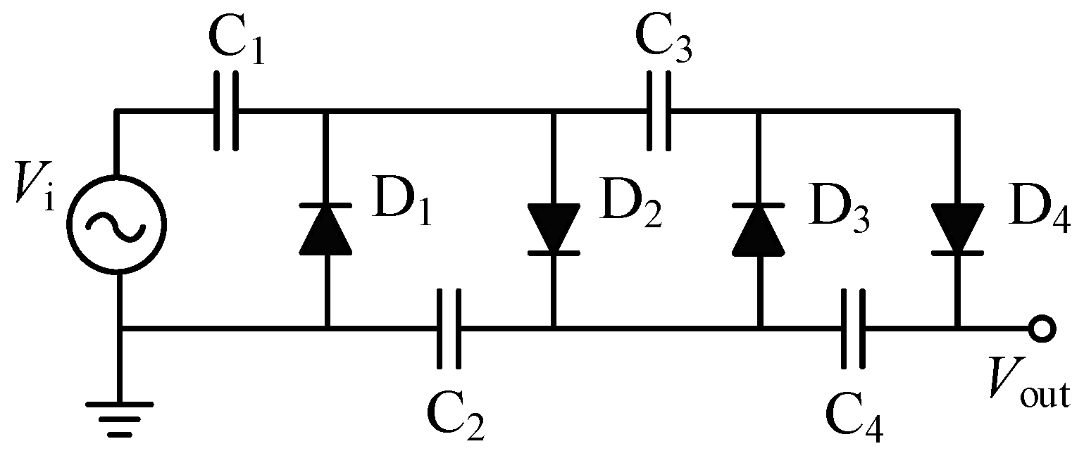
With the advancement of power electronics, solid-state switches—particularly Metal–Oxide-Semiconductor Field-Effect Transistors (MOSFETs) [12] and Insulated Gate Bipolar Transistors (IGBTs) [13]—have replaced traditional gas switches. Among various topologies [14,15,16,17,18,19,20,21,22], the Marx circuit is widely favored for its simple structure, modularity, and lack of impedance matching requirements. To achieve compactness and cost-effectiveness, researchers have proposed innovations such as Cockcroft–Walton voltage multiplier-powered Marx circuits [23], as shown in Figure 1.
Additionally, Marx circuit topologies based on hybrid inductor–capacitor energy storage have been proposed to prevent the entire circuit from burning out during a fault, significantly improving system reliability [24]. To further enhance the reliability, compactness, and flexibility of solid-state Marx generators, recent advancements have introduced several novel designs. These include modular SiC-MOSFET-based generators for biomedical applications [25], compact PFN-Marx generators utilizing high-energy-density mica capacitors [26], inductive isolation-based solid boost-Marx generators [27], and topologies equipped with fast recovery diodes to prevent through-currents [28]. Composite sources, such as linear transformer driver (LTD) structures combined with full-bridge switches [29], have also been explored. Furthermore, Collins and Martins [30] developed an oil-immersed pulse transformer based on pancake windings to meet the peak pulse power demands of solid-state klystron loads.
However, these composite structures often face limitations such as large volume, heavy weight, or complex synchronization. More importantly, many applications demand output currents of hundreds or thousands of amperes, which exceed the rated current of typical semiconductor switches, necessitating parallel configurations. Concurrently, series connections are required to reduce the number of stages and miniaturize the generator. However, most existing studies still treat voltage balancing and current sharing as independent design problems, while their coupled interaction under high-current pulsed conditions remains insufficiently investigated.
For high-current pulsed applications, series and parallel connection of semiconductor switches are often simultaneously required, which introduces coupled voltage-sharing and current-sharing challenges. In practical operation, voltage imbalance in series-connected devices and current mismatch in parallel branches are not completely independent phenomena, but may interact through parasitic coupling, switching transients, and uneven current stress distribution. This coupling effect can significantly influence switching reliability, current asymmetry, and the overall operational stability of the pulse generator. Therefore, developing an integrated coordinated balancing strategy is of considerable engineering importance for compact high-power solid-state Marx generators.
To develop a pulse generator with a large current capacity and a compact volume, this paper proposes a solid-state Marx pulse generator based on a series–parallel IGBT configuration. Appropriate series voltage equalization and parallel current sharing methods are theoretically analyzed, selected, and experimentally verified, laying the technical foundation for a composite high-voltage pulse source. The main contributions of this work are summarized as follows:
(1) A coordinated approach is proposed to address both voltage imbalance and current mismatch in series–parallel IGBT configurations under high-current pulsed conditions;
(2) A compact solid-state Marx pulse generator with integrated voltage balancing and current sharing mechanisms is developed;
(3) Experimental validation demonstrates a peak output of 5 kV and 1000 A, with significantly improved current sharing performance.
These comprehensive experimental results validate the feasibility and reliability of the proposed circuit topology.
The remainder of this paper is organized as follows: Section 2 analyzes the topology of the series–parallel IGBT circuit and its voltage equalization and current sharing mechanisms. Section 3 details the circuit simulations. Section 4 presents the prototype development and experimental results. Finally, Section 5 draws the conclusions. This work is particularly relevant to modern energy systems, where compact and high-power pulsed sources are required in applications such as power equipment testing, pulsed electric field treatment, and advanced power electronics.

2. Topology and Analysis of Series–Parallel IGBT Circuit

2.1. Principles of IGBT Series Voltage Equalization

Voltage equalization in series-connected IGBTs is primarily categorized into static and dynamic sharing. During the off-state, series-connected IGBTs operate in the cutoff region and generate leakage currents. Theoretically, the leakage current flowing through each series device should be identical. In practice, however, inevitable manufacturing tolerances and inherent parameter variations among individual IGBTs lead to discrepancies in these leakage currents. This deviation consequently alters the equivalent off-state impedances of the individual devices, preventing the series-connected IGBTs from inherently achieving a uniform static voltage distribution.
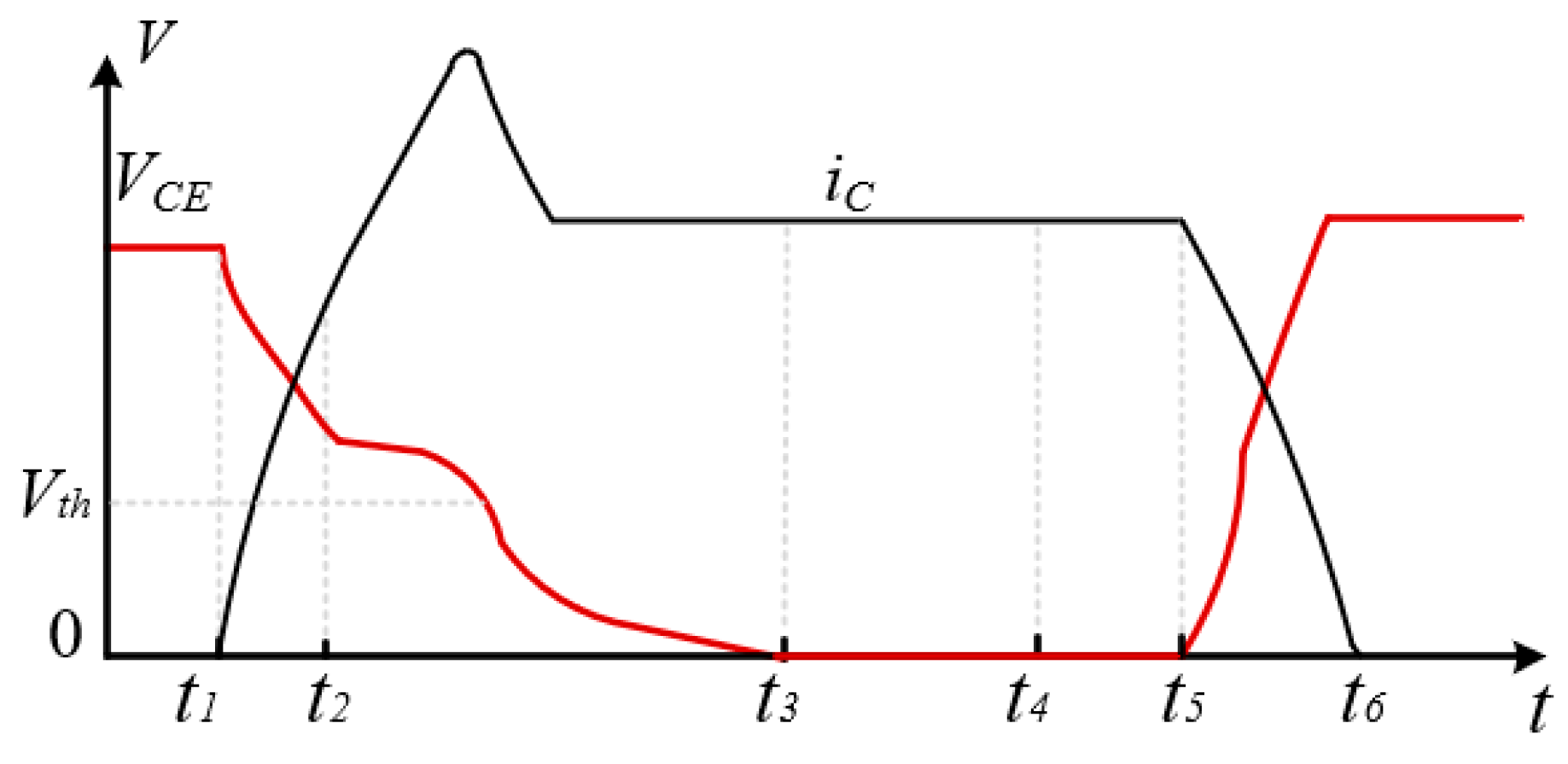
Dynamic voltage equalization is governed by the transient characteristics during the switching processes, encompassing the turn-on delay, current rise, and current fall phases, as illustrated in Figure 2.
During the turn-on delay phase, the gate drive circuit charges the equivalent input capacitance through the gate resistor, causing the gate voltage to rise exponentially as defined by Equation (1):
v G E t = ( V C C V E E ) 1 e t τ 1 + V E E
The corresponding time constant for this process is expressed in Equation (2):
τ 1 = r g C G E + C G C
which directly determines the turn-on delay time formulated as Equation (3):
t d ( o n ) = τ 1 ln 1 V t h V C C V E E
Once the gate voltage exceeds the conduction threshold, the collector current increases almost linearly, which can be approximated by Equation (4):
i C = k 2 ( V G E V t h )
This current variation induces a voltage drop across the stray inductance, causing the collector–emitter voltage to decrease rapidly until the device operates in the saturation region. Conversely, the turn-off transient involves the discharge of the gate capacitance, following a similar exponential decay formulated in Equation (5):
v G E ( t ) = ( V C C V E E ) 1 e t τ 2 + V E E
with its corresponding time constant given by Equation (6):
τ 2 = r g ( C G E + C G C )
When utilizing IGBTs as discharge switches in a Marx generator, dynamic voltage imbalance during the turn-off phase is of paramount concern. Because the steady-state conduction voltage drop is negligible compared to the extreme blocking voltage sustained in the off-state, any uneven voltage distribution during turn-off can subject individual IGBTs to destructive voltage spikes, potentially causing catastrophic overvoltage breakdown. This dynamic imbalance stems from three interconnected factors. First, asynchronous gate drive signals directly induce variations in the rate of change current and voltage among the series devices. Second, inconsistencies in inherent device parameters—such as varying gate-emitter and gate-collector capacitances—alter the equivalent impedances, leading to mismatched turn-on/turn-off delay times and divergent voltage gradients. Finally, asymmetrical parasitic capacitances within both the driving and power loops cause disparate gate and collector currents. These combined effects significantly compromise the dynamic voltage equalization of the series-connected IGBTs, necessitating appropriate voltage equalization strategies.

2.2. Principles of IGBT Parallel Current Sharing

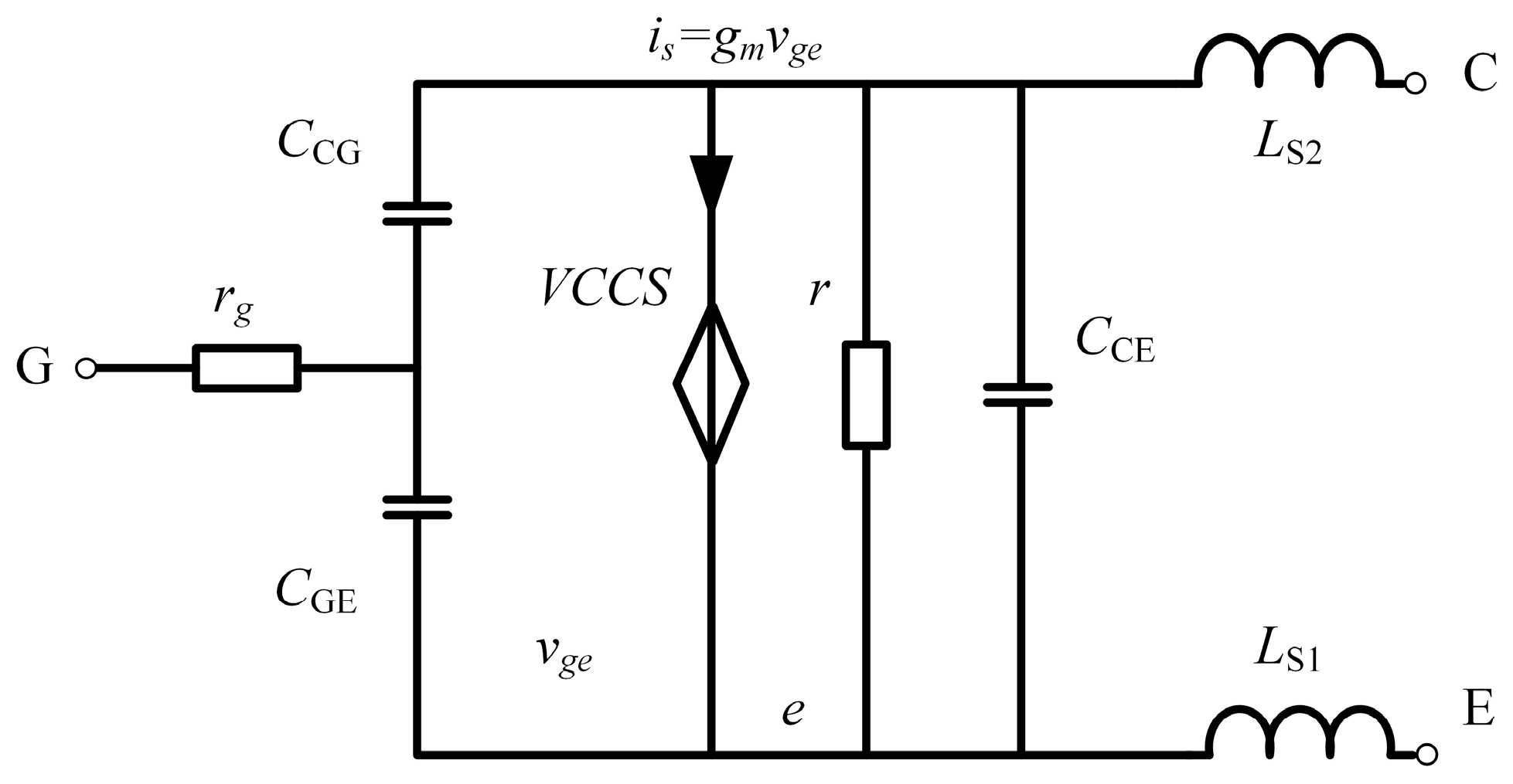
Based on its fundamental structure and operating principles, an IGBT can be equivalently modeled as a small-signal circuit comprising a voltage-controlled current source, an equivalent resistor, and various parasitic parameters, as illustrated in Figure 3.
In this model, CCG, CGE and CCE denote the collector–gate, gate–emitter, and collector–emitter parasitic capacitances, respectively; rg represents the internal gate resistance; and LS1 and LS2 correspond to the stray inductances in the current path. The diamond-shaped element denotes a voltage-controlled current source, representing the transconductance behavior of the IGBT. During the stable conduction phase, the static current distribution among parallel IGBTs is primarily governed by discrepancies in the equivalent on-state resistance, gate voltage, and transconductance coefficient of each branch. Therefore, to mitigate static current imbalance, it is essential to utilize IGBT modules from the same manufacturer and production batch, while ensuring maximum consistency in the applied gate driving voltages across all parallel devices.
Dynamic current sharing, conversely, is determined by the transient characteristics during the switching intervals. Variations in inherent device parameters—such as the gate resistance, equivalent input capacitance, and conduction threshold voltage—directly impact the synchronization of the switching initiation instants. These discrepancies cause the parallel devices to turn on or turn off at slightly different times, leading to severe transient current imbalances. If no specific current sharing mechanisms are implemented, the parallel IGBTs must be significantly derated to prevent individual devices from exceeding their maximum safe operating limits. However, this conservative approach inherently reduces the utilization efficiency of the solid-state switches and escalates the overall hardware cost, underscoring the necessity for effective current sharing strategies in high-current pulsed power applications.

2.3. Selection of Voltage Equalization and Current Sharing Methods

The load for the proposed Marx pulse generator is a high-ratio pulse transformer, which inherently acts as a low-impedance load. Although the operational frequency is relatively low, the required pulse current can reach hundreds to thousands of amperes. Consequently, IGBT modules are selected as the primary discharge switches over MOSFETs or discrete IGBTs due to their superior current-carrying capabilities. To achieve a compact and cost-effective pulse generator, these modules must be configured in a series–parallel array, which necessitates robust and reliable voltage equalization and current sharing strategies to ensure stable operation.
Several voltage-equalization methods have been reported for series-connected semiconductor switches, including passive resistor balancing, active gate-control balancing, magnetic-coupling balancing, and passive RC snubber balancing networks. Passive resistor balancing is simple and effective for static voltage sharing; however, its capability in dynamic voltage equalization and transient overvoltage suppression is limited. Active gate-control balancing methods can provide rapid dynamic compensation and excellent equalization performance; however, they require additional sensing, control, and synchronization circuits, resulting in increased system complexity and reduced robustness in high-voltage pulsed applications. Magnetic-coupling balancing methods are effective in transient equalization, but their insulation coordination, magnetic integration, and structural implementation become challenging in compact multi-stage Marx generators. In contrast, passive RC snubber balancing provides both static and dynamic voltage equalization with a simple structure, high reliability, low implementation cost, and good engineering robustness. Considering the low operating frequency, high-current load condition, and compact structural requirements of the proposed Marx pulse generator, the passive RC snubber method was selected as the most suitable voltage equalization strategy in this work.
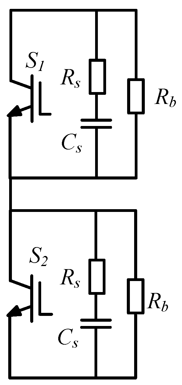
Based on the above comparison, a passive RC snubber balancing circuit was adopted in this work, as depicted in Figure 4.
In this configuration, a parallel static balancing resistor Rb is introduced to improve the static voltage-sharing performance of the series-connected IGBTs during the off-state. Although the resistor cannot guarantee perfectly equal voltage distribution independently of device tolerances, it reduces the influence of unequal off-state leakage currents by making the branch current mainly determined by the external resistor network rather than the intrinsic leakage-current variation in individual devices. Therefore, when Rb is properly selected so that the resistor current is significantly larger than the leakage-current mismatch, the static voltage distribution approaches uniform sharing. For dynamic equalization, a snubber capacitor Cs and a snubber resistor Rs are connected in series and placed in parallel with the collector and emitter. During the turn-off transient, if an unbalanced voltage spike occurs, the rising collector–emitter voltage charges Cs through Rs, thereby suppressing the voltage overshoot and preventing device breakdown. Conversely, during turn-on, Cs restricts abrupt voltage changes and subsequently discharges its stored energy through Rs. Although this passive network introduces minor supplementary power losses, its exceptional reliability, minimal driving circuit requirements, and cost-effectiveness make it highly suitable for low-frequency Marx generator applications.
Several current-sharing approaches have been reported for parallel-connected semiconductor switches, including emitter resistors, active current-balancing control, and magnetic-coupling current-sharing methods. Emitter resistors provide a simple balancing mechanism, but introduce additional conduction losses and reduce system efficiency under high-current operating conditions. Active current-balancing methods can achieve accurate current regulation, but require additional sensing circuits and closed-loop control strategies, which increase implementation complexity and reduce robustness. In contrast, magnetic-coupling current-sharing methods provide self-adaptive balancing with fast transient response, low conduction loss, and high reliability. Therefore, considering the high-current operating condition and the compact structural requirements of the proposed Marx generator, the coupled-inductor current-sharing method was adopted in this work.
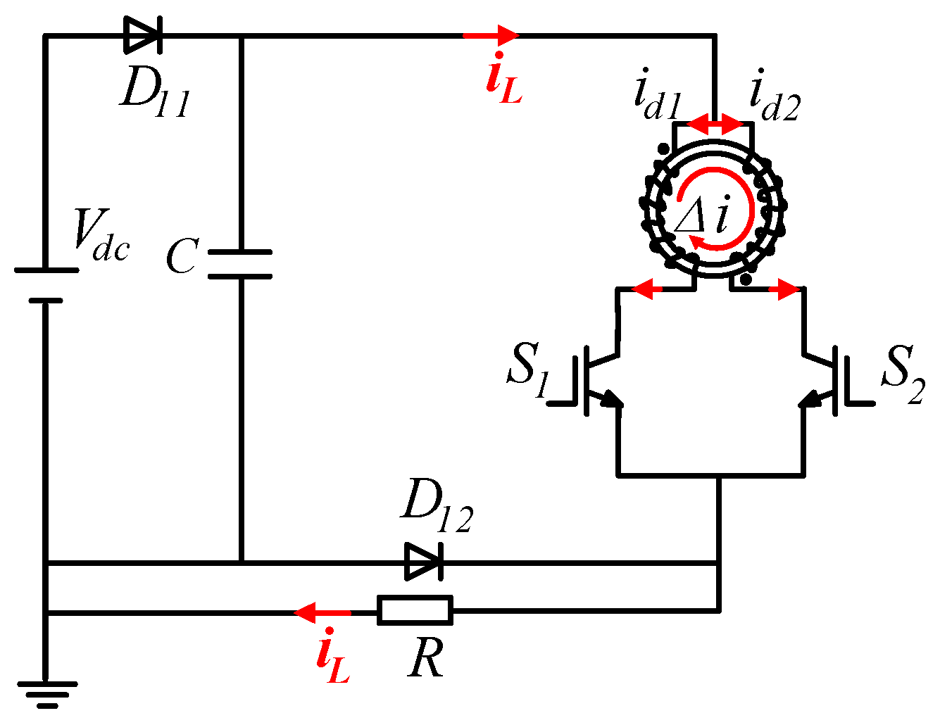
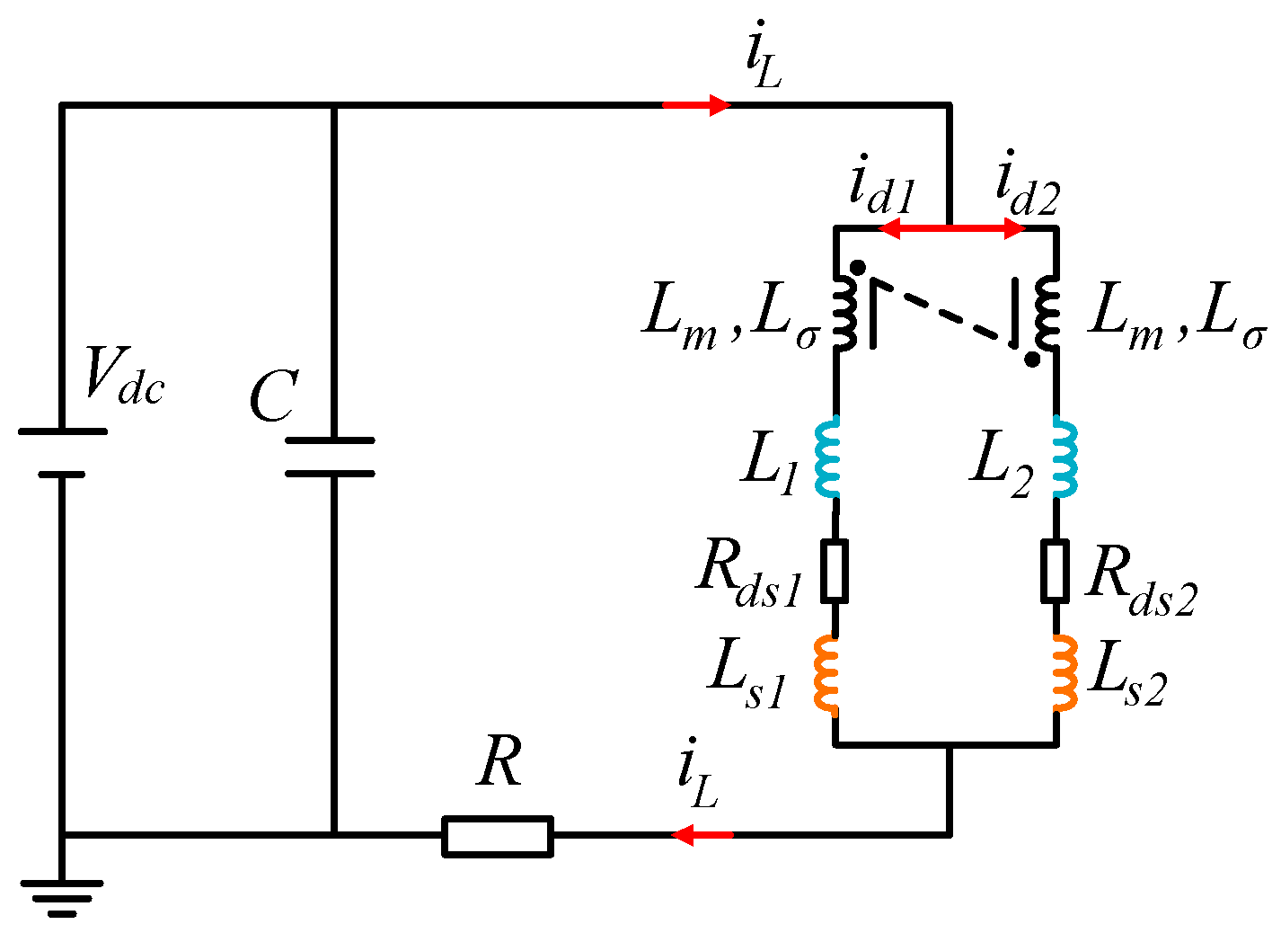
The implementation of this method in the Marx circuit and its equivalent model are illustrated in Figure 5 and Figure 6.
For the equivalent circuit in Figure 6, the two winding currents are denoted as i1 and i2. Since the two windings have equal turns and opposite magnetic polarities, the induced voltages:
v L 1 = L d i 1 / d t M d i 2 / d t
v L 2 = L d i 2 / d t M d i 1 / d t
where M = kL. Subtracting the two branch voltage equations gives:
r 1 i 1 r 2 i 2 + v C E 1 v C E 2 + L + M d i 1 i 2 / d t = 0
This expression indicates that the coupled inductor presents a high impedance to the differential current component. When one branch current becomes larger than the other, the net flux in the magnetic core produces an induced voltage that suppresses the current increase in the higher-current branch and promotes current recovery in the lower-current branch. Therefore, the current difference is reduced, and under symmetrical conditions the currents converge to i1 = i2 = Iload/2.
This technique effectively mitigates unbalanced current stresses during both the transient switching processes and the fully conducting state. When the parallel branches conduct, their respective currents flow through coupled coils that share a common magnetic core but feature identical turns and opposite winding directions. Under ideal symmetrical conditions, equal branch currents generate equal and opposite magnetic fluxes that entirely cancel each other out, exerting no influence on the circuit. In practice, however, inherent parametric discrepancies and loop asymmetries inevitably cause unequal branch currents, resulting in a net, non-zero magnetic flux within the core. According to Faraday’s law of electromagnetic induction, this net flux induces a counter-electromotive force in the coils that directly opposes the current deviation. This self-correcting mechanism continuously forces the unbalanced current toward zero, thereby ensuring highly effective parallel current sharing.

3. Circuit Simulation of the Series–Parallel IGBT Marx Pulse Generator

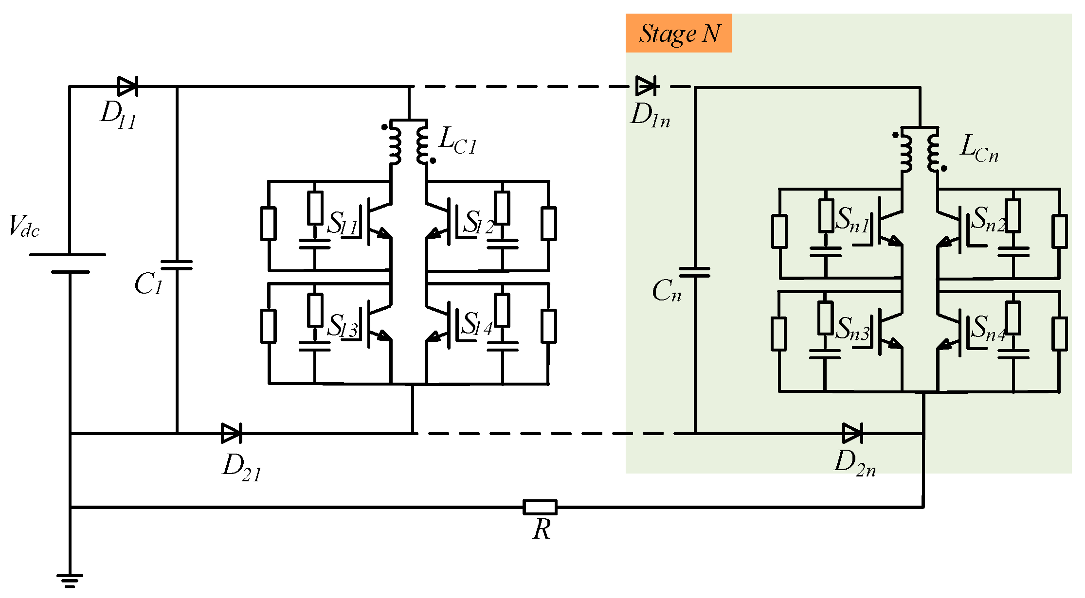
Based on the above analysis, combining the RC snubber circuit and the coupled-inductor current-sharing method, the IGBT series–parallel Marx circuit topology proposed in this paper is shown in Figure 7.
To verify the feasibility of the IGBT voltage and current balancing methods designed in the previous section in the Marx circuit, a circuit model was built using Cadence Pspice 17.4 simulation software for simulation verification.
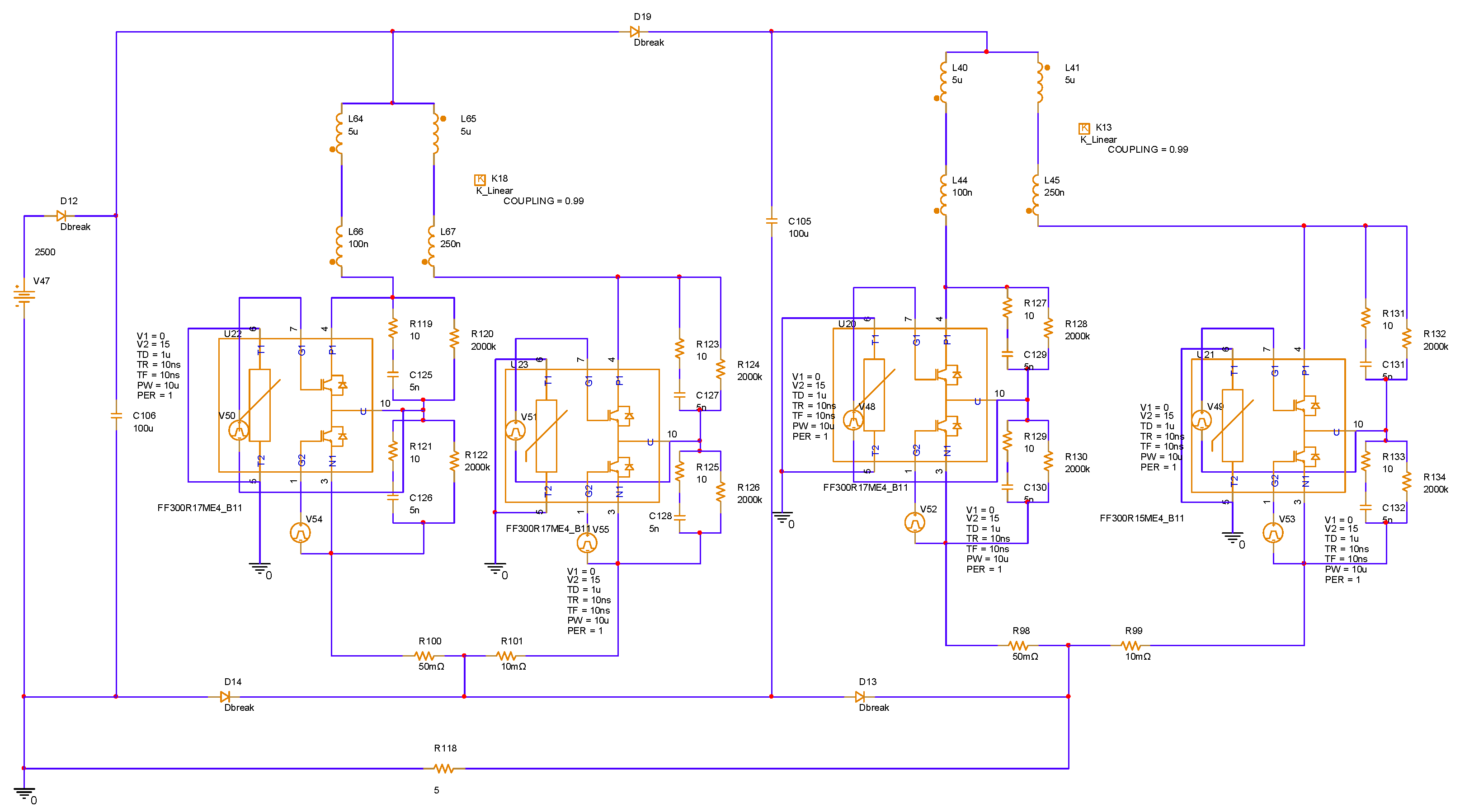
Based on the preceding component-level verifications, the complete series–parallel IGBT Marx circuit was constructed, seamlessly integrating the aforementioned RC snubber circuits and coupled inductors uniformly across all stages. To validate the overall feasibility and stability of the proposed topology, a comprehensive circuit model was established in PSpice. The detailed schematic of the simulated main circuit is illustrated in Figure 8.
The simulation is configured to target a maximum output voltage of 5 kV and a maximum output current of 1000 A, utilizing the FF300R17ME4 IGBT module. The specific circuit parameters applied in the simulation are detailed in Table 1.
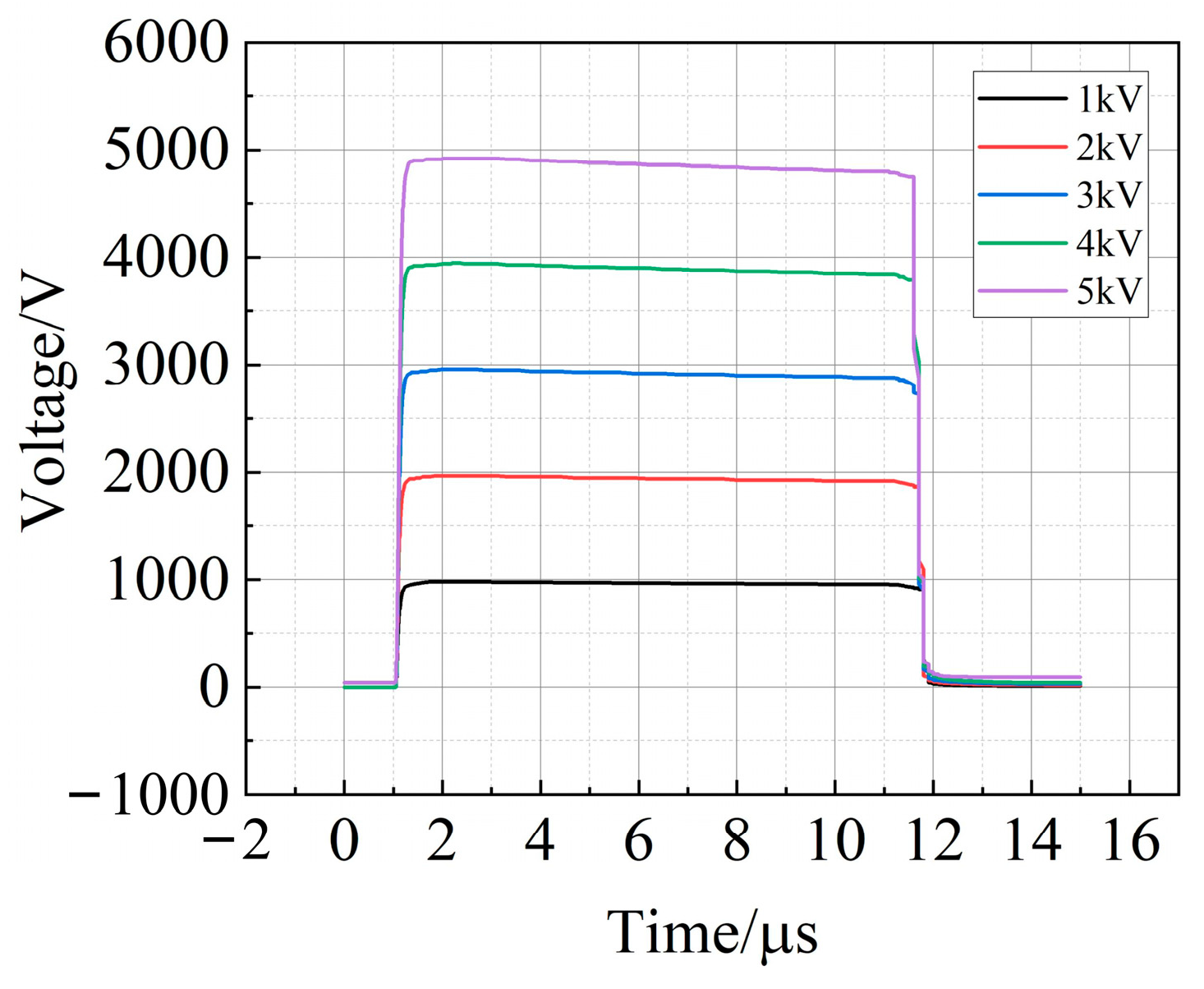
The series–parallel IGBT Marx pulse generator is designed to achieve a maximum output voltage of 5 kV and a maximum output current of 1000 A, with a flexibly adjustable pulse width ranging from 2 to 10 μs. The simulation utilizes the FF300R17ME4 IGBT model (Infineon Technologies AG, Germany), a two-stage pulse source configuration, and a 5 Ω load impedance. By setting the pulse width to 10 μs, the output voltage of the pulse generator can be effectively modulated by adjusting the magnitude of the DC input voltage, as illustrated in the step-up waveforms in Figure 9. The main purpose is to verify the output voltage amplitude regulation capability. The evaluation indicators include the peak value of the output voltage and the waveform consistency under different DC input voltages.
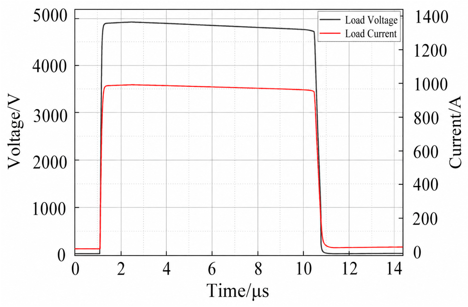
Furthermore, under the maximum rated design conditions, the generator successfully outputs a peak voltage of 5 kV and a corresponding peak current of 1000 A. The specific waveforms capturing this maximum amplitude output are presented in Figure 10. Figure 10 is intended to validate the maximum output capability of the proposed generator. The evaluation criteria include the maximum achievable output voltage, peak current, and pulse waveform stability under rated operating conditions.
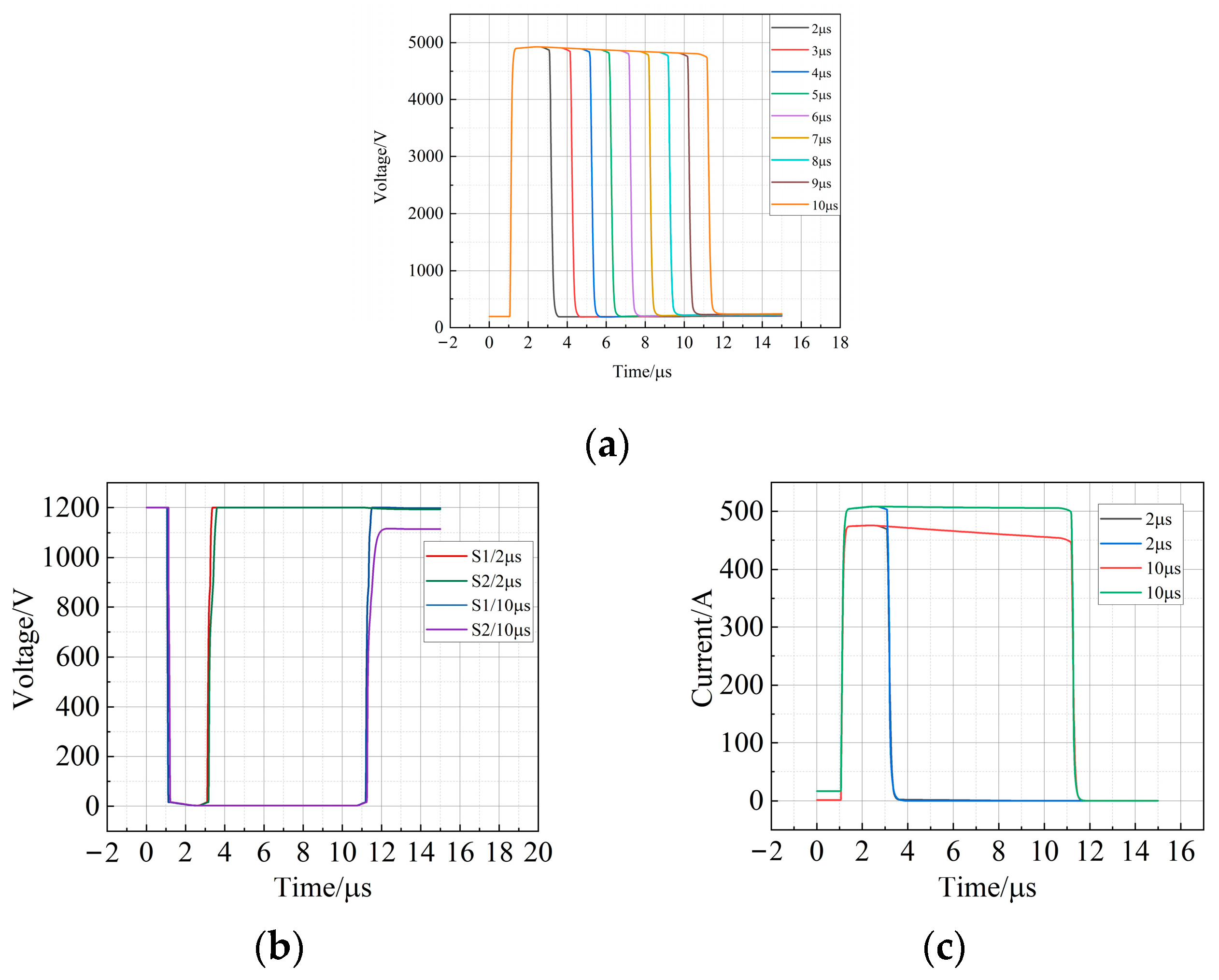
In addition to amplitude regulation, the pulse width of the generator can be flexibly adjusted from 2 to 10 μs by modifying the duration of the gate drive signals. The output voltage waveforms under various pulse widths, alongside the transient equalization and current sharing waveforms for the boundary conditions, are displayed in Figure 11. Figure 11 is used to evaluate the pulse width regulation flexibility, voltage equalization performance, and current sharing effectiveness of the proposed generator. The corresponding evaluation criteria include pulse width controllability, voltage consistency among series-connected IGBTs, and the current imbalance degree γ among parallel branches. Based on the above results, the proposed generator demonstrates good output adjustability and effective coordinated balancing performance.
To evaluate the severity of the current imbalance in the parallel IGBT branches, the current imbalance degree, γ is defined and expressed as follows:
γ = Δ i i a ν = Δ i I L / 2
The comprehensive simulation results indicate that the implemented RC snubber circuits and coupled inductors maintain exceptional balancing performance regardless of the varying pulse widths. Even under the extreme operational conditions of a 10 μs pulse width and a 1000 A load current, the current unbalance degree γ remains strictly controlled within 10%. Consequently, the simulation conclusively verifies the feasibility, flexibility, and robustness of the proposed series–parallel IGBT Marx pulse generator.

4. Prototype Development and Experimental Results

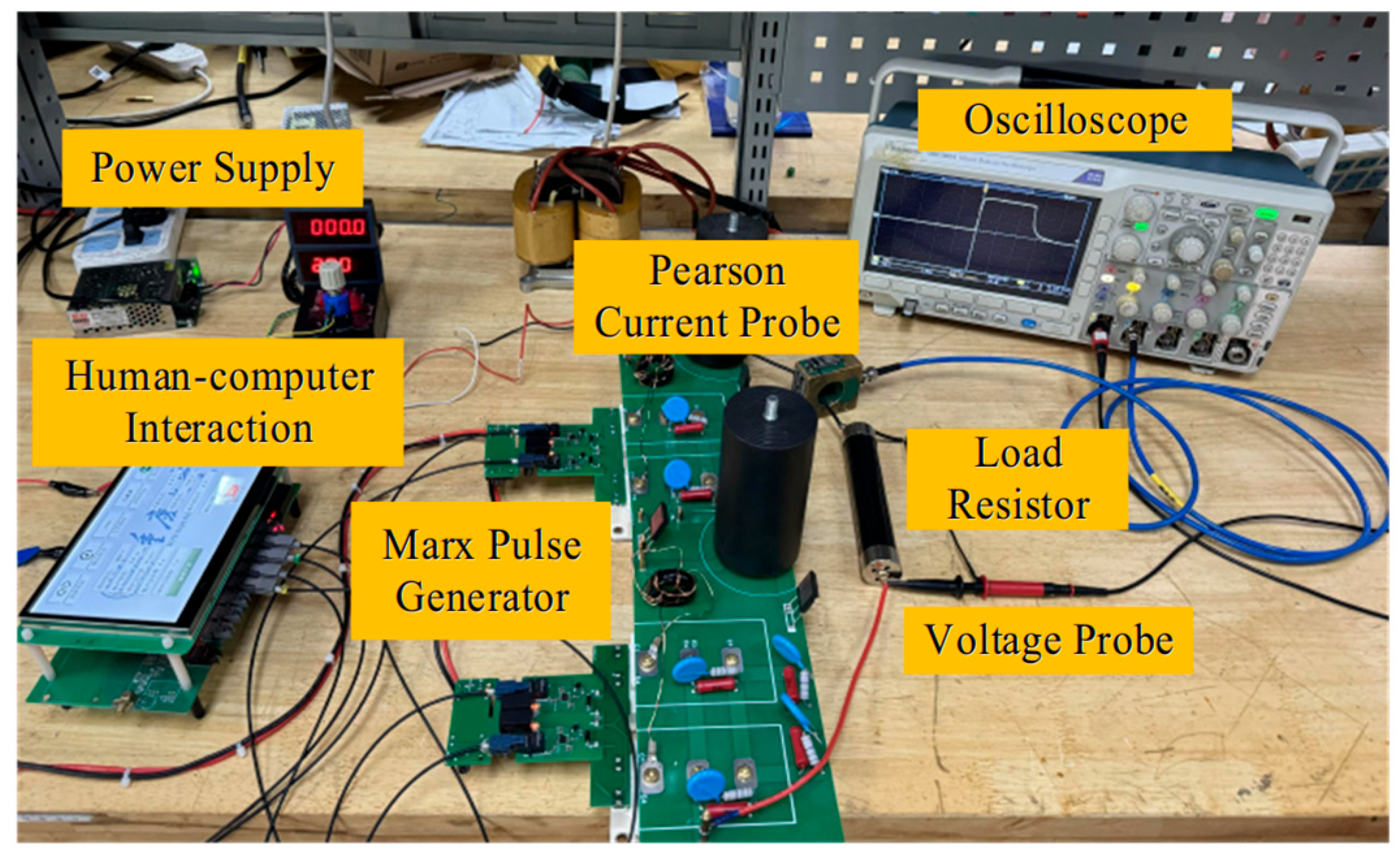
To practically validate the proposed series–parallel IGBT Marx pulse generator, a two-stage prototype was fabricated and tested. Based on the theoretical design and the stringent requirements of high-current, low-impedance loads, the key components were carefully selected. The main discharge switches utilize Infineon FF300R17ME4 IGBT (Infineon Technologies AG, Munich, Germany) modules, while IXYS DHH55-36N1F fast recovery diodes (IXYS Corporation, Milpitas, CA, USA) serve as the isolation diodes. The energy storage capacitors are rated at 3000 V with a capacitance of 100 μF. For the proposed protection networks, the RC snubber circuit comprises a 2 MΩ static balancing resistor, a 5 nF snubber capacitor, and a 10 Ω snubber resistor. The coupled inductor is constructed using an AlSiFe CS172125 magnetic core with an excitation inductance of 5.2 μH. With these optimally selected components, the experimental platform was systematically constructed to conduct comprehensive performance evaluations. The complete experimental setup is depicted in Figure 12.
During the tests, a DC power supply module was utilized to power the Marx circuit. Precise data acquisition was achieved using a Tektronix MDO 3024 oscilloscope (Tektronix Inc., Beaverton, OR, USA), Pearson 411 and 7790 current probes (Pearson Electronics Inc., Palo Alto, CA, USA), and a LeCroy PPE 6 kV high-voltage probe (LeCroy Corporation, Chestnut Ridge, NY, USA). The specific experimental parameters are detailed in Table 2.
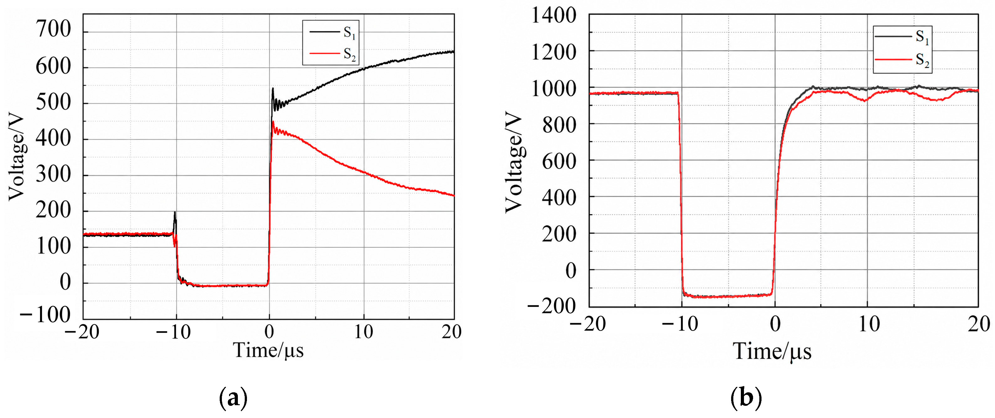
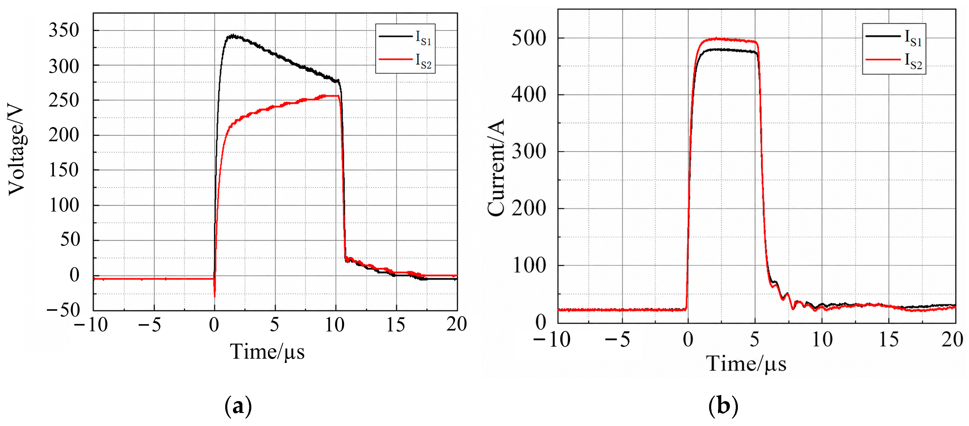
The effectiveness of the voltage equalization and current sharing strategies was initially verified under actual operating conditions. The measured collector–emitter voltages of the series-connected IGBTs, both without and with the RC snubber circuit, are presented in Figure 13.
The experimental waveforms clearly demonstrate that the RC snubber circuit effectively mitigates the dynamic and static voltage imbalances caused by inherent parameter discrepancies and asynchronous drive signals. Similarly, the performance of the coupled inductor is illustrated in Figure 14.
The integration of the coupled inductor drastically reduced the current unbalance degree γ from an initial 45.8% to a mere 3.1%, effectively suppressing the unbalanced currents during both the transient switching and steady-state conduction phases.
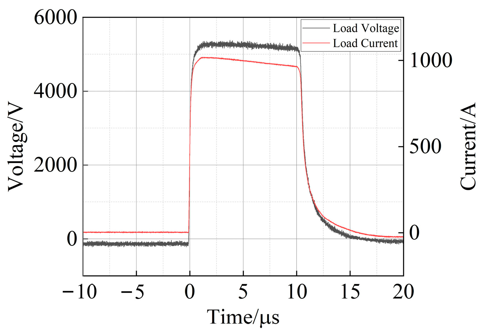
Following the component-level verification, the overall output capability of the series-parallel IGBT Marx pulse generator was tested utilizing a 5 Ω load resistor. The output voltage and current waveforms at the maximum designed amplitude are shown in Figure 15. Driven by the integrated equalization and current sharing measures, the prototype stably output a peak pulse voltage of 5 kV and a peak current of 1000 A, perfectly aligning with the simulation results.
Compared with conventional configurations without magnetic coupling, the proposed combined RC snubber and coupled inductor strategy demonstrates improved performance in both voltage equalization and current sharing.
Specifically, the current imbalance degree is significantly reduced from 45.8% to 3.1%, indicating that the proposed method effectively suppresses transient and steady-state current deviations, thereby enhancing the reliability and utilization efficiency of the series–parallel IGBT configuration.
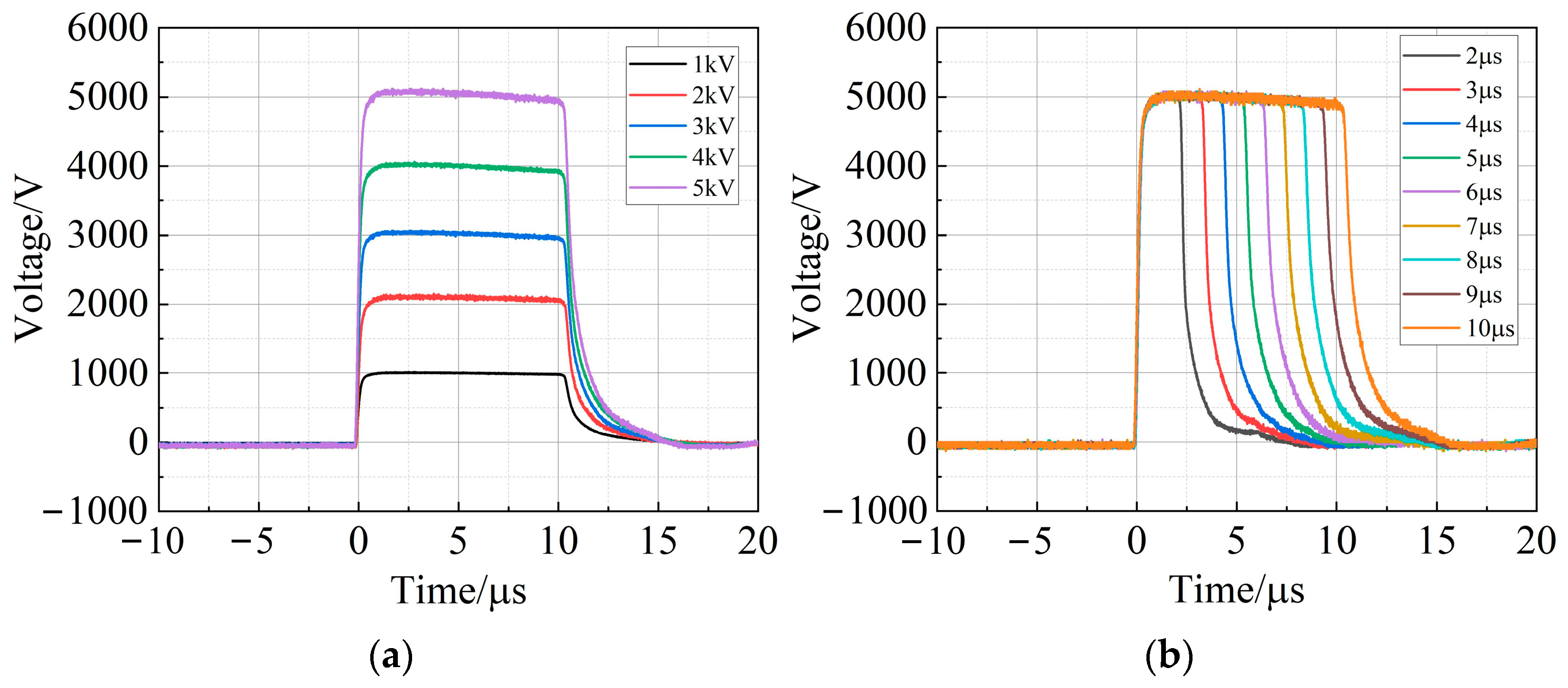
Furthermore, Figure 16 displays the pulse step-up capability at a maximum pulse width of 10 μs, alongside the flexible pulse width adjustment waveforms ranging from 2 to 10 μs at a constant 5 kV output. These comprehensive experimental results validate the feasibility and reliability of the proposed circuit topology, proving its suitability as a robust primary-side power source for composite high-voltage pulse generators.
The proposed coordinated balancing strategy demonstrates several engineering advantages for compact high-current pulsed power systems. First, the passive RC snubber effectively suppresses dynamic voltage overshoot without requiring additional active control, thereby simplifying gate-drive design and improving system robustness. Second, the coupled-inductor current-sharing method exhibits self-adaptive balancing behavior and significantly reduces branch-current asymmetry, improving semiconductor utilization and reducing overstress risk. Third, the coordinated design simultaneously addresses voltage imbalance and current mismatch, which is particularly beneficial in compact multi-stage Marx generators where parasitic coupling effects are significant. These features indicate strong application potential in high-power pulse modulators, pulsed electric field systems, and compact solid-state high-voltage pulse sources.
Compared with conventional independent designs, the proposed approach provides a more reliable solution for series–parallel IGBT configurations, especially in low-impedance load applications.
Nevertheless, the introduction of additional passive components may increase circuit complexity and power losses. Future work will focus on quantitative loss analysis of the passive balancing networks, optimization of coupled-inductor magnetic design, extension toward higher-voltage multi-stage topologies, and investigation of coordinated balancing performance under higher repetition-rate operating conditions.

5. Conclusions

To address the stringent high-current demands of low-impedance pulsed power applications, this paper successfully developed a compact solid-state Marx generator based on a series-parallel IGBT configuration. By implementing a passive RC snubber circuit and a coupled inductor, the inherent static and dynamic imbalances across the semiconductor switches were effectively mitigated. Theoretical analysis, PSpice simulations, and practical experiments consistently verified that these protection networks maintain exceptional voltage equalization and current-sharing performance without compromising the output waveform quality.
Compared with conventional independent voltage balancing and current sharing methods, the proposed coordinated strategy demonstrates enhanced performance under high-current pulsed conditions, particularly for low-impedance load applications. The experimental results show that the current imbalance degree is significantly reduced from 45.8% to 3.1%, while dynamic voltage overshoot is effectively suppressed. These improvements confirm that the proposed approach provides a reliable and scalable solution for high-power solid-state pulse generators.

Author Contributions

Conceptualization, C.Y.; methodology, C.Y., C.L. and S.D.; investigation, C.Y., Z.B., S.X. and L.Z.; data curation, S.X.; validation, C.L.; visualization, C.Y.; resources, Z.B. and L.Z.; writing—original draft preparation, C.Y.; writing—review and editing, S.D. and C.L.; funding acquisition, S.D.; supervision, S.D. All authors have read and agreed to the published version of the manuscript.

Funding

This research was supported by the National Natural Science Foundation of China (No. 52477229) and the Chongqing Natural Science Foundation (No. CSTB2024NSCQ-MSX0618). The APC was funded by the National Natural Science Foundation of China (No. 52477229).

Data Availability Statement

The data presented in this study are available on request from the corresponding author due to restrictions related to the large volume of experimental data and ongoing research work.

Conflicts of Interest

Author Zongqing Bo was employed by the Datong Power Supply Company, State Grid Shanxi Electric Power Company. The remaining authors declare that the research was conducted in the absence of any commercial or financial relationships that could be construed as a potential conflict of interest.

References

  1. Ma, W.; Lu, J. Thinking and study of electromagnetic launch technology. IEEE Trans. Plasma Sci. 2017, 45, 1071–1077. [Google Scholar] [CrossRef]
  2. Deng, J.; Shi, J.; Xie, W.; Zhang, L.W.; Feng, S.P.; Li, J.; Wang, M.; Xia, L.S.; Dai, Z.Y.; Li, H.T.; et al. Overview of pulsed power research at CAEP. IEEE Trans. Plasma Sci. 2015, 43, 2760–2765. [Google Scholar] [CrossRef]
  3. Azli, N.A.; Jambari, H.; Sultan, P.I.; Piah, M.A.M.; Ramlan, N.H. Implementation of cascaded H-bridge multilevel inverter for liquid food sterilization using pulsed electric field. In Proceedings of the 2014 IEEE Conference on Energy Conversion (CENCON), Johor Bahru, Malaysia, 13–14 October 2014; pp. 316–320. [Google Scholar]
  4. Qin, S.; Li, P.; Liang, G.; Liu, J.; Huang, S.; Meng, J. Pulsed Electric Field Treatment of Raw Milk and Its Effect on Protein-Free Amino Acids Transition. IEEE Trans. Plasma Sci. 2022, 50, 911–919. [Google Scholar] [CrossRef]
  5. Akiyama, H.; Sakugawa, T.; Namihira, T.; Takaki, K.; Minamitani, Y.; Shimomura, N. Industrial applications of pulsed power technology. IEEE Trans. Dielectr. Electr. Insul. 2007, 14, 1051–1064. [Google Scholar] [CrossRef]
  6. Mi, Y.; Xu, J.; Yao, C.; Li, C.; Liu, H. Electroporation modeling of a single cell exposed to high-frequency nanosecond pulse bursts. IEEE Trans. Dielectr. Electr. Insul. 2019, 26, 461–468. [Google Scholar] [CrossRef]
  7. Lv, Y.; Yao, C.; Rubinsky, B. A 2-D Cell Layer Study on Synergistic Combinations of High-Voltage and Low-Voltage Irreversible Electroporation Pulses. IEEE Trans. Biomed. Eng. 2020, 67, 957–965. [Google Scholar] [CrossRef] [PubMed]
  8. Zhao, Z.; Yao, C.; Hashemnia, N.; Islam, S. Determination of Nanosecond Pulse Parameters on Transfer Function Measurement for Power Transformer Winding Deformation. IEEE Trans. Dielectr. Electr. Insul. 2017, 23, 3761–3770. [Google Scholar] [CrossRef]
  9. Zhu, L.; Du, B.; Li, Z.; Su, J.; Jiang, J.; Kong, X. Electrical Tree Characteristics in Polypropylene Under Impulse Superimposed DC Voltage in LN2. IEEE Trans. Appl. Supercond. 2019, 29, 1–3. [Google Scholar] [CrossRef]
  10. Liu, Y.; Cao, X. Electrical tree initiation in XLPE cable insulation by application of DC and impulse voltage. IEEE Trans. Dielectr. Electr. Insul. 2013, 20, 1691–1698. [Google Scholar] [CrossRef]
  11. Mancinelli, P.; Cavallini, A.; Chalashkanov, N.; Dodd, S.J.; Dissado, L.A. Electrical treeing in silicone gel under square voltage: Frequency, rise time and crosslinking influence. In Proceedings of the IEEE Conference on Electrical Insulation and Dielectric Phenomena (CEIDP), Toronto, Italy, 16–19 October 2016; pp. 979–982. [Google Scholar]
  12. Han, L.; Liang, L.; Kang, Y.; Qiu, Y. A Review of SiC IGBT: Models, Fabrications, Characteristics, and Applications. IEEE Trans. Power Electron. 2021, 36, 2080–2093. [Google Scholar] [CrossRef]
  13. Zhou, X.; Zhang, Z.; Dong, S.; Yu, L.; Liu, J.; Qiao, X.; Yao, C. High Voltage Pulse Generator Based on a Novel Magnetic Isolated Drive Circuit. IEEE Trans. Power Electron. 2022, 37, 8157–8166. [Google Scholar] [CrossRef]
  14. Lassalle, F.; Morell, A.; Loyen, A.; Chanconie, T.; Roques, B.; Toury, M.; Vezinet, R. Development and Test of a 400-kV PFN Marx With Compactness and Rise Time Optimization. IEEE Trans. Plasma Sci. 2018, 46, 3313–3319. [Google Scholar] [CrossRef]
  15. Wang, L.; Liu, J. Solid-State Nanosecond Pulse Generator Using Photoconductive Semiconductor Switch and Helical Pulse Forming Line. IEEE Trans. Plasma Sci. 2018, 45, 3240–3245. [Google Scholar] [CrossRef]
  16. Mi, Y.; Bian, C.; Li, P.; Yao, C.; Li, C. A Modular Generator of Nanosecond Pulses with Adjustable Polarity and High Repetition Rate. IEEE Trans. Power Electron. 2018, 33, 10654–10662. [Google Scholar] [CrossRef]
  17. Mi, Y.; Bian, C.; Wan, J.; Xu, J.; Yao, C.; Li, C. A Modular Solid-state Nanosecond Pulsed Generator based on Blumlein-line and Transmission Line Transformer with Microstrip Line. IEEE Trans. Dielectr. Electr. Insul. 2017, 24, 2196–2202. [Google Scholar] [CrossRef]
  18. Kazemi, M.R.; Sugai, T.; Tokuchi, A.; Jiang, W. Study of Pulsed Atmospheric Discharge Using Solid-State LTD. IEEE Trans. Plasma Sci. 2017, 45, 2323–2327. [Google Scholar] [CrossRef]
  19. Shen, S.; Yan, J.; Wang, Y.; Sun, G.; Ding, W. Further Investigations on a Modified Avalanche Transistor-Based Marx Bank Circuit. IEEE Trans. Instrum. Meas. 2020, 69, 8506–8513. [Google Scholar] [CrossRef]
  20. Liu, Y.; Fan, R.; Zhang, X.; Tu, Z.; Zhang, J. Bipolar high voltage pulse generator without H-bridge based on cascade of positive and negative Marx generators. IEEE Trans. Dielectr. Electr. Insul. 2019, 26, 476–483. [Google Scholar] [CrossRef]
  21. Ren, X.; Sugai, T.; Tokuchi, A.; Jiang, W. Solid-State Marx Generator Circuit Based on Inductive Energy Storage. IEEE Trans. Plasma Sci. 2021, 49, 3377–3382. [Google Scholar] [CrossRef]
  22. Zeng, W.; Yu, L.; Dong, S.; Ma, J.; Wang, Y.; He, Y.; Wang, X.; Yao, C. A Novel High Frequency Bipolar Pulsed Power Generator for Biological Applications. IEEE Trans. Power Electron. 2020, 35, 12861–12870. [Google Scholar] [CrossRef]
  23. Aranganadin, K.; Zhang, Z.; Lin, Y.-C.; Wang, J.; Liu, Y.; Chen, H.; Li, X.; Zhao, M.; Sun, Q.; Huang, D.; et al. A Mini-Marx Generator Powered by a Cockcroft–Walton Voltage Multiplier. IEEE Trans. Plasma Sci. 2022, 50, 3393–3399. [Google Scholar] [CrossRef]
  24. Ren, X.; Sugai, T.; Tokuchi, A.; Jiang, W. Solid-State Marx Generator Using Hybrid Energy Storage. IEEE Trans. Plasma Sci. 2022, 50, 4905–4911. [Google Scholar] [CrossRef]
  25. Achour, Y.; Starzyński, J.; Rąbkowski, J. Modular Marx Generator Based on SiC-MOSFET Generating Adjustable Rectangular Pulses. Energies 2021, 14, 3492. [Google Scholar] [CrossRef]
  26. Zhang, H.; Shu, T.; Liu, S.; Zhang, Z.; Song, L.; Zhang, H. A Compact Modular 5 GW Pulse PFN-Marx Generator for Driving HPM Source. Electronics 2021, 10, 545. [Google Scholar] [CrossRef]
  27. Jin, Y.; Cheng, L. An Inductive Isolation-Based 10 kV Modular Solid Boost-Marx Pulse Generator. Electronics 2023, 12, 1586. [Google Scholar] [CrossRef]
  28. Shi, F.; Chen, P.; Jiang, S.; Zhuang, J.; Rao, J. A Solid-State Marx Generator with Prevention of through Current for Rectangular Pulses. Electronics 2024, 13, 101. [Google Scholar] [CrossRef]
  29. Wang, Y.; Xu, L.; Jiang, S.; Li, Z.; Rao, J. Solid-State Linear Transformer Driver Based on Full-Bridge Bricks. IEEE Trans. Plasma Sci. 2022, 50, 1269–1275. [Google Scholar] [CrossRef]
  30. Collins, M.; Martins, C.A. Evaluation of Feasibility of High-Power Long-Pulse Transformers Using Single-Layer and Pancake Winding Techniques. IEEE Trans. Plasma Sci. 2021, 49, 2217–2226. [Google Scholar] [CrossRef]
Figure 1. Voltage multiplier circuit schematic.
Energies 19 02546 g001
Figure 2. On-off process of IGBT.
Energies 19 02546 g002
Figure 3. Small signal circuit model of IGBT.
Energies 19 02546 g003
Figure 4. RC buffer circuit.
Energies 19 02546 g004
Figure 5. Marx circuit topology based on coupled inductor equalization.
Energies 19 02546 g005
Figure 6. Equivalent circuit model based on coupled inductor equalizing current.
Energies 19 02546 g006
Figure 7. IGBT Series–Parallel Marx circuit topology.
Energies 19 02546 g007
Figure 8. IGBT series–parallel Marx simulation circuit.
Energies 19 02546 g008
Figure 9. Pulse source boost waveform.
Energies 19 02546 g009
Figure 10. Maximum magnitude output waveform.
Energies 19 02546 g010
Figure 11. Output pulse width adjustment waveform. (a) Pulse source pulse width adjustment waveform. (b) Waveform of voltage equalization with different pulse widths. (c) Waveform of current sharing with different pulse widths.
Energies 19 02546 g011
Figure 12. Experimental test platform.
Energies 19 02546 g012
Figure 13. Voltage equalization performance of series-connected IGBTs with RC snubber (a) Without RC snubber. (b) With RC snubber.
Energies 19 02546 g013
Figure 14. Experimental results of coupled-inductor current sharing. (a) Without coupled inductance. (b) With coupled inductance.
Energies 19 02546 g014
Figure 15. Maximum magnitude output measured waveform.
Energies 19 02546 g015
Figure 16. Measured output waveform of Marx pulse source. (a) Waveform of different pulse voltage. (b) Waveform of different pulse width.
Energies 19 02546 g016
Table 1. Simulation circuit parameters.
ParameterValue
DC Voltage2500 V
Gate Voltage15 V
IGBTFF300R17ME4
Bulk Capacitor100 μF
Snubber Capacitor5 nF
Inductive Coupling Coefficient0.99
Snubber Resistance10 Ω
Static Voltage-sharing Resistor2 MΩ
Coupled Inductor5 μH
Collector-series Inductance100 nH/250 nH
Emitter Series Resistor10 mΩ/50 mΩ
Load Resistor5 Ω
Table 2. Experimental parameters.
ParameterValue
DC Voltage2500 V
Gate Voltage15 V
IGBTFF300R17ME4
Bulk Capacitor100 μF
Snubber Capacitor5 nF
Inductive Coupling Coefficient0.99
Snubber Resistance10 Ω
Static Voltage-sharing Resistor2 MΩ
Coupled Inductor5 μH
Collector-series Inductance100 nH/250 nH
Emitter Series Resistor10 mΩ/50 mΩ
Load Resistor5 Ω
Disclaimer/Publisher’s Note: The statements, opinions and data contained in all publications are solely those of the individual author(s) and contributor(s) and not of MDPI and/or the editor(s). MDPI and/or the editor(s) disclaim responsibility for any injury to people or property resulting from any ideas, methods, instructions or products referred to in the content.