


Abstract
Driven by demanding global emission regulations and the urgent requirements for sustainable mobility, Electric Vehicles (EVs) have emerged as the primary alternative to Internal Combustion Engine (ICE) vehicles. Central to this transition is the electric propulsion system (EPS), a multidisciplinary integration of power electronics, advanced motor drives, and electrochemical energy storage. This paper provides a comprehensive overview of the current landscape of power electronic drives, focusing on the evolution of high-efficiency traction motors and next-generation energy storage systems (ESSs), and advancements in ultra-fast chargers. The analysis explores the vital impact of power converters, evaluating recent breakthroughs in wide-bandgap (WBG) semiconductors and advanced control topologies that enhance energy density and thermal management. Furthermore, the study identifies critical challenges in the design, modulation, and operational reliability of converters under dynamic automotive environments. By synthesizing current research trends and technical bottlenecks, this paper offers insights into the future trajectory of power electronics in achieving high-performance, cost-effective, and carbon-neutral transportation.
1. Introduction
The global automotive landscape is undergoing a strong shift, transitioning from Internal Combustion Engines (ICEs) to electrified transportation. This transition is a result of the need to mitigate greenhouse gas emissions (GHG) and the volatility of fossil fuel markets. In response, major economies in the USA, Europe, and Asia have implemented aggressive carbon-neutrality targets, making Electric Vehicles (EVs) as the cornerstone of future urban mobility [1,2,3].
Despite the rapid adoption of EVs, achieving the performance benchmarks of range, charging speed, and cost-effectiveness remains a challenge. The modern EV is a complex, multidisciplinary system requiring integration of electric propulsion systems (EPSs) with high-torque density Electric Motors (EMs), energy storage systems (ESSs) through advanced battery technologies, fuel cells, and hybrid supercapacitor units, and power electronics (PEs), which may be considered the “brain” of the system that manages energy flow [4].
At the heart of this technological synergy lies PEs. The efficiency of the vehicle’s propulsion is no longer solely dependent on the battery capacity but is defined by the ability of Power Electronic Converters (PECs) to manage energy with minimal losses. As the industry moves toward higher battery voltages (e.g., 800 V architectures), the demand for high-efficiency, high-power-density converters has intensified. This has sparked a transition from traditional silicon-based (Si) Insulated Gate Bipolar Transistors (IGBTs) toward wide-bandgap (WBG) semiconductors, such as Silicon Carbide (SiC) and Gallium Nitride (GaN) [5,6].
However, the integration of these advanced components introduces new complexities. Issues regarding Electromagnetic Interference (EMI), thermal dissipation, and the reliability of complex control algorithms present salient hurdles for designers. Furthermore, the coordination between the DC/DC converters for energy management and the DC-AC inverters for EMs control requires sophisticated modulation strategies to ensure stability under dynamic driving conditions [7,8].
The transition toward electrified transportation is a result of the environmental regulations and the need for global energy diversification. While early 20th-century EVs were marginalized by the superior energy density of ICEs, modern breakthroughs in ESSs and semiconductor technology have repositioned the EVs as the primary solution for sustainable mobility. Unlike traditional fossil-fueled vehicles, which operate at a peak thermal efficiency of only 30–35%, modern EPSs achieve efficiencies exceeding 90%. This improvement is further augmented by regenerative braking, which allows for the recapture of kinetic energy boosting system efficiency by up to 25% and reducing the total carbon footprint of the transportation sector [2,9].
The realization of such high efficiency depends on the architecture of the vehicle, which is classified by the degree of electrification and the nature of the energy source. Battery Electric Vehicles (BEVs) rely on high-capacity battery packs, offering a zero-emission profile but facing challenges related to charging latency and energy density. In contrast, Hybrid Electric Vehicles (HEVs) and Plug-in Hybrids (PHEVs) utilize a combination of an ICE and an EM to mitigate range anxiety, while Fuel Cell Electric Vehicles (FCEVs) utilize hydrogen-based chemical reactions to provide refueling times comparable to conventional vehicles. An Extended-Range Electric Vehicle (EREV) is a unique hybrid architecture where the vehicle is propelled solely by its EM, but carries an on-board ICE that acts as a portable generator. Therefore, the “electric propulsion” subsystem integrates the controller, power converter, and traction motor into a single unit that must manage high-power energy flows with high precision [1,2,3]. The different EV types are outlined in Figure 1.
Figure 1.
Different types of EVs.
The operational requirements of EV drives are more rigorous than those of industrial drives, as they must handle frequent start–stops, high-torque requirements for hill climbing, and a wide constant-power speed range for highway cruising. Furthermore, these components are subjected to harsh automotive environments such as high thermal stress, mechanical vibration, and EMI. Consequently, the current research focus has shifted toward the adoption of WBG semiconductors, such as SiC and GaN, which allow for higher switching frequencies and better thermal management. By optimizing these PE interfaces and their associated control algorithms, the next generation of EVs can achieve the power density and reliability required to fully replace the ICE in the global market. Comparison between different EV types are given in Table 1 in terms of various criteria such as efficiency, range, emissions, and complexity [5,6].
Table 1.
Comparison between different types of EVs.
2. Recent Trends and Research Gaps (2017–2026)
The rapid evolution of EV technology in recent years has been driven by advancements in PEs, ESSs, and electric drive architectures. In contrast to earlier studies that focused on conventional silicon-based converter technologies, recent research (2017–2026) has shifted toward high-efficiency, high-power-density solutions enabled by emerging materials and advanced control strategies. A comparative overview of key EV technologies and their characteristics is presented in Table 2, which highlights this transition toward more efficient and compact system designs.
One of the most notable developments is the increasing adoption of WBG semiconductor devices, particularly SiC and GaN. These technologies offer substantial advantages over traditional silicon devices, including reduced switching and conduction losses, higher operating temperatures, and the ability to operate at significantly higher switching frequencies. As a result, SiC-based inverters have become a preferred choice in modern EV powertrains, enabling improved efficiency and reduced system size. Meanwhile, GaN devices are gaining prominence in high-frequency applications such as on-board chargers and DC/DC converters due to their superior switching speed and reduced parasitic effects [5,6].
Another important trend is the development of high-frequency and soft-switching converter topologies. Techniques such as zero-voltage switching (ZVS) and zero-current switching (ZCS) are increasingly employed to minimize switching losses and EMI, thereby enhancing overall system efficiency and reliability. These advancements are critical for meeting the demanding performance and thermal requirements of next-generation EV frameworks [10,11,12].
In parallel, hybrid energy storage systems (HES), which combine batteries with supercapacitors or fuel cells, attracted growing attention. Such configurations enable improved dynamic performance, better handling of transient loads, and extended battery lifespan. This trend reflects a wider shift toward integrated and optimized energy management strategies within EV systems.
From the electric drive perspective, recent research efforts focused on reducing dependence on rare-earth materials used in permanent magnet (PM) machines. Alternatives such as Synchronous Reluctance Motors and advanced switched reluctance motors are being investigated to address cost, sustainability, and supply chain concerns. However, these technologies have yet to achieve widespread adoption compared to PMSMs [4,13,14].
Despite these advancements, several research gaps remain. First, there is a need for comprehensive comparative analyses that evaluate different converter topologies and semiconductor technologies using unified performance metrics such as efficiency, thermal behavior, and cost. Second, although WBG devices provide significant performance improvements, challenges related to cost, reliability, and large-scale manufacturability still need to be addressed. Third, the integration of advanced control strategies, including artificial intelligence (AI) and model predictive control (MPC) techniques, remains an emerging area with significant potential for enhancing system performance and robustness [15,16,17].
Overall, the current trends clearly indicate a transition toward high-efficiency, compact, and intelligent EV powertrain systems. Addressing the identified research gaps will be essential for enabling the next generation of high-performance EVs.
Table 2.
Literature survey of recent advances in EV technology, power electronics, control, chargers, and motor drives.
3. Traction Motor Topologies and Design Methodology
The evolution of EV propulsion is linked to advancements in traction motor design. Modern developments rely on Computer-Aided Design (CAD) and Finite Element Method (FEM) analysis. FEM allows for the concurrent multi-physics optimization of electromagnetic flux distribution, structural integrity (centrifugal forces at high speeds), and thermal dissipation [4,13].
The selection of a traction motor involves a complex trade-off between power density, thermal reliability, efficiency, and economic aspects. On one hand, IMs are favored for their ruggedness and lower costs, and IMs were famously championed by Tesla. Despite their reliability, they face challenges in control nonlinearity due to the coupling between the direct and quadrature axes. The adoption of FOC and DTC has mitigated these issues, allowing IMs to operate with high dynamic performance. On the other hand, PMSMs are currently the industry standard for high-performance EVs (e.g., Hyundai and most European OEMs) because they achieve the highest level of power density and efficiency by utilizing Interior Permanent Magnet (IPM), allowing both magnetic and reluctance torques and extending the constant-power operating range through flux-weakening strategies [32].
However, PMSMs incur significant costs due to the use of rare-earth magnets, particularly Neodymium–Iron–Boron (NdFeB), which offer superior remanence and coercivity. While IM technology is highly mature and reliable, it suffers from lower power density compared to PMSM, whereas DC motors provide the simplest control logic, but their reliance on mechanical commutators results in low reliability and power density, effectively shifting them out of modern high-performance propulsion systems [4,13,14].
Furthermore, Brushless DC (BLDC) Motors are distinguished by their trapezoidal back-EMF and rectangular current excitation. BLDCs offer high torque density and simpler sensing requirements, making them ideal for light EVs and auxiliary systems, though they suffer from higher torque ripple compared to the sinusoidal PMSM. Alternatively, switched reluctance motors (SRMs) offer a magnet-free solution that is durable and cost-effective. Despite their simple construction, SRMs face significant hurdles in acoustic noise, vibration, and harshness due to inherent torque pulsations. A Synchronous Reluctance Motor (SynRM) is a magnet-free AC machine that uses a saliency-based rotor to generate smooth torque at synchronous speed, offering high efficiency and simple construction while relying on inverter-based control. Modern applications demonstrate that integrating SynRMs with high-frequency SiC-based inverters allows for sophisticated control algorithms that mitigate vibration while maintaining superior thermal robustness compared to traditional PM motors [49,50,51,52,53].
Moreover, Permanent Magnet-Assisted Synchronous Reluctance Motor (PMaSynRM), as applied in BMW i3, and Interior Permanent Magnet Synchronous Reluctance Motor (IPMSynRM), as applied in Tesla Model 3, allow improved features such as high torque density and efficiency, resulting in enhanced EV performance and range. In addition, direct-drive in-wheel motors in which the EM is integrated into the wheel improve efficiency by omitting gearboxes, differentials, and clutches, enabling longer range with the same battery rating with individual torque control, and drivetrain simplification. This makes them a suitable technology for the future EVs [31,32,52,53,54,55].
As summarized in the following chart, Figure 2, the automotive industry has converged on a few dominant motor technologies. While the Tesla Model S and early Chevy Spark utilized IMs for their high-speed reliability, the majority of the current market—including Toyota, Honda, and BMW—utilizes IPM synchronous machines due to their superior efficiency maps across variable drive cycles. Emerging trends suggest a move toward hybrid excitation and rare-earth-free designs to further enhance the sustainability of the EV supply chain such as Tesla Model 3/Y and BMW i4. Table 3 summarizes the motors utilized in different EV models. Moreover, Table 4 presents a comparison between different motor technologies used in EVs [32].
Figure 2.
Classification of Electric Motor drives for EV and HEV applications.
Table 3.
Evolution of Electric Motors in EV applications.
Table 4.
Comparison between different motors used in EVs.
4. Role of Power Electronics in Electric Vehicles
Power device technology has progressed from thyristors and BJTs to IGBTs and MOSFETs, with recent adoption of WBG devices offering higher efficiency and faster switching. This evolution has shaped PEC designs focused on improving power density, efficiency, and reliability while meeting EV motor drive requirements such as torque-speed demands and regenerative braking. As EV systems become more electrically integrated, power demand continues to rise, requiring advanced coordination of converters—including DC/DC, inverters, rectifiers, and chargers—to ensure efficient energy management, system compatibility, and overall performance [7,31,32,49,50,51,52,53,54].
4.1. Architectures of Power Electronics in EVs
The role of PECs becomes more evident when examining different EV architectures, as each configuration relies on a distinct PE structure to manage energy flow and system coordination.
4.1.1. Hybrid Electric Vehicles (HEVs)
HEVs employ a multi-port PE architecture that integrates DC/DC converters, inverters, and bidirectional converters to manage power flow between the ICE, battery, and EM. This architecture enables energy sharing and regenerative braking but increases control complexity due to multiple energy sources [10,29,56,57].
4.1.2. Plug-In Hybrid Electric Vehicles (PHEVs)
PHEVs extend HEV architectures by including on-board chargers and higher-capacity DC/DC converters to support grid charging. The PEC system handles both G2V and regenerative energy flows, requiring enhanced coordination between charging and EPS [10,58,59,60,61].
4.1.3. Battery Electric Vehicles (BEVs)
BEVs rely on a centralized DC bus architecture, where a high-voltage battery interfaces with inverters, DC/DC converters, and on-board chargers. The PECs are responsible for efficient energy conversion, voltage regulation, and power distribution across propulsion and auxiliary loads, making their performance critical to overall vehicle efficiency [10,58,59,60,61].
4.1.4. Extended-Range Electric Vehicles (EREVs)
EREVs combine BEV-like EPS with an extra generator unit, requiring a hybrid PEC architecture. PEs manage energy conversion from both the battery and the range extender, coordinating DC/DC conversion and inverter operation to ensure seamless power delivery and optimal efficiency [1,2,3].
4.1.5. Fuel Cell Vehicles (FCVs)
FCVs utilize a layered PEC architecture where DC/DC converters interface the fuel cell stack with the DC bus, while additional converters manage energy exchange with auxiliary storage (e.g., batteries or supercapacitors). This structure ensures stable voltage regulation, dynamic load support, and efficient power sharing between the fuel cell and storage elements [57,62,63,64]. The detailed architectures of above-mentioned vehicles are illustrated in Figure 3a–h.
Figure 3.
Power electronic architecture of different vehicle technologies.
4.2. Evolution of Power Electronic Interfaces in Hybrid Electric Powertrains
In the evolution of EV powertrains, the choice between direct and converter-based architectures represents a trade-off between simplicity and performance. In the direct configuration, the high-voltage ESS is linked straight to the inverter-motor drive. While this reduces component count, it imposes rigid design constraints because the battery and motor voltages must be perfectly matched. This setup is highly vulnerable to the battery’s internal impedance; as power demand rises or the SOC drops, the terminal voltage fluctuates significantly. These fluctuations not only shorten the motor’s constant torque region but also expose the battery to damaging current ripples generated by the inverter, which can be difficult to filter due to the parasitic resistance of capacitors [1,11,29,65].
To address these limitations, modern powertrains increasingly utilize a second configuration that integrates a bidirectional DC/DC converter between a lower-voltage ESS and the motor drive. This addition decouples the DC bus voltage from the battery’s fluctuating state, allowing the inverter to receive a constant, boosted voltage regardless of the battery’s remaining energy. This stability ensures consistent motor performance and simplifies sophisticated control strategies, such as vector control, especially during the transition between acceleration and regenerative braking. Furthermore, the converter acts as a buffer that maintains battery health by significantly reducing current ripples, thereby extending the pack’s overall state-of-health (SoH) [10,29,66].
As EV requirements become more demanding, relying on a single energy source often leads to oversized, heavy, and inefficient battery packs. To solve this, Hybrid Energy Systems (HESs) that combine disparate technologies, such as batteries and ultracapacitors, are developed to balance high energy density with rapid power delivery. Therefore, PECs manage a centralized DC voltage bus, steering power flow between various sources and loads with different electrical characteristics. In addition, PECs optimize total system efficiency, protect individual storage components, and enable the required high-performance, reliable EV operation [1,14,40].
In HEVs, DC/DC converters step down high-voltage to supply auxiliary loads. While low-power converter technology is mature, high-power applications face challenges related to reliability, thermal packaging, and compliance with EMI and Electromagnetic Compatibility (EMC) standards [11,66,67,68].
To achieve the high efficiency and power density required for automotive use, switched-mode technology is employed. Various converter architectures exist, including resonant and quasi-resonant converters, soft-switched PWM converters (currently gaining attraction due to reduced switching losses), and non-linear resonant switch converters. The selection of specific materials, control schemes, and packaging technologies is critical, as not all industrial converter designs are suitable for the rigorous environment of an automotive powertrain [1,57]. Figure 4 outlines architectures of basic configuration of electric propulsion system.
Figure 4.
Architecture of basic configuration of electric propulsion system. (a) Interfacing of high-voltage ESS; (b) interfacing of low voltage ESS with bidirectional DC/DC converter.
Figure 5 depicts the role of PECs in modern architecture of electrical propulsion systems for vehicular applications.
Figure 5.
Role of PECs in modern architecture of electrical propulsion system for vehicular applications.
5. DC/DC Converter Advancements
DC/DC converters have transitioned toward WBG semiconductors (GaN/SiC) to achieve efficiencies exceeding 99% and MHz-range switching frequencies. To mitigate the resulting thermal and switching stresses, modern research prioritizes soft-switching topologies, ranging from Quasi-Resonant (ZVS/ZCS) and Multi-Resonant (ZVS-MRC) architectures to Soft-Switched PWM Full-Bridge converters. Furthermore, high-density applications now rely on interleaved designs for ripple reduction and Dual Active Bridge (DAB) or Two-Quadrant (ZVT/ZCT) topologies for efficient, bidirectional energy flow in EVs and grid-tied systems. For low-power auxiliary systems and cabin electronics, the Active-Clamp GaN Flyback and Asymmetrical Half-Bridge (AHB) topologies have replaced older silicon-based designs. The transition toward 800 V and 900 V battery systems has popularized Multilevel DC/DC Converters, such as the three-level and flying-capacitor variants. These architectures effectively “split” the high input voltage across multiple switches [12,15,23,24,29,69].
5.1. Quasi-Resonant Converters (QRCs)
In conventional PWM converters, semiconductor devices are forced to switch while subjected to non-zero voltages and currents, leading to significant switching losses. To mitigate this, the principle of resonance is utilized to ensure that switching transitions occur only when either the voltage or the current is at zero. Quasi-resonant converters are essentially modified PWM topologies that incorporate resonant LC circuits to shape the switching waveforms of semiconductor components. These are primarily categorized into two types [10,11,12].
5.1.1. Zero-Current-Switching (ZCS) QRC
In a ZCS quasi-resonant buck converter, the active switch is designed to turn off only when the current passing through it reaches zero. This is achieved by placing a resonant inductor in series with the switch. The resonant elements (inductor and capacitor) create a sinusoidal current waveform. While switching losses are reduced, a specific challenge arises when the switch is off: the parasitic output capacitance of the switch charges to the input voltage level. When the switch eventually turns back on, this stored energy is dissipated as heat, representing a “turn-on” loss.
5.1.2. Zero-Voltage-Switching (ZVS) QRC
To address the issues of parasitic capacitance dissipation, the ZVS topology is employed. In this configuration, the switch is activated only when the voltage across it has dropped to zero. By integrating the switch’s parasitic capacitance into the resonant circuit, turn-on losses are eliminated. This allows ZVS converters to operate at higher frequencies than their ZCS counterparts, which is vital for increasing power density in EVs. Regulation in both ZCS and ZVS converters is achieved by modulating the switching frequency rather than the duty cycle used in standard PWM [10,11,12,70]. Figure 6 shows the different quasi resonant converter types.
Figure 6.
Quasi-resonant converters, based on [70]. (a) Half-wave zero-current-switched quasi-resonant buck converter. (b) Half-wave zero-voltage-switched quasi-resonant buck converter.
5.1.3. Zero-Voltage-Switched Multi-Resonant Converters (ZVS-MRC)
The Zero-Voltage-Switched Multi-Resonant Converter (ZVS-MRC) overcomes the traditional trade-off between optimizing active switches versus rectifying diodes by integrating the parasitic capacitances of both components into a single, cohesive resonant network. While conventional methods like ZVS or ZCS typically favor only one semiconductor at a time, the ZVS-MRC architecture utilizes a specific resonant inductor to ensure ideal switching conditions for both, effectively eliminating switching losses and enabling higher operating frequencies. However, this improved switching efficiency comes at the cost of increased conduction losses and higher peak voltage and current stresses, requiring designers to select components with higher ratings to withstand the increased resonant energy [10,11,12,70]. Figure 7 presents the zero-voltage-switched multi-resonant buck converter.
Figure 7.
Zero-voltage-switched multi-resonant buck converter, based on [70].
5.1.4. Constant-Frequency Quasi-Resonant and Multi-Resonant Converters
Standard quasi-resonant and multi-resonant converters rely on variable frequency to regulate output voltage. However, a wide frequency range complicates the optimization of magnetic components (inductors and transformers) and EMI filters. To resolve this, constant-frequency operation is achieved by replacing passive diodes with active switches. By controlling the timing of these additional switches, the converter can maintain a fixed frequency while still benefiting from soft-switching transitions. While the voltage and current stresses remain similar to their variable-frequency counterparts, the fixed frequency significantly simplifies the design of the vehicle’s input and output filtration systems [10,11,12,70].
5.1.5. Non-Linear Resonant Switch Converters
While resonant converters reduce switching losses, they suffer from high conduction losses due to increased peak currents. This limits the power density. Non-linear resonant converters address this by using a non-linear inductor in the resonant tank. Below set current, the inductor is saturated, providing low inductance. This allows the switch current to rise rapidly, mimicking the efficient behavior of a PWM converter. Whereas above set current, the inductor exits saturation, and its inductance increases. This higher inductance slows the rate of current rise, effectively capping the peak current. As the current falls back toward zero, the inductor re-saturates, allowing the current to drop quickly to complete the cycle. The result is a current waveform that is “squared off,” like standard PWM waveform but with soft switching. Peak current stresses are about 20% greater than PWM levels, compared to the much higher peaks found in conventional resonant converters. This reduction in both switching and conduction losses enables higher power densities [10,11,12].
Resonant Converters: Series and Parallel
Resonant converters utilize an LC tank to achieve soft switching by rectifying either the resonant voltage or current. These are classified into two categories. For Series Resonant Converters (SRCs), the resonant current is rectified. These are often used for variable load applications, whereas in Parallel Resonant Converters (PRCs), the resonant voltage is rectified. These are particularly effective for stepping up voltage or maintaining regulation in light loads [10,11,12].
Constant-Frequency Bridge Control
In high-power vehicular applications, these are often implemented in a full-bridge arrangement. While the switches operate at a 50% duty cycle, the output is regulated by shifting the phase between diagonally opposite switches. This “phase-shift control” allows for constant-frequency operation, which is highly desirable for reducing EMI. Despite their excellent switching characteristics, these converters still experience higher conduction losses than traditional PWM designs due to the circulating energy within the resonant tank [10,11,12,70]. Figure 8 provides the basic resonant converters’ circuits.
Figure 8.
Basic resonant converters, based on [70]. (a) Series Resonant Converters; (b) Parallel Resonant Converters.
Soft-Switched PWM Converters
While standard PWM converters are efficient in terms of low component stress, they suffer from hard-switching losses. Conversely, pure resonant converters eliminate switching losses but introduce high conduction stress. The “soft-switching” approach bridges this gap by operating as a standard PWM converter for the majority of the switching cycle, and only engaging a resonant state during the brief moments of transition between ON and OFF states [28,71].
- Zero-Voltage-Switched Full-Bridge (ZVS FB) PWM Converter
Among various topologies, the Zero-Voltage-Switched Full-Bridge (ZVS FB) converter is of particular interest for high-power vehicle applications. This configuration is often chosen for its ability to handle high voltage levels while maintaining high efficiency [2,9,70,71]. Figure 9 shows the ZVS PWM converters.
Figure 9.
Zero-Voltage-Switched (ZVS) PWM Converters, based on [70].
The ZVS/ZCS PWM converter offers a sophisticated hybrid approach to high-power conversion by simultaneously utilizing different soft-switching techniques to address the inherent performance limitations of IGBTs in EVs. By operating two bridge switches under ZVS and the remaining two under ZCS, this eliminates the “current tail” losses typical of IGBTs while leveraging transformer leakage inductance to facilitate resonant transitions. This selective distribution of switching stress not only improves overall efficiency and thermal management by predictably spreading the load across the semiconductor devices but also allows high-voltage DC/DC stages to operate at power levels and efficiencies that traditional MOSFET-based or standard bridge configurations cannot easily achieve [7,10,70,72,73]. Figure 10 displays the circuit of a zero-voltage-switched/zero-current-switched PWM converter.
Figure 10.
The circuit of a zero-voltage-switched/zero-current-switched PWM converter, based on [70].
5.2. DC/DC Converters for High-Voltage Boosting
While traditional 12 V or 24 V systems are sufficient for ICEs, they cannot support the massive power demands of EV propulsion. To improve efficiency, vehicle architectures are transitioning toward 42 V, 300 V, and even higher voltage levels. A practical example of this “boost” architecture is found in the Toyota Prius. The system interfaces a relatively low-voltage 201.3 V Ni-MH battery with a much higher voltage motor drive. A simple boost converter scales the 201.3 V battery output up to 500 V. This high-voltage DC bus then feeds the inverter, which drives a 50 kW PMSM. By boosting the voltage, the system can deliver high power to the motor while keeping current levels and therefore the weight of the copper wiring manageable [10,59,68].
Unidirectional vs. Bidirectional Converters
Unidirectional DC/DC converters are designed for one-way power transfer. Their primary role is to supply auxiliary on-board loads—such as sensors, entertainment systems, and safety equipment—from the high-voltage battery. They are also found in DC motor traction systems. Bidirectional DC/DC converters, however, allow power to flow in both directions, making them essential for modern EV energy management. In boost operation (discharging), the power flows from a low-voltage source (like a battery or supercapacitor) to the high-voltage side to drive the motor, whereas in buck operation (charging), during regenerative braking, the power flow is reversed. The motor acts as a generator, and the converter steps down the high voltage to recharge the ESS. Beyond efficiency, bidirectional converters provide a critical backup power function. If the primary ICE (in HEVs) or the main electric drive fails, these converters facilitate safe operation by managing alternative power paths [23,24,29].
5.3. Isolated and Non-Isolated Topologies
To ensure safety for sensitive loading devices, many converters are isolated via high-frequency transformers. While isolation provides a galvanic barrier, it typically adds significant volume, weight, and cost to the system. To mitigate the stresses caused by the transformer’s leakage inductance, several advanced solutions have been developed: passive snubbers dissipate excess energy, while active clamping and commutation actively manage voltage spikes, and soft-switching utilizes resonant transitions to minimize losses. To maintain the performance of isolated full-bridge designs while reducing component counts, half-bridge topologies are increasingly favored in vehicle power electronics [24,39].
5.3.1. Non-Isolated Bidirectional Half-Bridge DC/DC Converter
Standard buck and boost converters are unidirectional due to the usage of diodes. By replacing these diodes with controllable active switches (such as MOSFETs or IGBTs), a unidirectional converter is transformed into a bidirectional one. The resulting Non-Isolated Bidirectional Half-Bridge Converter can move between two states: Buck Mode, the high-side switch is modulated to step down the DC link voltage to charge the battery. While in Boost Mode, the low-side switch is modulated to step up the battery voltage to the high-voltage bus for propulsion [21,22,23,68,74]. Figure 11 shows (a) elementary unidirectional buck converter, (b) elementary unidirectional boost converter and (c) transformation to bidirectional converter by substituting diodes with a controllable switch. Figure 12 presents the bidirectional boost converter.
Figure 11.
(a) Elementary unidirectional buck converter, (b) elementary unidirectional boost converter and (c) transformation to bidirectional converter by substituting diodes with a controllable switch (Based on [74]).
Figure 12.
Bidirectional boost converter, based on [74].
5.3.2. Isolated Bidirectional Full Bridge (IBDC)/Dual Active Bridge (DAB)
While non-isolated converters are cost-effective, they lack galvanic isolation, which is essential for personnel safety and noise reduction. The Dual Active Bridge (DAB) is a prominent IBDC topology that utilizes two full-bridge converters separated by an isolation transformer. The power transfer is controlled via phase-shift strategy. By adjusting the phase angle between the AC square waves generated on each side of the transformer, the direction and magnitude of power can be precisely managed. The advantages of this topology are limited voltage stress (clamped to bus level), inherent soft-switching without extra parts, and fast dynamic response. However, this topology suffers from high DC bus ripples, risk of transformer saturation, and high component count [29,74]. Figure 13 provides the IBDC Full Bridge topology.
Figure 13.
IBDC Full Bridge topology, based on [74].
Isolated Bidirectional Dual Half Bridge (DHB)
The Dual Half Bridge (DHB) serves as a more compact alternative to the DAB. It typically features a voltage-fed half-bridge on the high-voltage side and a modified current-fed (boost-half-bridge) on the low-voltage side (battery/ultra-capacitor). It achieves ZVS with a lower switch count and no additional resonant components. This makes it ideal for compact packaging. The current-fed side naturally produces low ripple current, which is desirable for preserving battery life. However, it experiences unbalanced current stress on the low-voltage switches and requires large splitting capacitors [29,74]. Figure 14 displays the Dual half bridge IBDC.
Figure 14.
Dual half bridge IBDC, based on [74].
5.4. Interleaved DC/DC Converters
Interleaving involves connecting multiple boost converters in parallel to handle higher power levels while reducing the size of passive components. In a four-phase interleaved boost converter (FP-IBC), the input current ripple frequency is four times higher than the switching frequency, allowing the inductor size to be reduced by a factor of four. By distributing the current across multiple phases, the thermal load is spread out. Research indicates that the FP-IBC is more efficient than conventional or multidevice boost converters, especially in high-power EV applications [29,75,76]. Figure 15 shows the structure-conventional FP-IBC. Figure 16 outlines the conventional boost converter (BC). Figure 17 shows the multi device boost converter (MDBC), Figure 18 provides the two-phase IBC, and Figure 19 displays the multi device interleaved BC (MDIBC).
Figure 15.
The structure conventional FP-IBC, based on [75].
Figure 16.
Conventional boost converter (BC).
Figure 17.
Multi device Boost Converter (MDBC).
Figure 18.
Two-phase IBC.
Figure 19.
Multi device interleaved BC (MDIBC) (m = 2 and n = 2), based on [76].
5.5. Multilevel Buck/Boost DC/DC Converters
The transition toward 800 V and 900 V battery systems has popularized Multilevel Buck Converters, such as the three and five levels and flying-capacitor variants. These architectures effectively “split” the high input voltage across multiple switches, ensuring that each semiconductor—typically a high-speed GaN or SiC FET—only experiences a fraction of the total voltage stress. This allows designers to use lower-voltage rated components that exhibit superior switching characteristics, resulting in converters that are not only more efficient but also significantly more compact than traditional hard-switched designs [77,78]. Figure 20 shows a five-level DC/DC buck–boost converter.
Figure 20.
Five-level DC/DC Buck–Boost Converter, based on [77].
5.6. Stacked LLC Resonant Converters
For applications requiring extreme miniaturization and ultra-high power density, such as AI-driven vehicle control units, Stacked LLC Resonant Converters have become a benchmark. By utilizing a modular approach with multiple small magnetic structures instead of a single bulky transformer, these converters can operate in the MHz frequency range while achieving efficiencies upwards of 99%. This topology is particularly effective at absorbing parasitic capacitances and inductances into its resonant cycle, which minimizes EMI and eliminates the “switching penalty” usually associated with such high speeds. Figure 21 provides a Reconfigurable LLC Resonant Converter [79,80].
Figure 21.
Reconfigurable LLC Resonant Converter, based on [79].
5.7. Dual Active Bridge (DAB) and Multi-Port Bidirectional Converters
In the realm of energy management and bidirectional charging, the Dual Active Bridge (DAB) and Multi-Port Bidirectional Converters represent the state of the art. The DAB topology is prized for its inherent galvanic isolation and its ability to manage high power levels (up to 20 kW or more) with seamless bidirectional flow, making it essential for V2G integration. Meanwhile, Multi-Port converters integrate multiple energy sources—such as a solar roof, a traction battery, and auxiliary loads—into a single magnetic module. This integration reduces the total part count and system weight while maximizing the overall “Well-to-Wheel” efficiency of the vehicle [81,82,83,84,85]. Figure 22 depicts multi-port bidirectional converter [84].
Figure 22.
Multi-port bidirectional converter, based on [84].
5.8. Active-Clamp GaN Topologies
For low-power auxiliary systems and cabin electronics, the Active-Clamp GaN Flyback and Asymmetrical Half-Bridge (AHB) topologies have replaced older silicon-based designs. By recycling leakage inductance energy through an active snubber circuit, these converters achieve ZVS, which prevents the voltage spikes typical of standard flybacks. This allows for switching frequencies up to ten times faster than legacy systems, enabling the ultra-slim power adapters and integrated charging pads found in modern premium EV cabins [86]. Figure 23 presents the active-clamp forward-flyback converter [86].
Figure 23.
Active-Clamp Forward-Flyback Converter, based on [86].
5.9. Selection of DC/DC Converters for Future EVs
Selecting the appropriate DC/DC converter for EVs involves balancing power density, part count, and the specific voltage requirements of the system. While resonant technologies offer fascinating theoretical benefits, their practical application in high-power automotive environments is subject to significant constraints. The selection process is largely dictated by the power rating and the trade-off between switching and conduction losses. Currently, quasi-resonant, multi-resonant, and pure resonant converters are considered less suitable for EV/HEV applications exceeding 1 kW. The primary reason is that elevated voltage and current stresses lead to inefficiencies that negate the benefits of soft-switching at high power levels. These topologies require a higher number of parts, which negatively impacts reliability, packaging, and cost in high-power modules. These systems (including non-linear resonant switches) are better suited for low-power auxiliary electronics in the 50–100 W range [7,10,72].
For power levels between 1 kW and 1.25 kW, conventional PWM converters remain the industry standard. Experience indicates that these systems can reliably achieve switching frequencies of 100–110 kHz with efficiencies between 88% and 90%. If a full-bridge architecture is necessary, the Zero-Voltage-Switched (ZVS) variant is the preferred choice. It optimizes the primary side of the transformer. In EV systems, input voltages are high and output voltages are low (high current). Because ZVS schemes primarily reduce losses on the high-voltage primary side, they do not solve losses in the output diodes. Consequently, the benefits of ZVS are most realized when the output voltage is higher (e.g., 48 V or 72 V rather than 12 V). If the power requirements do not mandate a four-transistor full-bridge, a simpler PWM topology with fewer parts is often chosen to maximize reliability and reduce costs [7,10,72].
However, the shift toward 800 V/900 V architectures has redefined these boundaries, transitioning the selection process toward higher power benchmarks ranging from 3 kW to 20 kW [87]. While conventional PWM converters reliably handle auxiliary loads at 100–110 kHz with 90% efficiency, they are increasingly being replaced in high-power tiers by Isolated Resonant Topologies, such as the LLC Resonant and DAB converters [19]. These systems are now the industry standard for 20 kW on-board chargers and V2G interfaces, as they effectively mitigate switching losses via ZVS across a wider range of high-voltage operations. Furthermore, for high-power demands between 5 kW and 20 kW, interleaved and multi-port architectures are selected to manage extreme thermal loads and current ripples, ensuring system-level reliability and peak efficiency throughout the electric propulsion value chain [79,80,84,88,89]. Table 5 compares the different DC/DC converter topologies with their features and applications.
Table 5.
The different DC/DC converter topologies with their features and applications.
6. DC/AC Converters (Inverters) for EVs
The DC/AC inverter acts as the vital bidirectional interface between an EV’s battery and its traction motor, with voltage-fed architectures serving as the industry standard due to their efficiency and compact packaging. To meet the rigorous demands of modern propulsion—including efficiencies exceeding 95%, power densities above 3.5 W/cm3, and enhanced reliability—research has shifted toward soft-switching and multilevel architectures. Soft-switching inverters utilize resonant tanks to eliminate hard-switching losses and EMI, enabling higher frequencies, while multilevel inverters synthesize staircase-like waveforms to reduce harmonic distortion and motor insulation stress. Together, these advancements allow for the use of lower-rated semiconductors in high-voltage systems, ensuring smoother motor control and the robust “limp-home” redundancy required for competitive automotive performance [26,90,91,92].
6.1. Modern Trends in Switching Strategies and Output Waveforms
While rectangular and six-step waveforms are largely relegated to low-cost or legacy applications, modern motor control is defined by the synergy of Wide-Bandgap (SiC/GaN) power electronics and Advanced Vector Control. Nowadays, standard Pulse Width Modulation (PWM) has evolved into high-frequency, AI-optimized Space Vector PWM and Discontinuous PWM, which together reduce switching losses by up to 50% in thermally limited environments. These schemes are no longer just about “smoothness”; they are now integrated with Real-Time Adaptive Observers and Fuzzy Logic to dynamically adjust stator flux, compensating for battery aging and temperature fluctuations in real time. Furthermore, the shift toward 800 V architectures and switching frequencies exceeding 20 kHz has allowed for extreme miniaturization of filter components, enabling the “drive-by-wire” and Software-Defined Vehicle frameworks that characterize today’s autonomous and connected EV fleets [12,15,16,17,73,90,91].
6.2. H-Bridge Topology with Single DC Link
Building on the standard three-phase inverter, modern EV propulsion research has introduced specialized H-bridge and soft-switching topologies to push the boundaries of efficiency and voltage handling. Figure 24 depicts the H-bridge with topology with single DC link.
Figure 24.
H-bridge Inverter topology with single DC link.
6.3. Advanced Inverter Topologies:
6.3.1. H-Bridge for Open-Winding Machines
By combining two standard three-phase full-bridge inverters, an H-bridge configuration is used to drive open-winding motors. This setup is effective for maximizing performance from a fixed battery voltage. The H-bridge allows the phase voltage to increase by 73% (a factor of ) compared to a conventional VSI. This is achieved because the H-bridge operates similarly to a VSI at 2. While the voltage increases, the switch count doubles. Consequently, the switch utilization ratio decreases by 13.4% (a factor of /2), which can slightly lower relative efficiency compared to a standard setup. In high-speed applications, this setup can increase power output without motor modifications. Crucially, it provides a “limp home” capability; even if an IGBT fails, an IM can often continue operating as a single-phase motor [12,73,90].
6.3.2. Soft-Switching Inverters
To minimize switching losses and EMI, inverters can be designed to switch at zero-voltage or zero-current. These are broadly classified into the following categories.
Resonant DC Link (RDCL) Inverter
The RDCL inverter adds a resonant LC network before the inverter bridge. This creates a pulsating DC link voltage that periodically crosses zero, allowing for ZVS. Without intervention, the resonating voltage can peak at over 3× the DC supply. By adding an auxiliary switch and a clamp capacitor (Active Clamped RDCL), this can be reduced to 1.3–1.5×. Minimum component count, low dV/dt and high efficiency (up to 78% reduction in switching losses). However, it suffers from high-voltage stress on switches, complexity in precharging the clamp capacitor, and high sub-harmonic content in the output [71,93].
Unlike the RDCL, the ARS inverter (or Auxiliary Resonant Commutated Pole—ARCP) uses a set of auxiliary switches and inductors for each phase. The resonance is only triggered when a switch transition is required. This avoids the constant over-voltage penalty found in RDCL systems. Because it handles individual phases independently and maintains standard PWM, the ARS and ZCT types become the frontrunners for high-power EPS [71,93]. Figure 25 shows the three-phase voltage-fed RDCL inverter. Figure 26 depicts the active clamped RDCL inverter.
Figure 25.
Three-phase voltage-fed RDCL inverter, based on [93].
Figure 26.
Active clamped RDCL inverter, based on [93].
Auxiliary Resonant Commutated Pole Inverter (ARCP)
The Auxiliary Resonant Commutated Pole (ARCP) inverter is a high-efficiency quasi-resonant topology that uses auxiliary switches to ensure the main power devices achieve ZVS only during transitions. This minimizes thermal stress and avoids over-voltage spikes, all while remaining compatible with standard PWM/SVM control strategies. However, the ARCP requires additional split capacitors and complex control to manage load sensitivity, which can increase hardware footprint and limit the switching frequency. [11,12,38,71,93]. Figure 27 shows an ARCP inverter.
Figure 27.
ARCP inverter, based on [93].
Auxiliary Resonant Snubber (ARS) Inverter
The Auxiliary Resonant Snubber (ARS) inverter advances soft-switching technology by relocating the resonant circuit between phase outputs, a design choice that eliminates the bulky split-capacitor DC link required by the ARCP and improves power density. By integrating parasitic circuit elements into the resonant network, the ARS ensures ZVS for main switches and ZCS for auxiliary components, effectively extending semiconductor life while reducing hardware complexity. Although its reliance on inter-phase energy transfer requires highly specialized control to adapt standard PWM for automotive drive demands, the ARS is at the forefront of research for its ability to deliver a compact, cost-effective, and efficient propulsion solution for next-generation EVs [11,12,38,71,91,93]. Figure 28 presents the delta-connected ARS inverter.
Figure 28.
Delta-connected ARS inverter, based on [93].
Zero-Current Transition (ZCT) Inverters
ZCT inverters are used for heavy-duty EV traction as they allow rugged, high-current IGBTs to operate at higher switching frequencies than with standard hard-switching, all without incurring a massive thermal penalty. The ZCT inverter is a high-efficiency topology designed to optimize high-power switches like IGBTs, which suffer from “current tail” losses during turn-off. By utilizing an auxiliary network to force the current to zero before the switch opens, switching losses are reduced. The ZCT inverter architecture integrates a conventional PWM bridge with an auxiliary resonant network consisting of series resonant. This auxiliary circuit provides a bidirectional resonant current that diverts the load current away from the main switches, facilitating ZCS [11,12,38,71,94].
Six-Switch ZCT Configuration
In the standard six-switch ZCT inverter, each main power switch is paired with its own dedicated auxiliary switch. When a main switch is about to turn off, the corresponding auxiliary switch is triggered to create a resonant current pulse. This pulse opposes the load current, forcing the total current in the main switch to zero. This offers the flexibility for PWM control schemes. It minimizes the voltage and current ratings of the switches and reduces conduction losses. While the main switches benefit from ZCS, the diodes are not subjected to soft-switching. Figure 29 displays the six-switch ZCT inverter for AC motor drives [94].
Figure 29.
Six-Switch ZCT inverter for AC motor drives, based on [94].
Three-Switch ZCT Configuration
To address the complexity and cost of the six-switch model, a three-switch ZCT variant is often utilized in EPS. An auxiliary switch serves an entire phase leg (both the upper and lower main switches) rather than having a dedicated switch for each individual component. While this reduces the hardware count and driver complexity, it requires more precise control to ensure the current zero-crossing is achieved in various load conditions. Figure 30 shows three-switch ZCT inverter circuit [94].
Figure 30.
Three-Switch ZCT inverter for AC motor drives, based on [94].
6.4. Multilevel Inverters
While soft-switching focuses on the timing of the transition, Multilevel Inverters focus on the structure of the voltage itself. These inverters are designed to eliminate the harsh characteristics of traditional two-level PWM systems. Standard 2-level inverters create high dV/dt. Multilevel inverters resolve this issue via several key benefits: near-sinusoidal output as even at low switching frequencies. In addition, they exhibit very low THD and almost no EMI. As they can achieve high-quality output using fundamental frequency switching, switching losses are lower than high-frequency PWM inverters. Furthermore, their ability to handle high VA ratings makes them ideal for heavy-duty electric trucks and military combat vehicles [28,92].
6.4.1. Cascaded H-Bridge (CHB) Multilevel Inverter
A CHB inverter consists of a series of single-phase H-bridge units linked together in each phase. For an 11-level inverter, several H-bridges are connected in a star configuration, with each bridge powered by its own independent DC source (such as separate battery modules). By summing up the outputs of the cascaded bridges, a multi-step waveform is generated. In an 11-level system, the resulting phase-neutral voltage is nearly sinusoidal with THD less than 5% [26,28].
In an EV, the battery pack can be divided into smaller modules, each feeding a different H-bridge. This simplifies battery management and improves safety. If one H-bridge unit fails, the system can often bypass the faulty module and continue to operate at a reduced power level (limp-home mode). Since each semiconductor only switches its own small DC source voltage rather than the entire system voltage, the dV/dt stress is lowered. Figure 31 presents the 11-level phase neutral cascade inverter connected in star configuration.
Figure 31.
Level phase neutral cascade inverter connected in star configuration, based on [92].
6.4.2. Back-to-Back Diode Clamped Architecture
The back-to-back diode clamped multilevel inverter, often referred to as a Neutral-Point Clamped (NPC) topology, is a solution for high-power EVs like heavy-duty trucks and military equipment. Unlike the cascaded H-bridge, which requires multiple independent DC sources, this topology utilizes a single DC bus. In NPC, a high-voltage DC bus is divided into smaller, equal voltage increments using a series of capacitors or battery modules. Clamping diodes are then used to “tie” the inverter switches to these specific voltage levels. The “clamping” diodes ensure that the voltage stress on any semiconductor device is limited to just one DC level, rather than the full bus voltage. This allows the system to handle the high power and voltage motor requirements.
For military and industrial EVs, this inverter provides many advantages. By operating at higher voltages with lower switching losses, more energy reaches the wheels. The reduced dV/dt stress minimizes wear on the motor windings, which is critical for EVs with long service lives. It can be used in high-power EMs that would be impossible to drive efficiently with a standard two-level inverter [26,28,92]. Figure 32 presents the back-to-back diode clamped multilevel inverter.
Figure 32.
Back-to-back diode clamped multilevel inverter, based on [92].
6.5. The T-Type Five-Level (T5) Converter
The Five-Level T-Type Converter (T5) is an advanced multilevel topology designed to optimize the balance between performance and architectural complexity. It is viewed as a superior alternative to both standard two-level inverters and conventional five-level Diode Clamped Converters (DCCs). The T5 converter reduces the number of components by eliminating the clamping diodes. This leads to a reduction in the number of isolated DC power supplies needed.
Research comparing the T5 converter to the two-level and five-level DCC architectures highlights its efficiency advantages. Because the T5 has fewer switching elements, it experiences lower total power dissipation. At a standard automotive switching frequency of 20 kHz, the T5 converter demonstrates the lowest total loss. The ratio of switching loss to total loss is lower in the T5 than in its competitors, indicating reduced thermal and electrical stress on the semiconductors. Rather than using complex SVM, the T5 converter typically employs Phase Displacement PWM (PDPWM) which is easier to implement in real-time microcontrollers.
A unique characteristic of the T5 converter is that its THD remains relatively constant across a wide frequency range. This allows the system to operate efficiently even at low switching frequencies without sacrificing power quality. Compared to a two-level inverter, the T5 provides a much lower THD. While the machine’s inherent impedance naturally damps current harmonics, the superior voltage waveform of the T5 further protects the motor from heat and torque ripple [26,28,75]. Figure 33 depicts the circuit diagram for one-leg of T5-type converter.
Figure 33.
Circuit diagram for one-leg of T5-type converter, based on [75].
Impedance Source Inverter (ZSI)
The Z-Source Inverter (ZSI) creates a unique X-shaped LC impedance network by integrating the power source and the inverter bridge. This configuration overcomes the inherent limitations of standard VSI and CSI. Unlike the traditional VSI, which acts as a buck inverter, the Z-source inverter can act as a buck–boost system. It is capable of producing an output AC voltage that is higher than the input DC line voltage, providing a level of flexibility that is crucial for EV propulsion and RESs integration. Figure 34 presents the ZSI [95].
Figure 34.
Impedance Source Inverter (ZSI), based on [95].
The ZSI introduces a ninth switching state: the Shoot-Through Zero State. The load terminals are shorted via both devices of one, two, or all three phase legs. The unique LC network protects the circuit during this state, preventing the current from rising to destructive levels. This shoot-through state allows the ZSI to boost the voltage. By varying the duration of the shoot-through state relative to the total switching period, the DC link voltage is stepped up before being converted to AC [10].
The ZSI is highly adaptable, making it a “universal” converter for various PE applications. The input can be a voltage source (like a battery or fuel cell) or a current source. The main inverter circuit can be based on VSI or CSI designs. The load can be inductive, capacitive, or even another Z-source network. By making the shoot-through state a functional part of the control logic, the ZSI is more robust against EMI-induced misfiring that might destroy a conventional VSI [10,95].
6.6. Advanced Trends in Inverters Needed for Future EVs
6.6.1. 800 V/900 V SiC-Based Traction Inverters
Modern inverters now utilize 1200 V SiC MOSFETs, which provide superior thermal conductivity and 5× faster switching speeds compared to legacy silicon. This shift is exemplified by the Lucid Air and Porsche Taycan, where high-voltage operation minimizes conduction losses and allows the inverter to handle power levels exceeding 300 kW with peak efficiencies of 99%.
6.6.2. Integrated “Multi-in-One” E-Axles
To reduce complexity and cost, manufacturers are moving toward system-level integration, where the inverter, motor, and transmission are housed in a single “E-Axle” unit. These integrated designs eliminate high-voltage cables between the inverter and motor, drastically reducing EMI and improving mechanical durability. Companies like BYD and Hyundai (with the E-GMP platform) have pioneered 8-in-1 systems that integrate the inverter, DC/DC converter, and on-board charger into a unified thermal management loop [96,97,98].
6.6.3. Soft-Switching and Variable Gate Drive Strength
Modern inverters are adopting Soft-Switching and Real-time Variable Gate Drive Strength. Instead of a fixed switching speed, these inverters dynamically adjust how hard the power switches turn on and off based on the motor’s load. This technique reduces “overshoot” and switching noise, which are the primary causes of motor insulation wear and EMI. This level of control is essential for achieving the Automotive Safety Integrity Level D. (ASIL-D) functional safety ratings required for autonomous-ready powertrains [96,97,98].
6.6.4. Software-Defined Inverters and AI Control
The latest generation of inverters is increasingly software-defined, utilizing AI-driven motor control algorithms to optimize the magnetic flux in the motor in real time. By using advanced Pulse Width Modulation (PWM) strategies, such as Space Vector PWM (SVPWM) with AI optimization, these inverters can reduce torque ripple and acoustic noise (the high-pitched whine common in EVs). This software-centric approach allows for Over-the-Air (OTA) updates that can actually improve a vehicle’s acceleration or efficiency years after it has left the factory [96,97,98]. Table 6 compares the different inverter topologies used in future EVs.
Table 6.
The different inverter topologies used in future EVs.
7. Quantitative Performance Analysis: Thermal Modeling, Switching Losses, and WBG Cost–Benefit Synthesis
To rigorously justify the transition from traditional Silicon (Si) to WBG materials like SiC and GaN, the manuscript evaluates their performance through the lens of thermal dissipation models and switching loss calculations. Thermal management in high-power EV converters is addressed via multi-physics optimization and Finite Element Method (FEM) analysis, which concurrently solve for electromagnetic flux and heat distribution to mitigate the bottlenecks of high-power density packaging [43,44]. These models demonstrate that while Si-IGBTs are constrained by relatively low thermal conductivity, SiC and GaN possess superior thermal resilience, allowing for a 90% reduction in energy loss at the semiconductor level and enabling simplified, vehicle-wide integrated cooling loops [5,47].
The fundamental justification for this shift is further supported by an analysis of switching loss mechanisms, where the implementation of soft-switching principles such as ZVS and is critical. In conventional hard-switched PWM converters, devices are subjected to significant energy dissipation during non-zero voltage and current transitions; however, by integrating parasitic capacitances into resonant circuits, ZVS virtually eliminates turn-on losses, enabling the MHz-range high-frequency integration trends observed in next-generation stacked LLC resonant converters [10,11,12]. A cost–benefit analysis reveals that while WBG materials currently present higher component-level costs and manufacturing complexities compared to mature silicon processes, the reduction in the total number of semiconductors and the downsizing of bulky magnetic components—inductances and capacitances—results in a higher peak efficiency and a lower total system-level cost for 800 V/900 V architectures. Consequently, these quantitative operational parameters establish that the increased power density and reduced thermal overhead of WBG-based systems provide a superior technological roadmap for the decarbonization of the electric propulsion system [5,6]. The transition from silicon to WBG materials is evaluated based on performance gains versus implementation challenges, Table 7.
Table 7.
The transition from silicon to WBG materials.
8. Advanced Electronic Control and Signal Processing
To overcome the limitations of classical PID controllers in non-linear traction environments, modern EV architectures leverage robust adaptive control and variable structure control. The real-time implementation of these strategies is facilitated by the transition to FPGA and DSP-based hardware, which provide the high-speed floating-point arithmetic necessary for sophisticated modulation and precise state estimation [99].
Model Predictive Control (MPC) is an advanced control strategy that predicts future drivetrain behavior using a mathematical model over a defined horizon. By optimizing a cost function, it balances efficiency, torque accuracy, and switching losses while respecting system constraints such as current and voltage limits. This makes MPC especially effective in multi-motor systems, where it enables optimal torque distribution and improved vehicle stability, even under challenging driving conditions [17].
The implementation of advanced control algorithms increasingly relies on hardware–software co-design using SoC-FPGA architectures. Unlike traditional DSPs, FPGAs provide parallel processing and precise timing, enabling ultra-low control latency needed for high-frequency switching in modern semiconductors like SiC. These platforms also support features such as digital twins and real-time edge computing, allowing EVs to monitor and adapt to thermal and parameter changes, thereby maintaining high efficiency despite battery discharge and component aging [64,100,101].
9. Advances in Energy Storage Systems (ESSs)
The ESS remains the most critical bottleneck for widespread EV adoption, directly dictating the vehicle’s range, weight, and total cost. The metrics for evaluating battery performance are Specific Energy (Wh/kg), which influences driving range, and Specific Power (W/kg), which determines acceleration and the capacity for regenerative energy capture. Currently, the market is dominated by Lithium-Ion (Li-Ion) chemistries due to their superior energy density compared to traditional Lead–Acid or Nickel-Metal Hydride (NiMH) families. However, as the performance limits of conventional Li-Ion cells are approached, research is pivoting toward next-generation solutions such as Lithium–Sulfur (Li-S), Lithium-Air, and Solid-State batteries. These emerging technologies aim to provide higher safety margins and lower costs per kWh, which are essential for achieving price parity with ICE vehicles. While Nickel–Cadmium (NiCd) batteries offered a significant historical step up in energy density from lead–acid in early EV prototypes, they have been superseded in modern propulsion by non-toxic chemistries due to their severe “memory effect,” high environmental toxicity, and lower specific energy compared to contemporary lithium-based technologies [11,33,35,102].
Beyond raw chemistry, the operational efficiency of these storage systems is increasingly dependent on the sophistication of the Battery Management System (BMS). The BMS serves as the “brain” of the battery pack, performing critical functions such as cell balancing, thermal management, and state-of-charge (SoC) estimation. By ensuring that each individual cell operates within its safe voltage and temperature limits, the BMS prevents accelerated degradation and mitigates the risk of thermal runaway. Modern advancements have introduced AI-driven predictive diagnostics into the BMS, allowing for real-time adjustments to charging profiles based on the battery’s specific state-of-health (SoH). This integration not only extends the usable lifespan of the pack but also optimizes energy throughput during aggressive drive cycles, bridging the gap between theoretical energy density and real-world range [62,64,99,102].
Furthermore, the industry is witnessing a strategic shift toward circular battery economies and diversified chemistries to address raw material shortages and environmental concerns. While high-nickel chemistries (NMC/NCA) have traditionally led the high-performance segment, Lithium Iron Phosphate (LFP) has gained significant market share due to its exceptional thermal stability and lower manufacturing costs. Simultaneously, the focus on the “Second Life” of EV batteries—repurposing retired packs for stationary grid storage—has become a priority. As batteries reach the end of their automotive service life (typically at 70–80% capacity), they provide a cost-effective solution for balancing RESs. Combined with the development of rare-earth-free electrodes, the EV ESS is transferred from a technical bottleneck into a sustainable cornerstone of the global energy transition [33,35,103,104,105,106].
Next-Generation Energy Storage: Solid-State Batteries, Supercapacitors, and Hybrid Architectures
As mentioned above, the evolution of ESS is transitioning beyond conventional Lithium-ion batteries toward safer, higher-density alternatives and hybrid configurations. Solid-State Batteries (SSBs) represent a significant leap in this trajectory, replacing flammable liquid electrolytes with solid ionic conductors to eliminate leakage risks and enable the use of lithium-metal anodes, which can potentially double the energy density of current EV packs [88,106]. To complement the high energy density of SSBs, supercapacitors (SCs) are increasingly integrated into HESS to manage high-power transients during rapid acceleration and regenerative braking. Unlike chemical batteries, SCs utilize electrostatic double-layer capacitance to deliver near-instantaneous power bursts and maintain cycle lives exceeding one million rounds, effectively “shielding” the primary battery from stress-induced degradation. The integration of these next-generation technologies requires sophisticated multi-port DC/DC converter interfaces capable of managing the disparate voltage-current characteristics of high-density cells and high-power buffers. Recent research emphasizes the role of AI-driven BMS in optimizing the power split between SSBs and SCs, ensuring that the EPS maintains peak efficiency while extending the overall operational lifespan of the ESS [87,89,101]. Comparison between different battery technologies is shown in Table 8 while different battery types applied to various EV models are given in Table 9.
Table 8.
Comparison of battery cell types.
Table 9.
Comparison of vehicle battery types.
10. Classification of Battery Charging Systems
In the infrastructure of electric mobility, Battery Chargers serve as the essential link between the electrical grid and the vehicle’s energy storage. These systems are categorized by their physical location, power flow direction, and charging speed. Charging systems are primarily divided into On-board and Off-board configurations; the On-board Chargers (OBCs) are integrated directly into the vehicle. While convenient for home charging, they are often power-limited due to weight, space, and thermal constraints. Whereas Off-board Chargers are located at charging stations (like DC Fast Chargers). Since weight is not a constraint, these can handle much higher power levels and provide regulated DC directly to the battery, bypassing the car’s internal converter [87].
10.1. Charging Levels and Standards
Charging speed is standardized into three distinct levels, defined by voltage, current, and the required infrastructure: Level 1 charging is the most accessible, utilizing standard household outlets. It is ideal during off-peak night hours when electricity rates are lowest. While Level 2 is the standard for public parking lots, hotels, and shopping centers, providing a balance between installation costs and charging speed. Moreover, Level 3 represents the pinnacle of current charging technology, often requiring an off-board DC station to manage the massive heat and power conversion necessary to replenish a battery in minutes rather than hours [11,16,36,107]. Figure 35 shows ON/OFF board charging system and power levels for EVs.
Figure 35.
On/off board charging system and power levels for EVs.
In the evolving landscape of EV infrastructure, the interaction between the vehicle and the power grid is defined by the capability of the charging hardware. These systems are broadly categorized into unidirectional and bidirectional topologies, each with distinct trade-offs in complexity, cost, and utility. Unidirectional chargers are simpler and gentler on battery health. Bidirectional systems V2G allow the EV to act as a mobile power plant, injecting energy back to the grid for stabilization. Conductive charging uses a physical plug (direct contact). Inductive charging uses magnetic resonance to transfer power wirelessly between a ground pad and a vehicle intake coil [89,101].
Unidirectional chargers are the current industry standard for Level 1 and Level 2 systems. They allow power to flow strictly from the grid to the battery. These systems typically employ a rectifier, an input filter, and a DC/DC converter. Modern designs often integrate these into a single stage to minimize weight, volume, and power losses. A common implementation for 3.3 kW Level 1 systems is the Full-Bridge Series Resonant Converter. By utilizing resonance, these chargers can achieve soft-switching, which improves efficiency and reduces thermal stress. Because the control logic is simple, utilities find it easier to manage the grid load when thousands of unidirectional EVs are charging simultaneously, as the power demand is predictable and one-way [43,44].
On the other hand, bidirectional chargers enable V2G operation, allowing the EV to serve as a distributed ESS that can stabilize the grid during peak demand. A bidirectional system generally requires two active stages: AC/DC Converter that is a grid-connected active bridge that maintains a high-power factor and ensures sinusoidal current, in addition to a DC/DC Converter which manages the actual charging and discharging of the battery cells [67,108].
The hardware choice depends on whether galvanic isolation is required for safety standards: Non-Isolated Two-Quadrant Charger is a simple design featuring two switches. While the control circuitry is minimal, it relies on high-current inductors that are often bulky. It is limited to bucking in one direction (charging) and boosting in the other (discharging). Isolated DAB topology offers high power density and rapid response times. However, the increased component count (eight or more switches plus a high-frequency transformer) makes it more expensive to produce. While unidirectional chargers offer the most cost-effective and reliable path for current EV adoption, bidirectional chargers represent the future of “Smart Grids,” provided the costs of battery wear and hardware complexity can be mitigated [24,41]. Figure 36 gives the general unidirectional and bidirectional topology. Figure 37 shows the on-board unidirectional full-bridge series resonant charger for Level 1 system (3.3 kW). Figure 38 shows (a) a non-isolated bidirectional two-quadrant charger and a (b) Isolated bidirectional Dual Active Bridge charger.
Figure 36.
General unidirectional and bidirectional topology.
Figure 37.
On-board unidirectional full-bridge series resonant charger for Level 1 system (3.3 kW).
Figure 38.
(a) Non-isolated bidirectional two-quadrant charger. (b) Isolated bidirectional Dual Active Bridge charger.
10.2. Integrated Chargers
To reduce the weight, volume, and overall cost of the vehicle, the charging circuitry is integrated directly into the electric drive system. This is feasible because the EM and charging functions are never required simultaneously. The system repurposes the motor windings as filter inductors (or as part of an isolated transformer) and utilizes the motor drive inverter as a bidirectional AC/DC converter. This configuration supports high-power (Level 2 and 3), low-cost bidirectional charging with a unity power factor. However, implementation is hindered by increased control complexity and the need for specialized hardware. For example, the Ford Motor Company currently utilizes an IM-based integrated system, while the industry is exploring non-isolated versions using split-winding AC motors for cars and two-wheeled vehicles [37,87,107,109].
10.3. Inductive Charging
Unlike conductive chargers that rely on physical metal-to-metal contact, inductive charging utilizes magnetic fields to transfer power wirelessly. Based on the principles of Inductive Power Transfer (IPT), it functions similarly to a transformer but with a significant air gap, leading to higher leakage flux and lower magnetic coupling. It offers unmatched convenience and inherent galvanic isolation. By eliminating cables, vehicles can be “topped off” at traffic lights or via charging strips embedded in highways, potentially reducing the reliance on dedicated fast charging stations. However, the technology suffers from lower efficiency and power density compared to plug-in versions. The manufacturing complexity and high costs associated with power losses remain significant hurdles [37,87,107,109].
10.4. Wireless Charging (Resonant)
While often used interchangeably with inductive charging, true wireless charging aims for energy transfer over larger distances, removing the need for any physical couplers or plugs. This method relies on electromagnetic resonance, where a transmitter antenna in the parking surface and a receiver antenna in the EV are tuned to the same resonant frequency. This is considered the safest charging method, as it omits the mechanical wear and tear of plugs and cables. A driver simply parks over a pad to initiate the process. However, they suffer from limited power transfer levels and reduced efficiency caused by the large air gap between the antennas [37,87,107,109].
10.5. Next-Generation Charging Infrastructure: Ultra-Fast Charging, V2G, and AI-Driven Coordination
The transition toward mass EV adoption is dependent on the evolution of charging infrastructure from static energy delivery to bidirectional, intelligent grid nodes. Ultra-fast charging (UFC) systems necessitate the use of advanced PECs and infrastructure capable of managing extreme thermal loads while maintaining grid stability. Beyond simple rapid energy transfer, the integration of V2G technology allows the EV fleet to function as a distributed ESS, facilitated by bidirectional PECs that ensure high efficiency during both charging and discharging modes [10,11,12]. To manage the complexity of these interactions, AI frameworks are being deployed to predict grid demand and optimize charging schedules. These advancements address the broader sustainability challenges throughout the EV value chain, bridging the gap between sustainable mobility and a resilient, carbon-neutral power grid [37,87,107,109].
11. Conclusions and Future Directions
The transition toward sustainable and reliable mobility is no longer a global trend but a technical necessity, and the future of the automotive industry relies upon the continuous evolution of EPS. As this study shown, the integration of advanced PEs, high-efficiency EMs, and next-generation ESSs is essential for matching and enhancing the performance of the traditional vehicles. The shift from traditional silicon-based components to WBG materials is one of the most significant advancements. These materials allow for higher switching frequencies and better thermal management, which are critical for developing the compact, high-power-density 800 V/900 V architectures that will define the next generation of EVs.
However, achieving widespread market acceptance requires addressing several technical challenges identified in this research. Improving reliability and safety via fault-tolerant designs—such as “limp-home” modes that prevent a vehicle from stalling during a partial electronic failure—must be a high priority for manufacturers. Additionally, the industry must focus on reducing the total system cost and complexity. Moving toward integrated designs and multi-port architectures can house the inverter, motor, and various energy sources in a single unit. These integrated systems not only save space but also reduce EMI by omitting long high-voltage cables and using strategic component placement to nullify magnetic fields.
Furthermore, the future of EPS will be shaped by the synergy between hardware innovation and intelligent software. The adoption of AI-enhanced cooling systems and multi-physics optimization will be vital for managing waste heat generated even by highly efficient converters. On the control side, while sensorless motor control and MPC offer ways to minimize costs, they must reach maximum commercial robustness to handle the brutal automotive environment. As battery chemistry shifts toward SSB and Li-Metal solutions, the interface between the ESS and the motor must become more flexible, utilizing bidirectional converters to ensure consistent performance regardless of battery voltage fluctuations.
The evolution of EMs also plays a central role in this transition. While PMSM currently dominate due to their high efficiency and power density, their dependence on expensive rare-earth materials has led to searching for alternative designs. Modern research is focusing on rare-earth-free options, such as advanced IM, SynRM or PMaSynRM, IPMSynRM, and in-wheel motors, to create a more sustainable and cost-effective supply chain. By integrating these motors with high-frequency SiC-based inverters and sophisticated control algorithms, torque ripple and vibration can be minimized while maintaining robust performance for wide speed ranges.
However, the path forward should balance technical gains with economic and environmental sustainability. While WBG materials offer superior thermal stability and can reduce energy losses, their manufacturing carbon footprint and material availability remain challenges that need solving. The evolution of charging infrastructure toward integrated, bidirectional V2G systems will also transform the EV from a simple mode of transport into an active, intelligent node in a carbon-neutral power grid. By bridging the current gaps in thermal resilience, modularity, and power density, the next generation of EPS will be well-equipped to lead the total replacement of the ICE.
Funding
This work was supported by the Guangxi Science and Technology Plan Project (Grant No. LT2600640060), and the Special Research Project on the Strategic Development of Distinctive Interdisciplinary Fields at Guilin University of Aerospace Technology (GUAT) (Grant No. TS2024421) [Guilin, China].
Data Availability Statement
No new data were created in this study.
Conflicts of Interest
The authors declare no conflict of interest.
References
- Lipu, M.S.H.; Miah, S.; Ansari, S.; Meraj, S.T.; Hasan, K.; Elavarasan, R.M.; Al Mamun, A.; Zainuri, M.A.A.M.; Hussain, A. Power Electronics Converter Technology Integrated Energy Storage Management in Electric Vehicles: Emerging Trends, Analytical Assessment and Future Research Opportunities. Electronics 2022, 11, 562. [Google Scholar] [CrossRef] [Scilit]
- Mohammed, S.A.Q.; Hakami, S.S.; Kassas, M.; Almuhaini, M.M. Critical Review on Powertrain Technologies for Electric Vehicles: Classification, Broadly Adopted Topologies, and Future Challenges. IEEE Access 2025, 13, 71755–71772. [Google Scholar] [CrossRef] [Scilit]
- Akinsooto, O.; Ogunnowo, E.O.; Ezeanochie, C.C. The Future of Electric Vehicles: Technological Innovations and Market Trends. Eng. Technol. J. 2025, 10, 4392–4405. [Google Scholar] [CrossRef] [Scilit]
- Usman, A.; Saxena, A. Technical Roadmaps of Electric Motor Technology for Next Generation Electric Vehicles. Machines 2025, 13, 156. [Google Scholar] [CrossRef] [Scilit]
- Rafin, S.M.S.H.; Ahmed, R.; Haque, M.A.; Hossain, M.K.; Haque, M.A.; Mohammed, O.A. Power Electronics Revolutionized: A Comprehensive Analysis of Emerging Wide and Ultrawide Bandgap Devices. Micromachines 2023, 14, 2045. [Google Scholar] [CrossRef] [Scilit]
- Zhang, Y.; Dong, D.; Li, Q.; Zhang, R.; Udrea, F.; Wang, H. Wide-bandgap semiconductors and power electronics as pathways to carbon neutrality. Nat. Rev. Electr. Eng. 2025, 2, 155–172. [Google Scholar] [CrossRef] [Scilit]
- Ramya, K.; Gopalakrishnan, J.; Chokkalingam, B.; Verma, R.; Mihet-Popa, L. A Comprehensive Evaluation and Assessment Practices of Electromagnetic Interferences in Electric Vehicle. IEEE Access 2025, 13, 40520–40560. [Google Scholar] [CrossRef] [Scilit]
- Moreno, G.; Narumanchi, S.; Feng, X.; Anschel, P.; Myers, S.; Keller, P. Electric-Drive Vehicle Power Electronics Thermal Management: Current Status, Challenges, and Future Directions. J. Electron. Packag. 2022, 144, 011004. [Google Scholar] [CrossRef] [Scilit]
- Kumar, L.; Gupta, K.K.; Jain, S. Power electronic interface for vehicular electrification. In Proceedings of the 2013 IEEE International Symposium on Industrial Electronics, Taipei, Taiwan, 28–31 May 2013. [Google Scholar] [CrossRef] [Scilit]
- Chakraborty, S.; Vu, H.N.; Hasan, M.M.; Tran, D.D.; El Baghdadi, M.; Hegazy, O. DC-DC Converter Topologies for Electric Vehicles, Plug-in Hybrid Electric Vehicles and Fast Charging Stations: State of the Art and Future Trends. Energies 2019, 12, 1569. [Google Scholar] [CrossRef] [Scilit]
- Ali, A.; Mousa, H.H.H.; Shaaban, M.F.; Azzouz, M.A.; Awad, A.S.A. A Comprehensive Review on Charging Topologies and Power Electronic Converter Solutions for Electric Vehicles. J. Mod. Power Syst. Clean Energy 2024, 12, 675–694. [Google Scholar] [CrossRef] [Scilit]
- Sayed, K.; Almutairi, A.; Albagami, N.; Alrumayh, O.; Abo-Khalil, A.G.; Saleeb, H. A Review of DC-AC Converters for Electric Vehicle Applications. Energies 2022, 15, 1241. [Google Scholar] [CrossRef] [Scilit]
- El Hadraoui, H.; Zegrari, M.; Chebak, A.; Laayati, O.; Guennouni, N. A Multi-Criteria Analysis and Trends of Electric Motors for Electric Vehicles. World Electr. Veh. J. 2022, 13, 65. [Google Scholar] [CrossRef] [Scilit]
- Frikha, M.A.; Croonen, J.; Deepak, K.; Benômar, Y.; El Baghdadi, M.; Hegazy, O. Multiphase Motors and Drive Systems for Electric Vehicle Powertrains: State of the Art Analysis and Future Trends. Energies 2023, 16, 768. [Google Scholar] [CrossRef] [Scilit]
- Naseem, H.; Seok, J.K. Recent Advances in Bidirectional Converters and Regenerative Braking Systems in Electric Vehicles. Actuators 2025, 14, 347. [Google Scholar] [CrossRef] [Scilit]
- Priyadarshini, A.; Yadav, S.; Tiwari, N. Smart multioutput fast charger for electric vehicles using deep learning controllers. e-Prime-Adv. Electr. Eng. Electron. Energy 2025, 12, 100975. [Google Scholar] [CrossRef] [Scilit]
- Yeom, K. Learning model predictive control for efficient energy management of electric vehicles under car following and road slopes. Energy Rep. 2022, 8, 599–604. [Google Scholar] [CrossRef] [Scilit]
- Sarlioglu, B.; Morris, C.T.; Han, D.; Li, S. Driving Toward Accessibility: A Review of Technological Improvements for Electric Machines, Power Electronics, and Batteries for Electric and Hybrid Vehicles. IEEE Ind. Appl. Mag. 2017, 23, 14–25. [Google Scholar] [CrossRef] [Scilit]
- Husain, I.; Ozpineci, B.; Islam, S.; Gurpinar, E.; Su, G.-J.; Yu, W.; Chowdhury, S.; Xue, L.; Rahman, D.; Sahu, R. Electric Drive Technology Trends, Challenges, and Opportunities for Future Electric Vehicles. Proc. IEEE 2021, 109, 1039–1059. [Google Scholar] [CrossRef] [Scilit]
- Lee, C.H.T.; Hua, W.; Long, T.; Jiang, C.; Iyer, L.V. A Critical Review of Emerging Technologies for Electric and Hybrid Vehicles. IEEE Open J. Veh. Technol. 2021, 2, 471–485. [Google Scholar] [CrossRef] [Scilit]
- Bhaskar, M.S.; Ramachandaramurthy, V.K.; Padmanaban, S.; Blaabjerg, F.; Ionel, D.M.; Mitolo, M.; Almakhles, D. Survey of DC-DC non-isolated topologies for unidirectional power flow in fuel cell vehicles. IEEE Access 2020, 8, 178130–178166. [Google Scholar] [CrossRef] [Scilit]
- Bairabathina, S.; Balamurugan, S. Review on non-isolated multi-input step-up converters for grid-independent hybrid electric vehicles. Int. J. Hydrog. Energy 2020, 45, 21687–21713. [Google Scholar] [CrossRef] [Scilit]
- Mounica, V.; Obulesu, Y.P. A Comprehensive Review on Non-isolated Bidirectional DC–DC Converter Topologies for Electric Vehicle Application. Lect. Notes Electr. Eng. 2021, 700, 2097–2108. [Google Scholar] [CrossRef] [Scilit]
- Affam, A.; Buswig, Y.M.; Othman, A.K.B.H.; Julai, N.B.; Qays, O. A review of multiple input DC-DC converter topologies linked with hybrid electric vehicles and renewable energy systems. Renew. Sustain. Energy Rev. 2021, 135, 110186. [Google Scholar] [CrossRef] [Scilit]
- Lipu, M.S.H.; Faisal, M.; Ansari, S.; Hannan, M.A.; Karim, T.F.; Ayob, A.; Hussain, A.; Miah, S.; Saad, M.H.M. Review of Electric Vehicle Converter Configurations, Control Schemes and Optimizations: Challenges and Suggestions. Electronics 2021, 10, 477. [Google Scholar] [CrossRef] [Scilit]
- Poorfakhraei, A.; Narimani, M.; Emadi, A. A review of multilevel inverter topologies in electric vehicles: Current status and future trends. IEEE Open J. Power Electron. 2021, 2, 155–170. [Google Scholar] [CrossRef] [Scilit]
- Dhananjaya, M.; Pattnaik, S. Review on Multi-Port DC–DC Converters. IETE Technol. Rev. 2022, 39, 586–599. [Google Scholar] [CrossRef] [Scilit]
- Islam, R.; Rafin, S.M.S.H.; Mohammed, O.A. Comprehensive Review of Power Electronic Converters in Electric Vehicle Applications. Forecasting 2023, 5, 22–80. [Google Scholar] [CrossRef] [Scilit]
- Tong, Y.; Salhi, I.; Wang, Q.; Lu, G.; Wu, S. Bidirectional DC-DC Converter Topologies for Hybrid Energy Storage Systems in Electric Vehicles: A Comprehensive Review. Energies 2025, 18, 2312. [Google Scholar] [CrossRef] [Scilit]
- Agamloh, E.; von Jouanne, A.; Yokochi, A. An Overview of Electric Machine Trends in Modern Electric Vehicles. Machines 2020, 8, 20. [Google Scholar] [CrossRef] [Scilit]
- Li, L.; Dai, L.; Niu, S.; Fu, W.; Chau, K.T. Critical Review of Direct-Drive In-Wheel Motors in Electric Vehicles. Energies 2025, 18, 1521. [Google Scholar] [CrossRef] [Scilit]
- Devi, L.R.; Sreekumar, S.; Bhakar, R. A comprehensive review of electric motors for electric vehicles: Comparing traditional and emerging technologies. Prog. Eng. Sci. 2026, 3, 100197. [Google Scholar] [CrossRef] [Scilit]
- Lipu, M.S.H.; Al Mamun, A.; Ansari, S.; Miah, S.; Hasan, K.; Meraj, S.T.; Abdolrasol, M.G.M.; Rahman, T.; Maruf, H.; Sarker, M.R.; et al. Battery Management, Key Technologies, Methods, Issues, and Future Trends of Electric Vehicles: A Pathway toward Achieving Sustainable Development Goals. Batteries 2022, 8, 119. [Google Scholar] [CrossRef] [Scilit]
- Amry, Y.; Elbouchikhi, E.; Le Gall, F.; Ghogho, M.; El Hani, S. Electric Vehicle Traction Drives and Charging Station Power Electronics: Current Status and Challenges. Energies 2022, 15, 6037. [Google Scholar] [CrossRef] [Scilit]
- Abro, G.E.M.; Zulkifli, S.A.B.M.; Kumar, K.; El Ouanjli, N.; Asirvadam, V.S.; Mossa, M.A. Comprehensive Review of Recent Advancements in Battery Technology, Propulsion, Power Interfaces, and Vehicle Network Systems for Intelligent Autonomous and Connected Electric Vehicles. Energies 2023, 16, 2925. [Google Scholar] [CrossRef] [Scilit]
- Shahjalal, M.; Shams, T.; Tasnim, M.N.; Ahmed, M.R.; Ahsan, M.; Haider, J. A Critical Review on Charging Technologies of Electric Vehicles. Energies 2022, 15, 8239. [Google Scholar] [CrossRef] [Scilit]
- Valedsaravi, S.; El Aroudi, A.; Martínez-Salamero, L. Review of Solid-State Transformer Applications on Electric Vehicle DC Ultra-Fast Charging Station. Energies 2022, 15, 5602. [Google Scholar] [CrossRef] [Scilit]
- Saadaoui, A.; Ouassaid, M.; Maaroufi, M. Overview of Integration of Power Electronic Topologies and Advanced Control Techniques of Ultra-Fast EV Charging Stations in Standalone Microgrids. Energies 2023, 16, 1031. [Google Scholar] [CrossRef] [Scilit]
- Pradhan, R.; Keshmiri, N.; Emadi, A. On-Board Chargers for High-Voltage Electric Vehicle Powertrains: Future Trends and Challenges. IEEE Open J. Power Electron. 2023, 4, 189–207. [Google Scholar] [CrossRef] [Scilit]
- Bishla, S. A Survey of Fast Charging Systems in Electrical Vehicles using Solar and Grid Sources. J. Electr. Syst. 2024, 20, 4084–4105. [Google Scholar] [CrossRef] [Scilit]
- Sangeetha, E.; Ramachandran, V. Different Topologies of Electrical Machines, Storage Systems, and Power Electronic Converters and Their Control for Battery Electric Vehicles—A Technical Review. Energies 2022, 15, 8959. [Google Scholar] [CrossRef] [Scilit]
- Almasri, R.A.; Alharbi, T.; Alshitawi, M.S.; Alrumayh, O.; Ajib, S. Related Work and Motivation for Electric Vehicle Solar/Wind Charging Stations: A Review. World Electr. Veh. J. 2024, 15, 215. [Google Scholar] [CrossRef] [Scilit]
- Maiorino, A.; Cilenti, C.; Petruzziello, F.; Aprea, C. A review on thermal management of battery packs for electric vehicles. Appl. Therm. Eng. 2024, 238, 122035. [Google Scholar] [CrossRef] [Scilit]
- Previati, G.; Mastinu, G.; Gobbi, M. Thermal Management of Electrified Vehicles—A Review. Energies 2022, 15, 1326. [Google Scholar] [CrossRef] [Scilit]
- Cheng, Q.; Zhao, H. Design and research of heat dissipation system of electric vehicle lithium-ion battery pack based on artificial intelligence optimization algorithm. Energy Inform. 2024, 7, 50. [Google Scholar] [CrossRef] [Scilit]
- Dan, D.; Zhao, Y.; Wei, M.; Wang, X. Review of Thermal Management Technology for Electric Vehicles. Energies 2023, 16, 4693. [Google Scholar] [CrossRef] [Scilit]
- Galioto, G.; Vitale, G.; Sferlazza, A.; Lullo, G.; Giaconia, G.C. Wide and Ultrawide Bandgap Power Semiconductors: A Comprehensive System-Level Review. Electronics 2026, 15, 835. [Google Scholar] [CrossRef] [Scilit]
- Zhang, C.; Jasni, J.; Radzi, M.A.M.; Azis, N.; He, X. Research and analysis of electromagnetic interference of a motor drive control system based on PMSM with SiC MOSFET for new energy electric vehicles. Front. Energy Res. 2023, 11, 1338212. [Google Scholar] [CrossRef] [Scilit]
- Ramya, K.C.; Ramani, J.G.; Sridevi, A.; Rai, R.S.; Shirley, D.R.A. Analysis of the Different Types of Electric Motors Used in Electric Vehicles. In E-Mobility. EAI/Springer Innovations in Communication and Computing; Springer: Cham, Switzerland, 2022; pp. 43–57. [Google Scholar] [CrossRef] [Scilit]
- Sreeram, K.; Preetha, P.K.; Rodríguez-García, J.; Álvarez-Bel, C. A Comprehensive Review of Torque and Speed Control Strategies for Switched Reluctance Motor Drives. CES Trans. Electr. Mach. Syst. 2025, 9, 46–75. [Google Scholar] [CrossRef] [Scilit]
- Oloo, J.; Laszlo, S. Torque Ripple Minimization for Switched Reluctance Motor Drives Based on Harris Hawks–Radial Basis Function Approximation. Energies 2025, 18, 1006. [Google Scholar] [CrossRef] [Scilit]
- Huang, N.; He, Z.; Du, G.; Wang, K.; Liu, H.; Li, W.; Sun, H.; Lei, G.; Zhu, J. A Comprehensive Comparison between Permanent Magnet Rotor and Permanent Magnet Assisted Synchronous Reluctance Rotor for Low-Speed High Torque Motors. IEEE Trans. Ind. Appl. 2026, 1–16. [Google Scholar] [CrossRef] [Scilit]
- Ozcelik, N.G.; Sen, I.; Ergene, L.T. A Case Study: An Approach to Decrease Voltage Distortion and Enhance Field Weakening Capability in BMW i3 Traction Motor. IEEE Access 2024, 12, 145881–145892. [Google Scholar] [CrossRef] [Scilit]
- Thrinath, B.V.S.; Mahitha, Y.; Prabhakar, S.; Karthivya, T.; Sudharsansairam, P.; Boyinasetty, V.B. Material Evaluation of Permanent Magnet Assisted Synchronous Reluctance Motor for High Torque Density Electric Vehicle Drives. In Proceedings of the 2026 IEEE International Students’ Conference on Electrical, Electronics and Computer Science (SCEECS), Bhopal, India, 31 January–1 February 2026; pp. 1–7. [Google Scholar] [CrossRef] [Scilit]
- Popovici, V.; Grigoraș, I.R.; Rakosi, E.; Ulian, T.M.; Manolache, G.; Popa, A.G.; Petrovan, Ș. A New Approach to In-Wheel Motor Solutions for Electric Vehicles. World Electr. Veh. J. 2026, 17, 87. [Google Scholar] [CrossRef] [Scilit]
- Pathak, P.K.; Yadav, A.K.; Padmanaban, S.; Alvi, P.A.; Kamwa, I. Fuel cell-based topologies and multi-input DC–DC power converters for hybrid electric vehicles: A comprehensive review. IET Gener. Transm. Distrib. 2022, 16, 2111–2139. [Google Scholar] [CrossRef] [Scilit]
- Beşkardeş, A.; Hameş, Y.; Kaya, K. A comprehensive review on fuzzy logic control systems for all, hybrid, and fuel cell electric vehicles. Soft Comput. 2024, 28, 8183–8221. [Google Scholar] [CrossRef] [Scilit]
- Sanguesa, J.A.; Torres-Sanz, V.; Garrido, P.; Martinez, F.J.; Marquez-Barja, J.M. A review on electric vehicles: Technologies and challenges. Smart Cities 2021, 4, 372–404. [Google Scholar] [CrossRef] [Scilit]
- Onaolapo, A.K.; Sarma, R.; Akindeji, K.T.; Adefarati, T. The Innovative Configurations of Power Electronics Converters in Electric Vehicle Technology. WSEAS Trans. Electron. 2025, 16, 95–112. [Google Scholar] [CrossRef] [Scilit]
- Deng, J.; Bae, C.; Denlinger, A.; Miller, T. Electric Vehicles Batteries: Requirements and Challenges. Joule 2020, 4, 511–515. [Google Scholar] [CrossRef] [Scilit]
- Meintz, A.; Zhang, J.; Vijayagopal, R.; Kreutzer, C.; Ahmed, S.; Bloom, I.; Burnham, A.; Carlson, R.B.; Dias, F.; Dufek, E.J.; et al. Enabling fast charging-vehicle considerations. J. Power Sour. 2017, 367, 216–227. [Google Scholar] [CrossRef] [Scilit]
- Zhang, D.; Cui, Y.; Xiao, Y.; Fu, S.; Cha, S.W.; Kim, N.; Mao, H.; Zheng, C. An Improved Soft Actor-Critic-Based Energy Management Strategy of Fuel Cell Hybrid Vehicles with a Nonlinear Fuel Cell Degradation Model. Int. J. Precis. Eng. Manuf. Technol. 2023, 11, 183–202. [Google Scholar] [CrossRef] [Scilit]
- Mostashiri, A.; Montazeri-Gh, M. Hybrid reinforcement learning optimization of aging aware energy management and powertrain sizing in fuel cell hybrid electric vehicles. Sci. Rep. 2026, 16, 4166. [Google Scholar] [CrossRef] [Scilit]
- Rostami, S.M.R.; Al-Shibaany, Z.; Kay, P.; Karimi, H.R. Deep reinforcement learning and fuzzy logic controller codesign for energy management of hydrogen fuel cell powered electric vehicles. Sci. Rep. 2024, 14, 30917. [Google Scholar] [CrossRef] [Scilit]
- Lebrouhi, B.E.; Khattari, Y.; Lamrani, B.; Maaroufi, M.; Zeraouli, Y.; Kousksou, T. Key challenges for a large-scale development of battery electric vehicles: A comprehensive review. J. Energy Storage 2021, 44, 103273. [Google Scholar] [CrossRef] [Scilit]
- Kumar, S.; Jammeh, S.; Samb, R.; Singh, A. Efficient DC–DC power converters for fuel-cell electric vehicle: A qualitative assessment. IET Power Electron. 2024, 17, 3166–3204. [Google Scholar] [CrossRef] [Scilit]
- Tasnim, M.N.; Riana, J.M.K.; Shams, T.; Shahjalal, M.; Subhani, N.; Ahmed, R.; Iqbal, A. A critical review on contemporary power electronics interface topologies to vehicle-to-grid technology: Prospects, challenges, and directions. IET Power Electron. 2024, 17, 157–181. [Google Scholar] [CrossRef] [Scilit]
- Karimian, F.; Nahavandi, A. Design and analysis of a new structure of non-isolated DC-DC cuk-boost converter with high voltage gain. IET Power Electron. 2019, 12, 530–540. [Google Scholar] [CrossRef] [Scilit]
- Bi, H.; Jia, C. Common grounded wide voltage-gain range DC-DC converter for fuel cell vehicles. IET Power Electron. 2019, 12, 1195–1204. [Google Scholar] [CrossRef] [Scilit]
- Khan, I.A. DC-to-DC converters for electric and hybrid vehicles. In Proceedings of the 1994 IEEE Workshop on Power Electronics in Transportation, Dearborn, MI, USA, 20–21 October 1994; pp. 113–122. [Google Scholar] [CrossRef] [Scilit]
- Wu, T.S.; Bellar, M.D.; Tchamdjou, A.; Mahdavi, J.; Ehsani, M. Review of soft-switched dc-ac converters. In Proceedings of the IAS’96. Conference Record of the 1996 IEEE Industry Applications Conference Thirty-First IAS Annual Meeting, San Diego, CA, USA, 6–10 October 1996; Volume 2, pp. 1133–1144. [Google Scholar] [CrossRef] [Scilit]
- Akhlaghi, B.; Farzanehfard, H. Efficient ZVT cell for interleaved DC–DC converters. IET Power Electron. 2020, 13, 1925–1933. [Google Scholar] [CrossRef] [Scilit]
- Robles, E.; Matallana, A.; Aretxabaleta, I.; Andreu, J.; Fernández, M.; Martín, J.L. The role of power device technology in the electric vehicle powertrain. Int. J. Energy Res. 2022, 46, 22222–22265. [Google Scholar] [CrossRef] [Scilit]
- Karshenas, H.R.; Daneshpajooh, H.; Safaee, A.; Jain, P.; Bakhshai, A. Bidirectional DC–DC Converters for Energy Storage Systems. Energy Storage Emerg. Era Smart Grids 2011, 18, 161–168. [Google Scholar] [CrossRef] [Scilit]
- Elsied, M.; Salem, A.; Oukaour, A.; Gualous, H.; Chaoui, H.; Youssef, F.T.; Belie, D.; Melkebeek, J.; Mohammed, O. Efficient Power-Electronic Converters for Electric Vehicle Applications. In Proceedings of the 2015 IEEE Vehicle Power and Propulsion Conference (VPPC), Montréal, QC, Canada, 19–22 October 2015. [Google Scholar] [CrossRef] [Scilit]
- Seyezhai, R. Design, Simulation and Hardware Implementation of a Multi Device Interleaved Boost Converter for Fuel Cell Applications. Int. J. Power Electron. Drive Syst. 2014, 4, 314–320. [Google Scholar] [CrossRef] [Scilit]
- Costa, L.F.; Mussa, S.A.; Barbi, I. Multilevel buck/boost-type DC-DC converter for high-power and high-voltage application. IEEE Trans. Ind. Appl. 2014, 50, 3931–3942. [Google Scholar] [CrossRef] [Scilit]
- Ruttala, S.; Nakka, J. High scalable multi-level bidirectional PFC buck converter with dual output: Wide voltage control for EV charging application. J. Energy Storage 2025, 132, 117947. [Google Scholar] [CrossRef] [Scilit]
- Zuo, Y.; Shen, X.; Martinez, W. Reconfigurable LLC Resonant Converter for Wide Voltage Range and Reduced Voltage Stress in DC-Connected EV Charging Stations. IEEE Trans. Power Electron. 2025, 40, 3838–3843. [Google Scholar] [CrossRef] [Scilit]
- Queiroz, S.S.; Costa, L.F. Optimal Design of a LLC Resonant DC-DC Converter Based on the Stacked Half-Bridge Concept for Solid-State Transformer. IEEE Trans. Power Electron. 2025. [Google Scholar] [CrossRef] [Scilit]
- Singh, N.; Tomar, A.; Sehgal, D. High Efficiency Bidirectional Dual Active Bridge DC/DC Converter for Level 3 Electric Vehicle Charging. Adv. Res. 2025, 26, 274–282. [Google Scholar] [CrossRef] [Scilit]
- Sarode, S.K.; Ashish, B.V.; Ghose, T. Single Input Multiple Output Dual Active Bridge Converter using Soft Switching technique for Electric Vehicle Charging Infrastructure. In Proceedings of the 2024 2nd International Conference on Cyber Physical Systems, Power Electronics and Electric Vehicles (ICPEEV), Hyderabad, India, 26–28 September 2024. [Google Scholar] [CrossRef] [Scilit]
- Muhammetoglu, B.; Jamil, M. Dual Active Bridge Converter with Interleaved and Parallel Operation for Electric Vehicle Charging. Energies 2024, 17, 4258. [Google Scholar] [CrossRef] [Scilit]
- Yi, W.; Ma, H.; Peng, S.; Liu, D.; Ali, Z.M.; Dampage, U.; Hajjiah, A. Analysis and implementation of multi-port bidirectional converter for hybrid energy systems. Energy Rep. 2022, 8, 1538–1549. [Google Scholar] [CrossRef] [Scilit]
- Singh, P.; Chaudhary, K. Multiport Bidirectional Converter with Resonant and PWM Modes for Drives Applications. In Proceedings of the 2024 IEEE International Conference on Intelligent Systems, Smart and Green Technologies (ICISSGT), Visakhapatnam, India, 2–3 November 2024; pp. 1–6. [Google Scholar] [CrossRef] [Scilit]
- Kwon, G.H.; Lee, D.I.; Jeong, S.W.; Youn, H.S. Next-Generation Active-Clamp Forward-Flyback Converter With Integrated Planar Transformer for 4 kW LDC. IEEE Access 2025, 13, 2449–2462. [Google Scholar] [CrossRef] [Scilit]
- Yilmaz, M.; Krein, P.T. Review of battery charger topologies, charging power levels, and infrastructure for plug-in electric and hybrid vehicles. IEEE Trans. Power Electron. 2013, 28, 2151–2169. [Google Scholar] [CrossRef] [Scilit]
- Li, M.; Feng, M.; Luo, D.; Chen, Z. Fast Charging Li-Ion Batteries for a New Era of Electric Vehicles. Cell Rep. Phys. Sci. 2020, 1, 100212. [Google Scholar] [CrossRef] [Scilit]
- Shah, A.; Shah, K.; Shah, C.; Shah, M. State of charge, remaining useful life and knee point estimation based on artificial intelligence and Machine learning in lithium-ion EV batteries: A comprehensive review. Renew. Energy Focus 2022, 42, 146–164. [Google Scholar] [CrossRef] [Scilit]
- Shi, B.; Ramones, A.I.; Liu, Y.; Wang, H.; Li, Y.; Pischinger, S.; Andert, J. A review of silicon carbide MOSFETs in electrified vehicles: Application, challenges, and future development. IET Power Electron. 2023, 16, 2103–2120. [Google Scholar] [CrossRef] [Scilit]
- Reimers, J.; Dorn-Gomba, L.; Mak, C.; Emadi, A. Automotive Traction Inverters: Current Status and Future Trends. IEEE Trans. Veh. Technol. 2019, 68, 3337–3350. [Google Scholar] [CrossRef] [Scilit]
- Tolbert, L.M.; Peng, F.Z.; Habetler, T.G. Multilevel inverters for electric vehicle applications. In Proceedings of the Power Electronics in Transportation (Cat. No. 98TH8349), Dearborn, MI, USA, 22–23 October 1998; pp. 79–84. [Google Scholar] [CrossRef] [Scilit]
- Ching, T.W. Soft-switching Converters for Electric Vehicle Propulsion. J. Asian Electr. Veh. 2007, 5, 1019–1026. [Google Scholar] [CrossRef] [Scilit]
- Bellar, M.D.; Wu, T.S.; Tchamdjou, A.; Mahdavi, J.; Ehsani, M. A review of soft-switched DC-AC converters. IEEE Trans. Ind. Appl. 1998, 34, 847–860. [Google Scholar] [CrossRef] [Scilit]
- Peng, F.Z. Z-source inverter. IEEE Trans. Ind. Appl. 2003, 39, 504–510. [Google Scholar] [CrossRef] [Scilit]
- 800 V Inverter Modules Market|Global Market Analysis Report—2036. Available online: https://www.futuremarketinsights.com/reports/800-v-inverter-modules-market (accessed on 10 April 2026).
- Stella, F.; Vico, E.; Cittanti, D.; Liu, C.; Shen, J.; Bojoi, R. Design and Testing of an Automotive Compliant 800V 550 kVA SiC Traction Inverter with Full-Ceramic DC-Link and EMI Filter. In Proceedings of the 2022 IEEE Energy Conversion Congress and Exposition (ECCE), Detroit, MI, USA, 9–13 October 2022. [Google Scholar] [CrossRef] [Scilit]
- Power Electronics for Electric Vehicles 2026–2036: Technologies, Markets, and Forecasts: IDTechEx. Available online: https://www.idtechex.com/en/research-report/power-electronics-for-electric-vehicles/1125 (accessed on 10 April 2026).
- Gunjal, M.; Mathew, L.; Letha, S.S. Electric vehicle controllers for sustainable energy management: Recommendations and challenges. Environ. Dev. Sustain. 2024, 26, 21845–21875. [Google Scholar] [CrossRef] [Scilit]
- Wen, S.; Xie, J.; Gong, Y.; Zhao, Z.; Zhao, S. Study on Simulation and Debugging of Electric Vehicle Control System. World Electr. Veh. J. 2026, 17, 57. [Google Scholar] [CrossRef] [Scilit]
- Gehbauer, C.; Black, D.R.; Grant, P. Advanced control strategies to manage electric vehicle drivetrain battery health for Vehicle-to-X applications. Appl. Energy 2023, 345, 121296. [Google Scholar] [CrossRef] [Scilit]
- Armenta-Deu, C.; Coulaud, T. Control Unit for Battery Charge Management in Electric Vehicles (EVs). Futur. Transp. 2024, 4, 429–449. [Google Scholar] [CrossRef] [Scilit]
- Grebtsov, D.K.; Kubasov, M.K.; Bernatskii, E.R.; Beliauski, P.A.; Kokorenko, A.A.; Isokjanov, S.S.; Kazikov, S.P.; Kashin, A.M.; Itkis, D.M.; Morozova, S.M. Electric Vehicle Battery Technologies: Chemistry, Architectures, Safety, and Management Systems. World Electr. Veh. J. 2024, 15, 568. [Google Scholar] [CrossRef] [Scilit]
- Celadon, A.; Sun, H.; Sun, S.; Zhang, G. Batteries for electric vehicles: Technical advancements, environmental challenges, and market perspectives. SusMat 2024, 4, e234. [Google Scholar] [CrossRef] [Scilit]
- Abo-Khalil, A.G.; Abdelkareem, M.A.; Sayed, E.T.; Maghrabie, H.M.; Radwan, A.; Rezk, H.; Olabi, A. A review of improvements on electric vehicle battery. Heliyon 2024, 10, e34806. [Google Scholar] [CrossRef] [Scilit]
- Niri, A.J.; Poelzer, G.A.; Zhang, S.E.; Rosenkranz, J.; Pettersson, M.; Ghorbani, Y. Sustainability challenges throughout the electric vehicle battery value chain. Renew. Sustain. Energy Rev. 2024, 191, 114176. [Google Scholar] [CrossRef] [Scilit]
- Bayati, M.; Abedi, M.; Farahmandrad, M.; Gharehpetian, G.B.; Tehrani, K. Important Technical Considerations in Design of Battery Chargers of Electric Vehicles. Energies 2021, 14, 5878. [Google Scholar] [CrossRef] [Scilit]
- Singh, M.; Kumar, P.; Kar, I. Implementation of Vehicle to Grid Infrastructure Using Fuzzy Logic Controller. IEEE Trans. Smart Grid 2012, 3, 565–577. [Google Scholar] [CrossRef] [Scilit]
- Ronanki, D.; Kelkar, A.; Williamson, S.S. Extreme Fast Charging Technology—Prospects to Enhance Sustainable Electric Transportation. Energies 2019, 12, 3721. [Google Scholar] [CrossRef] [Scilit]
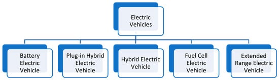
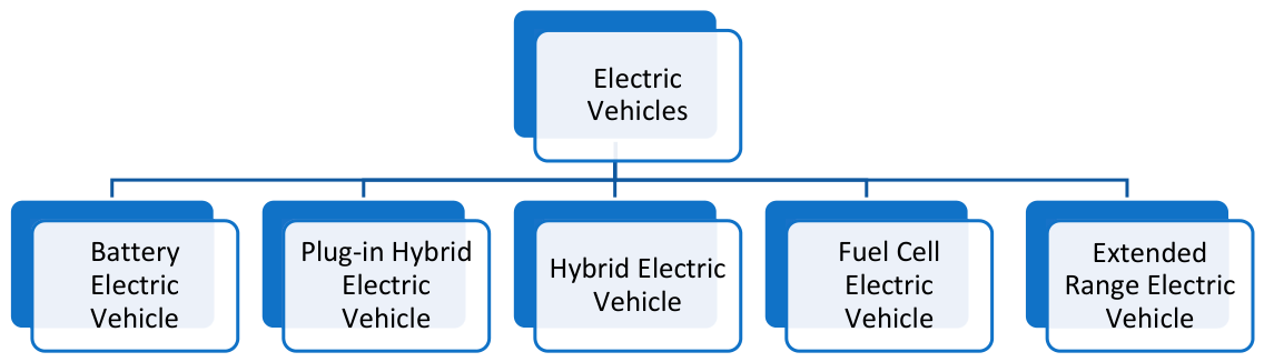
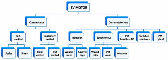
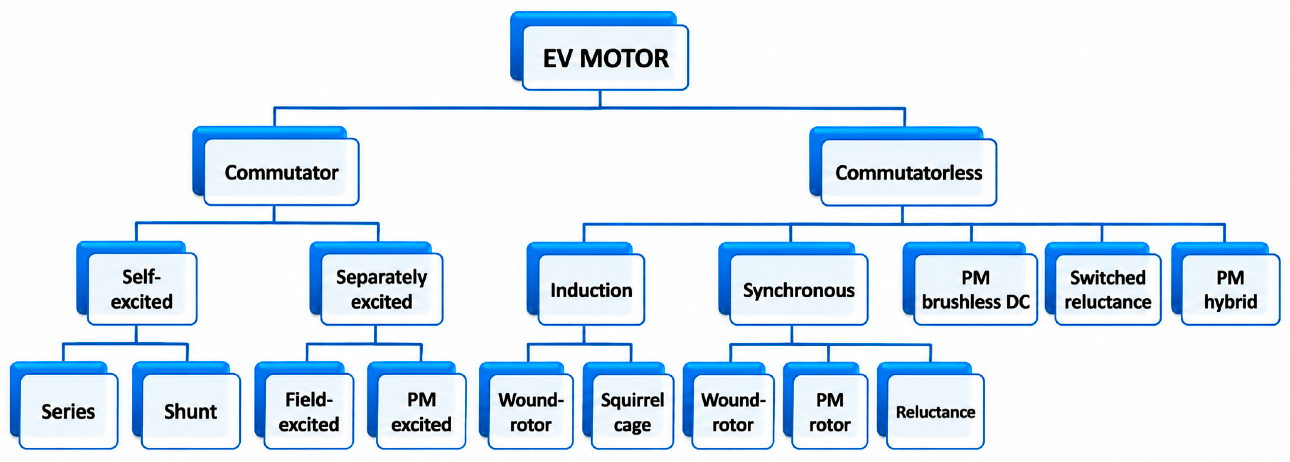
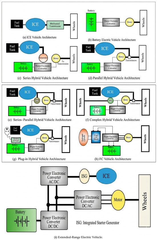
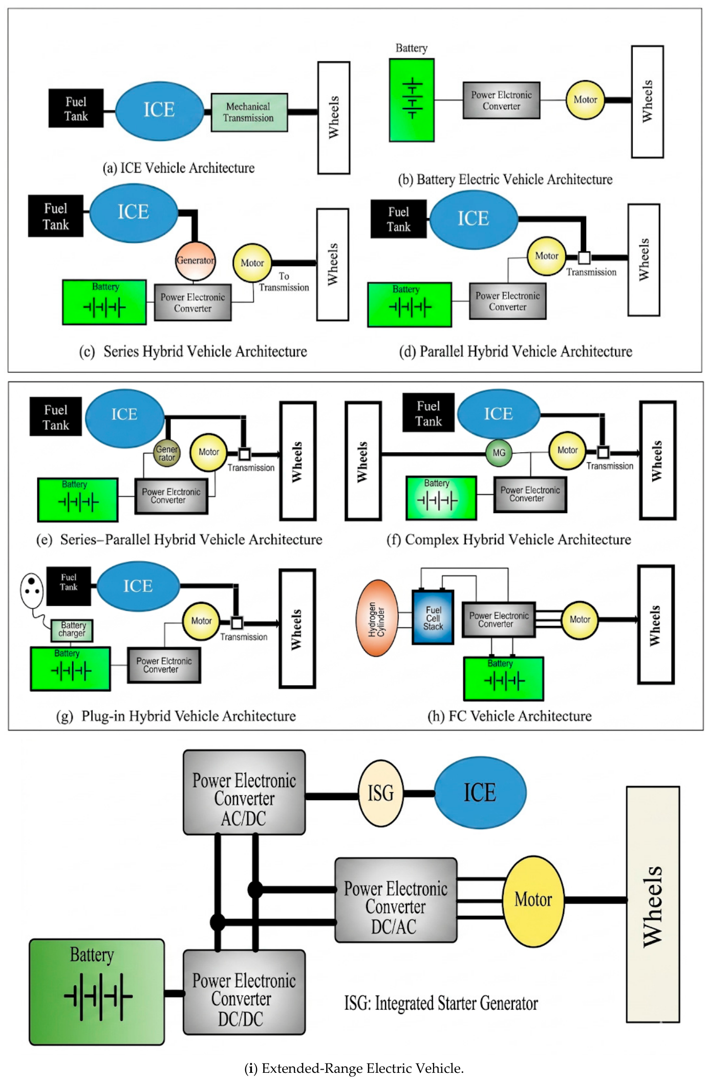
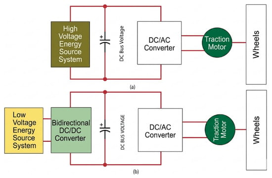
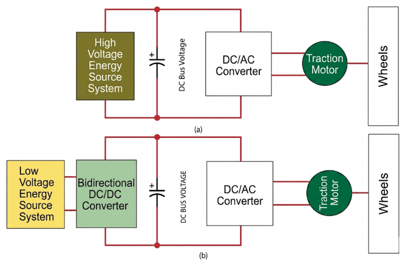
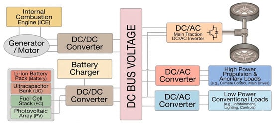
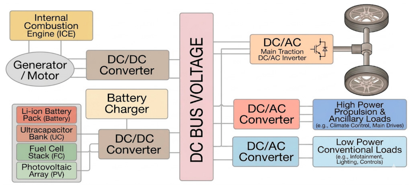
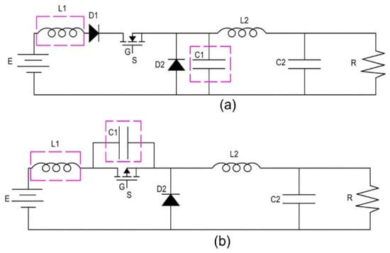
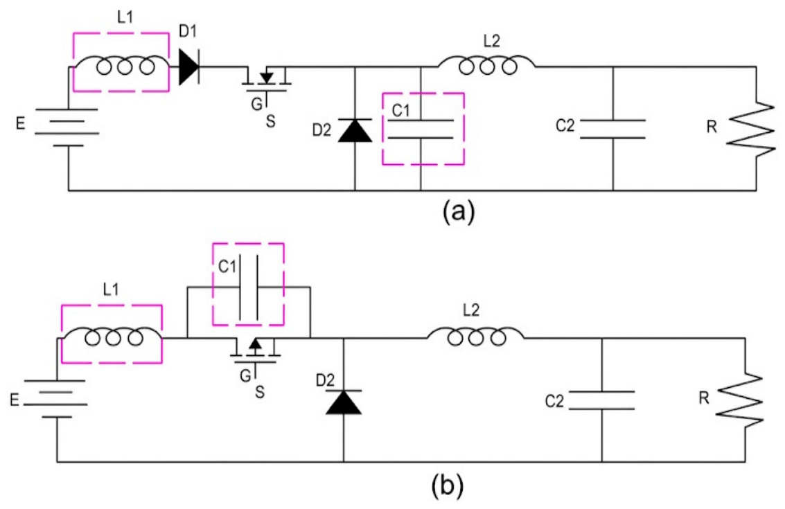
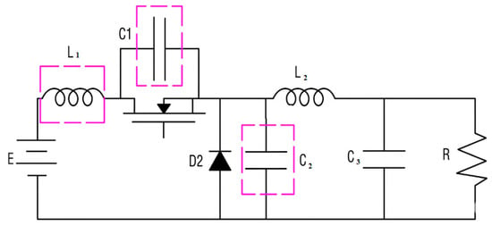
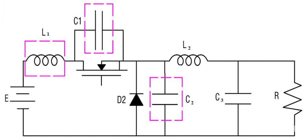
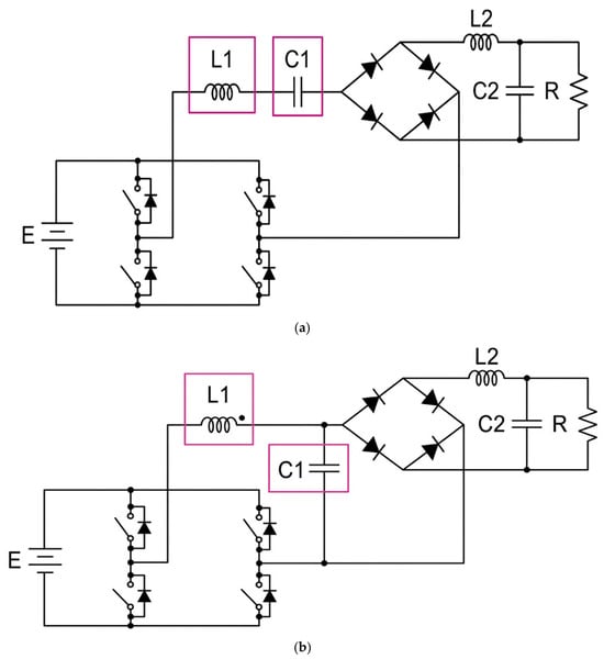
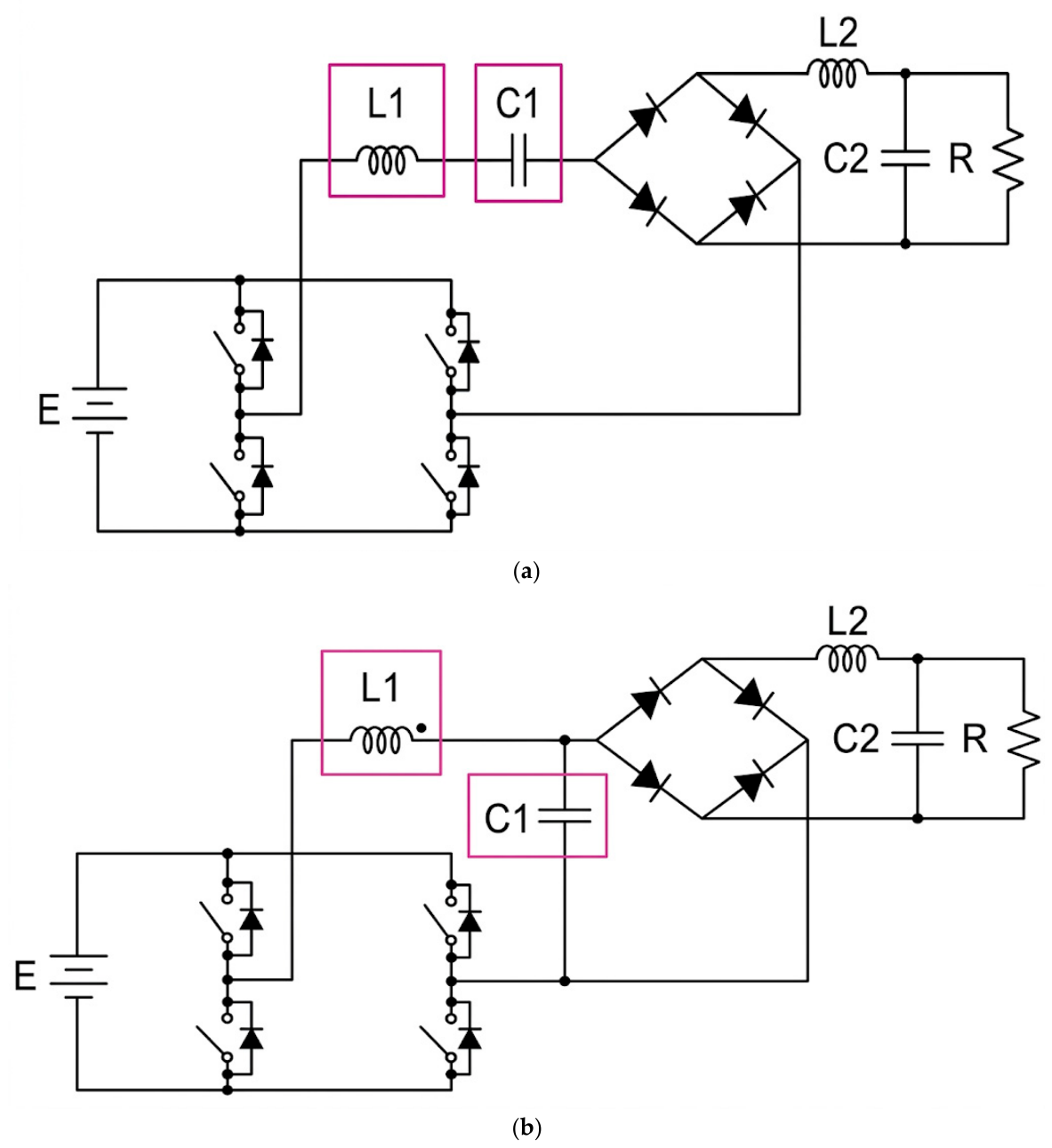
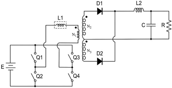
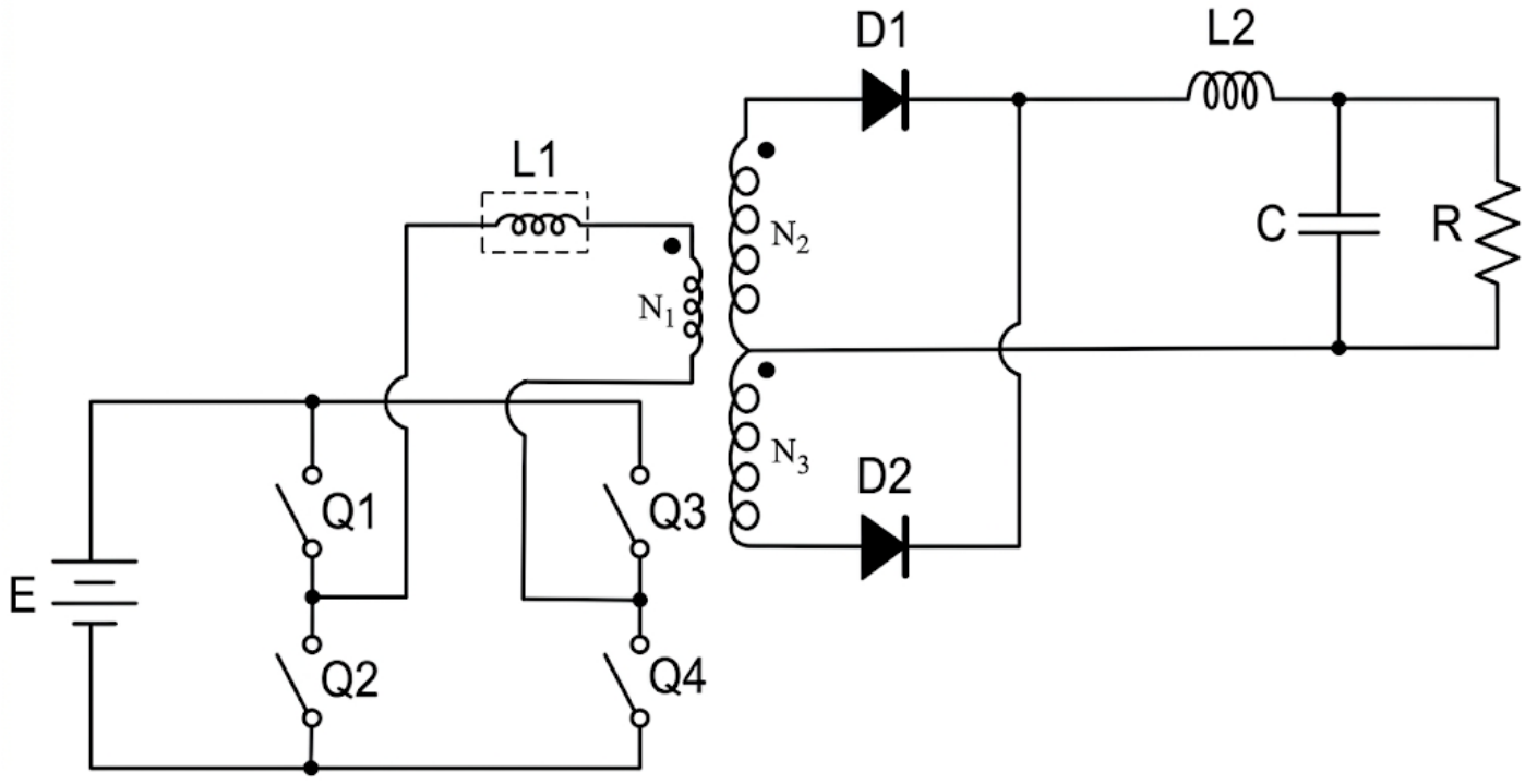
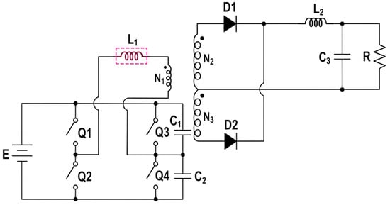
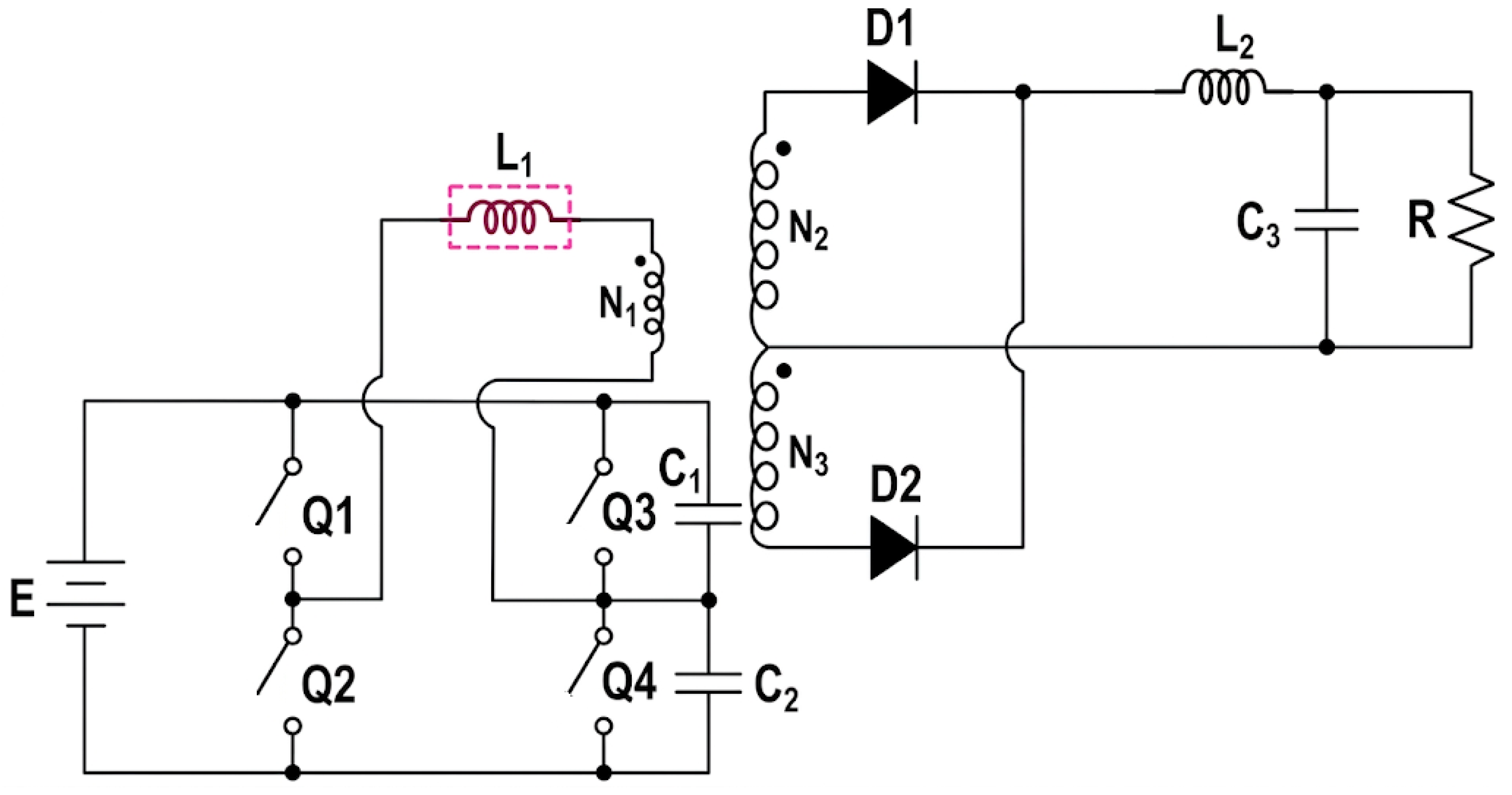
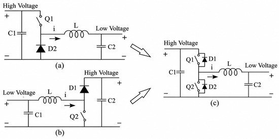
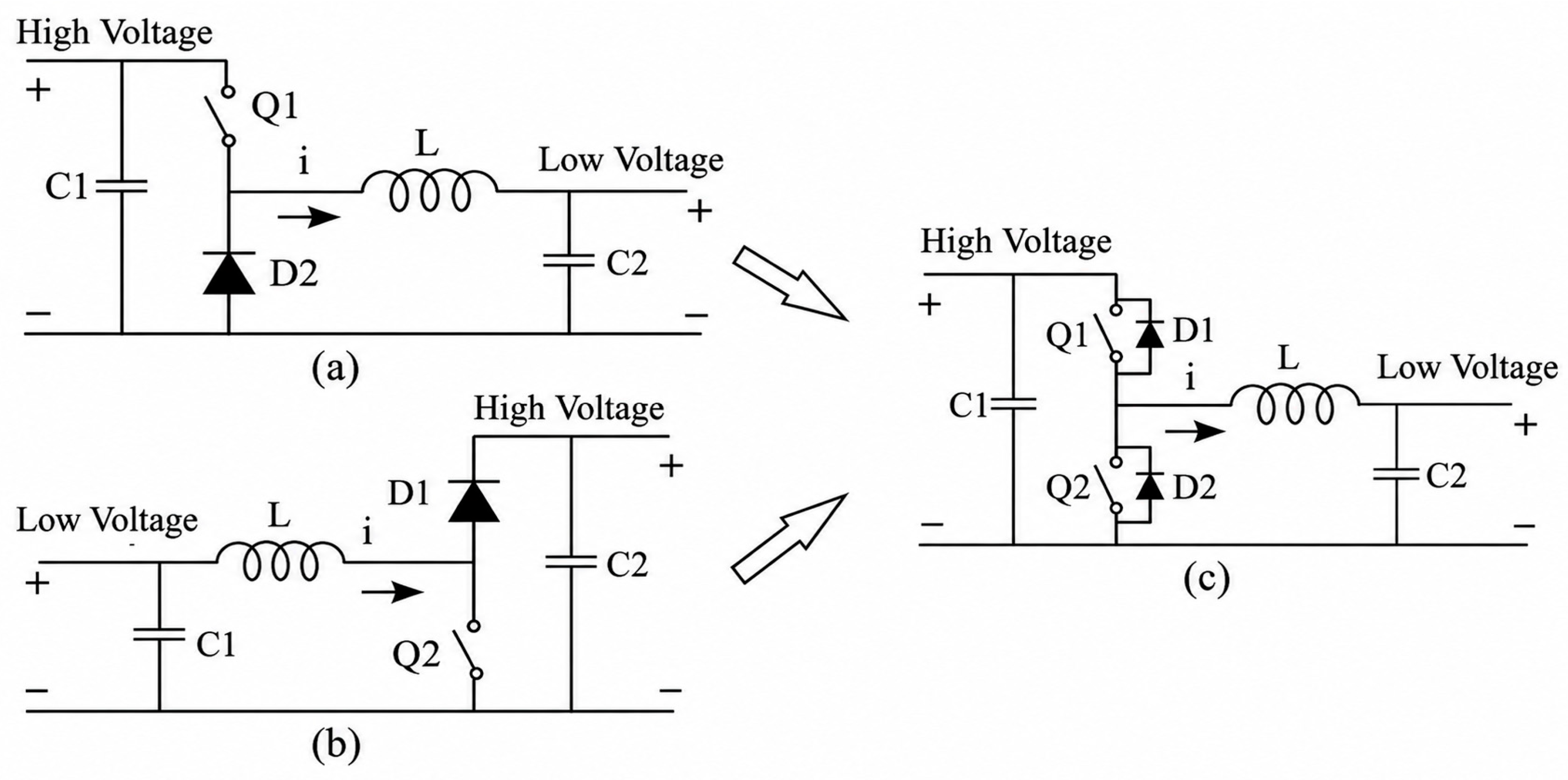
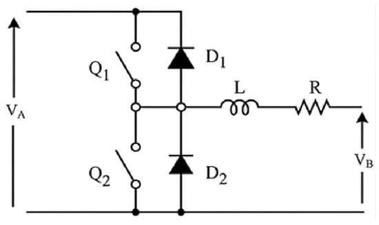
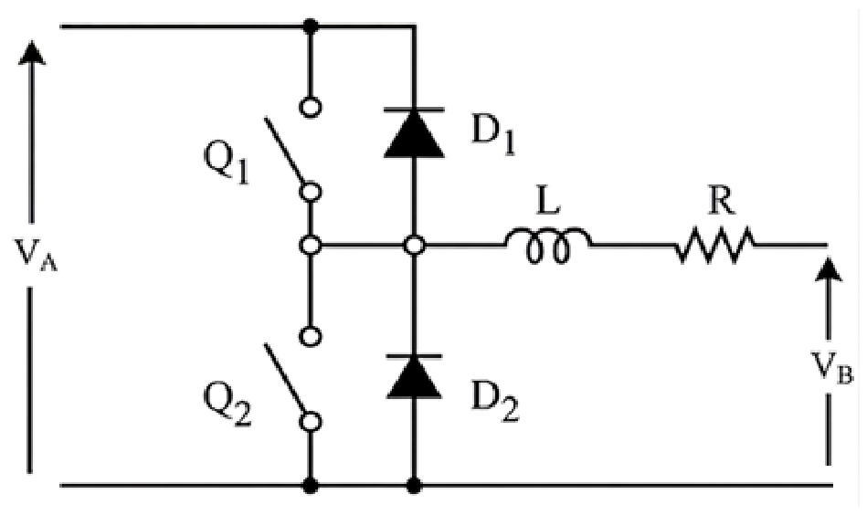
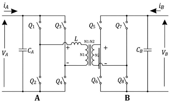
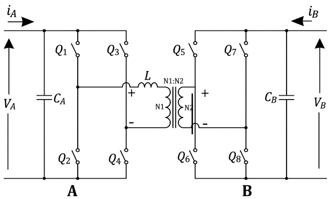
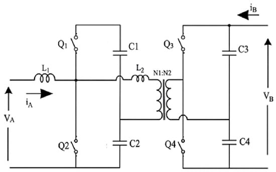
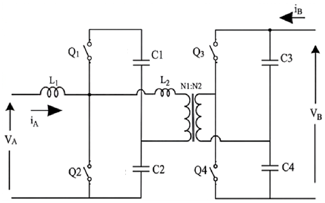
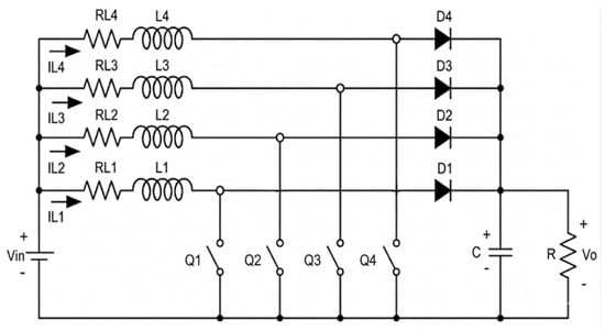
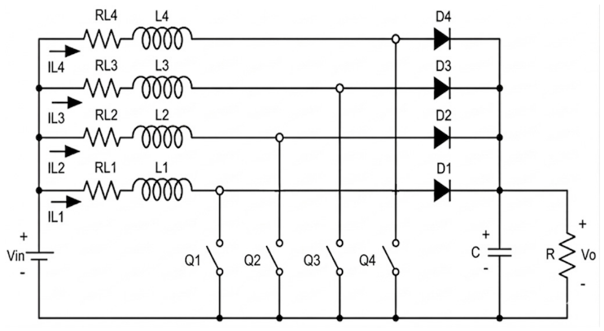
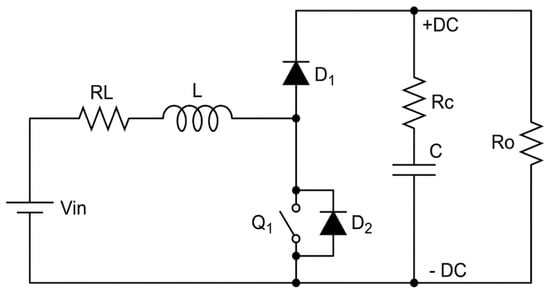
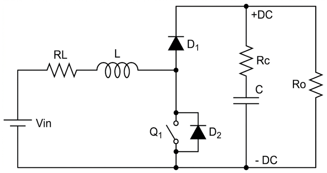
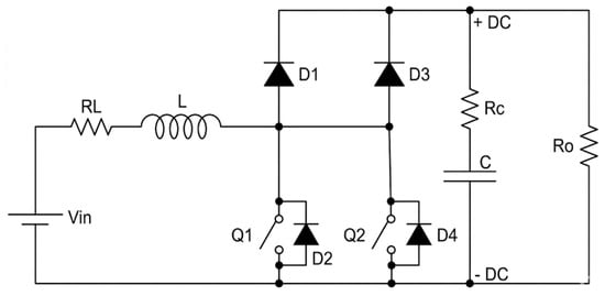
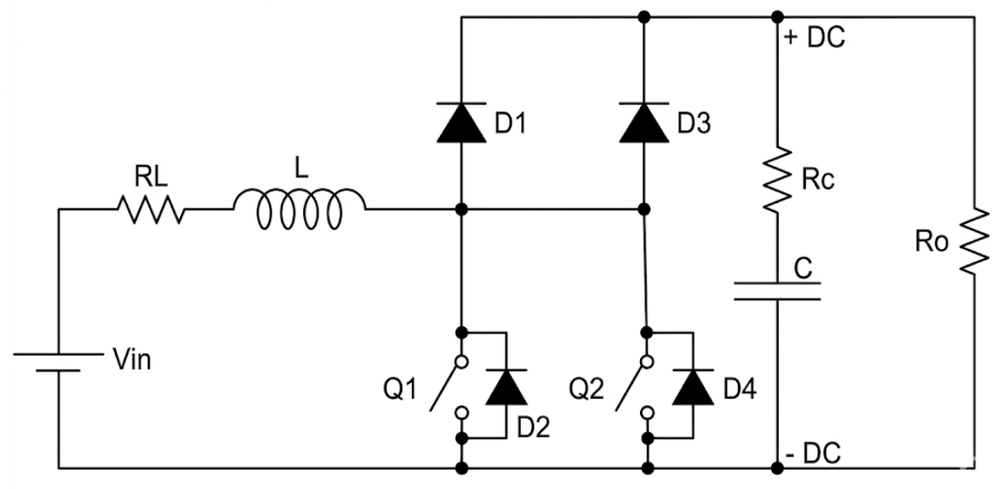
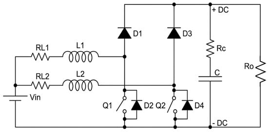
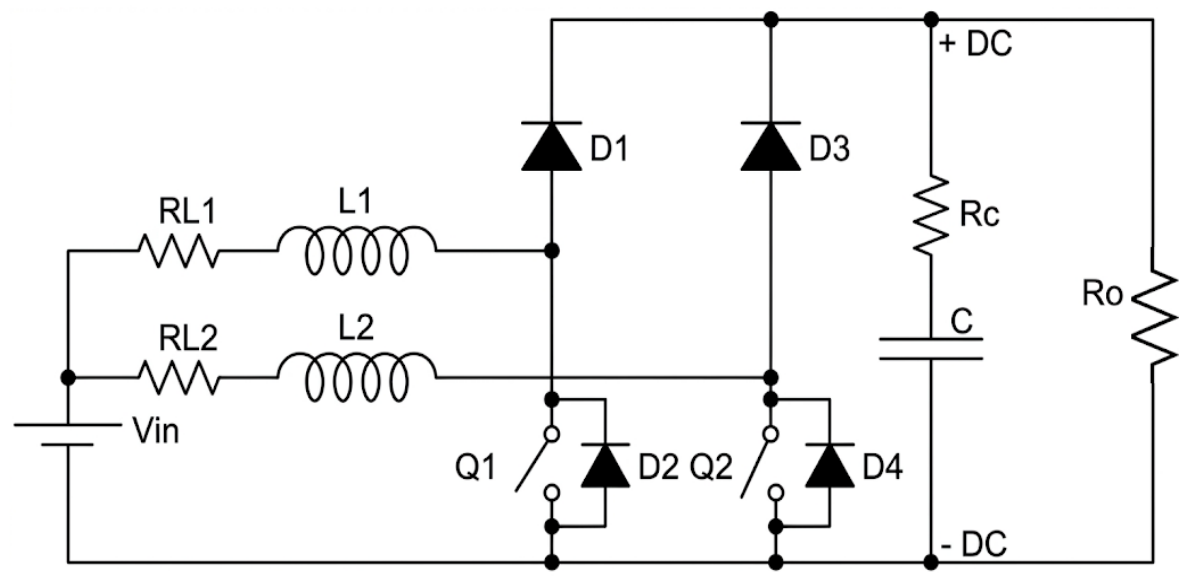
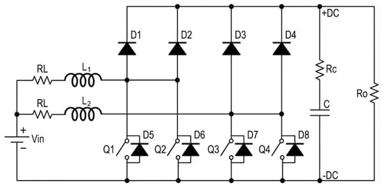
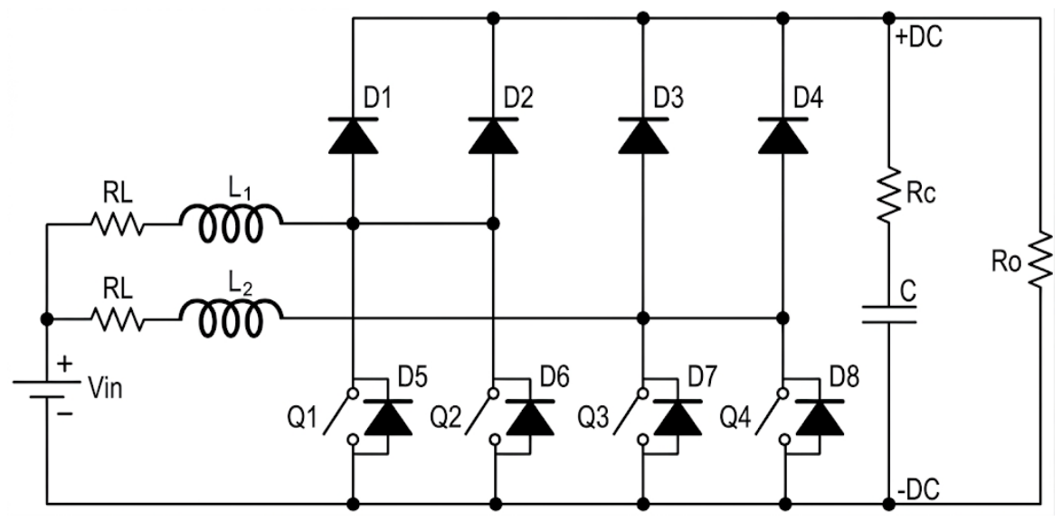
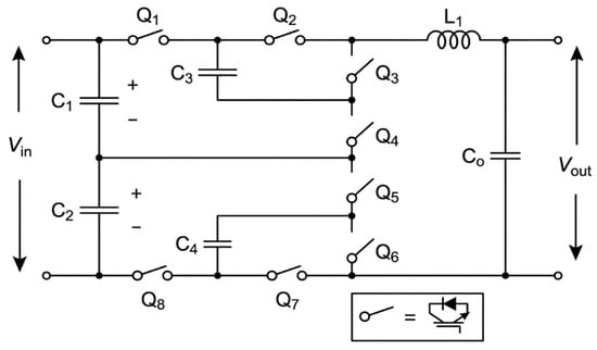
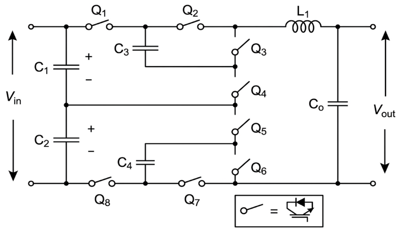
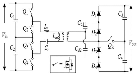
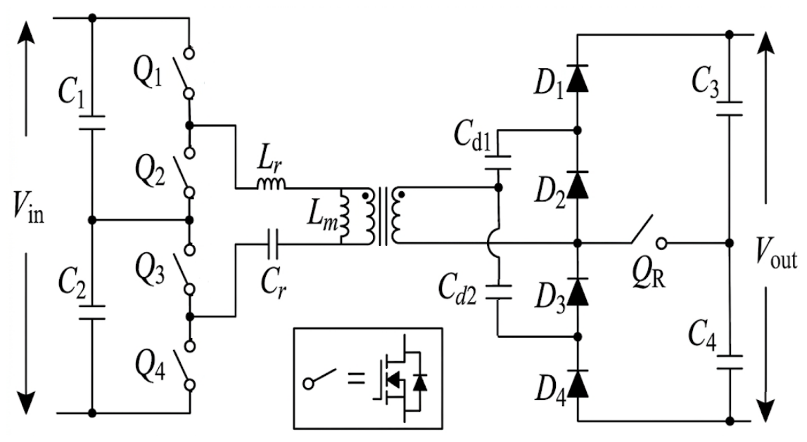
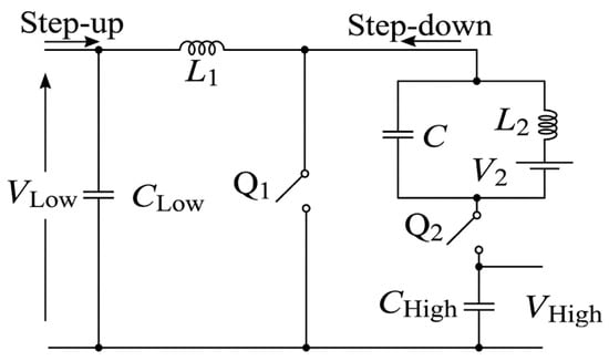
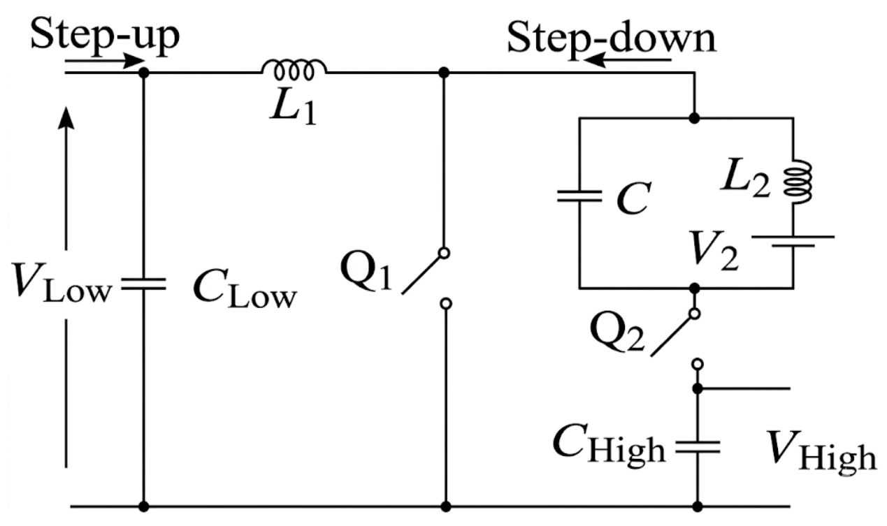
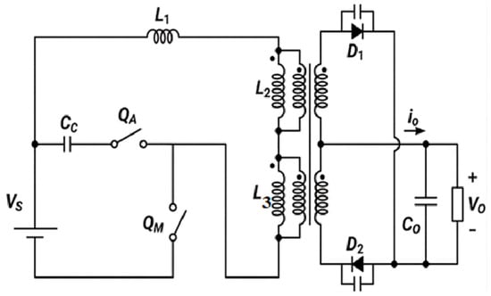
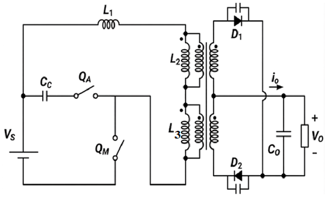
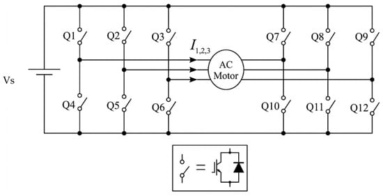
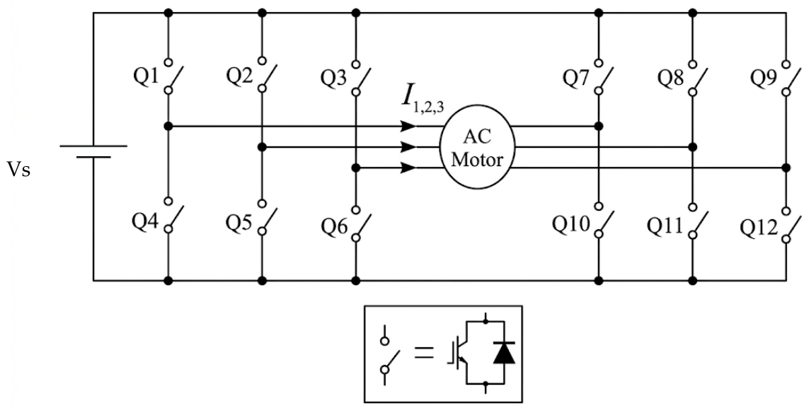
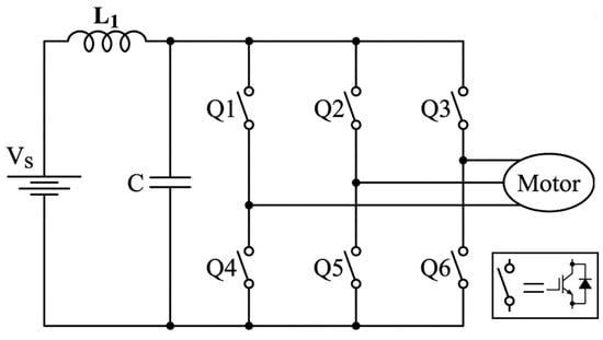
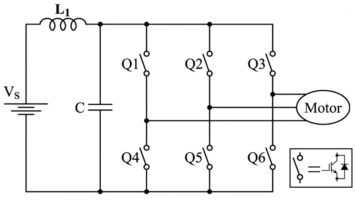
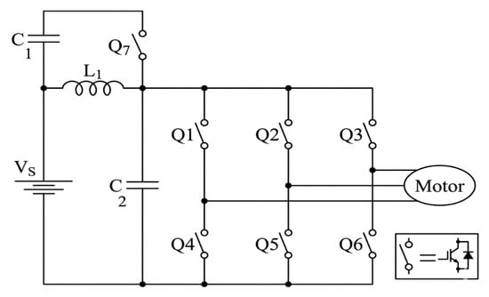
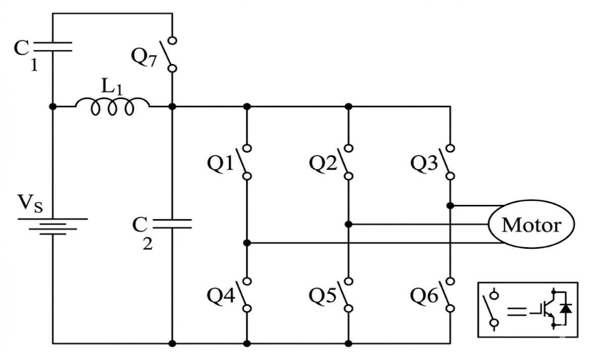
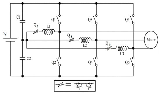
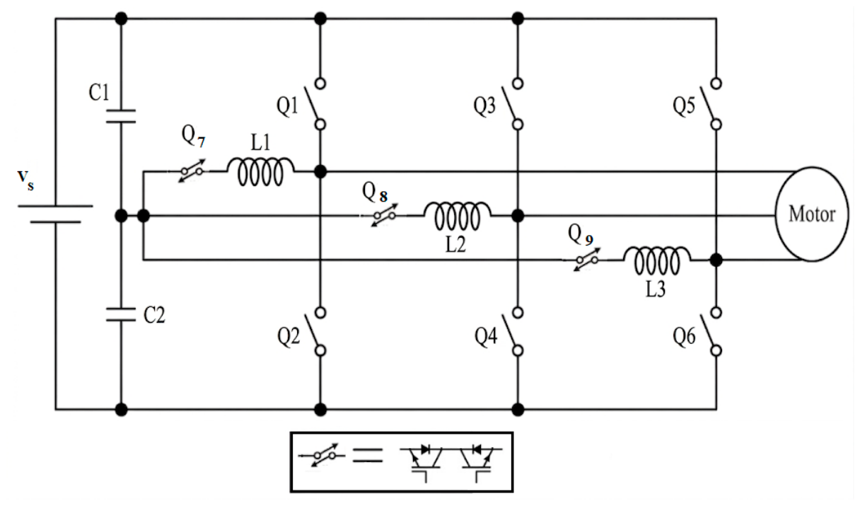
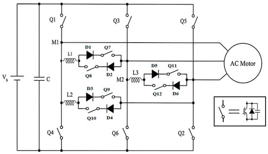
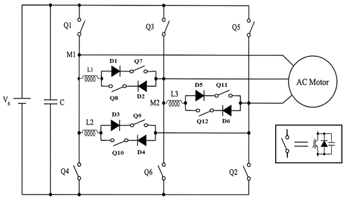
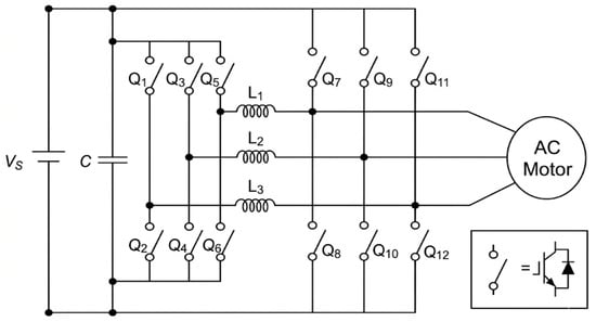
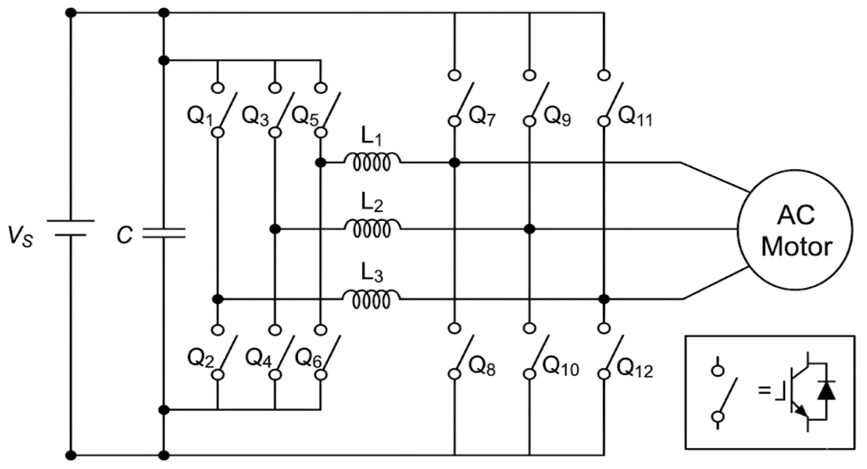
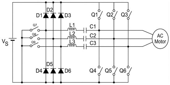
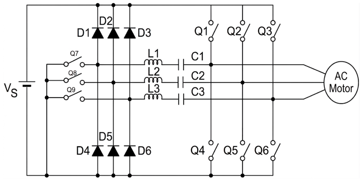
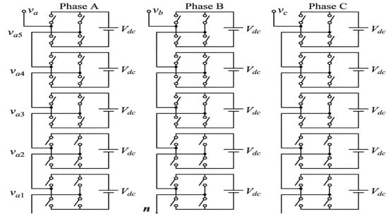
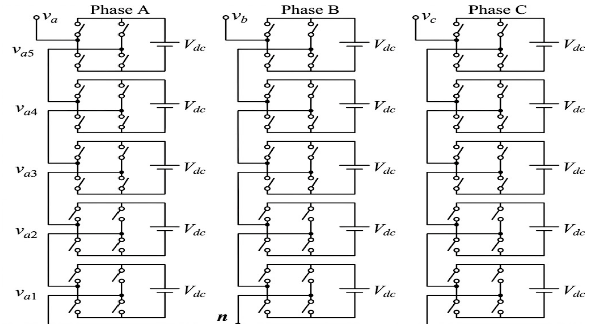
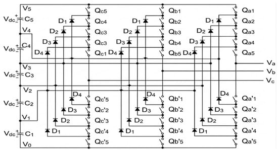
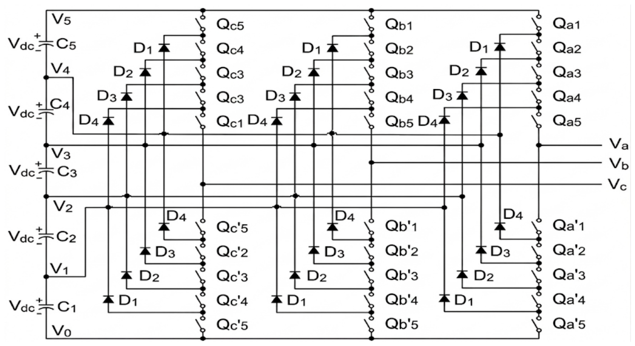
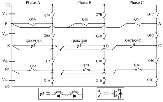
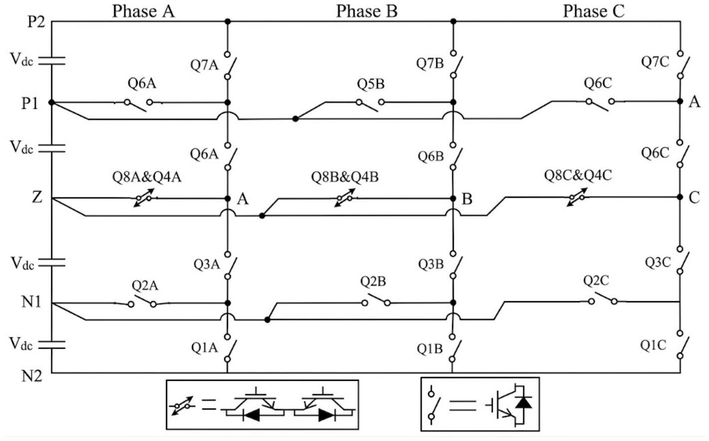
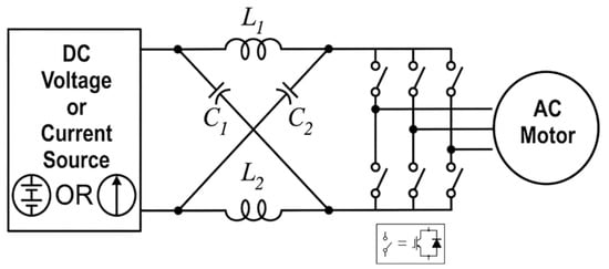
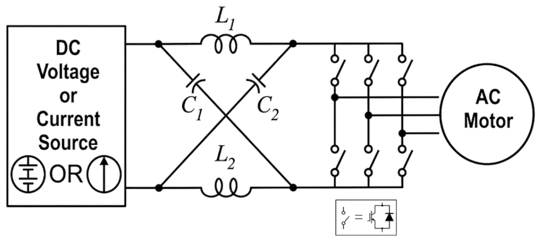
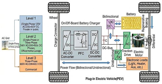
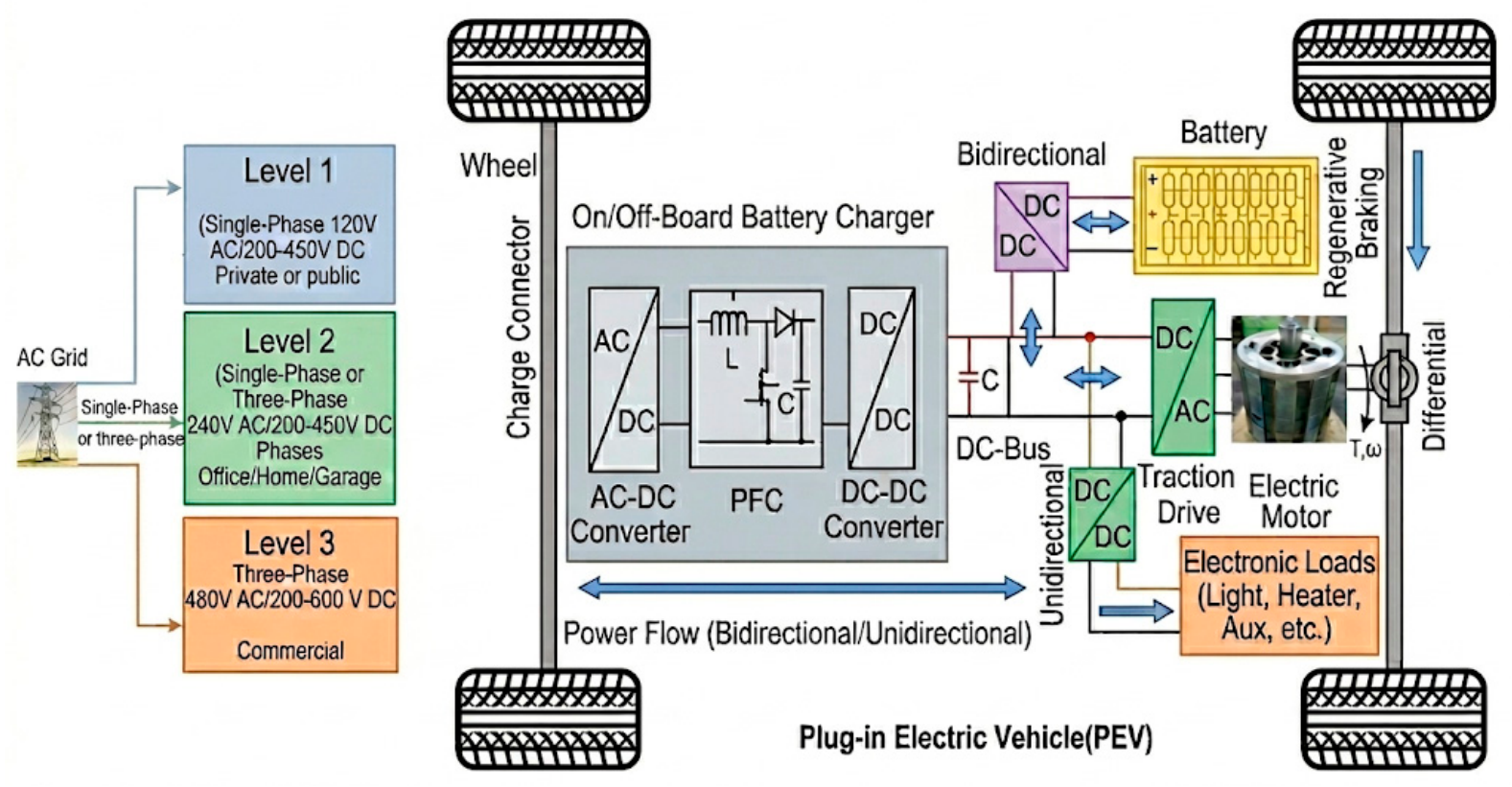
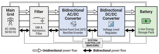
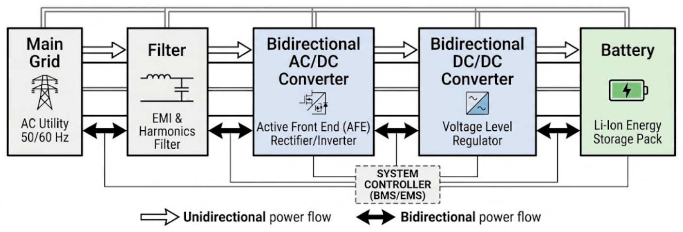
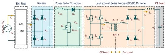
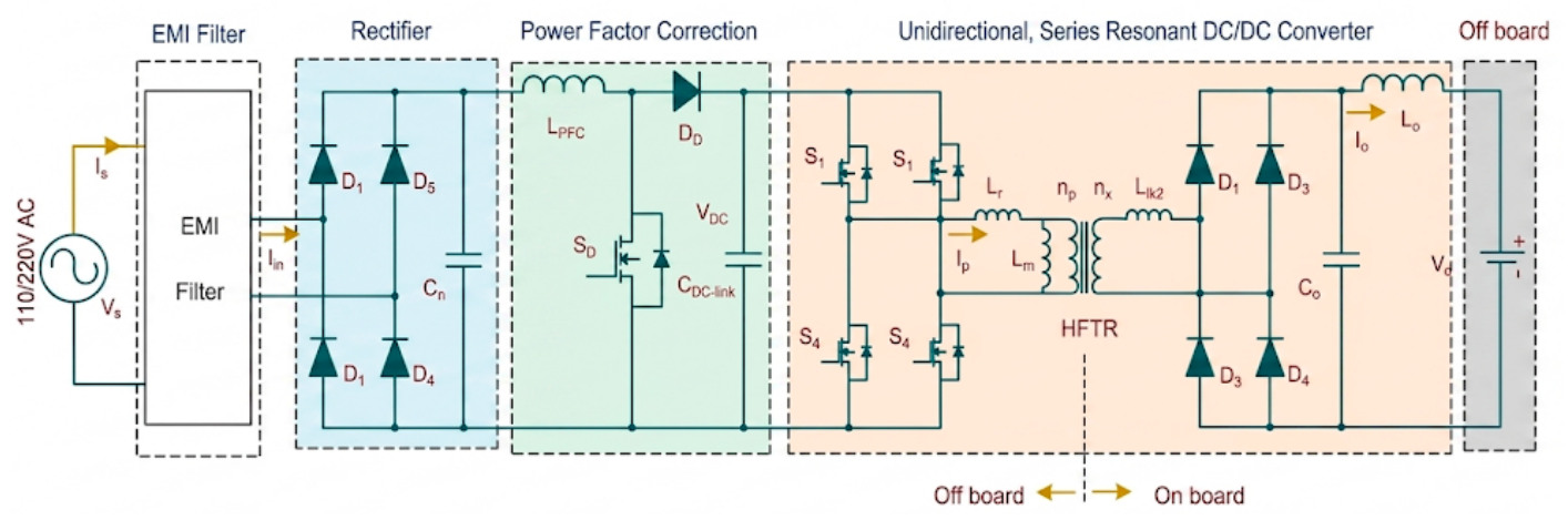
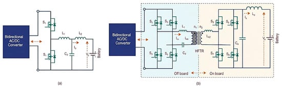
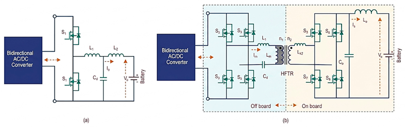

Disclaimer/Publisher’s Note: The statements, opinions and data contained in all publications are solely those of the individual author(s) and contributor(s) and not of MDPI and/or the editor(s). MDPI and/or the editor(s) disclaim responsibility for any injury to people or property resulting from any ideas, methods, instructions or products referred to in the content. |
© 2026 by the authors. Licensee MDPI, Basel, Switzerland. This article is an open access article distributed under the terms and conditions of the Creative Commons Attribution (CC BY) license.