


Abstract
The paper presents an optimal control strategy selection for an induction motor during voltage start-up, focusing on limiting the maximum current and starting torque surges at a given start-up time. Optimizing the operation of a soft-start system can be achieved using a simple system that assumes a linear voltage increase from a specific initial value. The advantage of this approach is the elimination of transducer systems for measuring voltages and currents. That approach requires simulating the drive system to select the optimal variant for a given system based on maximum and minimum torque values, maximum current, and optimal starting time. Transient calculations, for example, for the induction motor, were performed using both the analytical and circuit-field methods for different U/f time characteristics under varying motor load conditions, and the simulation results were compared with measurements.
1. Introduction
Induction motors are the most widely used motors due to their reliability, robustness, and low cost. More than 85% of industrial motors in use today are induction motors. During the direct start-up of an induction motor (DOL), the stator current increases several times. DOL start-up can therefore cause several adverse effects on the motor and the supply network, such as a shorter service life of the coupling element during frequent start-ups, as well as the motor itself, and voltage drops in the supply network, especially in the case of a weak power system [1,2,3,4]. For this reason, various methods are employed to address these issues. The most commonly used methods involve reducing the supply voltage. Classically used techniques, such as star/delta switches, part-winding starting, resistor/reactor starting, and auto-transformer starting, are currently not recommended. Generally, among the offered electronic solutions, we can distinguish between those that change the effective value of the supply voltage by controlling the switching phase and typical PWM systems that can control both the effective value and the frequency of the supply voltage. The first of these solutions is known as soft-start systems. Soft-start systems are commonly used in industrial applications where a constant rotational speed is required, and PWM frequency control is unnecessary. They are primarily used for systems with quadratic dependence of the load torque on speed, such as fans and pumps; for systems with high inertia, such as circular saws or mills; and for systems with almost constant load torque, such as the gypsum crusher [5]. It should be emphasized that these systems are used not only to improve starting but also to brake high inertia loads.
Additionally, their energy efficiency during network operation is outstanding, owing to bypass contactors, and they are cost-effective relative to comparable simple frequency converters, particularly in the range of rated power from a few to a thousand kilowatts. A comprehensive discussion of different starting methods is given in [6]. For high-power, high-voltage motors, we can also mention motor stator-winding series liquid resistance, soft starting, and magnetic-saturation reactor voltage reduction for soft starting [7,8,9]. Despite their long history, soft-start systems remain a subject of interest to researchers. In [10], a control method for soft starters is presented that combines the advantages of firing-angle-based and predictive methods. In [11], a novel voltage observer based on a voltage-sensorless technique that uses measured motor phase current and plant knowledge is presented. In [12], a new soft-start control scheme based on an artificial neural network is presented, designed to maintain a constant accelerating torque. Similar issues concerning soft start are discussed in [13,14,15,16,17], where solutions with switches in only two phases are also encountered [14]. Thyristors are commonly used as control elements. By switching off part of the voltage sinusoid, it is possible to regulate the first-harmonic voltage, which determines the generated torque. The primary goal is to limit the current drawn by the motor from the mains. The use of a thyristor switch causes voltage waveform distortion and the appearance of higher torque harmonics. Hence, several studies have investigated the selection of thyristor turn-on angles to minimize these unfavorable effects. These include [10], Ref. [18] using special fuzzy control, Ref. [19] using a control algorithm to reduce the initial torque pulsation and high inrush current by exponentially decreasing the firing angle, and [20], where starting torque pulsations are eliminated by triggering back-to-back-connected thyristors at appropriate points on the first supply voltage cycle. Optimal voltage trajectory control and adaptive control of the transistor turn-on angle using predictive methods, artificial intelligence, and fuzzy logic were also addressed in [21,22,23,24,25,26,27,28,29,30]. Such intelligent control enabled reduced torque pulsation [30], optimized speed trajectory, and reduced start-up losses [28].
What was missing until now was the foundation for control methods grounded in accurate analytical and numerical models. Simulation models were primarily based on d-q models with constant parameters [31,32], most often implemented in the MATLAB/Simulink environment, i.e., simplified models that did not account for nonlinear phenomena in the motor [11,33]. This approach places the primary burden on increasingly sophisticated control methods and systems, which are expensive and not always applicable, particularly in industrial environments and for high-power machines. Therefore, the authors focused on a method for controlling the start of an induction motor using soft-start, employing a control scheme without voltage or current transducers and relying solely on the linear increase in effective voltage from an appropriately selected initial value and its rise time. This approach provides a simple means of achieving the required limits on maximum current and starting torque while ensuring the shortest possible start-up time. However, this requires rapid, multivariate, yet accurate calculations of the induction motor’s dynamic states, which is only possible with an extensive analytical model that accounts for nonlinear phenomena in the motor. The authors previously addressed modeling dynamic states in [34]. There, they developed and experimentally validated methods for the analytical simulation of phenomena in an induction motor under direct-on-line and frequency-starting conditions. To verify the accuracy of such a model, experimental results are not always feasible, especially under industrial conditions; therefore, a field-circuit model based on the FEM method can be used.
Simulation of the dynamic states of induction motor operation using field-circuit models has long been performed, with the introduction of slotted elements that facilitate consideration of rotor motion [35,36]. It is also possible to model dynamic states when the motor is powered by converter systems, especially PWM [37,38,39]. However, articles using FEM found in the literature primarily concern direct motor starting [40,41,42,43].
Only articles on doubly fed motors include FEM analysis of soft-start systems [44].
The authors present a full implementation of the FEM field-circuit model for controlling an induction motor via a soft-start system. This enables a comprehensive analysis of motor phenomena during both direct and soft-start starting, as well as verification of the developed circuit model.
2. Research Object
The main object of the study was a three-phase, eight-pole induction motor with a shaft height of h = 160 mm, a rated power of 7.5 kW, a rated voltage of 400 V (windings connected in a delta configuration), and a rated current of 16.6 A.
The basic rated parameters and main dimensions of investigated motors are given in Table 1.
Table 1.
The basic rated parameters and main dimensions of investigated motors.
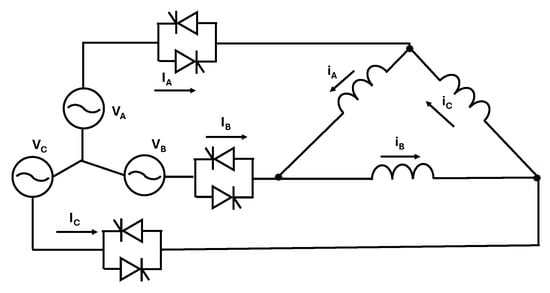
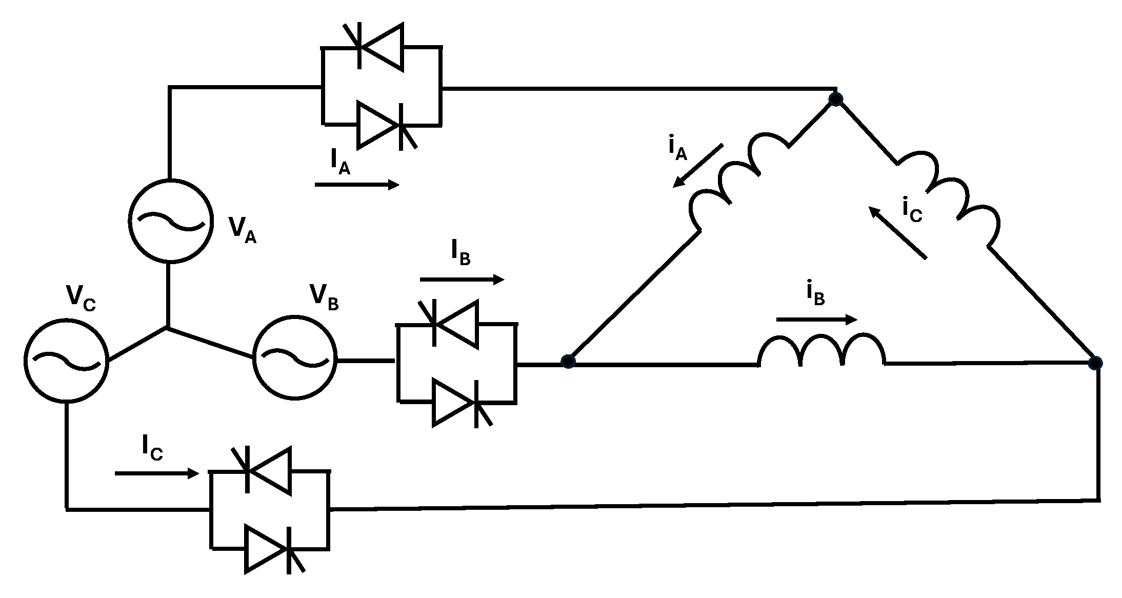
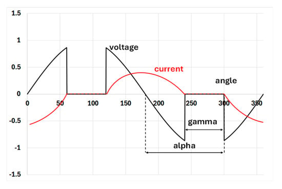
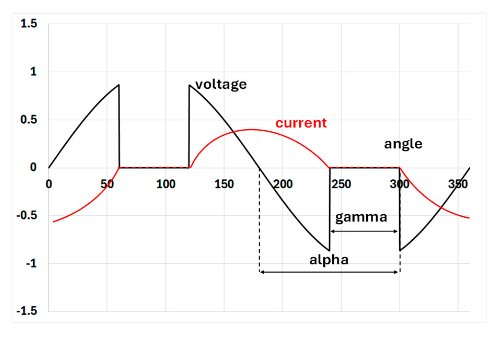
The induction motor was powered by a soft starter rated at 18.5 kW and a three-phase voltage of 400 V. A delta-connected motor is powered during startup from a soft-start circuit. In this case, the thyristors controlling the circuit are connected in series with the line wires supplying the motor. The circuit is shown in Figure 1. The soft-start system modifies the voltage waveform by switching off a specific phase using a thyristor. Switching off occurs when the current flowing through the thyristor crosses zero in the absence of a control pulse at the thyristor gate. Figure 2 shows a typical voltage waveform and two control methods based on alpha and gamma angles.
Figure 1.
Diagram of a soft-start system for delta-connected motor windings.
Figure 2.
Principle of operation of the soft-start system.
In the first case, the angle is measured from the moment the voltage crosses zero, while in the second case, the current crosses zero. Depending on the angle, the first harmonic of the distorted voltage waveform is reduced, resulting in a corresponding decrease in motor current. Of course, the motor’s electromagnetic torque also decreases; hence, the system’s natural application is in drives with fan-like load torque characteristics.
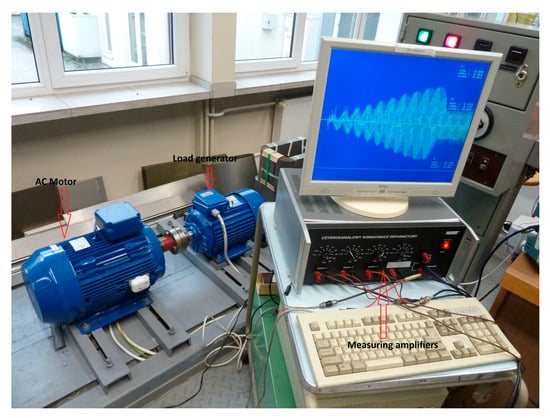
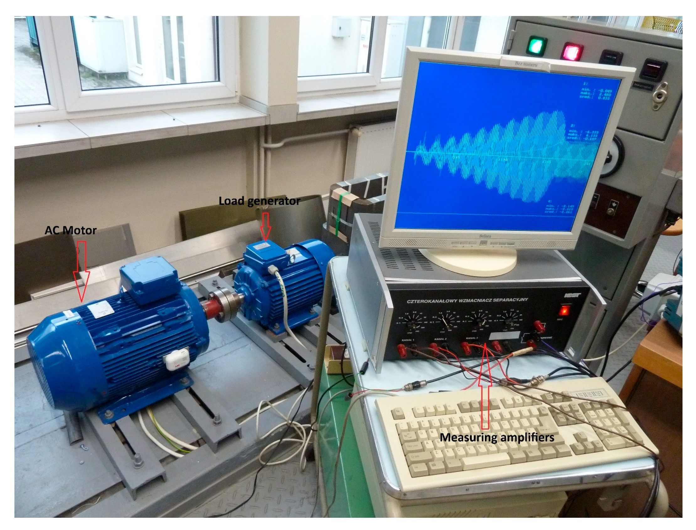
The measurement setup is shown on Figure 3. Measurements were performed for various starting-voltage values and voltage-rise times set in the soft starter. During the measurements, waveforms of the supply voltage, motor line current, and rotational speed, obtained using a tachometric generator, were recorded as functions of time. A four-channel measurement system was used to record the results.
Figure 3.
A test stand for testing an induction motor powered by a soft-start system.
3. Field-Circuit Simulation
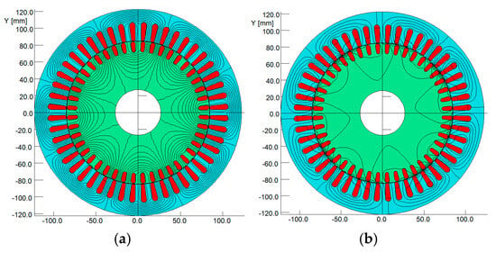
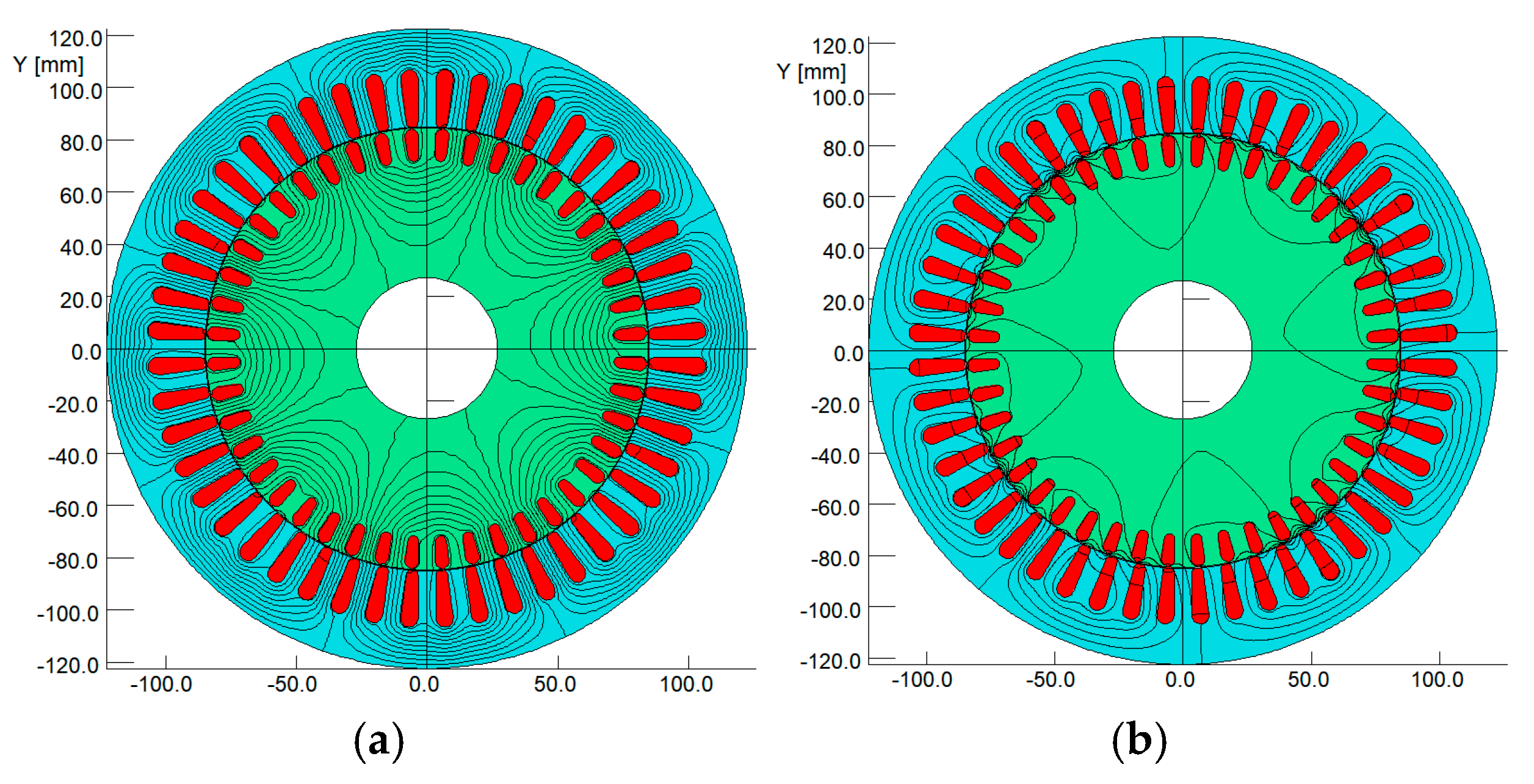
The field-circuit model was used to simulate the motor operation, taking into account the actual configuration of the windings and the rotor cage, taking into account the rotor motion thanks to the use of a gap element that allows for the connection of the stator and rotor finite element meshes and avoids changing the mesh topology during rotor rotation. Figure 4 illustrates the motor numerical model and magnetic field lines for both no-load and short-circuit steady-state operations, enabling verification of the model’s accuracy.
Figure 4.
Isolines of the magnetic vector potential (field lines) in a tested motor at no-load (a) and in a steady short-circuit condition (b).
Based on the developed models, two types of simulations were conducted: the first with the motor powered by a sinusoidal voltage with modulated amplitude, and the second with a power supply from a real converter system, which, by cutting off a portion of the voltage sinusoid, reduced the amplitude of the first harmonic.
3.1. Simulation Results with the Motor Powered by a Sinusoidal Voltage
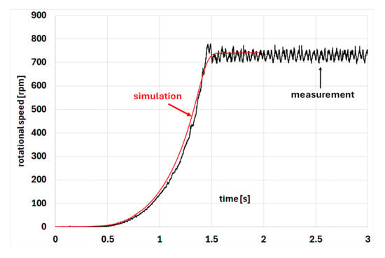
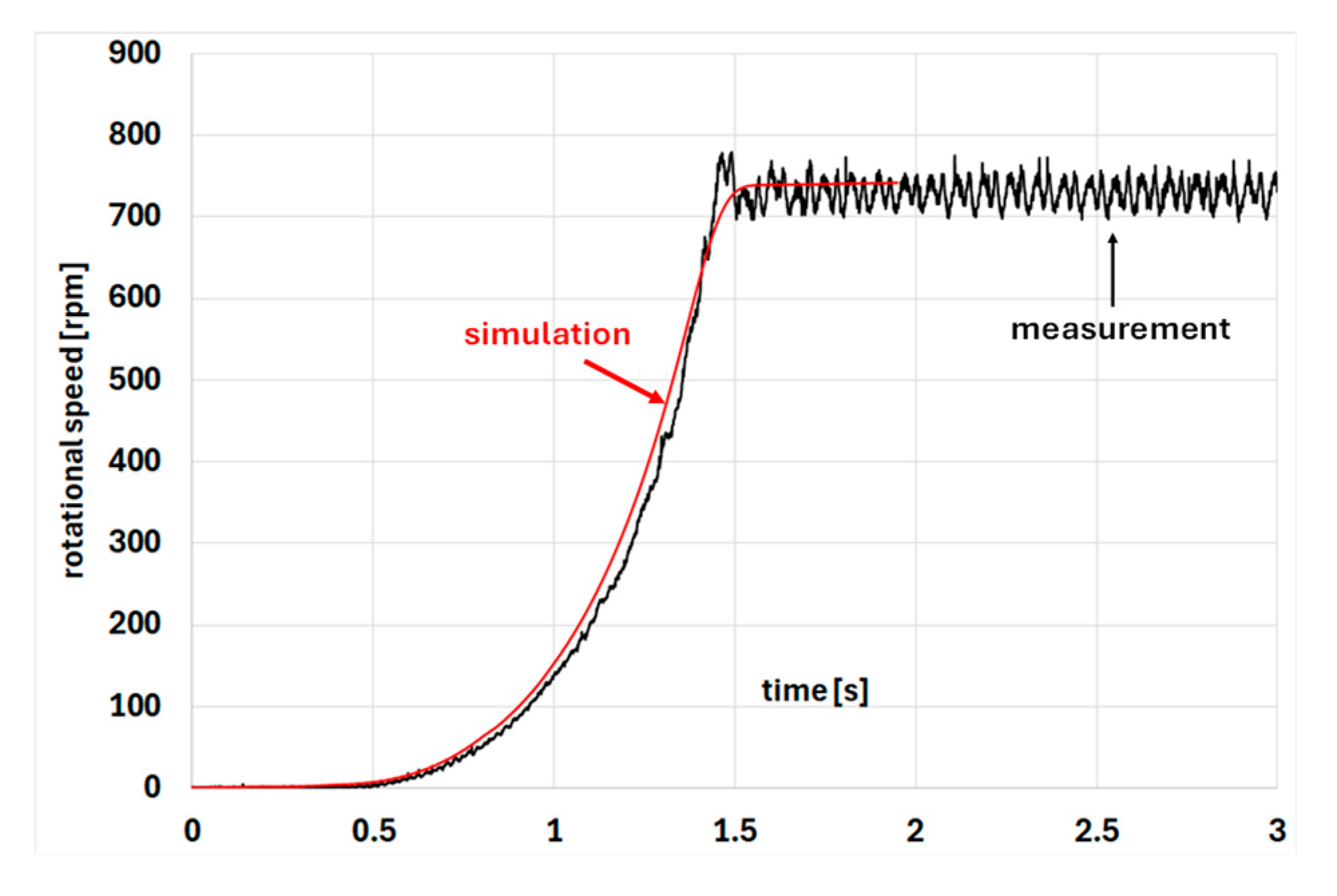
The first simulation modeled the starting state of a motor loaded solely with mechanical losses from the motor itself and the coupled permanent magnet generator. Initially, a voltage trajectory was used, starting at 20% of the rated voltage and gradually increasing to the rated value after 3 s. Figure 5 compares the calculated and measured motor speed trajectories for the tested system.
Figure 5.
Comparison of the calculated and measured motor speed trajectories in the test system.
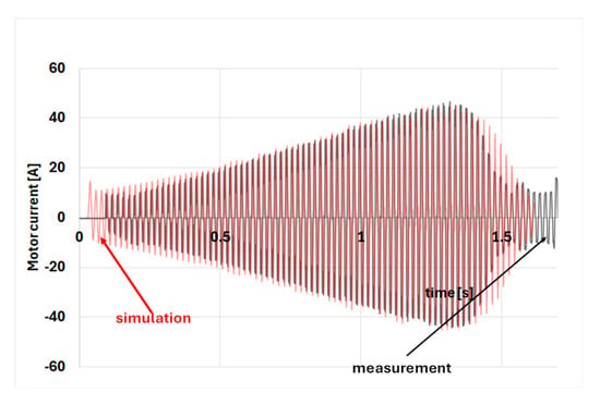
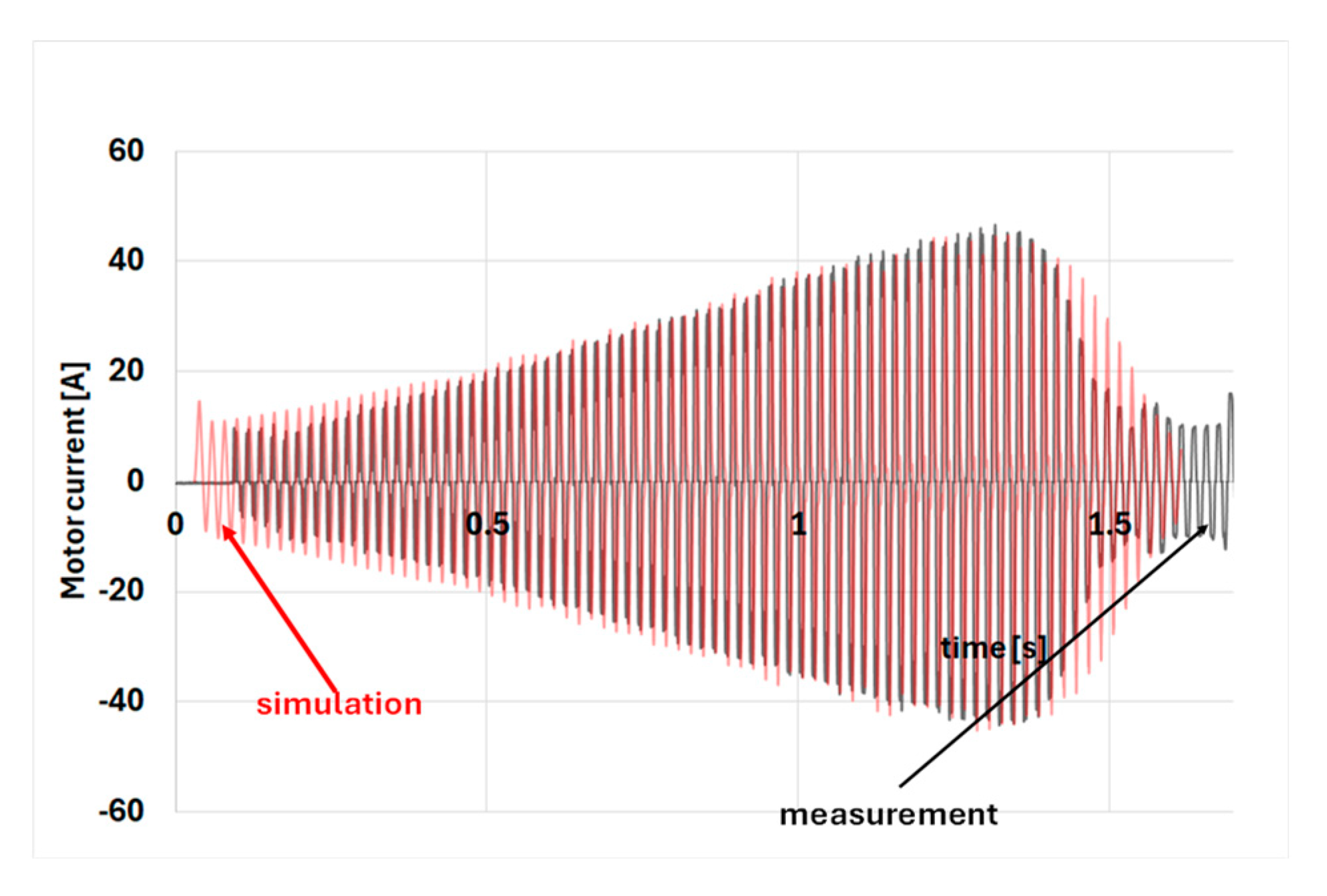
As shown in Figure 5, good agreement was achieved between the simulated and measured waveforms. In the initial part of the start-up, the speed is zero because the motor torque generated at the starting voltage is less than the static rolling resistance torque of the driven system. Figure 6 compares the simulated and measured line current (motor operating in delta connection).
Figure 6.
Comparison of simulated and measured line current.
The comparison shows good agreement between the two waveforms. The differences arise because, especially at the start of the start-up, the motor is supplied with a distorted voltage, whereas the simulation uses a sinusoid with variable amplitude, and because the simulation omits the current component due to the motor’s iron losses. Figure 7 shows the motor’s electromagnetic torque waveform during the start-up simulation.
Figure 7.
Electromagnetic torque of the motor during starting based on simulation.
As can be seen, despite the skewed slots in the tested motor (the simulation model uses a multilayer model that reproduces skew by connecting offset motor sections in series), an oscillatory component is visible in the torque waveform, resulting from the interaction between the stator and rotor slots.
3.2. Simulation Results with the Motor Powered by a Power Supply from a Real Converter System
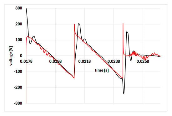
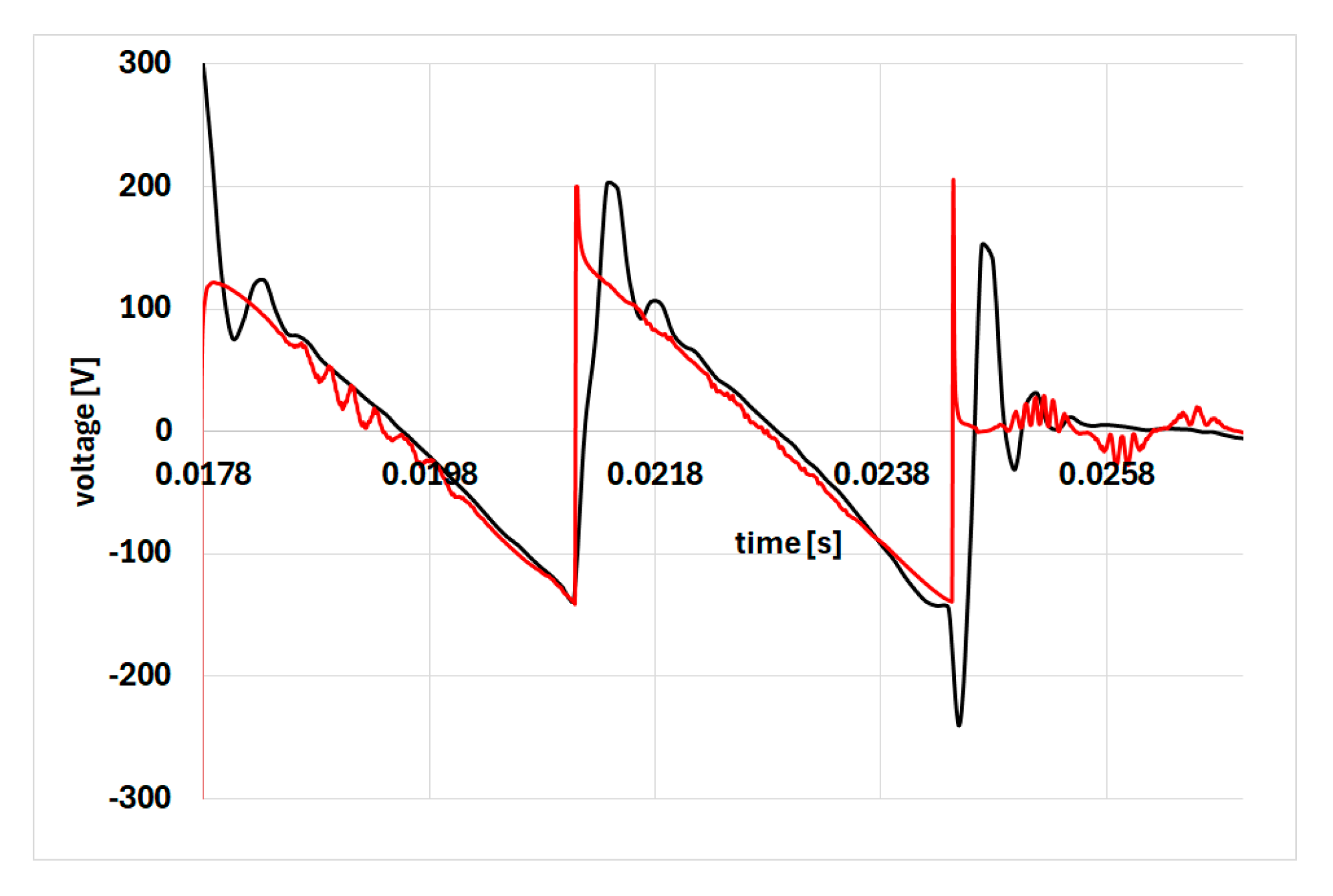
In the initial starting phase, the motor rotor is practically stationary. This simplifies calculations for a model that accounts for the actual voltage waveform generated by the converter system. In the initial starting phase, obtaining a low voltage requires cutting a large portion of the source voltage sinusoid. Figure 8 shows the line-voltage waveforms supplied to the motor during a selected time segment, during which the source-voltage control remains virtually constant.
Figure 8.
Waveforms of the line voltage that powers the motor; comparison of measurement (red line) and simulation (black line).
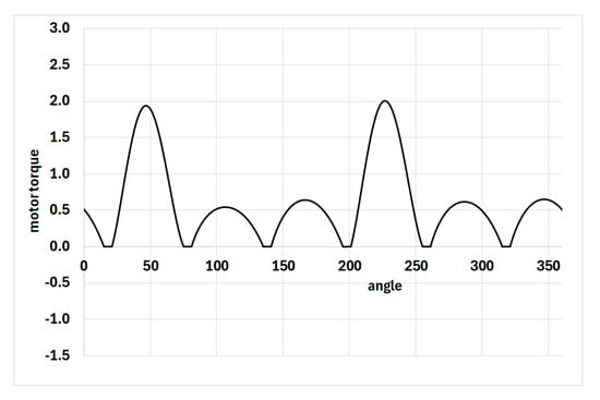
As shown in the comparison, the control method identification is correct. For the measured waveform, we observe overvoltages occurring when the powered winding is turned off. In contrast, for the simulated waveform, oscillations result from the modeling of switches that simulate the operation of two connected transistors. Figure 9 shows the simulated waveform of the electromagnetic torque generated by the motor for this power supply method.
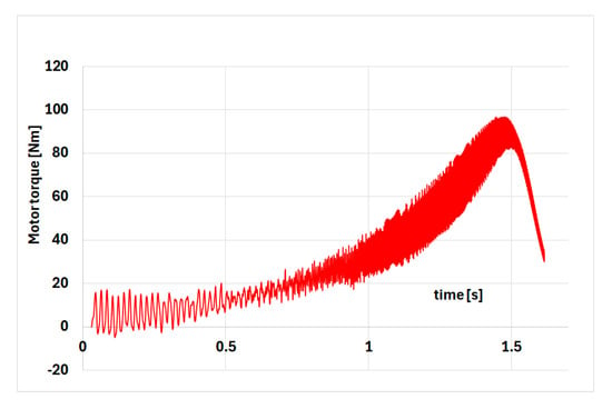
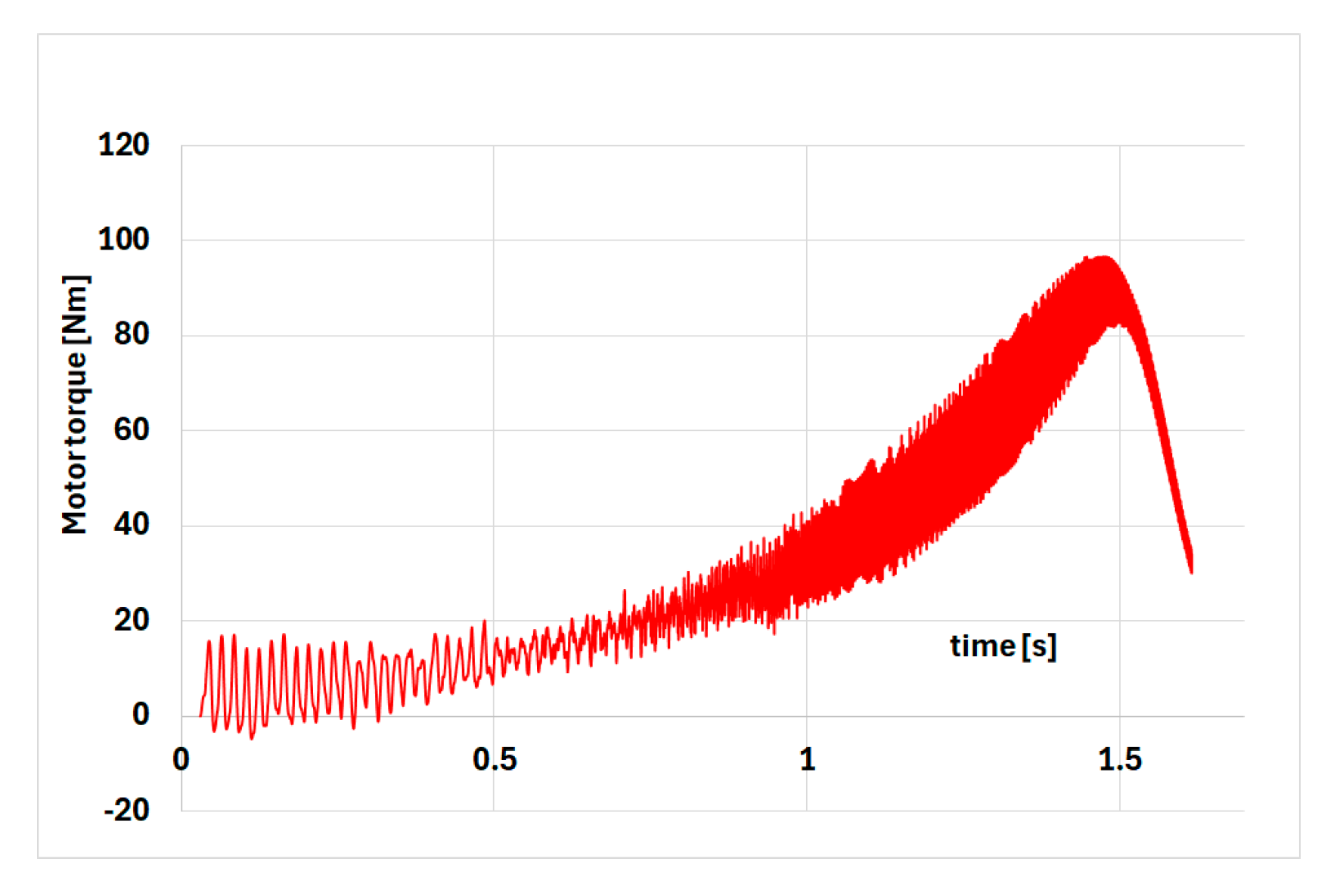
Figure 9.
Simulated waveform of the electromagnetic torque generated by the motor.
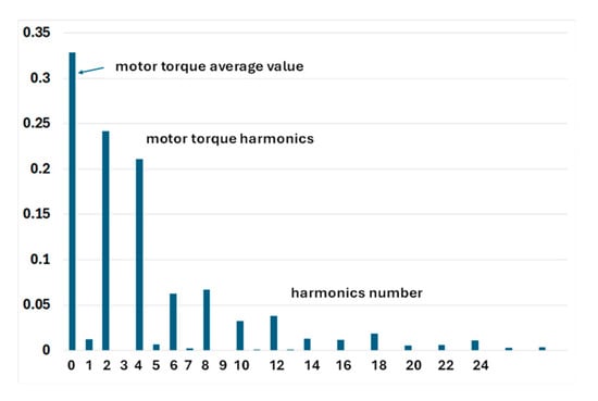
As can be seen from Figure 9, the time course of the torque is significantly distorted. Therefore, Figure 10 shows its distribution into harmonics, taking into account the average value that creates the useful average torque.
Figure 10.
Harmonic components of the electromagnetic torque.
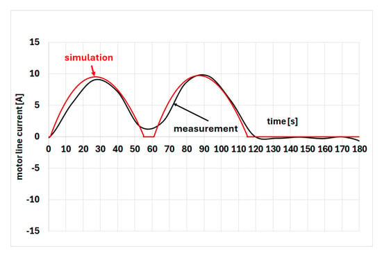
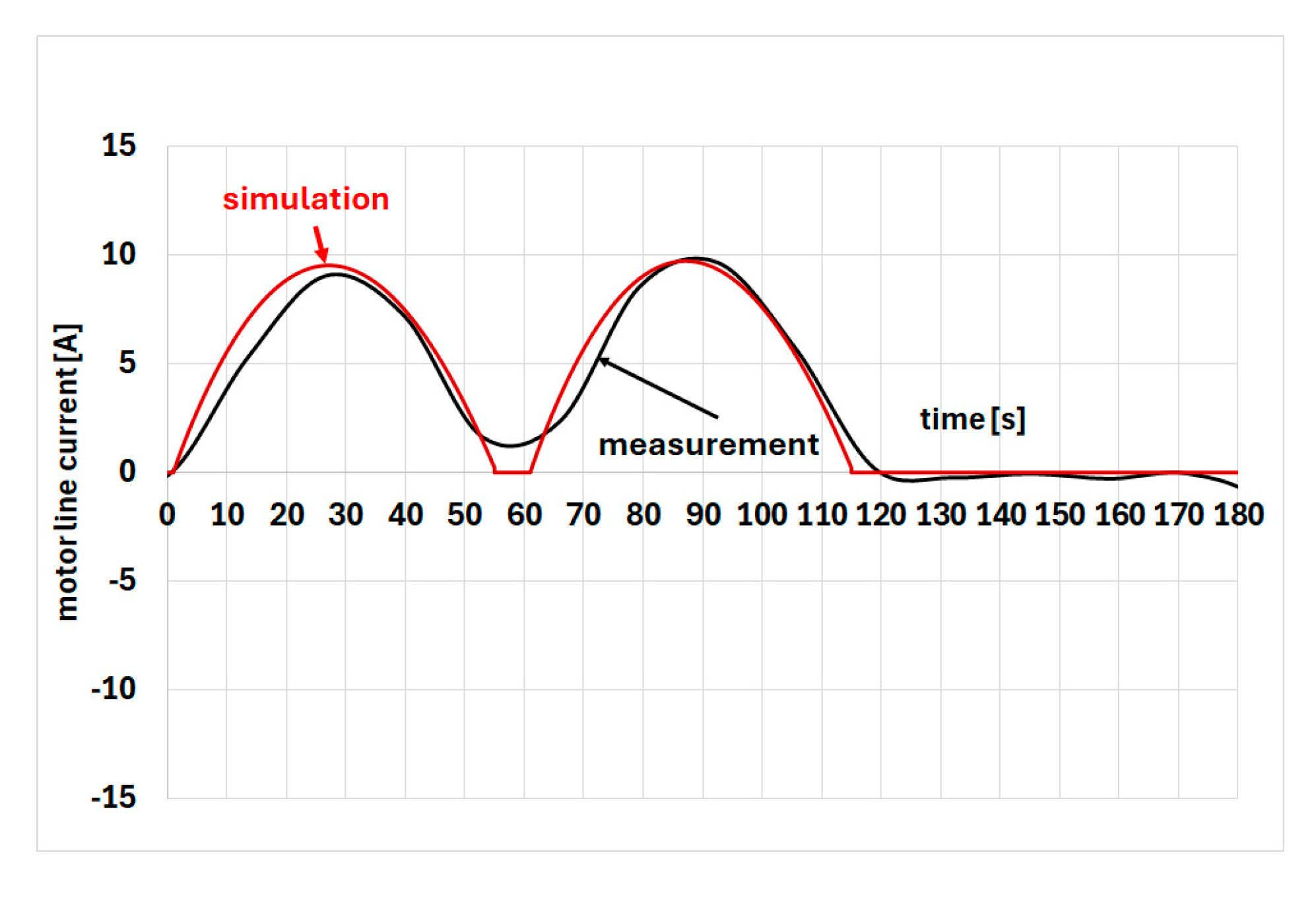
As shown in Figure 10, the higher torque harmonics are significant, causing vibration and additional stress on the clutch between the drive and the load. Similarly, Figure 11 shows the current drawn by the motor from the mains. Simulated and measured values were compared, demonstrating good agreement.
Figure 11.
Motor line current waveform over time.
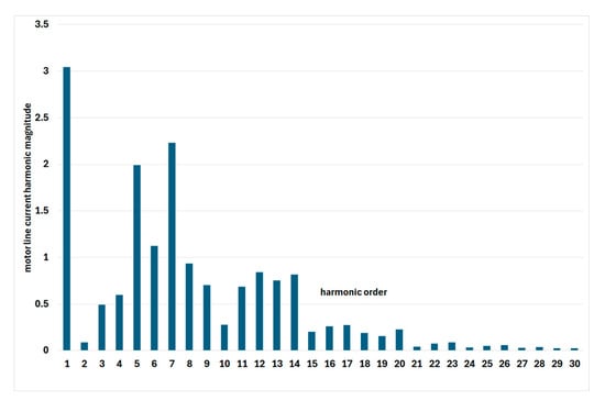
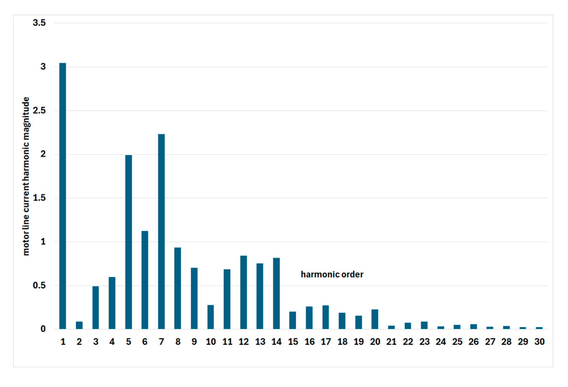
Similarly to the electromagnetic torque, the phase current and line current shown in the figure are significantly distorted. This is evidenced by the harmonic distribution shown in Figure 12.
Figure 12.
Distribution of motor line current into harmonics.
As shown in Figure 12, the contribution of higher harmonics (5th, 7th, 11th, and 14th) is significant, and the THD factor of 1.27 is very high. As can be seen, the soft-start system limits the effective current during the start-up period, which, with direct-on-line starting, can reach several to a dozen times the rated current. A drawback of the system is significant current distortion, which occurs primarily at the beginning of the start-up process.
4. Analytical Calculation Results
Analytical calculations of the time courses of the current in the stator winding and the rotational speed were performed in the author’s DYNF program. This program enables calculations to be performed when the motor is switched on at full network voltage, as well as during soft-start, at various times, including during voltage rise with different initial values U0, and during frequency start-up.
4.1. Mathematical Model for Calculating the Dynamic States of an Induction Motor
The mathematical model of an induction motor [34] after transforming to a rectangular (x,y,0) coordinate system rotating in space with ωk speed has the form [45]
where the vectors of voltages, currents and the associated magnetic flux have the form
whereas magnetic flux
where
ωk—speed of the coordinate system, which in the (x,y,0) system is equal to the synchronous speed ωs;
ω—electrical angular speed of the rotor;
[R]—square, diagonal matrix of winding resistance;
[L]—square matrix of windings inductance;
p—number of pole pairs;
J—rotor moment of inertia;
Me—electromagnetic torque;
Mm—mechanical torque.
This model can be represented in the complex plane, which coincides with the machine’s cross-section. In this case, the axes of the rectangular coordinate system (x,y) coincide with the real axis Re and the imaginary axis Im, and the mathematical model of the induction motor takes the form [34]
where the vectors of voltages and currents have the form
The individual components of the current and voltage vectors are complex numbers:
[1] = diag (1,1,1,1)—unit matrix;
[K] = diag (0,1,1,1);
Lm—magnetizing inductance.
This model accounts for the current-skin effect in a rotor bar of any shape by reducing the bar to three equivalent circuits and for the saturation of the motor’s magnetic circuit. It allows for the calculation of dynamic waveforms of currents, electromagnetic torque, and rotational speed for any motor operating state (starting, coasting, reconnecting, voltage fluctuations and short circuits at the motor terminals, pole pair switching, motor reversal, and braking) when powered from the mains, from a soft starter, or from an inverter, and for various machine loads. When starting the motor from a soft starter, a linear increase in voltage from U0 to Un over a given time is assumed. However, any characteristic of the effective voltage U(t) can also be entered.
4.2. Calculation Results of Starting Waveforms at Unloaded Motor
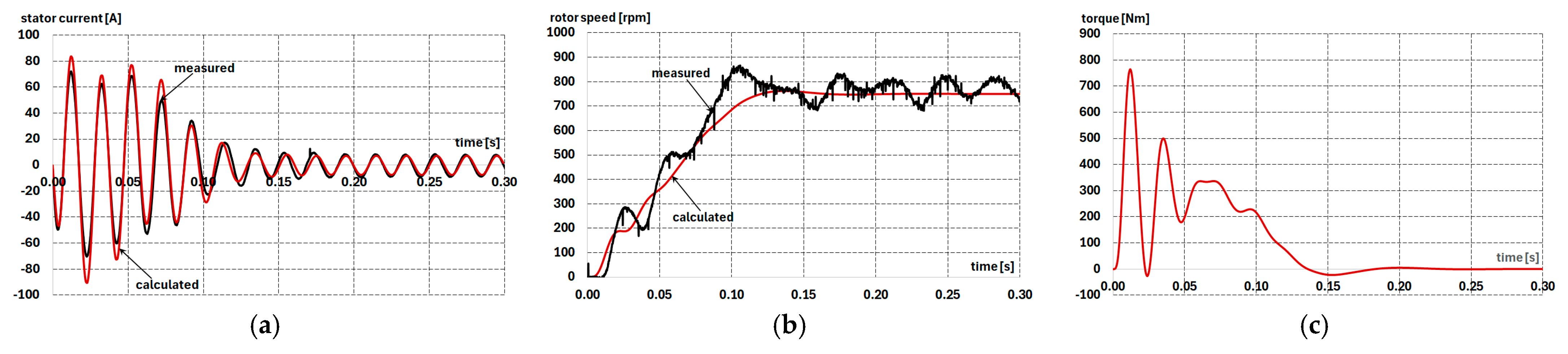
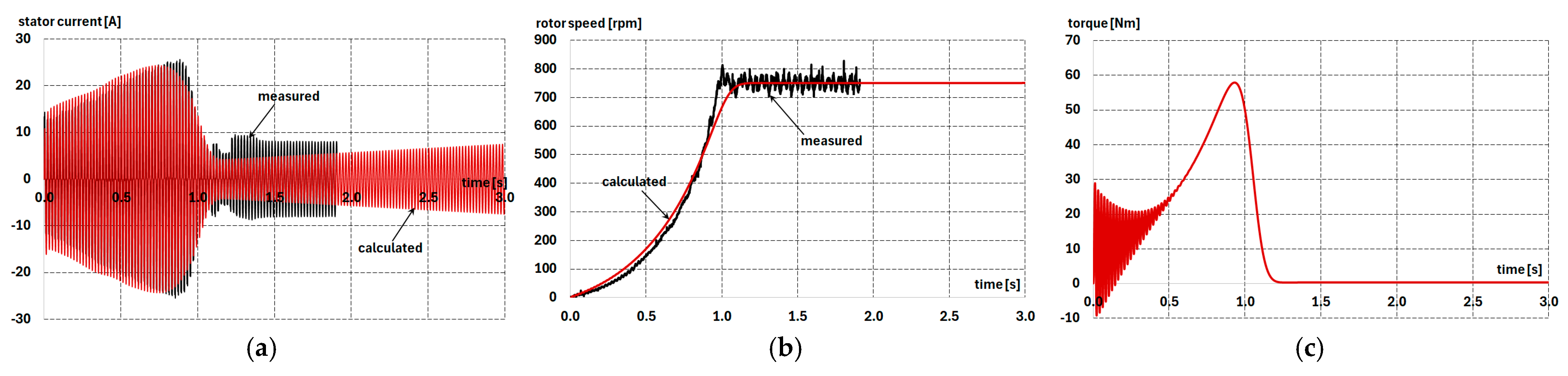
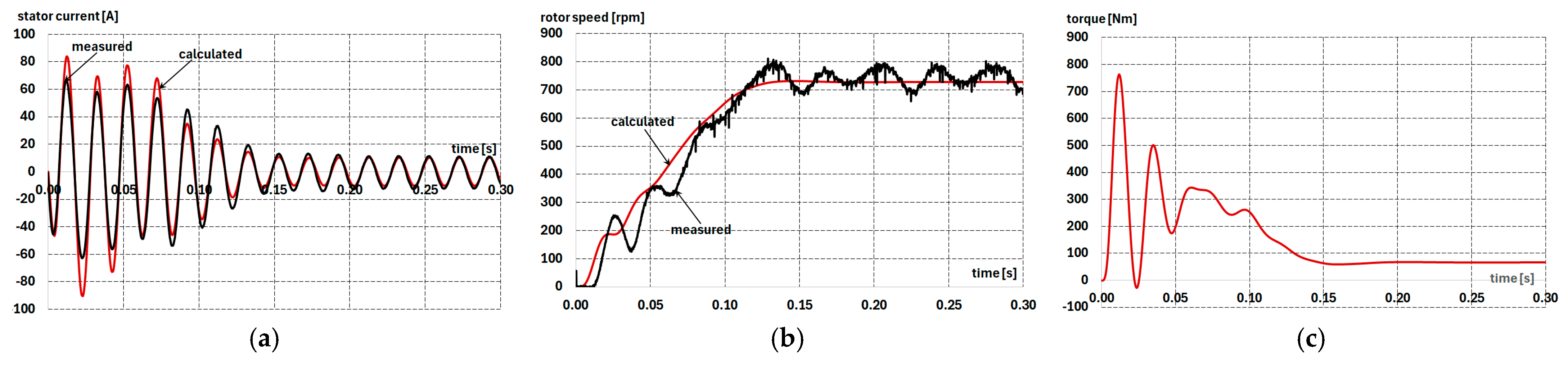
Figure 13 shows the calculated waveforms of the stator phase current, electromagnetic torque, and rotational speed during the start-up of the motor coupled to an unloaded generator, supplied with full mains voltage (Un).
Figure 13.
Measured (black line) and calculated (red line) phase current (a), engine speed (b) and torque (c) waveform in induction motor; the generator no-load state; U0 = UN.
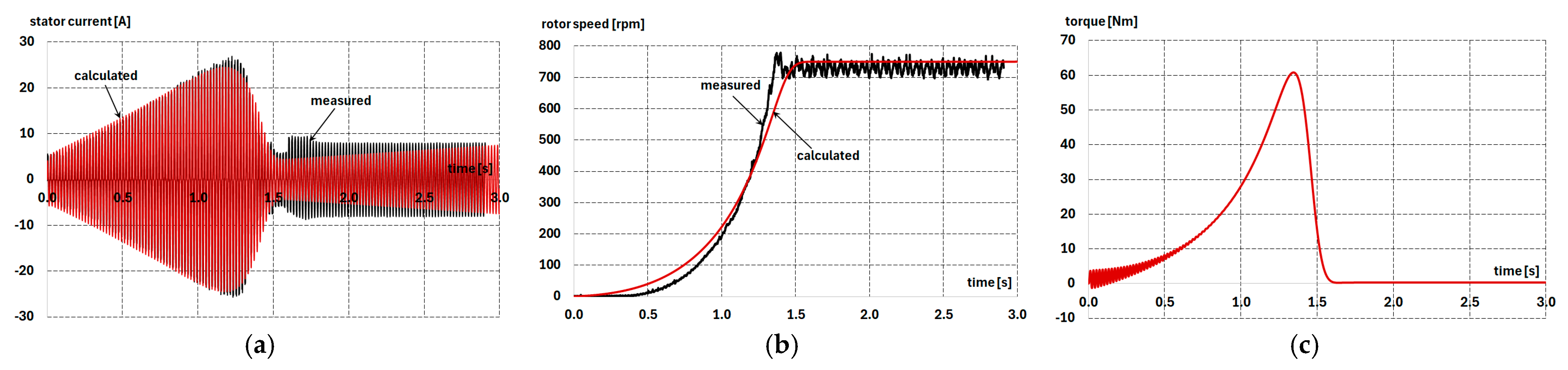
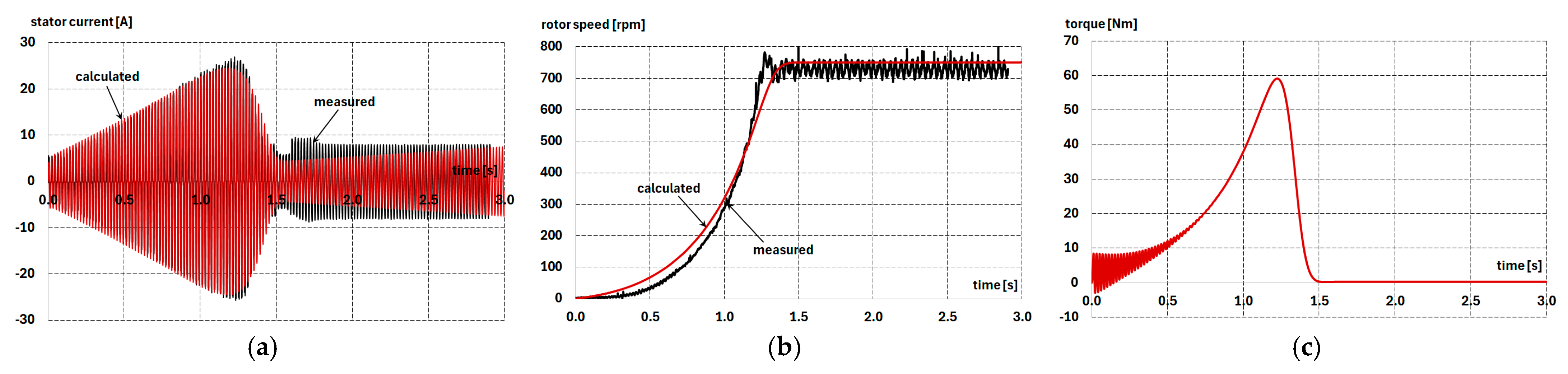
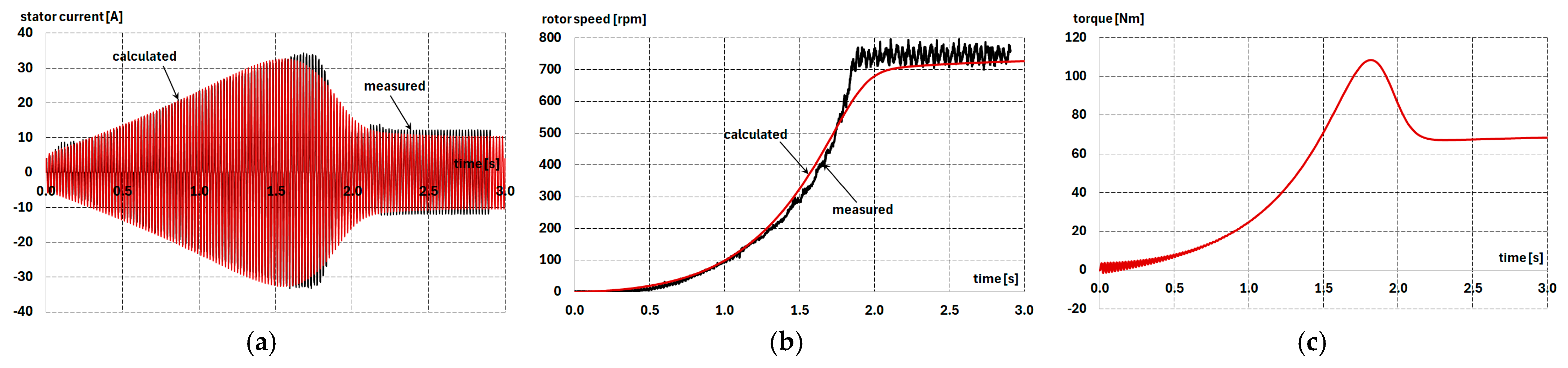
Example results of the calculations for the current course and rotational speed when starting the motor coupled to an unloaded generator, with soft-start, for different initial values of the supply voltage, a voltage rise time of 3 s, are shown in Figure 14, Figure 15, Figure 16 and Figure 17. In these figures, the calculation results are compared with the measurement results.
Figure 14.
Measured (black line) and calculated (red line) phase current (a), engine speed (b) and torque (c) waveform in induction motor; the generator no-load state; U0 = 20% UN.
Figure 15.
Measured (black line) and calculated (red line) phase current (a), engine speed (b) and torque (c) waveform in induction motor; the generator no-load state; U0 = 30% UN.
Figure 16.
Measured (black line) and calculated (red line) phase current (a), engine speed (b) and torque (c) waveform in induction motor; the generator no-load state; U0 = 40% UN.
Figure 17.
Measured (black line) and calculated (red line) phase current (a), engine speed (b) and torque (c) waveform in induction motor; the generator no-load state; U0 = 50% UN.
As shown in Figure 14, Figure 15, Figure 16 and Figure 17, increasing the initial voltage when supplying the motor with a soft starter has a negligible effect on the maximum stator current amplitude and the maximum electromagnetic torque. Still, it slightly shortens the starting time, which is related to the increase in the initial values of the electromagnetic torque.
4.3. Calculation Results of Starting Waveforms Under Motor Load
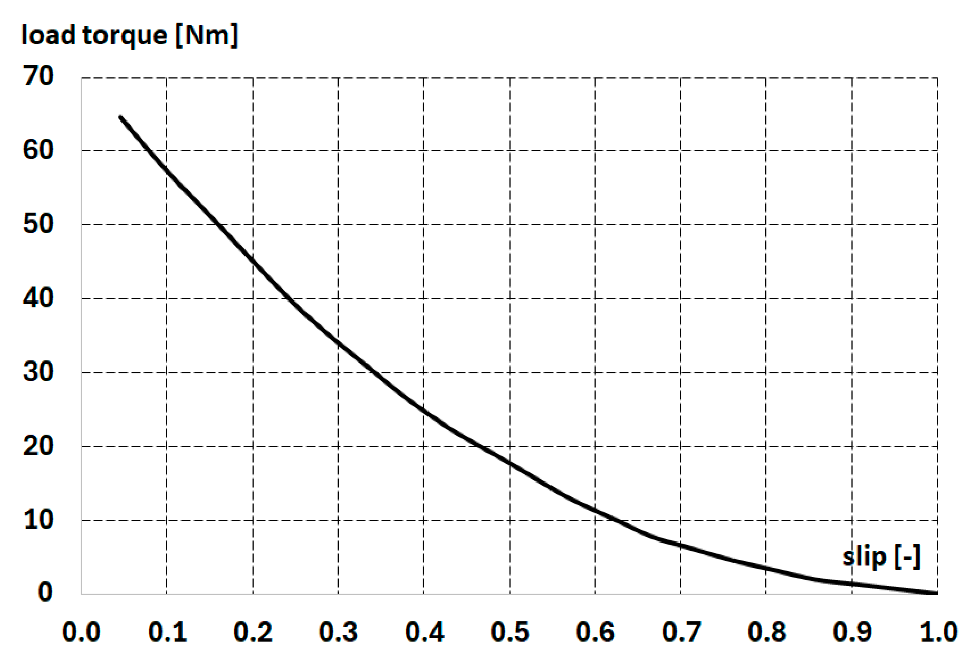
The motor’s dynamic waveforms were also determined when the generator was loaded with a resistive load. The load torque versus slip characteristic for the motor shaft is shown in Figure 18. As can be seen, this is a fan-type torque with a negligible initial value.
Figure 18.
Load torque characteristic as a function of rotor slip.
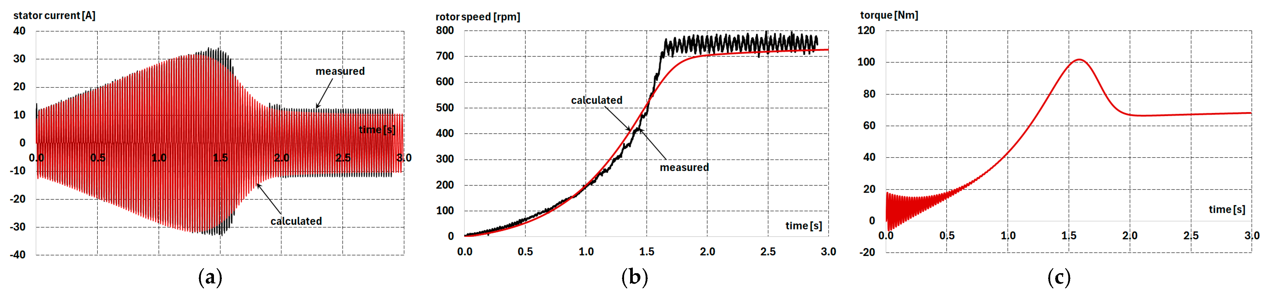
Figure 19 shows the calculated waveforms of the stator phase current, electromagnetic torque, and rotational speed during the start-up of the motor, which is coupled to a loaded generator and supplied with full mains voltage.
Figure 19.
Measured (black line) and calculated (red line) phase current (a), motor speed (b) and torque (c) waveform in induction motor; the generator load state; U0 = UN.
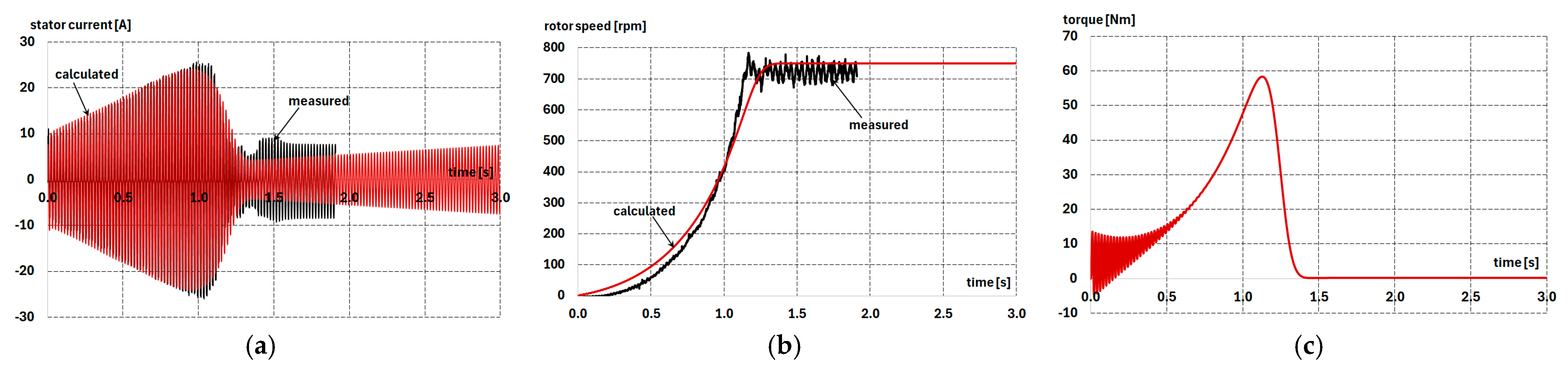
Example results of the calculations for the current course and rotational speed when starting the motor coupled to a loaded generator during soft-start initiation with different initial values of the supply voltage, and a voltage rise time of 3 s, are shown in Figure 20 and Figure 21. The calculation results are compared with the measurement results.
Figure 20.
Measured (black line) and calculated (red line) phase current (a), engine speed (b) and torque (c) waveform in induction motor; the generator load state; U0 = 20% UN.
Figure 21.
Measured (black line) and calculated (red line) phase current (a), engine speed (b) and torque (c) waveform in induction motor; the generator load state; U0 = 50% UN.
5. Optimization of Voltage Control from the Point of View of Limiting the Maximum Values of Current and Electromagnetic Torque
The selection of the initial voltage and its rise time significantly affects the maximum current and electromagnetic torque, as well as the motor starting time. The selection of these values should be correlated with the drive system requirements, taking into account the expected motor load conditions. Based on the calculations presented in the previous sections, which showed good agreement between simulation and test results, guidelines can be developed for selecting both the initial soft-start voltage and its rise time.
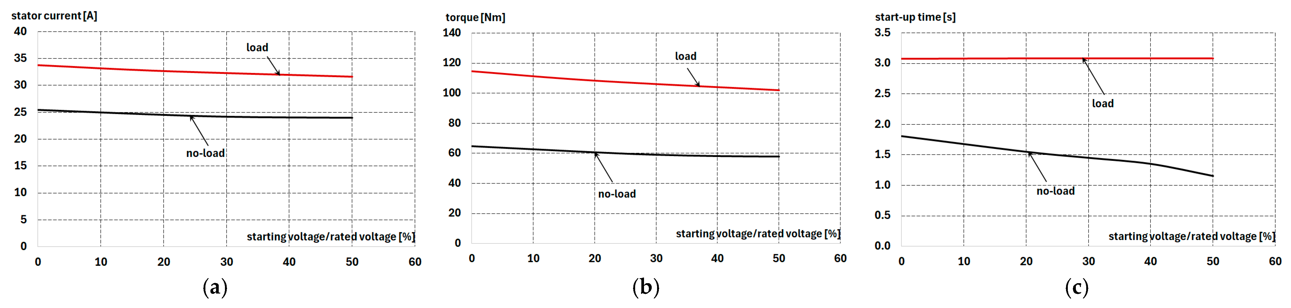
Figure 22 presents curves of the maximum stator current, electromagnetic torque, and starting time as functions of the percentage ratio of the initial soft-start voltage to the rated voltage for a motor coupled to an unloaded and loaded generator, with a constant voltage rise time of 3 s.
Figure 22.
Calculated maximal value phase current (a), torque (b) and start-up time (c) waveform in the induction motor for generator in no-load and load state; voltage rise time = 3 s.
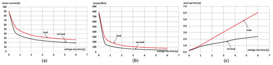
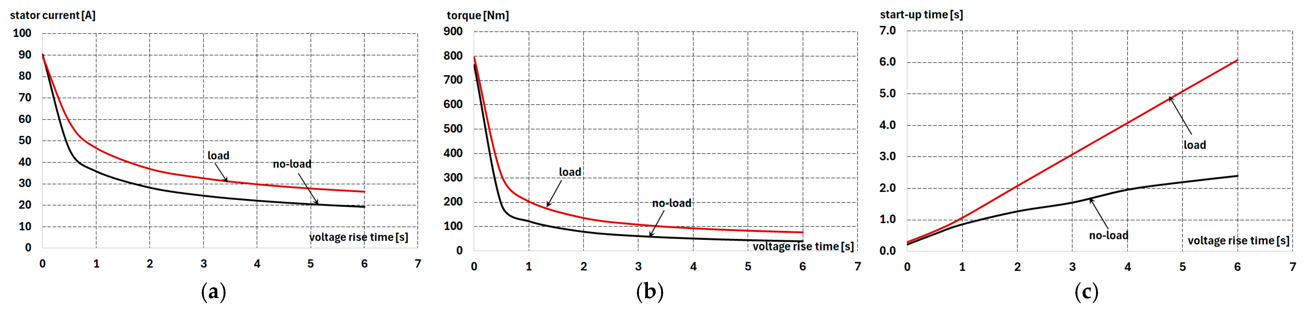
Figure 23 shows the curves of the maximum values of the stator current, electromagnetic torque, and starting time as functions of the voltage rise time from the soft start for the motor coupled to an unloaded and a loaded generator at a constant initial voltage, U0 = 20% UN.
Figure 23.
Calculated maximal value phase current (a), torque (b) and start-up time (c) waveform in the induction motor for generator in no-load and load state; starting voltage/rated voltage = 20%.
Based on the waveforms shown in Figure 22 and Figure 23, it can be concluded that the initial value of the motor supply voltage has a relatively small effect on the maximum current, electromagnetic torque, and starting time. Still, these values are strongly dependent on the voltage rise time, particularly at short rise times (less than 3 s). However, the voltage rise time significantly affects the motor start time, particularly under torque load. For example, for the tested motor, the maximum starting current should not exceed Is max = 5.8 × 16.6 = 96.3 A, while the maximum starting torque should not exceed Ms max = 2.7 × 102 = 275.4 Nm. As can be seen from the graph in Figure 23, current surges, even in direct starting, do not exceed the permissible values, while in the case of electromagnetic torque, the use of a voltage rise time of 1 s (which corresponds to a very short starting time) at a given motor load ensures that the permissible starting torque value is not exceeded.
6. Conclusions
Optimizing the operation of a soft-start system can be achieved using two approaches: applying an automatic control system, as presented, for example, in [12,16], or using a simple system that assumes a linear voltage increase from a specific initial value at an appropriately selected time. The first approach requires an extensive transducer system capable of measuring voltage and current values. The second requires the ability to simulate the drive system so that the optimal variant can be selected for a given system based on maximum and minimum torque values, maximum current, and optimal starting time. In the presented work, the second approach employed accurate simulation methods to select the optimal control variant. Calculations of individual variants can be performed with sufficient accuracy in a short time using the analytical model presented in this paper, yielding waveforms analogous to those shown in Figure 22 and Figure 23, thereby enabling the selection of optimal voltage control parameters for any motor under any load conditions. Correlating these values is a new contribution to existing research. This model accounts for nonlinear phenomena in the motor but also assumes a sinusoidal supply voltage waveform, thereby ignoring distortions in the current and starting torque waveforms caused by higher harmonics generated by the soft starter.
Using the field-circuit method, on the other hand, allows for the impact of control on the shape of the starting current to be accounted for. The starting current is highly distorted and contains significantly higher harmonics, which can increase mains voltage distortion, cause additional power losses, heat network devices, and disrupt the operation of electronic devices. A disadvantage of the field-circuit method is its high computational cost, compounded by the need to significantly reduce the time step to model the switches representing the transistors.
The simulation methods also allow for the testing of more complex control methods and algorithms.
Author Contributions
Conceptualization, M.D., K.M. and K.K.; methodology, M.D., K.K.; software, M.D., K.K.; validation, M.D., K.M. and K.K.; formal analysis, M.D., K.K.; investigation, M.D., K.K.; resources, M.D., K.M. and K.K.; data curation, M.D., K.M. and K.K.; writing—original draft preparation, M.D., K.K.; writing—review and editing, M.D., K.K.; visualization, M.D., K.K.; supervision, M.D., K.K.; project administration, M.D., K.K. All authors have read and agreed to the published version of the manuscript.
Funding
This research received no external funding.
Data Availability Statement
The data presented in this study are available on request from the corresponding author. The data are not publicly available due to machine manufacturer access restrictions.
Conflicts of Interest
The authors declare no conflicts of interest.
References
- Yang, C.; Bin Lee, S.; Jang, G.; Kim, S.; Jung, G.; Lee, J.; Shim, S.; Lim, Y.K.; Kim, J.; Park, S. Starting Current Analysis in Medium Voltage Induction Motors: Detecting Rotor Faults and Reactor Starting Defects. IEEE Ind. Appl. Mag. 2019, 25, 69–79. [Google Scholar] [CrossRef] [Scilit]
- Falahi, M.; Butler-Purry, K.L.; Ehsani, M. Induction Motor Starting in Islanded Microgrids. IEEE Trans. Smart Grid 2013, 4, 1323–1331. [Google Scholar] [CrossRef] [Scilit]
- Hu, Y.; Chen, Z.; Chen, Z.; Yuan, Y. A novel method for the analysis of the impact of the high-power motor starting on grid. In Proceedings of the 2011 4th International Conference on Electric Utility Deregulation and Restructuring and Power Technologies (DRPT), Weihai, China, 6–9 July 2011; pp. 394–398. [Google Scholar]
- Dadabaev, S. Study of voltage dips in electrical line at startup mode of powerful asynchronous motors. Energy Syst. 2020, 5, 102. [Google Scholar] [CrossRef] [Scilit]
- Ghadimi, M.; Ramezani, A.; Mohammadimehro, M. Soft Starter Modeling for an Induction Drive Starting Study in an Industrial Plant. In Proceedings of the 2011 UKSim 5th European Symposium on Computer Modeling and Simulation, Madrid, Spain, 16–18 November 2011; pp. 245–250. [Google Scholar] [CrossRef] [Scilit]
- McElveen, R.F.; Toney, M.K. Starting high-inertia loads. IEEE Trans. Ind. Appl. 2001, 37, 137–144. [Google Scholar] [CrossRef] [Scilit]
- Wang, Y.; Yin, K.; Yuan, Y.; Chen, J. Current-Limiting Soft Starting Method for a High-Voltage and High-Power Motor. Energies 2019, 12, 3068. [Google Scholar] [CrossRef] [Scilit]
- Zhang, Q.; Tong, J.; Lu, Y.; Liu, B. A simple asynchronous motor soft start method and its application. In Proceedings of the 2017 32nd Youth Academic Annual Conference of Chinese Association of Automation (YAC), Hefei, China, 19–21 May 2017; pp. 1074–1078. [Google Scholar]
- Cao, J.; Jia, G.; Zhang, C. The design soft starter of large asynchronous motor based on intelligent magnetically control. In Proceedings of the 2010 International Conference on Intelligent Control and Information Processing, Dalian, China, 13–15 August 2010; pp. 353–356. [Google Scholar] [CrossRef] [Scilit]
- Nannen, H.; Zatocil, H.; Griepentrog, G. Sensorless Soft Starter Torque and Flux Control Algorithm for Induction Motors. IEEE Trans. Ind. Electron. 2025, 72, 1230–1237. [Google Scholar] [CrossRef] [Scilit]
- Simms, S.R.; Braga, G.T.; Farr, T.A. Novel Voltage Observer for Reduced Voltage Soft-Starter Torque Ramp: Description and Analysis Results. IEEE Ind. Appl. Mag. 2023, 29, 24–32. [Google Scholar] [CrossRef] [Scilit]
- Abdel Menaem, A.; Elgamal, M.; Abdel-Aty, A.-H.; Mahmoud, E.E.; Chen, Z.; Hassan, M.A. A Proposed ANN-Based Acceleration Control Scheme for Soft Starting Induction Motor. IEEE Access 2021, 9, 4253–4265. [Google Scholar] [CrossRef] [Scilit]
- Yang, D.-Y.; Kim, Y.-S.; Oh, T.-H.; Lee, S.-H.; Cho, D.-I. Closed-Loop Soft Starter Firing Angle Control Method Using Only Current Feedback. IEEE Access 2024, 12, 112062–112073. [Google Scholar] [CrossRef] [Scilit]
- Yang, D.-Y.; Kim, T.-H.; Oh, T.-H.; Kim, Y.-S.; Lee, S.-H.; Cho, D.-I.D. A Current Balancing Method of Two-Phase Soft Starter for Three-Phase Induction Motor Drive System Without Current Sensor. In Proceedings of the 2022 13th Asian Control Conference (ASCC), Jeju Island, Republic of Korea, 4–7 May 2022; pp. 1309–1314. [Google Scholar]
- Kosykh, V.; Udovichenko, A.; Lopatkin, N.; Zinoviev, G.; Grishanov, E.; Sarakhanova, R. Analysis of the Control System for a Soft Starter of an Induction Motor Based on a Multi-Zone AC Voltage Converter. Electronics 2022, 12, 56. [Google Scholar] [CrossRef] [Scilit]
- Dhar, S.; Islam, S. Fuzzy Logic-based Soft Starter for Controlling Starting Parameters of Induction Motor. In Proceedings of the 2023 International Conference on Electrical, Computer and Communication Engineering (ECCE), Chittagong, Bangladesh, 23–25 February 2023; pp. 1–6. [Google Scholar]
- Deraz, S.A.; Azazi, H.Z. Current limiting soft starter for three phase induction motor drive system using PWM AC chopper. IET Power Electron. 2017, 10, 1298–1306. [Google Scholar] [CrossRef] [Scilit]
- Li, S.; Liu, Z. A New Method of Constant-Current Soft Starting of Induction Motor Based on Fuzzy Control. In Proceedings of the 2009 First International Workshop on Education Technology and Computer Science, Wuhan, China, 7–8 March 2009; pp. 1064–1067. [Google Scholar] [CrossRef] [Scilit]
- Shabestari, P.M.; Mehrizi-Sani, A. Current Limiting and Torque Pulsation Reduction of the Induction Motors. In Proceedings of the 2019 IEEE Power & Energy Society General Meeting (PESGM), Atlanta, GA, USA, 4–8 August 2019; pp. 1–5. [Google Scholar] [CrossRef] [Scilit]
- Zenginobuz, G.; Cadirci, I.; Ermis, M.; Barlak, C. Performance optimization of induction motors during Voltage-controlled soft starting. IEEE Trans. Energy Convers. 2004, 19, 278–288. [Google Scholar] [CrossRef]
- Solveson, M.G.; Mirafzal, B.; Demerdash, N.A.O. Soft-started induction motor modeling and heating issues for different starting profiles using a flux linkage ABC frame of reference. IEEE Trans. Ind. Appl. 2006, 42, 973–982. [Google Scholar] [CrossRef] [Scilit]
- Nied, A.; Oliveira, J.; Farias Campos, R.; Dias, R.P.; Souza Marques, L.C. Soft Starting of Induction Motor with Torque Control. IEEE Trans. Ind. Appl. 2010, 46, 1002–1010. [Google Scholar] [CrossRef] [Scilit]
- Nannen, H.; Zatocil, H.; Griepentrog, G. Novel predictive start-up algorithm for soft starter driven induction motors. In Proceedings of the IECON 2020 The 46th Annual Conference of the IEEE Industrial Electronics Society (IECON), Singapore, 18–21 October 2020; pp. 3071–3078. [Google Scholar] [CrossRef] [Scilit]
- Nannen, H.; Zatocil, H.; Griepentrog, G. Predictive Firing Algorithm for Soft Starter Driven Induction Motors. IEEE Trans. Ind. Electron. 2022, 69, 12152–12161. [Google Scholar] [CrossRef] [Scilit]
- Xie, S.; Liang, R.; Liang, L.; Yang, Z.; Gao, X. One Novel Soft-Starting Control Strategy for Induction Motor Based on Space Voltage Vectors. Int. J. Adv. Netw. Monit. Control. 2022, 7, 59. [Google Scholar] [CrossRef] [Scilit]
- Guangqiang, L.; Fei, H.; Qiang, L.; Yanchao, J. Torque close-loop control of a novel soft starter of induction motor. In Proceedings of the 2013 IEEE International Symposium on Industrial Electronics, Kuching, Malaysia, 22–25 September 2013; pp. 1–6. [Google Scholar]
- Shihong, G.; Wei, G.; Chu, J.; Yu, Y. Soft starting high-voltage induction motors with the optimum performance. In Proceedings of the 2011 International Conference on Materials for Renewable Energy & Environment, Shanghai, China, 20–22 May 2011; pp. 655–659. [Google Scholar] [CrossRef] [Scilit]
- Nannen, H.; Zatocil, H.; Griepentrog, G. Industrialized Flux-Oriented Start-up Algorithm for Soft Starter Driven Induction Motors. In Proceedings of the 2021 23rd European Conference on Power Electronics and Applications (EPE’21 ECCE Europe), Ghent, Belgium, 6–10 September 2021; pp. P.1–P.10. [Google Scholar] [CrossRef] [Scilit]
- Menaem, A.; Beryozkina, S.; Safaraliev, M. Intelligent current-speed soft-starting controller for an induction motor drive system. J. Energy Syst. 2024, 8, 221–236. [Google Scholar] [CrossRef] [Scilit]
- Zenginobuz, G.; Cadirci, I.; Ermis, M.; Barlak, C. Soft starting of large induction motors at constant current with minimized starting torque pulsations. IEEE Trans. Ind. Appl. 2001, 37, 1334–1347. [Google Scholar] [CrossRef] [Scilit]
- Gritter, D.; Wang, D.; Habetler, T.G. Soft starter inside delta motor modeling and its control. In Proceedings of the Conference Record of the 2000 IEEE Industry Applications Conference, Thirty-Fifth IAS Annual Meeting and World Conference on Industrial Applications of Electrical Energy (Cat. No.00CH37129), Rome, Italy, 8–12 October 2000; Volume 2, pp. 1137–1141. [Google Scholar] [CrossRef] [Scilit]
- Jiang, Z.B.; Zhong, T.; Rao, Y.H. Simulation of Soft Start-Up of Asynchronous Machines with Pump-Control Function Based on Thyristor. In Proceedings of the 2011 International Conference of Information Technology, Computer Engineering and Management Sciences, Nanjing, China, 24–25 September 2011; pp. 131–135. [Google Scholar] [CrossRef] [Scilit]
- Staszak, J. Solid-Rotor Induction Motor Modeling Based on Circuit Model Utilizing Fractional-Order Derivatives. Energies 2022, 15, 6371. [Google Scholar] [CrossRef] [Scilit]
- Dems, M.; Komeza, K.; Szulakowski, J.; Kubiak, W. Dynamic simulation of high-speed induction motor. Energies 2021, 14, 2713. [Google Scholar] [CrossRef] [Scilit]
- Bensalem, Y.; Naceur, M. Modeling and Simulation of Induction Motor based on Finite Element Analysis. Int. J. Power Electron. Drive Syst. 2016, 7, 1100. [Google Scholar] [CrossRef] [Scilit]
- Huangfu, Y.; Wang, S.; Qiu, J.; Zhang, H.; Wang, G.; Zhu, J. Transient Performance Analysis of Induction Motor Using Field-Circuit Coupled Finite-Element Method. IEEE Trans. Magn. 2014, 50, 873–876. [Google Scholar] [CrossRef] [Scilit]
- Zaheer, M.; Lindh, P.; Aarniovuori, L.; Pyrhönen, J. Converter-Fed Induction Motor Finite Element Analysis with Different Time Steps. In Proceedings of the 2020 XI International Conference on Electrical Power Drive Systems (ICEPDS), Saint-Petersburg, Russia, 4–7 October 2020; pp. 1–7. [Google Scholar] [CrossRef] [Scilit]
- Dyck, D.N.; Gilbert, G.; Lowther, D.A. A Performance Model of an Induction Motor for Transient Simulation with a PWM Drive. IEEE Trans. Magn. 2010, 46, 3093–3096. [Google Scholar] [CrossRef] [Scilit]
- Lee, J.-J.; Nam, H.; Young-Kyon Kim, Y.-K.; Hong, J.-P.; Hwang, D.-H. Finite element analysis of 3-phase induction motor with PWM inverter. In Proceedings of the Sixth International Conference on Electrical Machines and Systems, Beijing, China, 9–11 November 2003; Volume 2, pp. 744–746. [Google Scholar]
- Skalka, M.; Ondrůšek, Č.; Schreier, L.; Michailidis, P. Torque components identification of induction machine by FEM. In Proceedings of the International Aegean Conference on Electrical Machines and Power Electronics and Electromotion, Joint Conference, Istanbul, Turkey, 8–10 September 2011; pp. 185–189. [Google Scholar] [CrossRef] [Scilit]
- Kocman, S.; Orsag, P.; Pecinka, P. Simulation of Start-Up Behaviour of Induction Motor with Direct Online Connection. Adv. Electr. Electron. Eng. 2018, 15, 754–762. [Google Scholar] [CrossRef] [Scilit]
- Yu, M.; Zhu, J.; Wang, X. Numerical analysis of finite element combined simulation model for three-phase squirrel-cage induction motor. In Proceedings of the 2017 36th Chinese Control Conference (CCC), Dalian, China, 26–28 July 2017; pp. 10214–10219. [Google Scholar] [CrossRef] [Scilit]
- Tvorić, S.; Tomičić, B.; Car, S. Calculation of asynchronous traction motor start-up characteristics by FEM method. In Proceedings of the International Symposium on Power Electronics Power Electronics, Electrical Drives, Automation and Motion, Sorrento, Italy, 19–22 June 2012; pp. 485–489. [Google Scholar] [CrossRef] [Scilit]
- Kan, C.; Jiang, T.; Jin, K.; Fang, Y.; Zhang, H. Soft-Starting Brushless Doubly Fed Machine Winding Design and Magnetic Field Analysis. IEEE Trans. Ind. Appl. 2023, 59, 1492–1499. [Google Scholar] [CrossRef] [Scilit]
- Dems, M.; Komeza, K. Modeling of Static and Dynamic Operating States of Induction Motors; Monograph of the Lodz University of Technology Publishing House: Lodz, Poland, 2011; pp. 1–332. ISBN 978-83-7283-449-2. (In Polish) [Google Scholar]

Disclaimer/Publisher’s Note: The statements, opinions and data contained in all publications are solely those of the individual author(s) and contributor(s) and not of MDPI and/or the editor(s). MDPI and/or the editor(s) disclaim responsibility for any injury to people or property resulting from any ideas, methods, instructions or products referred to in the content. |
© 2025 by the authors. Licensee MDPI, Basel, Switzerland. This article is an open access article distributed under the terms and conditions of the Creative Commons Attribution (CC BY) license.