


Abstract
Employment of a battery energy storage system to compensate for the generation-consumption mismatch is a vital element for a resilient microgrid. However, the frequent (i.e., short-term) cyclic activity and the abrupt current variations (i.e., high di/dt) have adverse effects on the energy-type battery’s lifespan. On the other hand, the power-type supercapacitor energy storage system (SCES) has almost zero lifetime degradation when it is subjected to irregular charging/discharging patterns. Therefore, the hybridization between them can reduce battery stress levels. This study proposes a droop control algorithm with multiple segments for a SCES/battery hybrid energy storage system (HESS) that is employed in a solar/wind DC microgrid. The presented control scheme is decentralized since it avoids the central controller (CC) and the communication links between the controllers of SCES and battery units. To eliminate the short-term cyclic operation of the battery, the SCES regulates the bus voltage inside a narrow zone with a droop curve that exploits all its available energy capacity. Inside this zone, the battery is kept inactive. As soon as the bus voltage deviates from this band, the SCES enters the idle mode, and the battery is triggered following a droop curve different for charging or discharging mode to stabilize the bus voltage. To evaluate the effectiveness of the proposed system over a battery-only system and a hybrid SCES/battery system controlled with the classical droop method, a comparative analysis under different scenarios is presented.
1. Introduction
Environmentally friendly renewable energy sources (RESs) such as photovoltaic units (PVs) and wind turbine generators (WTGs) are scalable and can be installed in industrial, commercial, agricultural, and residential areas [1]. Moreover, their primary sources such as solar irradiation and wind are abundant in nature. On the other hand, environmental pollution, high cost, and rapid depletion of fossil fuels are their main demerits [2]. To achieve the demanding decarbonization targets, governments worldwide are striving to replace conventional, fossil fuel-based power generation with RES-based generation [3]. Therefore, the power system’s dependability on renewables has increased, raising the concerns of both the industry and academic sectors.
This changing environment has prompted the development of new microgrid architectures that provide a framework to facilitate the integration of RESs and energy storage systems [4]. A microgrid is a group of distributed energy sources, interconnected loads, and storage systems with clearly defined electrical and geographical boundaries that acts as a single entity with respect to the grid. Additionally, it has the ability to operate both in grid-connected and islanded mode [5]. The high proliferation of DC power sources along with the emergence of modern DC loads contribute to the rapid development of DC microgrids [6]. This trend is further enhanced by their inherent advantages in relation to AC, such as the absence of harmonic pollution, phase unbalances and synchronization issues, and zero reactive power flows [7]. However, their resilient operation is jeopardized by RESs volatility, abrupt load variations, unscheduled disconnections from the utility grid, and faults that may occur on the power lines [8]. These disturbances can cause DC bus voltage fluctuations and deteriorate the overall power quality. Therefore, employment of a properly controlled energy storage system to compensate for the generation-consumption mismatch is a prominent solution to improve the microgrid’s stability and ensure its safe operation for end-users.
Energy-type lead–acid and lithium-ion electrochemical batteries are the most dominant energy storage types in microgrids due to their high-energy density, high efficiency, and relatively high level of maturity [9]. However, short-term (i.e., frequent) cyclic operation and high charging/discharging rates (i.e., high di/dt) significantly shrink their lifetime [10,11,12]. Hence, the maintenance and replacement costs are increased [13]. Additionally, their power density is limited. Thus, conventional batteries cannot handle effectively high-frequency power fluctuations. An extensive review regarding the diverse battery types can be found in [9]. On the other hand, power-type supercapacitor energy storage (SCES) systems have negligible lifetime degradation under the previous conditions and high-power density to respond instantaneously to power requirements. Nevertheless, the energy density is smaller and the capital cost is higher than those of the batteries [9]. Therefore, SCES/battery hybrid energy storage systems (HESSs) are composed of complementary storage types, exploiting their merits and concealing their demerits at the same time under a suitable control algorithm. Moreover, under the hybridization principle, the size of the battery can be significantly reduced compared to a battery-only scheme without downgrading the quality of the power system [14]. A study with particular emphasis on SCES chemistry and material design is presented in [15].
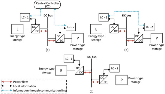
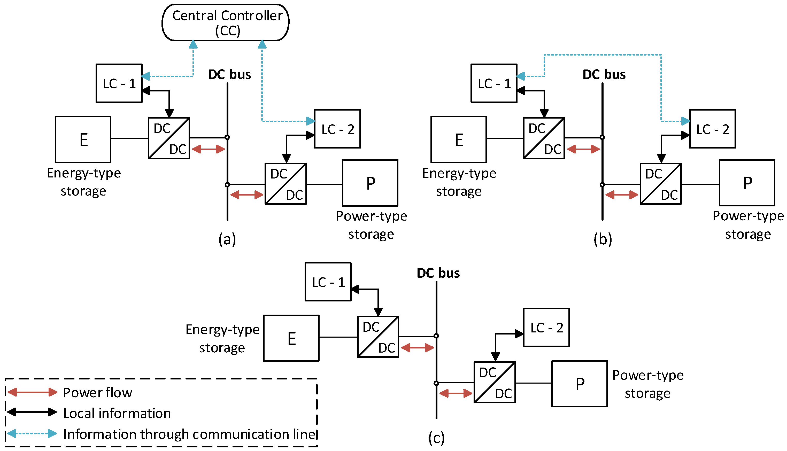
The HESSs control strategies can be mainly categorized into (i) centralized, (ii) distributed, and (iii) decentralized [16]. Their schematic diagram is illustrated in Figure 1. In centralized control, a central controller (CC) is required to adjust the local controllers (LCs) of the power and energy-type storage converters, providing strong-supervised control. The CC collects system information and transmits accordingly reference signals for the LCs through the communication infrastructure [17]. Hence, this method suffers from communication failures due to time delays during signal transfer procedures, and single points of failure. In the distributed control, there is no CC, and each LC receives local information along with data from neighboring LCs via sporadic communication links to achieve coordination between the different storage converters [18]. Thus, this method is free from single points of failure but is still prone to communication delays. Ultimately, in the decentralized strategy, the CC and the communication network are completely absent, and each LC only receives local information. Therefore, it is unaware of the status of adjacent LCs or the system status, operating independently [19].
Figure 1.
The schematic diagram of HESSs control methods: (a) Centralized; (b) distributed; (c) decentralized.
A proper technique for power allocation among power- and energy-type storage systems is indispensable for an effective HESS. In this framework, the most widely adopted power allocation scheme for the majority of HESSs, including hybrid SCES/battery systems, is the filtration-based scheme that is implemented in [10,20,21,22,23,24]. This method employs a filter to decompose the net power into low- and high-frequency components to be handled by energy and power-type storage systems, respectively. However, this centralized approach is not efficient under continuous disturbances since the energy-type battery has to compensate for the low-frequency component for every single disturbance. Therefore, its service life is reduced in such cases. In [20,22], a rate limiter is inserted at the output of the filter to ensure that the battery will not react faster than its specifications allow, while in [24], the cut-off frequency of the filter is generated with fuzzy logic control (FLC) according to the energy demand, the battery cell temperature, and the SCES SoC level. In [25], the hybridization between a superconducting magnetic energy storage (SMES) system and battery is considered under a distributed approach. Specifically, the battery operates as an energy buffer for the SMES and charges or discharges at a low rate. This method, though, leads to intense battery cyclic activity if the SMES current is around its rated value. A decentralized technique for a SMES/battery HESS is introduced in [26]. It employs two droop curves with different coefficients to prioritize the power-type device over the battery when the DC bus voltage fluctuates. Nevertheless, the battery is still active even if the disturbances are small and compensable by the power-type device.
Motivated by the above considerations, this study proposes a modified droop control algorithm for a SCES/battery HESS employed in a DC microgrid. The proposed method avoids the CC and the communication links since the controllers of the SCES and battery units work independently. The SCES regulates the DC bus voltage inside a narrow band, following a droop curve. As long as the bus voltage is inside this band, the battery is kept inactive. Therefore, its short-term activity is eliminated, while the SCES is fully exploited. As soon as the bus voltage deviates from the band, the SCES is kept inactive, and the battery is triggered following a droop curve different for charging or discharging mode to stabilize the voltage. The rest of this paper is organized as follows: in Section 2, the system description and modeling are presented, and in Section 3, the control techniques are analyzed. In Section 4, the system performance is investigated under different scenarios and previously reported methods. Finally, in Section 5, conclusions are drawn highlighting the merits of the proposed control algorithm.
2. System Description and Modeling
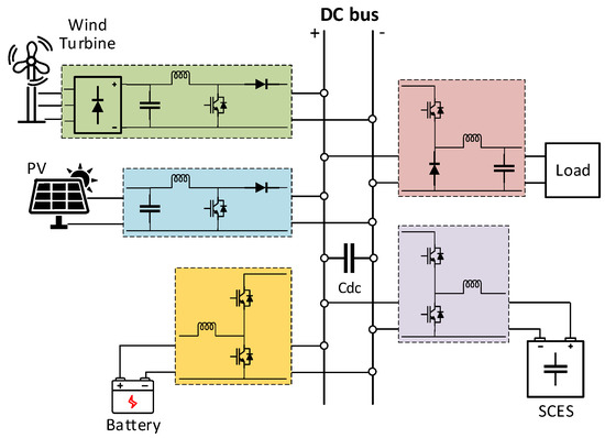
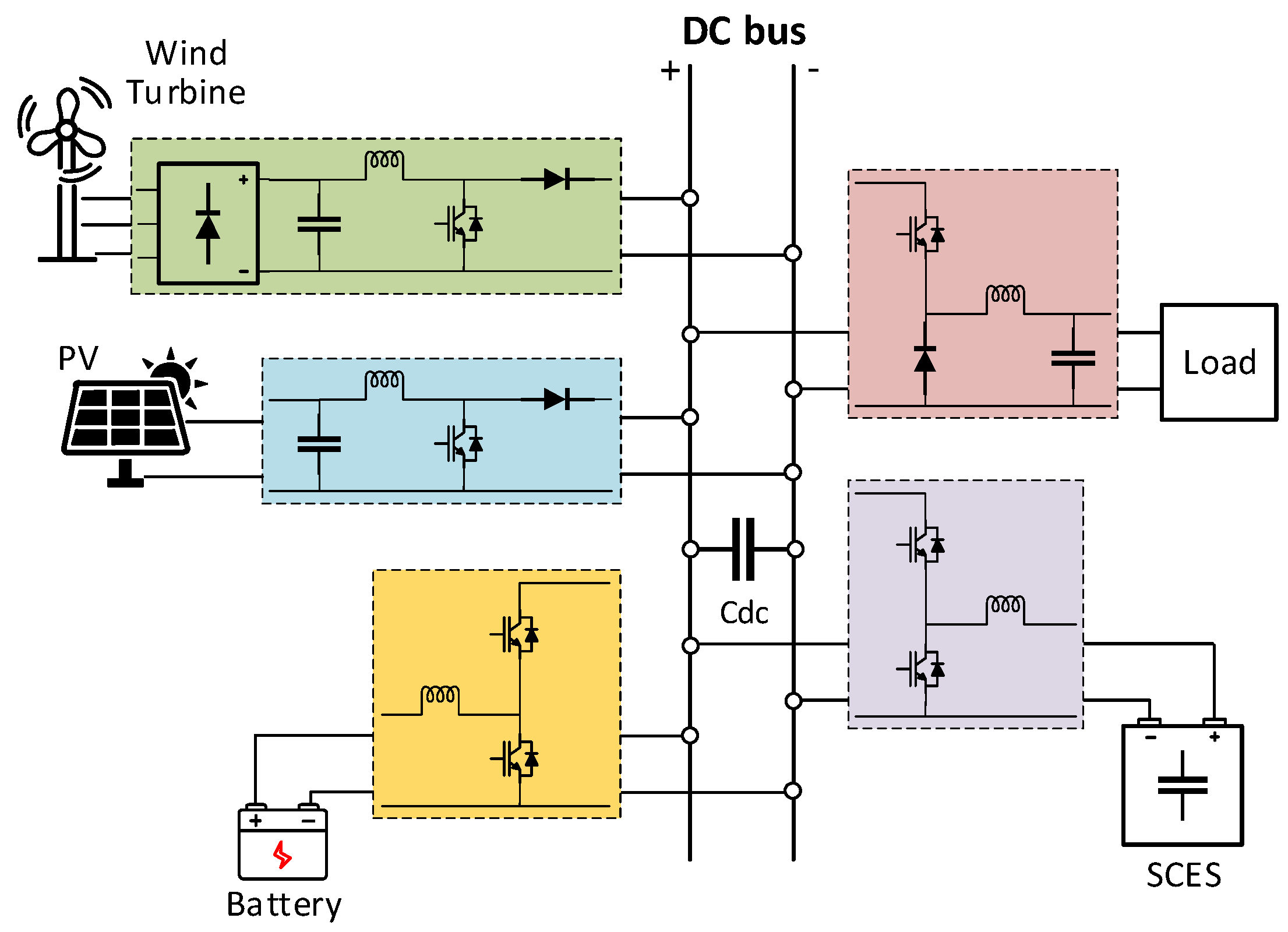
Figure 2 depicts a schematic diagram of the examined DC microgrid. It consists of a PV system, a WTG system, a resistive load, and a HESS comprised of SCES and battery units. The HESS is employed to increase the stability of the microgrid and protect the energy-type battery from quick lifetime attenuation. All microgrid components are connected through separate DC/DC converters to a common DC bus. The resistive load is fed from a buck converter, while the PV is connected to the main DC bus through a boost converter to maximize its power output. The WTG is connected to the same bus via a three-phase uncontrolled (i.e., diode-based) rectifier followed by a boost converter to extract the maximum possible wind power, as illustrated in Figure 2. The SCES and the battery employ bidirectional half-bridge converters in a parallel active topology scheme. The mathematical modeling for the system components is provided in the upcoming sections with the necessary equations.
Figure 2.
The schematic diagram of the overall system.
2.1. The Solar PV System
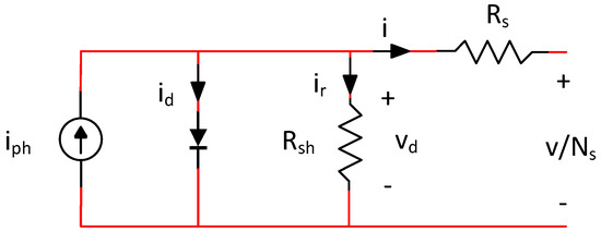
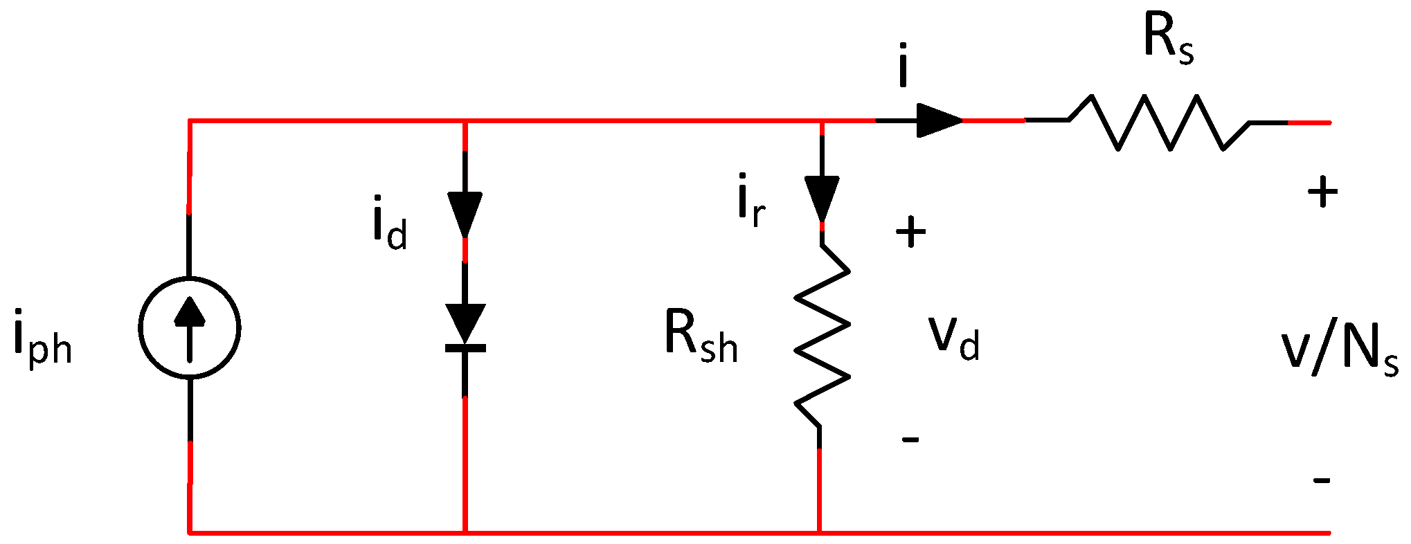
A PV panel consists of Ns solar cells in series, and Figure 3 illustrates the equivalent circuit of such a cell, while the equations that describe it are [27]:
where S0 is the sun irradiation under standard test conditions (STC) in W/m2, Tref is the temperature under STC in °C, Rs is the cell series resistance in Ohm, Rsh is the cell shunt resistance in Ohm, Isc0 is the cell short circuit current at Tref in A, Is0 is the cell diode saturation current at Tref in A, Eg is the cell band energy in eV, A is cell ideality factor, Ct is the cell temperature coefficient in A/°C or °K, ks is a coefficient that defines how solar irradiation affects cell temperature, q is the electron charge (q = 1.6 × 10⁻¹⁹ C), k is the Boltzmann constant (k = 1.3806505 × 10⁻²³), S is the actual light intensity, Ta is the actual ambient temperature, v is the voltage across the entire solar panel, and i is the current flowing out of the positive terminal of the solar panel.
Figure 3.
PV cell equivalent circuit.
The employed PV system has a rated output power of 4905 Wp and is composed of 15 SunPower SPR-E20-327 residential panels (modules) with a 327 Wp rated output power. The overall system is constructed by 3 parallel strings of 5 panels in series per string (i.e., 5S3P assembly), and its parameters are listed in Table 1.
Table 1.
The PV system parameters.
2.2. The WTG System
For wind speeds between the cut-in speed (vcin) and the rated speed (vrat), the power generated by a wind turbine can be expressed as [27]:
where A is the area of the rotor blade in m2, vwind is the wind speed in m/s, ρ is the air density (1.225 kg/m3 approximately), and Cp is the power coefficient. Cp is a function of tip speed ratio (TSR) λ and blade pitch angle β and it can be expressed as [27]:
where c1 = 0.5, c2 = 116·λ′, c3 = 0.4, c4 = 0, c5 = 5, c6 = 21·λ′, c7 = 0.01∙λ and
where ωm is the turbine rotational speed in rad/s and Rblade is the rotor blade radius in m. For wind speeds between the rated speed (vrat) and the cut-out speed (vcout), the wind turbine power is maintained near its rated value with pitch angle control.
The employed WTG system incorporates a small horizontal-axis wind turbine connected via a gearbox to a salient pole permanent magnet synchronous generator (PMSG) with sinusoidal back emf. The system specifications are listed in Table 2.
Table 2.
The WTG system parameters.
2.3. The SCES System
Supercapacitors (SCs), also named electric double-layer capacitors (EDLCs) or ultracapacitors, contain two conductor electrodes, a porous membrane separator, and an electrolyte in the areas between the electrodes and the separator. Due to their structure, supercapacitors have both the characteristics of conventional capacitors and electrochemical batteries. Usually, the energy is stored electrostatically in the form of static charge on the boundary surfaces between the electrolyte and the electrodes. The high-performance supercapacitors are based on nano materials to increase electrode surface area for enhanced capacitance [9]. SCs are classified into three main kinds: (i) EDLCs, (ii) pseudo-capacitors, and (iii) hybrid SCs [15]. EDLCs operate on the basis of electrostatic charge storage, pseudo-capacitors help in redox processes, and hybrid SCs store charge by polarizing electrodes and non-polarizing elements. The carbon-based EDLCs that contain carbon nanotubes (CNTs) and graphene have received considerable attention lately. Their structure has good mechanical, chemical, electrical, and thermal properties [9,15].
High-power density, very short response time, and negligible lifetime degradation under frequent charging/discharging cycles or abrupt power variations are the main features of the SCES. On the other hand, it has a high capital cost, low-energy density, and high self-discharge rate [28]. The mathematical model of the SCES is given by the equations:
where ESC is its stored energy in J, CSC is its capacitance in F, VSC is its voltage in V, PSC is its instantaneous power in W, ISC is its instantaneous current in A, PSC,avg is its average power in W, ISC,avg is its average current in A, SOCSC is its state of charge, and ESC,max is its maximum stored energy in J. The specifications of the small-sized SCES that is employed to eliminate the short-term cyclic activity of the battery are depicted in Table 3.
Table 3.
The SCES system parameters.
2.4. The Battery System
The dynamic battery cell model proposed in [29] is adopted in this study. This model simulates the battery cell as a controlled voltage source in series with a fixed internal resistance, and its operation is described by the equations:
Equations (16) and (17) are valid for the discharging and the charging process of the cell, respectively. Vbat is its terminal voltage in V, E0 is its constant voltage in V, K is its polarization constant in V/Ah or its polarization resistance in Ohm, Q is its maximum capacity in Ah, i is its current in A, A is its exponential zone amplitude in V, B is its exponential zone time constant inverse in (Ah)−1, R is its internal resistance in Ohm, and iLPF is its filtered current in A.
The battery pack that is employed to compensate for the long-term disturbances is composed of 3000 Molicel IHR-18650B Li-ion cells with 3.6 V nominal voltage and 2.25 Ah nominal capacity. The overall system is constructed by 30 parallel strings of 100 battery cells in series per string (i.e., 100S30P assembly). Both battery cell and battery pack technical parameters are illustrated in Table 4.
Table 4.
The battery cell and the battery pack parameters.
3. Control Techniques
3.1. The Control Method for the PV System
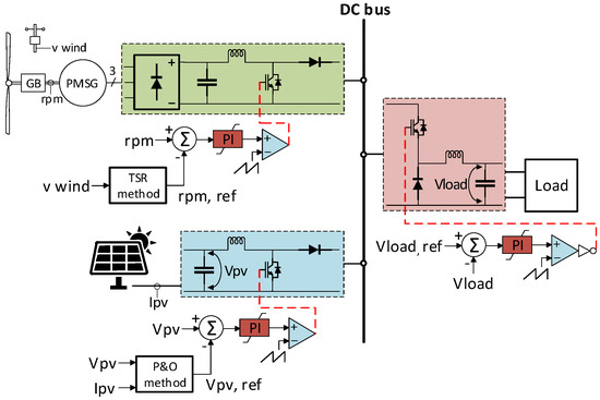
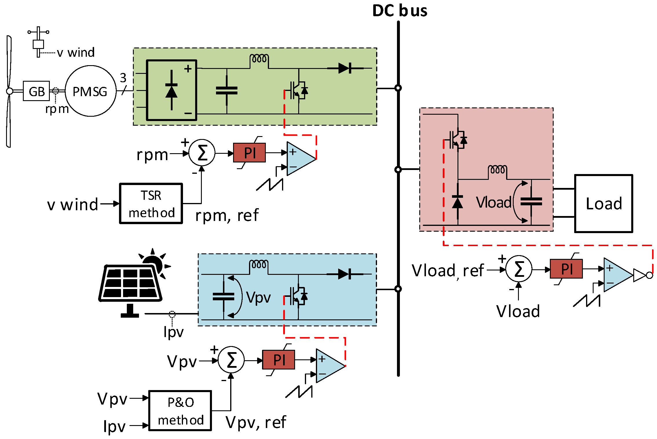
The performance of a PV panel changes with the change in solar irradiation or ambient temperature according to its characteristic curves. When irradiation increases, the maximum power point (MPP) of the PV panel is increased. Therefore, both maximum PV output power Pmpp and voltage Vmpp increase, while in the case of a temperature increase, the MPP is decreased, and consequently, both Pmpp and Vmpp decrease. Hence, to extract the maximum possible solar power, it is essential to maintain the PV panel’s terminal voltage at its MPP. This can be implemented through maximum power point tracking (MPPT) algorithms. In this study, the perturb and observe (P&O) algorithm [30,31] is implemented to calculate the reference PV terminal voltage. Afterwards, a PI controller is introduced to eliminate the voltage error and generate the desired duty cycle for the PV boost converter. Figure 4 shows the control technique employed for the PV system.
Figure 4.
The control techniques for PV, WTG, and load.
3.2. The Control Method for the WTG System
The performance of a WTG changes with the change in wind speed according to its characteristic curves. The power coefficient Cp can be maximum at only one value of TSR, λopt. During MPPT operation (β = 0), when wind speed increases, WTG speed must increase proportionally, as shown in Equation (10), to sustain λ at its optimal value. Hence, the extraction of the maximum possible wind power is realized. In this study, the TSR method [32,33] is employed, which requires TSR knowledge and wind and turbine speed measurements. Then, a PI controller is introduced to track the reference turbine speed and define the desired duty cycle for the WTG boost converter, as presented in Figure 4.
3.3. The Control Method for the Load
The resistive load is connected to the main DC bus via a buck converter that regulates the voltage across the load terminals. The error between the desired and the actual load voltage is handled by a PI controller, which generates the reference duty cycle for the load converter, as depicted in Figure 4.
3.4. The Control Method for the SCES/Battery HESS
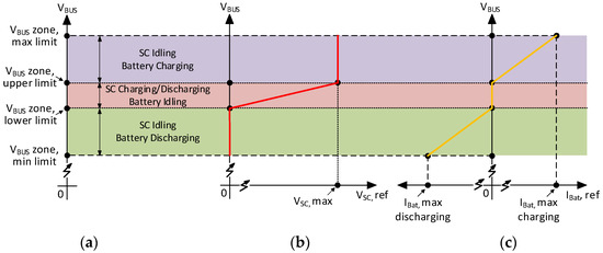
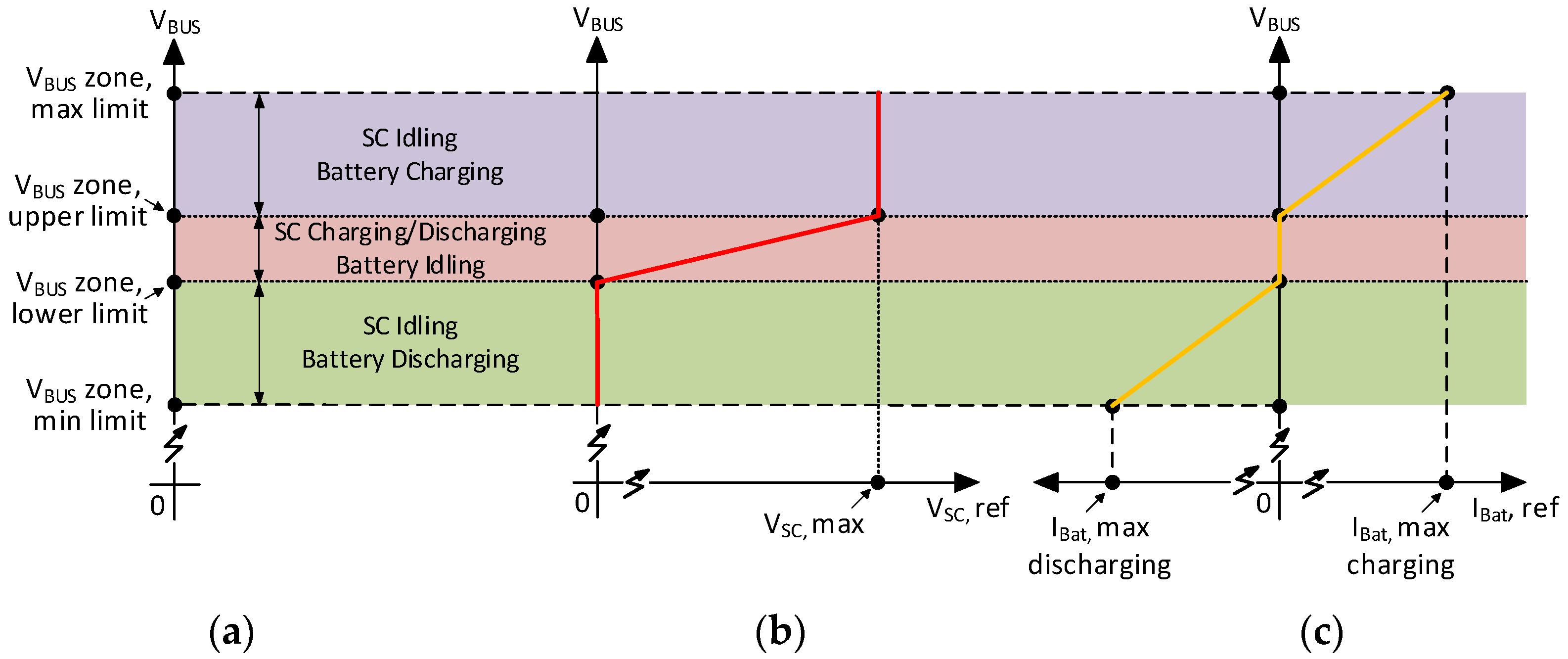
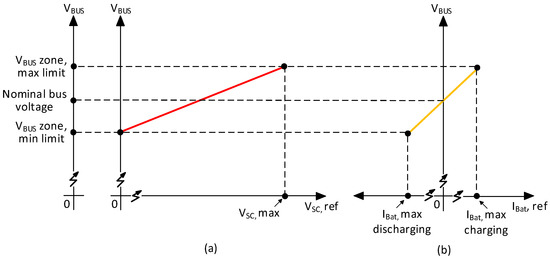
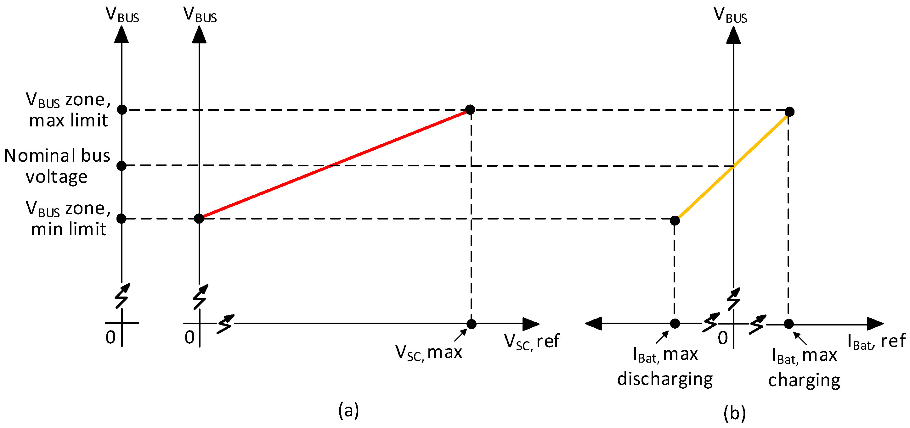
Figure 5a illustrates the working principle of the proposed control method, which is based on the DC bus voltage measurement, while Figure 5b,c depict the droop curves employed for the SCES and battery systems, respectively. As long as the DC bus voltage is inside the narrow zone defined by the VBUS zone, lower limit, and VBUS zone, upper limit, all the disturbances are compensated exclusively by the SCES, which charges or discharges accordingly, following its droop curve (Figure 5b). In such cases, the battery is kept inactive, as its reference current is zero (Figure 5c). Therefore, the frequent (i.e., short-term) cyclic operation of the battery is eliminated, and all the available energy capacity of the SCES is exploited.
Figure 5.
(a) The working principle of the proposed SCES/battery HESS control algorithm; (b) the droop curve with multiple segments for the SCES; (c) the droop curve with multiple segments for the battery.
As soon as the bus voltage drops below the VBUS zone, lower limit, the SCES enters the idling state, preserving its minimum state of charge (SoC) level. Simultaneously, the battery is triggered and follows its discharging droop curve, operating in the discharging zone of Figure 5. Once the bus voltage exceeds the VBUS zone, upper limit, the operation is derived accordingly, the SCES preserves its maximum SoC level, and the battery works in the charging zone of Figure 5. In this study, the battery discharges or charges at its maximum current, IBat, max discharging or IBat, max charging, when the minimum and maximum allowable limits for the bus voltage, VBUS zone, min limit or VBUS zone, max limit, are reached, respectively. These bus voltage limits are selected to establish a tolerance zone of ±10% on the DC bus, according to [34], while the inner voltage limits are selected to establish a much narrower zone of ±1.33% on the same bus.
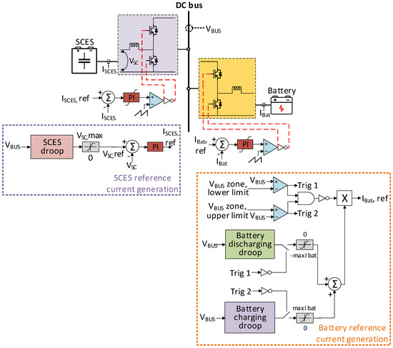
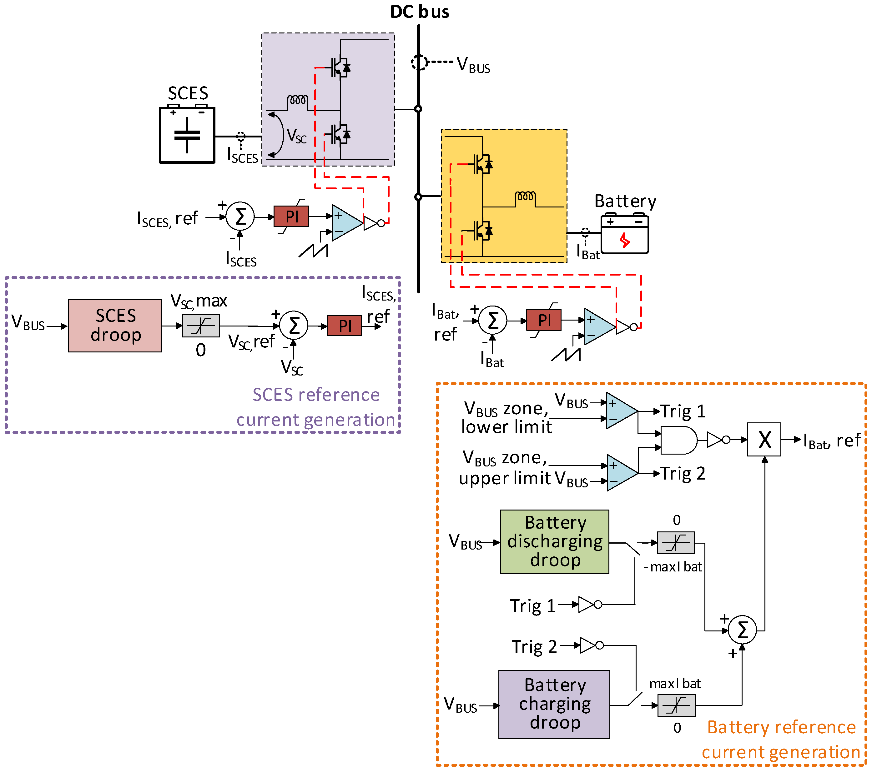
Ultimately, the proposed control method is decentralized, since it avoids the CC and the communication links between the SCES controller and the battery controller. The complete implementation of the control algorithm is depicted in Figure 6. PI controllers are employed to track the reference current signals for the SCES and the battery, defined by the corresponding reference current generation blocks. The control parameters are listed in Table 5.
Figure 6.
The complete implementation of the SCES/battery HESS control algorithm.
Table 5.
The control parameters.
3.5. The Control Method for the Battery in the Battery-Only System Used for Comparison
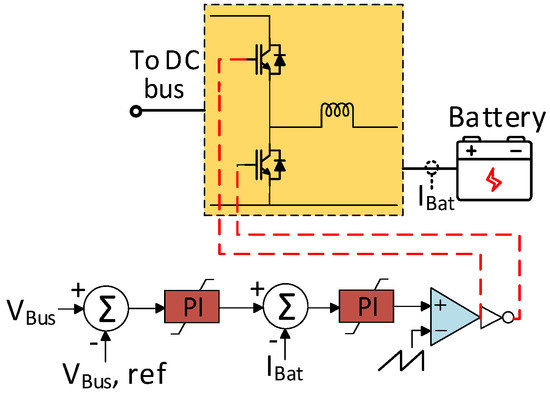
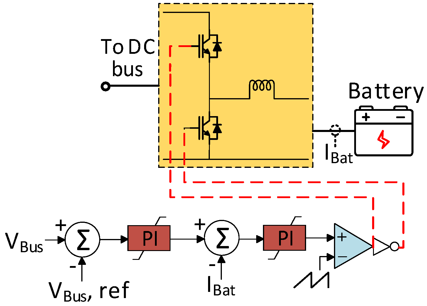
Figure 7 illustrates the control algorithm for the battery in the battery-only system (BOS) that will be used for a comparative analysis to evaluate the effectiveness of the proposed method. It consists of two cascaded PI control loops [35]. In the outer loop, the DC bus voltage reference is compared with the actual bus voltage, and the resulting error is handled by the first PI controller, which defines the battery reference current for the inner loop. Afterwards, the error in the battery current is supervised by the second PI controller, which defines the desired duty cycle for the battery converter.
Figure 7.
The control algorithm for the battery in the BOS.
3.6. The Classical Droop Control Method for the SCES/Battery HESS Used for Comparison
The working principle of the classical decentralized droop scheme that allocates the power between a fast-responsive storage system and a battery according to the DC bus voltage variations is presented in [26]. The power sharing is realized by employing two droop curves with different slopes to charge/discharge the different storage units at different rates. Their operating modes (i.e., charging, discharging, and standby) arise according to the bus voltage measurement and the corresponding droop curves, as depicted in Figure 8, employing the SCES as the fast-responsive system. Therefore, the slope of its droop curve is lower than that of the battery. Once the references for the SCES voltage and the battery current are obtained, the low-level control for the hybrid system is implemented according to Figure 6.
Figure 8.
The classical droop control for the SCES/battery HESS: (a) The droop curve with low slope for the SCES; (b) the droop curve with high slope for the battery.
4. Simulation Results and Discussion
To evaluate the effectiveness of the proposed SCES/battery HESS, its performance is investigated under different scenarios and previously reported techniques. Initially, the proposed scheme is compared with a BOS under three different scenarios according to the SCES SoC level, namely: (i) operation with an intermediate SoC level; (ii) operation with a high SoC level; and (iii) operation with a low SoC level. Therefore, an investigation is carried out in all operating regions of the proposed algorithm, and a comparative analysis is presented for each individual scenario. Afterwards, the proposed droop technique is compared with the classical droop approach for the SCES/battery HESS. The PSIM software is utilized to conduct the simulations.
4.1. Comparison with a BOS
4.1.1. Case 1: Operation with an Intermediate SCES SoC Level
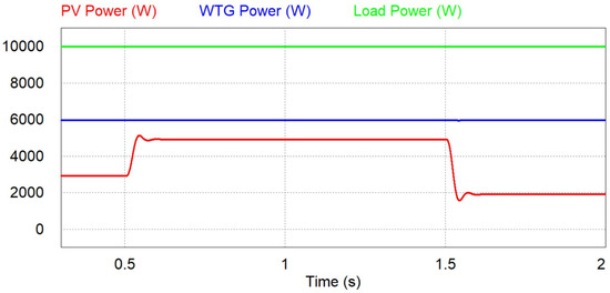
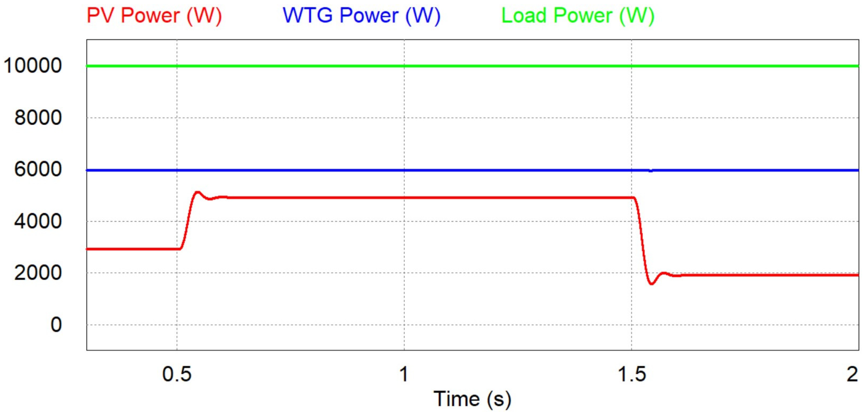
An intermediate SoC level for the SCES system is considered in this case, since its initial voltage is 200 V, along with a volatile PV generation. The duration range of the PV fluctuations is from 0.5 s up to 1 s [8]. Figure 9 indicates the power generated by the renewables and consumed by the load. The ambient temperature is fixed at 25 °C throughout the simulation, while the solar irradiation is fixed at 600 W/m2 up to 0.5 s, 1000 W/m2 from 0.5 s up to 1.5 s, and 400 W/m2 from 1.5 s up to 2 s. Consequently, the PV generates 2.93 kW, 4.93 kW, and 1.93 kW, operating at its MPP, respectively. The wind speed is constant at 12 m/s, and the WT generates 5.97 kW, extracting the maximum possible wind power, while the load demand is fixed at 10 kW.
Figure 9.
The power of PV, WTG, and load—Case 1.
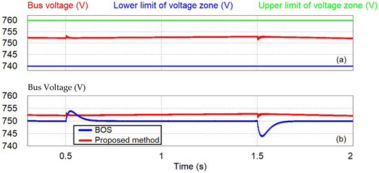
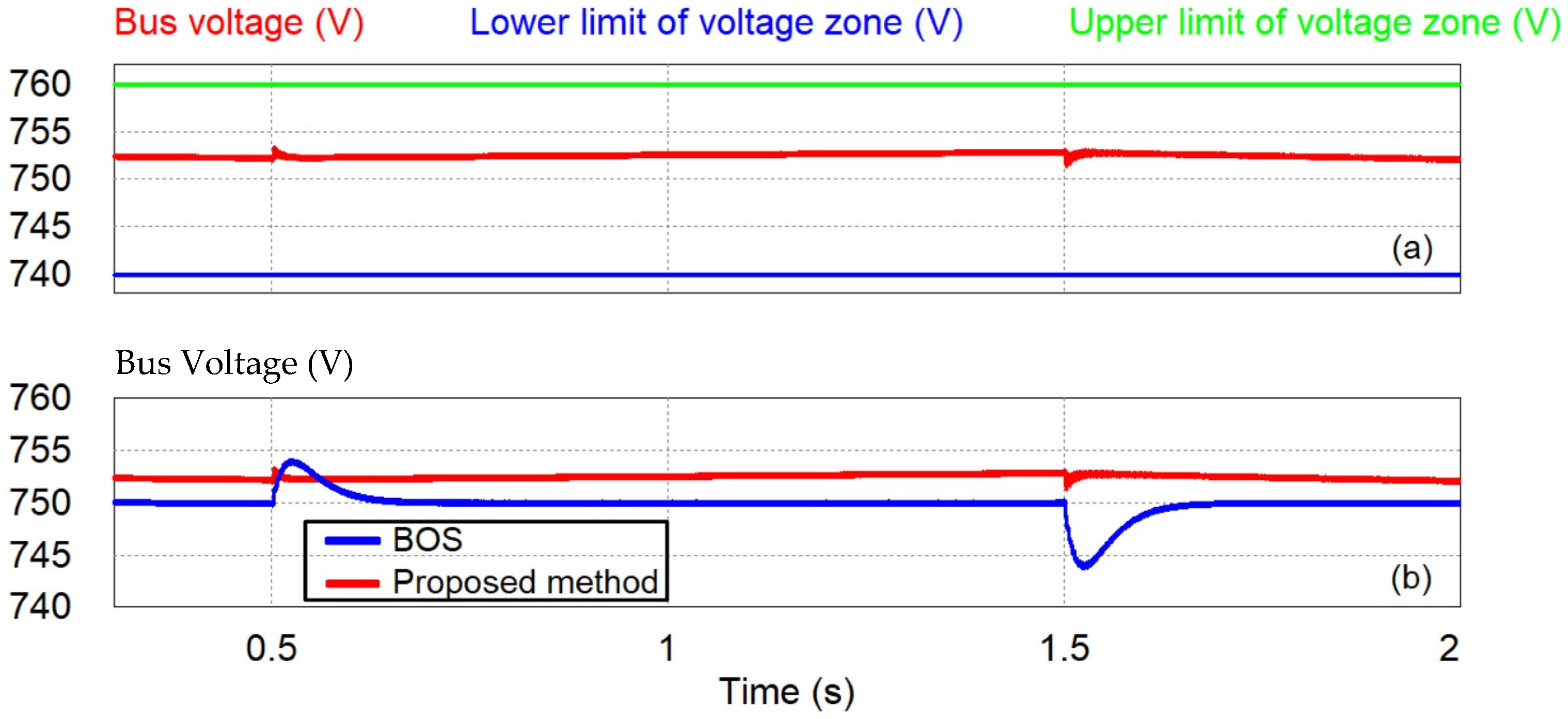
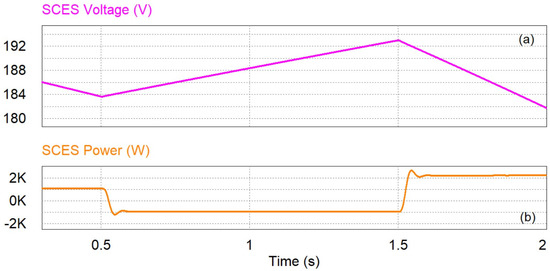
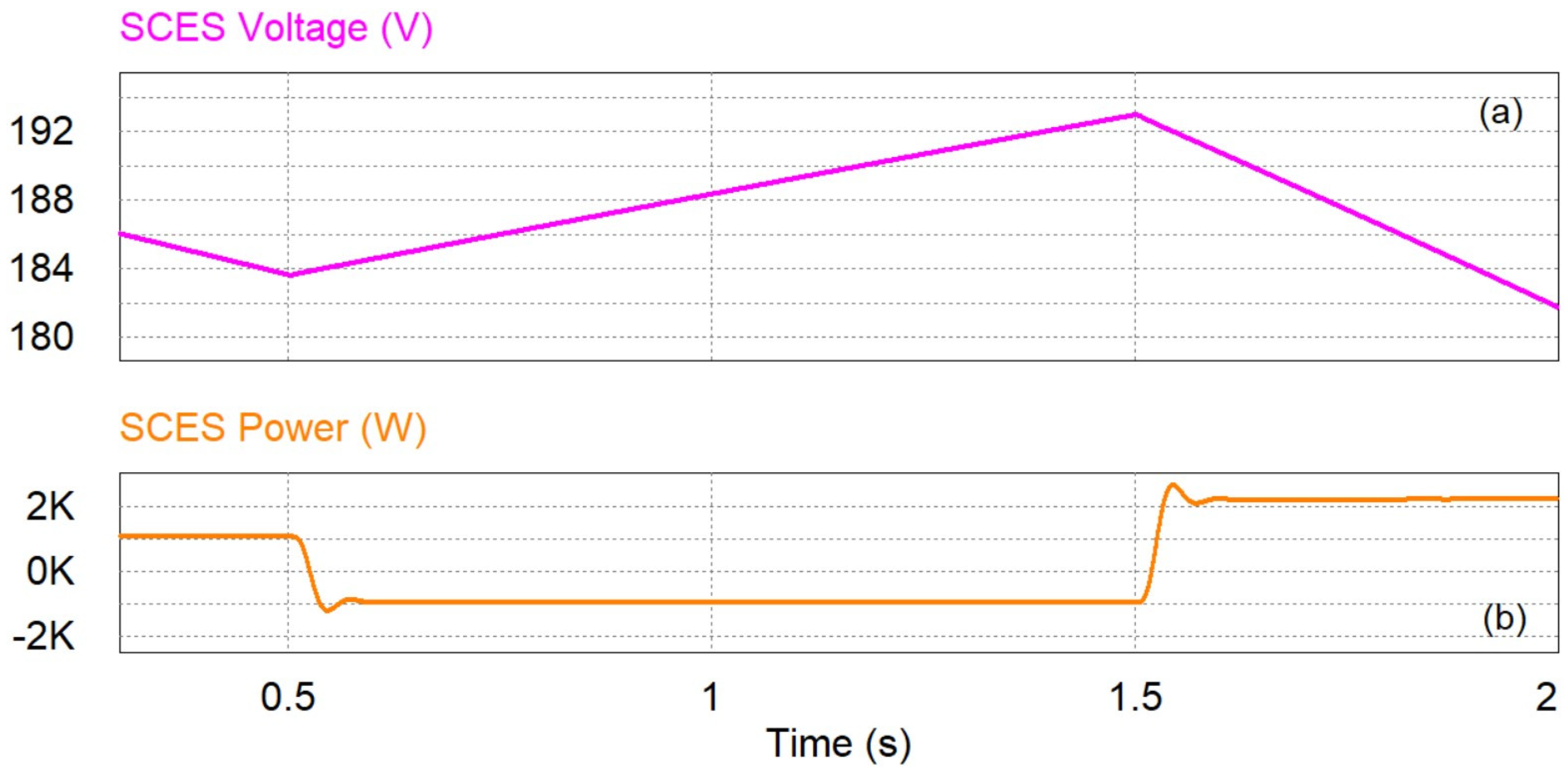
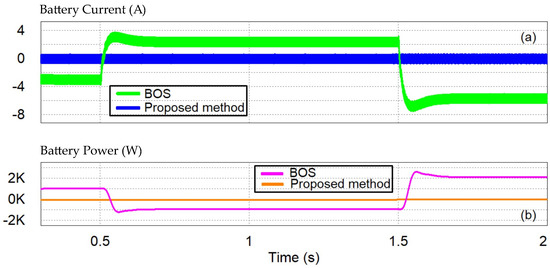
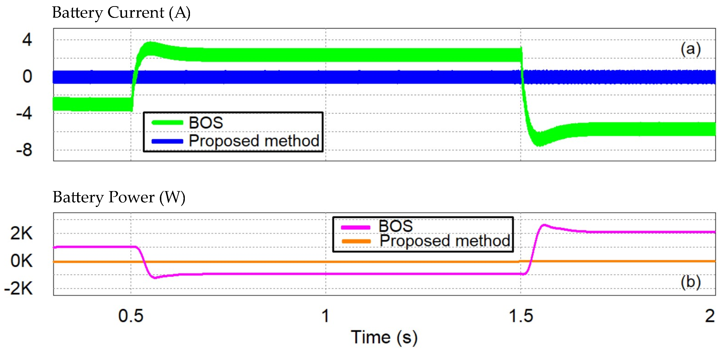
Due to the small power deficit before 0.5 s and after 1.5 s, the bus voltage is slightly decreasing, as shown in Figure 10a. In the intervening period of time, it is slightly increasing due to the elevated PV generation (Figure 10a). However, the bus voltage is maintained inside the zone defined by the VBUS zone, lower limit and the VBUS zone, upper limit throughout the simulation. Therefore, all the disturbances are compensated exclusively by the droop-controlled SCES since the battery is in an idle state, as illustrated in Figure 11a,b and Figure 12a,b, respectively. The rapid-responsive SCES instantly changes from discharging to charging and vice versa at 0.5 s and at 1.5 s, respectively (Figure 11a,b). Hence, the frequent small-scale battery operation is eliminated, its rapid current variations are avoided, and its service time is improved. Additionally, the bus voltage is well maintained near its nominal value in this case, as depicted in Figure 10a.
Figure 10.
(a) The DC bus voltage and the corresponding limits in the proposed method; (b) the DC bus voltage in both methods—Case 1.
Figure 11.
(a) The SCES voltage; (b) the SCES power—Case 1.
Figure 12.
(a) The battery current; (b) the battery power—Case 1.
On the contrary, in the case of a BOS, an overshoot of 4 V and an undershoot of 6 V are noticed in the microgrid bus, and the stress levels for the battery are increased. It is exposed to frequent cyclic activity and abrupt current variations, as shown in Figure 12a,b. Indicatively, the battery switches from discharging to charging at 0.5 s and from charging to discharging at 1.5 s, with rates of 238 A/s and 412 A/s, respectively. These rates pose challenges for the battery manufacturer and its lifespan.
4.1.2. Case 2: Operation with a High SCES SoC Level
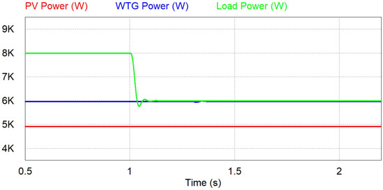
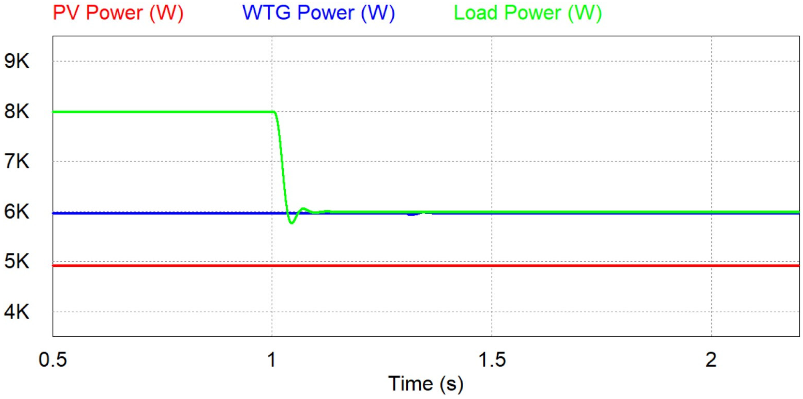
In this case, a high SoC level for the SCES system is considered since its initial voltage is 280 V, along with a step change in the load power at 1 s. Figure 13 indicates the power generated by the renewables and consumed by the load. Both PV and WTG operate at their MPP, generating 4.93 kW and 5.97 kW, respectively. The load demand is fixed at 8 kW up to 1 s, and then it changes sharply to 6 kW.
Figure 13.
The power of PV, WTG, and load—Case 2.
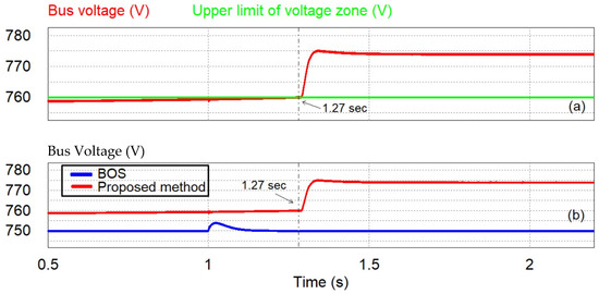
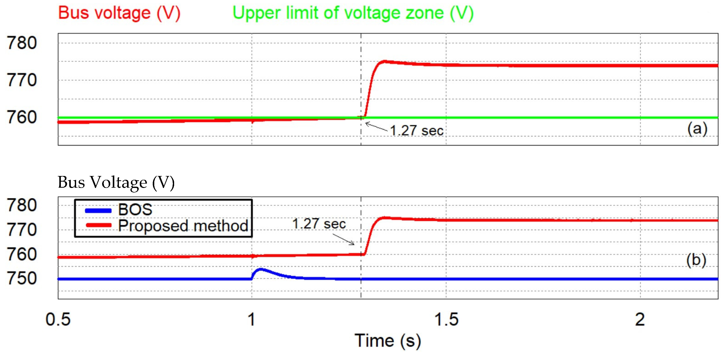
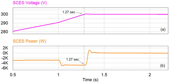
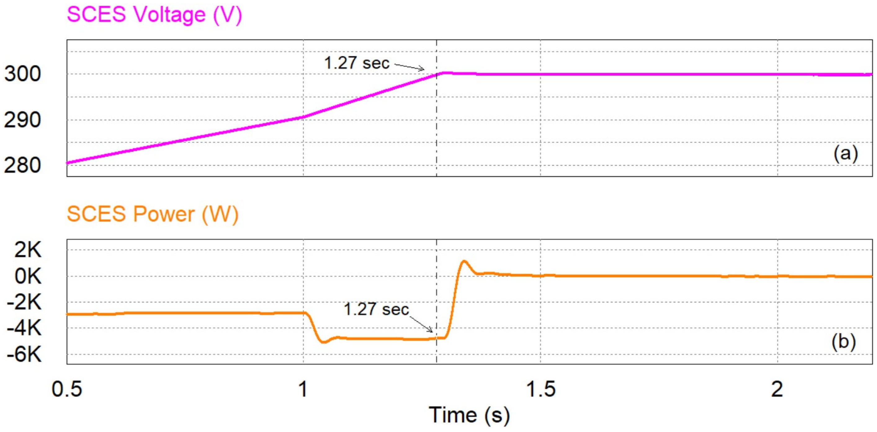
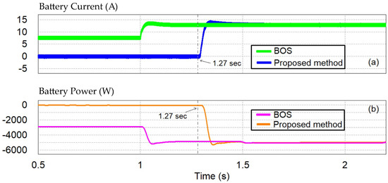
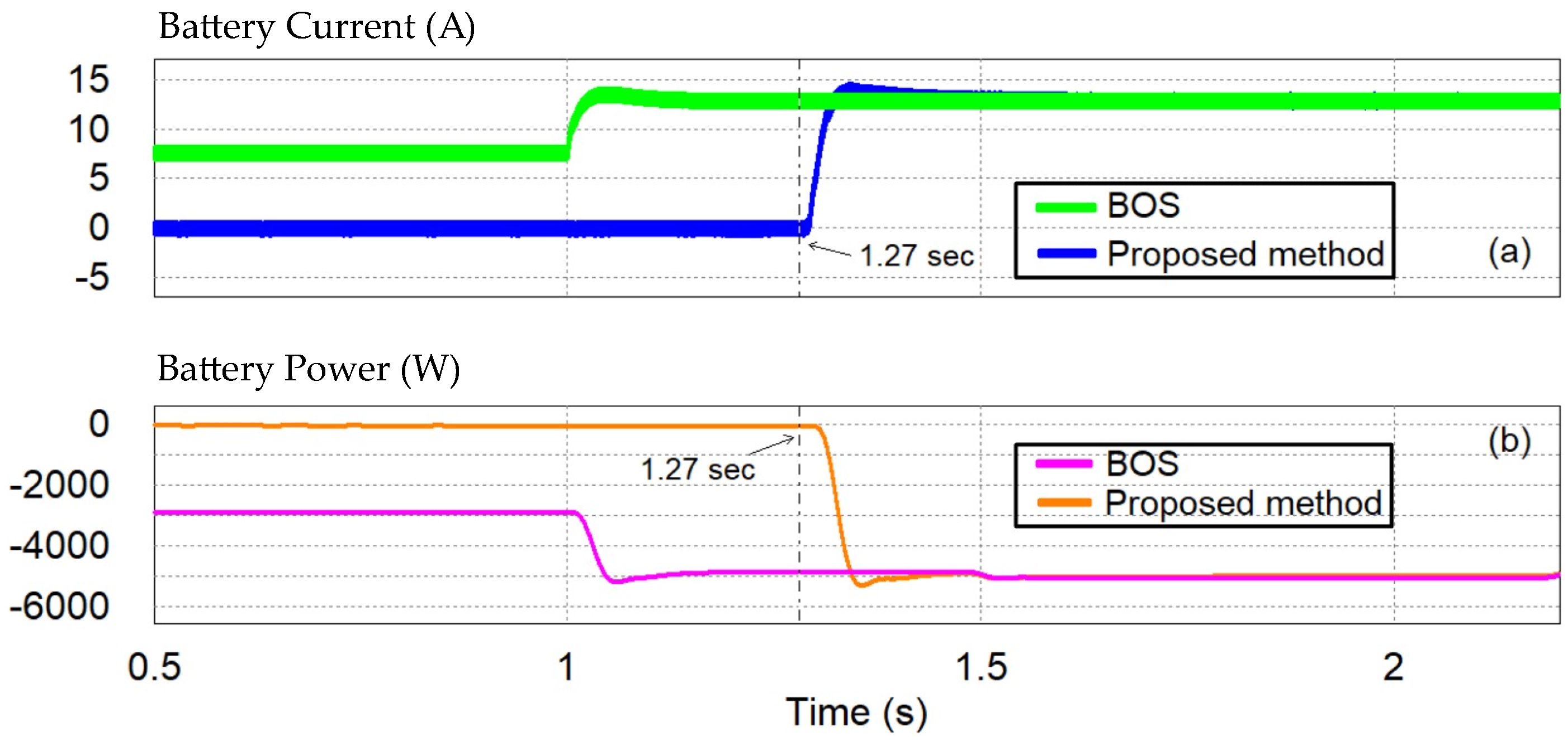
Due to the power surplus, the bus voltage is increasing, as shown in Figure 14a. Right after the load step reduction, the rise rate for the voltage gets bigger than before, since the power surplus is increased. Consequently, the bus voltage exceeds the VBUS zone, upper limit at 1.27 s as shown in Figure 14a. This time instant, the SCES reaches its maximum voltage, compensating the power surplus prior to this time instant, as depicted in Figure 15a,b, respectively. Therefore, until then, the battery is inactive (Figure 16a,b) and operating according to the proposed control method. Afterwards, the SCES enters the idle state, and the battery is triggered to charge, following its charging droop curve. Finally, the bus voltage is stabilized at 774 V, while the battery is charging at 12.9 A, as illustrated in Figure 14a and Figure 16a, respectively.
Figure 14.
(a) The DC bus voltage and the upper voltage limit in the proposed method; (b) the DC bus voltage in both methods—Case 2.
Figure 15.
(a) The SCES voltage; (b) the SCES power—Case 2.
Figure 16.
(a) The battery current; (b) the battery power—Case 2.
On the other hand, in the case of a BOS, the battery compensates the surplus before and after the load step reduction, charging with currents of 7.7 A and 12.9 A, respectively (Figure 16a). Thus, it regulates the bus voltage at its nominal value (Figure 14b). Once the load is reduced, the battery current changes with a rate of 288 A/s. However, under the proposed method, the battery is kept idle up to 1.27 s, and then the SCES is withdrawn while the battery is triggered to charge at a rate of 479 A/s.
4.1.3. Case 3: Operation with a Low SCES SoC Level
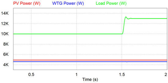
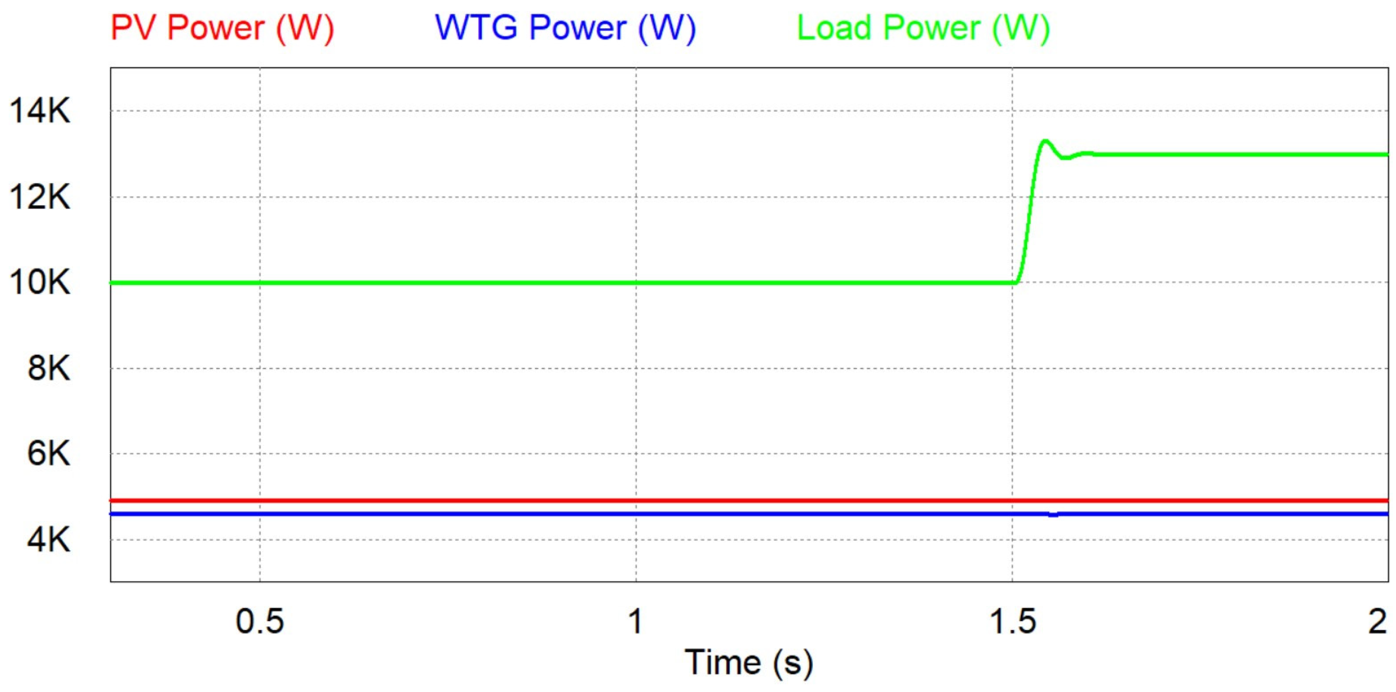
In this case, a low SoC level for the SCES system is considered since its initial voltage is 40 V, along with a step change in the load power at 1.5 s. Figure 17 depicts the power generated by the renewables and consumed by the load. Both PV and WTG follow the reference signals defined by their MPPT algorithms, generating 4.93 kW and 4.61 kW, respectively. The load demand is fixed at 10 kW up to 1.5 s, and then it changes abruptly to 13 kW.
Figure 17.
The power of PV, WTG, and load—Case 3.
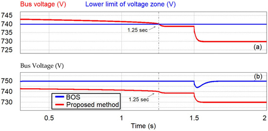
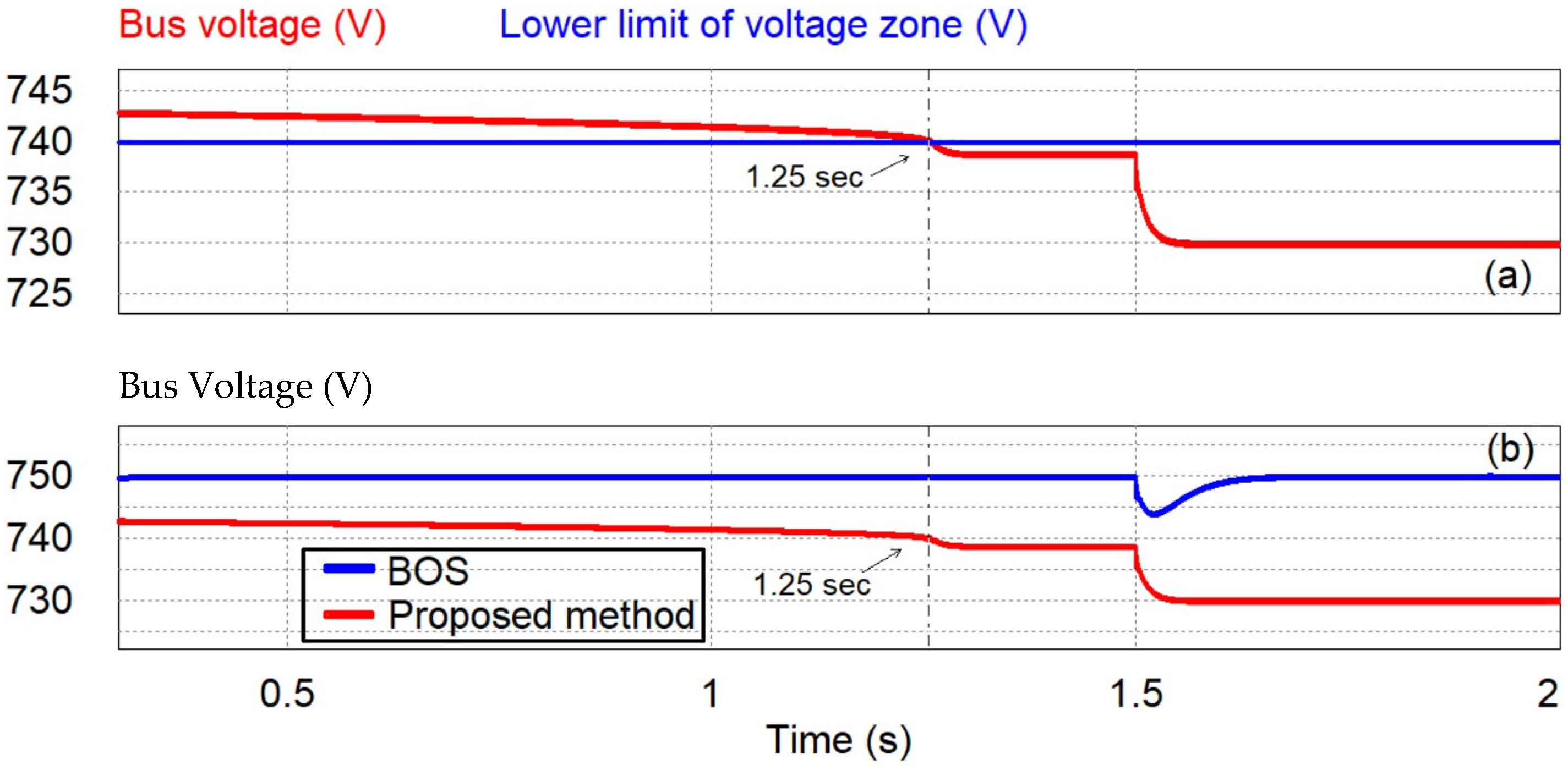
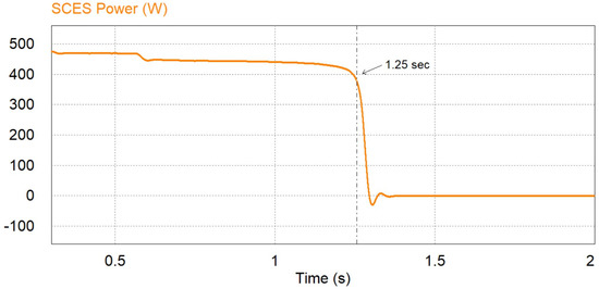
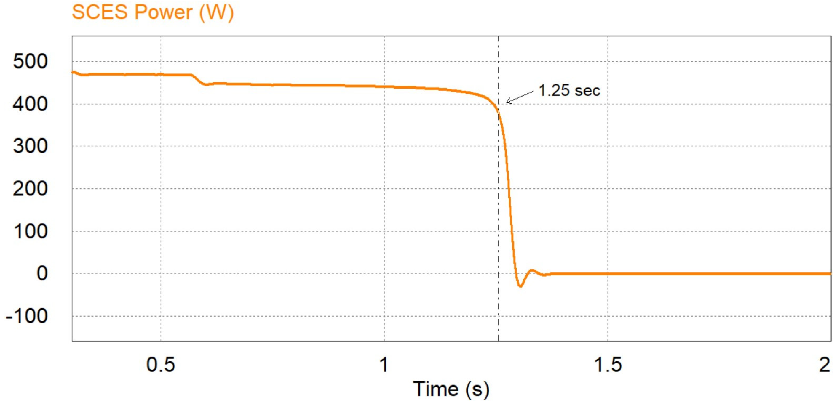
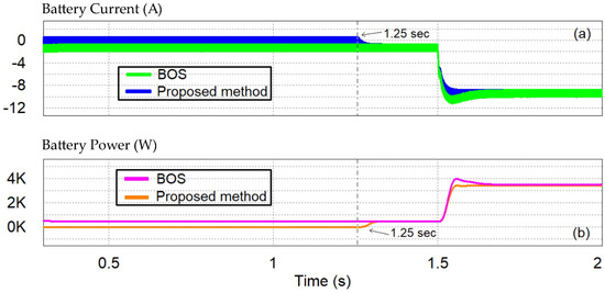
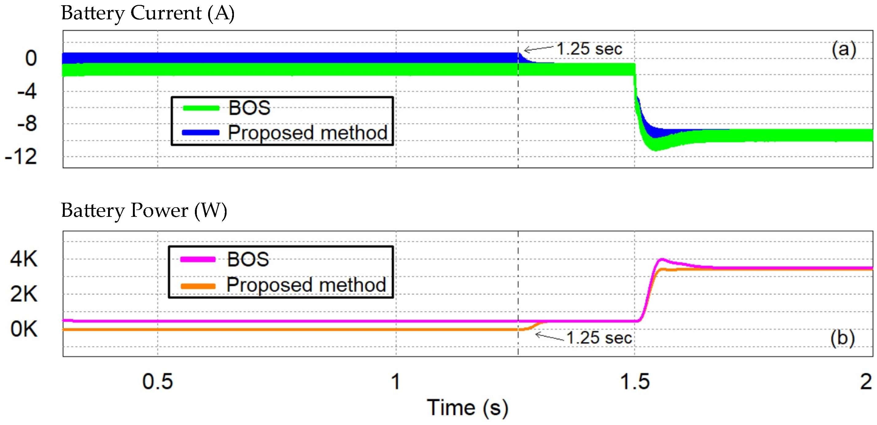
Due to the power deficit, the bus voltage is decreasing, as shown in Figure 18a. Consequently, it becomes smaller than the VBUS zone, lower limit at 1.25 s (Figure 18a). This time instant, the energy capacity of the SCES is depleted since it follows its droop curve and compensates the power deficit prior to this time instant, as depicted in Figure 19. Therefore, until then, the proposed control method keeps the battery idle (Figure 20a,b). Afterwards, the SCES enters the idle state, and the battery is triggered to discharge, following its discharging droop curve. The bus voltage is stabilized at 738.7 V, while the battery is discharging at 1.2 A, as illustrated in Figure 18a and Figure 20a, respectively. Finally, at 1.5 s, the load demand is increased, and therefore, the battery stabilizes the bus voltage at 729.9 V discharging at 9.3 A, according to its corresponding droop curve, as indicated in Figure 18a and Figure 20a, respectively.
Figure 18.
(a) The DC bus voltage and the lower voltage limit in the proposed method; (b) the DC bus voltage in both methods—Case 3.
Figure 19.
The SCES power—Case 3.
Figure 20.
(a) The battery current; (b) the battery power—Case 3.
On the contrary, in the case of a BOS, the battery compensates the deficit before and after the load increase, discharging with currents of 1.2 A and 9.3 A, respectively (Figure 20a). Thus, it regulates the bus voltage at its nominal value (Figure 18b). However, once the load is increased, the battery current changes with a rate of 436 A/s. Under the proposed method, though, the corresponding battery rate for the same load change is 413 A/s. Therefore, the droop control can reduce the working rates for the battery compared to a BOS when it compensates disturbances outside of the zone in which the SCES is active and the battery is inactive.
4.1.4. Comparison among the Previous Cases
Table 6 presents a comprehensive comparison among the previous three assessments in the presence of a BOS and a SCES/battery HESS controlled with the proposed method. The comparison includes the maximum DC bus voltage deviation from its nominal value, the battery status, and the battery current variations. From this table, it can be concluded that the SCES eliminates the frequent cyclic activity for the battery and reduces its current variations when the bus voltage is outside the narrow zone. Therefore, the presented scheme prolongs the battery’s lifespan.
Table 6.
Comparison among the previous assessments in the presence of a BOS and a SCES/battery HESS controlled with the proposed scheme.
4.2. Comparison with the Classical Droop Technique
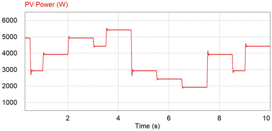
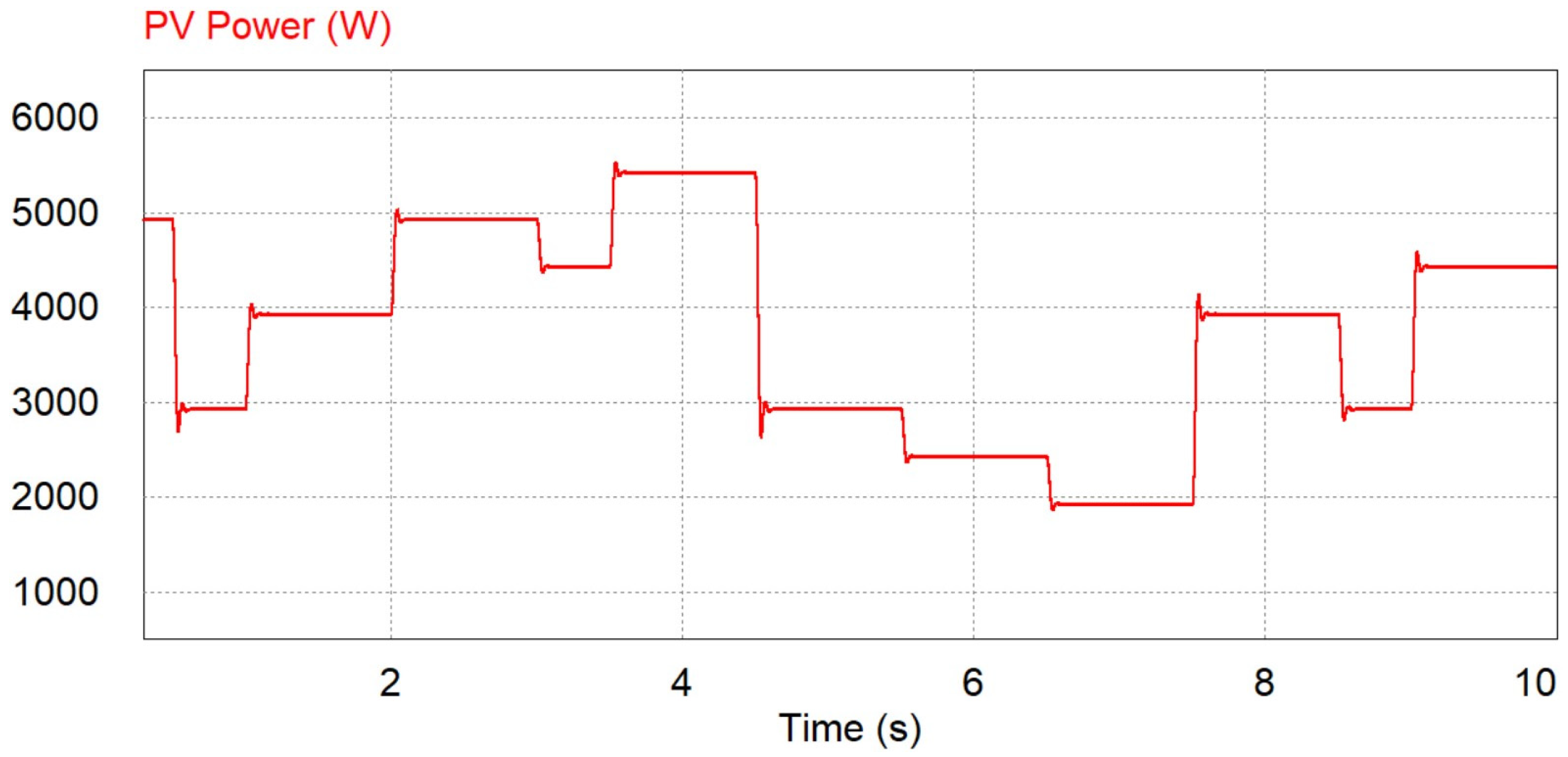
Here, the modified droop control method is compared with the classical droop approach for the SCES/battery HESS, considering a fluctuating PV generation profile [8]. The SoC level for the SCES system is set to 50% in both cases. Figure 21 indicates the power generated by the PV. The ambient temperature is fixed at 25 °C throughout the simulation, while the solar irradiation varies in the range of 400 W/m2 up to 1100 W/m2. Consequently, the PV generation fluctuates from 1.93 kW up to 5.43 kW, operating at its MPP. The wind speed is constant at 12 m/s and the WT generates 5.97 kW, extracting the maximum possible wind power, while the load demand is fixed at 10 kW.
Figure 21.
The power of PV.
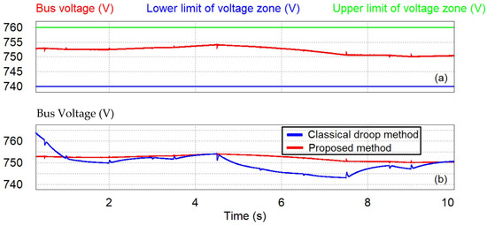
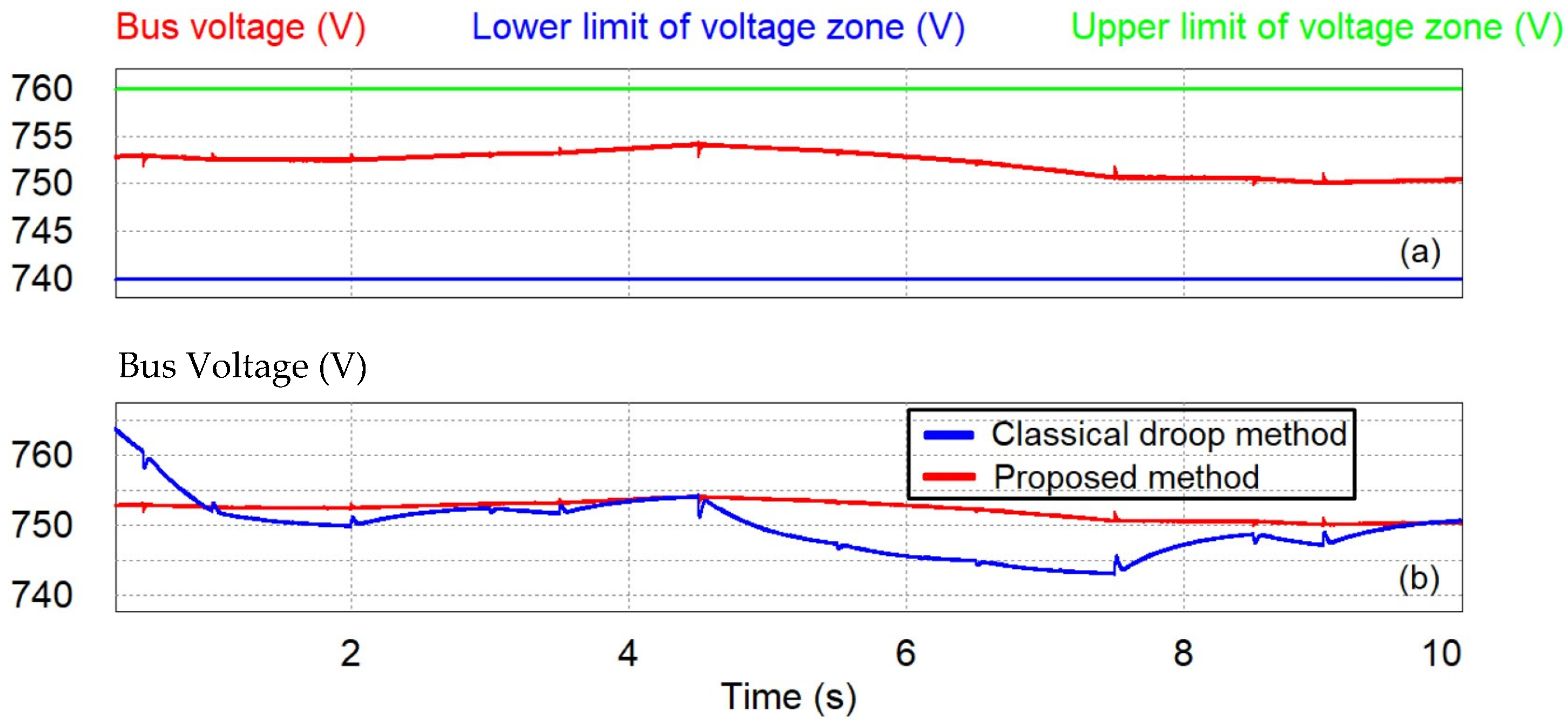
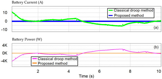
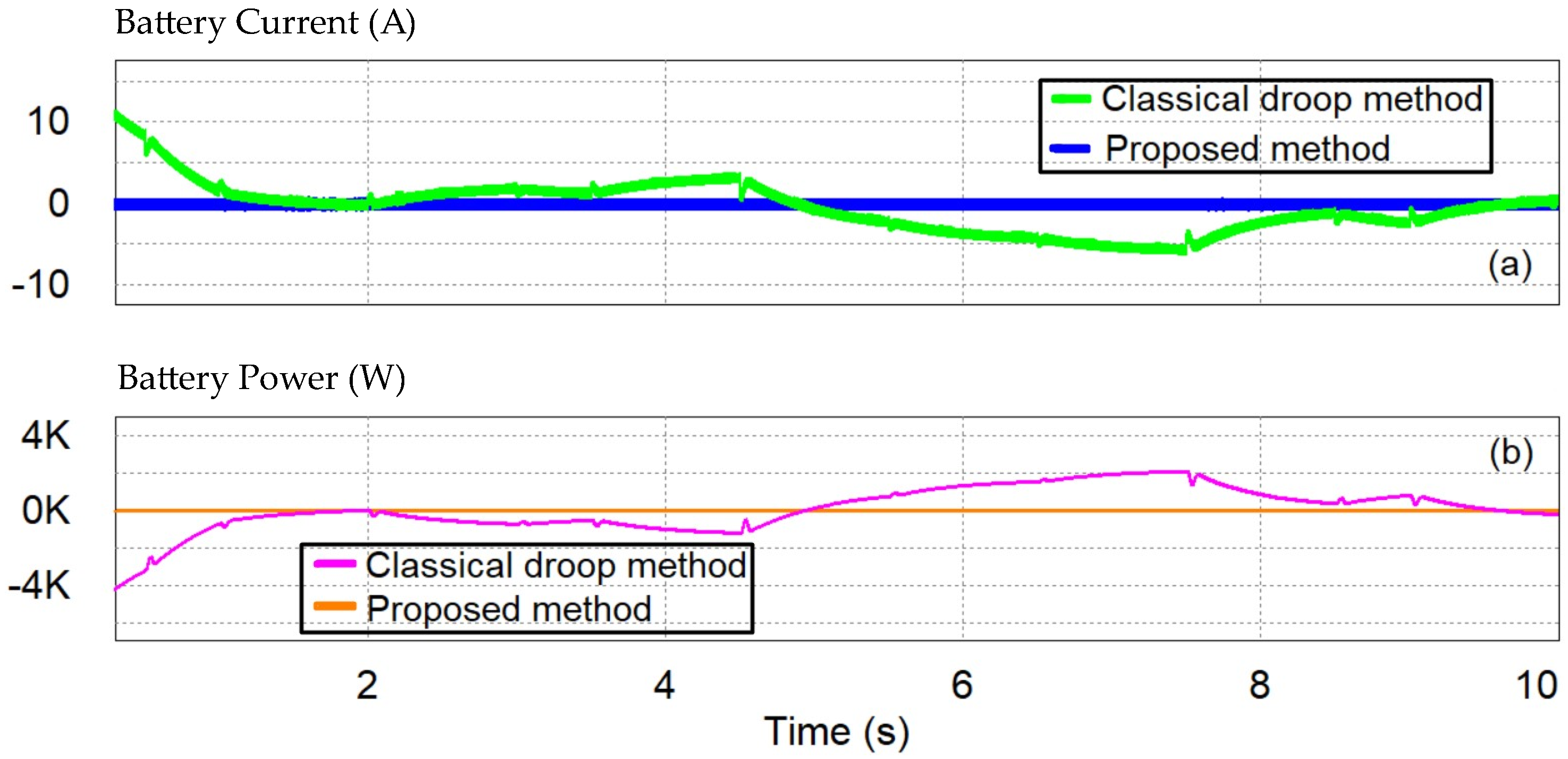
As shown in Figure 22a, the bus voltage is maintained inside the zone defined by the VBUS zone, lower limit and the VBUS zone, upper limit throughout the simulation when the proposed control method is employed. Therefore, all the disturbances are compensated exclusively by the rapid-responsive SCES, since the battery is in an idle state, as illustrated in Figure 23a,b and Figure 24a,b, respectively. Hence, the frequent small-scale cyclic operation for the battery is eliminated, and its service time is prolonged. Additionally, the bus voltage is satisfactorily maintained near its nominal value, as depicted in Figure 22a.
Figure 22.
(a) The DC bus voltage and the corresponding limits in the proposed method; (b) the DC bus voltage in both methods.
Figure 23.
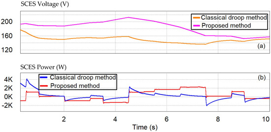
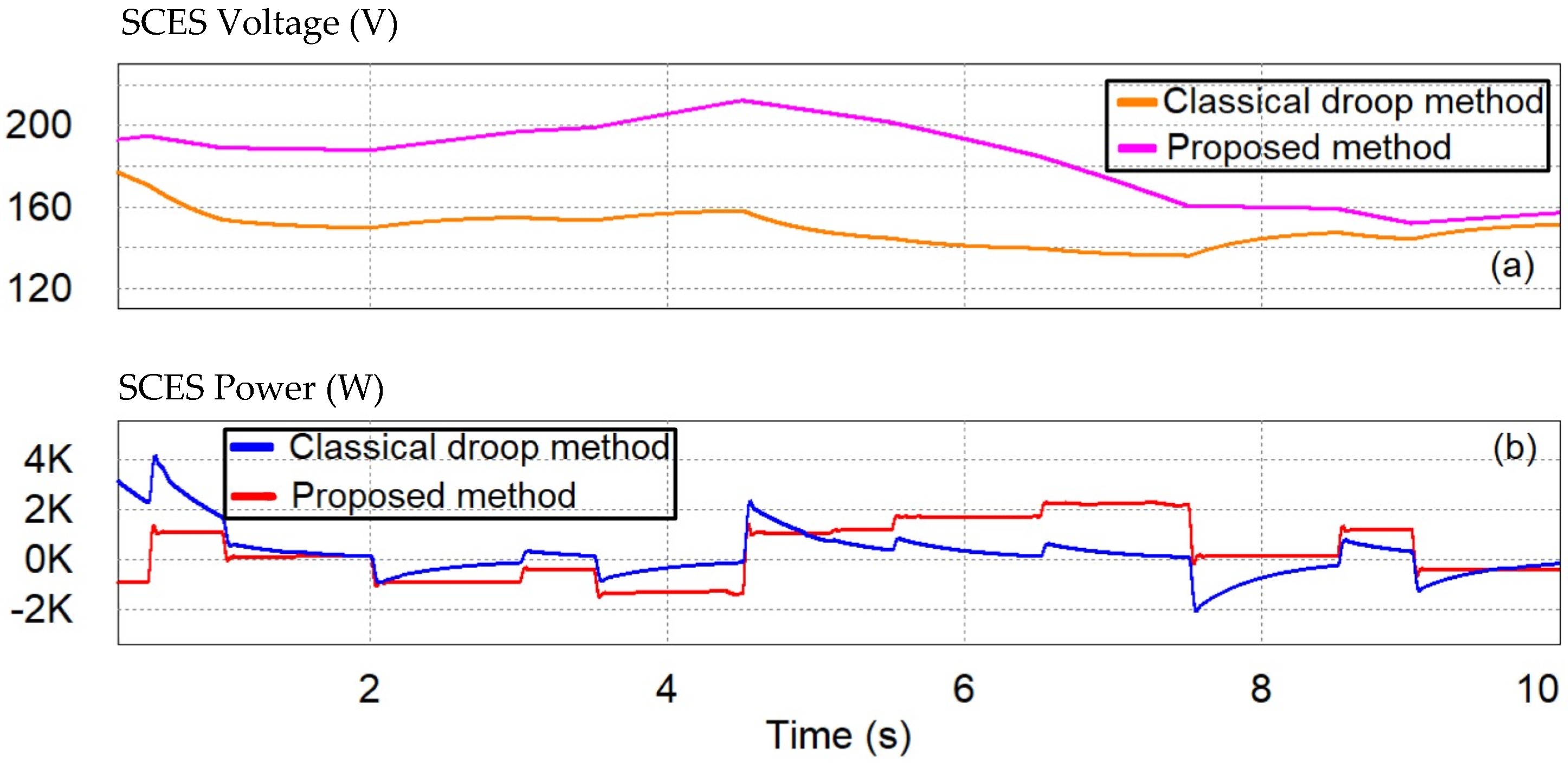
(a) The SCES voltage in both methods; (b) the SCES power in both methods.
Figure 24.
(a) The battery current; (b) the battery power.
On the contrary, when the classical droop method is employed, the fluctuation of the bus voltage around its nominal value is noticeably higher than that of the proposed scheme (Figure 22b). Indicatively, the bus voltage is equal to 743 V at 7.5 s. Both the SCES and the battery respond according to the bus voltage variations following their droop curves. Therefore, when the bus voltage decreases (increases), the SCES voltage decreases (increases) (Figure 22b and Figure 23a), and as long as the bus voltage is greater (lower) than its nominal value, the battery charges (discharges) (Figure 22b and Figure 24a). Consequently, the classical droop method is unable to eliminate the short-term activity of the battery but ensures smooth current variations for it. Table 7 presents a comprehensive comparison between the proposed droop method and the classical droop technique.
Table 7.
Comparison among the proposed droop method and the classical droop approach for the SCES/battery HESS.
5. Conclusions
A modified droop control algorithm for a SCES/battery HESS that is employed in a DC microgrid is proposed in this study. Unlike the centralized and distributed control methods, the presented scheme avoids the CC and communication links since the controllers of SCES and battery systems work independently. To eliminate the frequent cyclic activity and improve the lifetime of the energy-type battery, the power-type SCES is employed to regulate the bus voltage inside a narrow zone following its droop curve. Inside this zone, the battery is kept in idle mode. As soon as the bus voltage deviates from this band, the SCES is kept inactive, and the battery is triggered following a droop curve different for charging or discharging mode to stabilize the bus voltage. To evaluate the effectiveness of the proposed method under different scenarios and previously reported techniques, a comparison is made with a BOS and a hybrid SCES/battery system controlled with the classical droop method, and the results are summarized in Tables. The presented control scheme eliminates the short-term cyclic operation of the battery. Additionally, compared to a BOS, it reduces the battery working rates in cases where the bus voltage is outside the narrow band, to further improve its service time, and compared to the classical droop scheme, it regulates the bus voltage more effectively. Indicatively, the proposed droop method, in the first case of comparison with a BOS, zeroes the short-term activity of the battery and reduces the maximum bus voltage deviation by 45.23%, while in the third case of comparison with a BOS, it reduces the battery current variation by 5.28% for the same load step change. Furthermore, when it is compared with the classical droop method, it zeroes the short-term activity of the battery and reduces the maximum bus voltage deviation by 68.07%. On the other hand, once the SCES is withdrawn, the battery is triggered with a high charging or discharging rate.
Author Contributions
Conceptualization, P.P., K.O. and G.C.; methodology, P.P. and K.O.; software, P.P. and A.T.; validation, P.P., K.O. and A.T.; formal analysis, P.P. and A.T.; investigation, P.P.; resources, P.P. and A.T.; writing—original draft preparation, P.P. and K.O.; writing—review and editing, P.P., K.O. and G.C.; visualization, P.P.; supervision, K.O. and G.C.; project administration, G.C.; funding acquisition, G.C. All authors have read and agreed to the published version of the manuscript.
Funding
We acknowledge support of this work by the project “Development of New Innovative Low-Carbon Energy Technologies to Enhance excellence in the Region of Western Macedonia” (MIS 5047197) under the Action “Reinforcement of the Research and Innovation Infrastructure”, funded by the Operational Programme “Competitiveness, Entrepreneurship and Innovation” (NSRF 2014–2020) and co-financed by Greece and the European Union (European Regional Development Fund).
Data Availability Statement
No new data were created or analyzed in this study. Data sharing is not applicable to this article.
Conflicts of Interest
The authors declare no conflict of interest. The funders had no role in the design of the study; in the collection, analyses, or interpretation of data; in the writing of the manuscript; or in the decision to publish the results.
References
- Tan, K.M.; Babu, T.S.; Ramachandaramurthy, V.K.; Kasinathan, P.; Solanki, S.G.; Raveendran, S.K. Empowering smart grid: A comprehensive review of energy storage technology and application with renewable energy integration. J. Energy Storage 2021, 39, 102591. [Google Scholar] [CrossRef] [Scilit]
- Sebestyén, V. Renewable and Sustainable Energy Reviews: Environmental impact networks of renewable energy power plants. Renew. Sustain. Energy Rev. 2021, 151, 111626. [Google Scholar] [CrossRef] [Scilit]
- A European Green Deal. Available online: https://ec.europa.eu/info/strategy/priorities-2019-2024/european-green-deal_en (accessed on 11 January 2023).
- Oureilidis, K.; Malamaki, K.-N.; Gallos, K.; Tsitsimelis, A.; Dikaiakos, C.; Gkavanoudis, S.; Cvetkovic, M.; Mauricio, J.M.; Ortega, J.M.M.; Ramos, J.L.; et al. Ancillary Services Market Design in Distribution Networks: Review and Identification of Barriers. Energies 2020, 13, 917. [Google Scholar] [CrossRef] [Scilit]
- Yang, N.; Paire, D.; Gao, F.; Miraoui, A. Power Management Strategies for Microgrid—A Short Review. In Proceedings of the 2013 IEEE Industry Applications Society Annual Meeting, Lake Buena Vista, FL, USA, 6–11 October 2013. [Google Scholar]
- Sun, J.; Lin, W.; Hong, M.; Loparo, K.A. Voltage Regulation of DC-Microgrid with PV and Battery. IEEE Trans. Smart Grid 2020, 11, 4662–4675. [Google Scholar] [CrossRef] [Scilit]
- Dragicevic, T.; Lu, X.; Vasquez, J.C.; Guerrero, J.M. DC Microgrids—Part II: A Review of Power Architectures, Applications, and Standardization Issues. IEEE Trans. Power Electron. 2016, 31, 3528–3549. [Google Scholar] [CrossRef] [Scilit]
- Ni, F.; Zheng, Z.; Xie, Q.; Xiao, X.; Zong, Y.; Huang, C. Enhancing resilience of DC microgrids with model predictive control based hybrid energy storage system. Int. J. Electr. Power Energy Syst. 2021, 128, 106738. [Google Scholar] [CrossRef] [Scilit]
- Luo, X.; Wang, J.; Dooner, M.; Clarke, J. Overview of current development in electrical energy storage technologies and the application potential in power system operation. Appl. Energy 2015, 137, 511–536. [Google Scholar] [CrossRef] [Scilit]
- Li, J.; Gee, A.M.; Zhang, M.; Yuan, W. Analysis of battery lifetime extension in a SMES-battery hybrid energy storage system using a novel battery lifetime model. Energy 2015, 86, 175–185. [Google Scholar] [CrossRef] [Scilit]
- Zhang, Q.; White, R.E. Capacity fade analysis of a lithium ion cell. J. Power Sour. 2008, 179, 793–798. [Google Scholar] [CrossRef] [Scilit]
- Ruan, H.; Barreras, J.V.; Engstrom, T.; Merla, Y.; Millar, R.; Wu, B. Lithium-ion battery lifetime extension: A review of derating methods. J. Power Sour. 2023, 563, 232805. [Google Scholar] [CrossRef] [Scilit]
- Ndiaye, A.; Locment, F.; De Bernardinis, A.; Sechilariu, M.; Redondo-Iglesias, E. A Techno-Economic Analysis of Energy Storage Components of Microgrids for Improving Energy Management Strategies. Energies 2022, 15, 1556. [Google Scholar] [CrossRef] [Scilit]
- Lee, N.; Nee, C.H.; Yap, S.S.; Tham, K.K.; You, A.H.; Yap, S.L.; Arof, A.K.B.M. Capacity Sizing of Embedded Control Battery–Supercapacitor Hybrid Energy Storage System. Energies 2022, 15, 3783. [Google Scholar] [CrossRef] [Scilit]
- Yaseen, M.; Khattak, M.A.K.; Humayun, M.; Usman, M.; Shah, S.S.; Bibi, S.; Hasnain, B.S.U.; Ahmad, S.M.; Khan, A.; Shah, N.; et al. A Review of Supercapacitors: Materials Design, Modification, and Applications. Energies 2021, 14, 7779. [Google Scholar] [CrossRef] [Scilit]
- Olivares, D.E.; Mehrizi-Sani, A.; Etemadi, A.H.; Canizares, C.A.; Iravani, R.; Kazerani, M.; Hajimiragha, A.H.; Gomis-Bellmunt, O.; Saeedifard, M.; Palma-Behnke, R.; et al. Trends in Microgrid Control. IEEE Trans. Smart Grid 2014, 5, 1905–1919. [Google Scholar] [CrossRef] [Scilit]
- Lin, X.; Zamora, R. Controls of hybrid energy storage systems in microgrids: Critical review, case study and future trends. J. Energy Storage 2022, 47, 103884. [Google Scholar] [CrossRef] [Scilit]
- Han, Y.; Zhang, K.; Li, H.; Coelho, E.A.; Guerrero, J.M. MAS-Based Distributed Coordinated Control and Optimization in Microgrid and Microgrid Clusters: A Comprehensive Overview. IEEE Trans. Power Electron. 2018, 33, 6488–6508. [Google Scholar] [CrossRef] [Scilit]
- Abhishek, A.; Ranjan, A.; Devassy, S.; Verma, B.K.; Ram, S.K.; Dhakar, A.K. Review of hierarchical control strategies for DC microgrid. IET Renew. Power Gener. 2020, 14, 1631–1640. [Google Scholar] [CrossRef] [Scilit]
- Kollimalla, S.K.; Mishra, M.K.; Ukil, A.; Gooi, H.B. DC Grid Voltage Regulation Using New HESS Control Strategy. IEEE Trans. Sustain. Energy 2017, 8, 772–781. [Google Scholar] [CrossRef] [Scilit]
- Sarojini, R.K.; Palanisamy, K.; Sanjeevikumar, P.; Nielsen, J.B.H. Inertia emulation control technique based frequency control of grid-connected single-phase rooftop photovoltaic system with battery and supercapacitor. IET Renew. Power Gener. 2020, 14, 1156–1163. [Google Scholar] [CrossRef] [Scilit]
- Jithin, S.; Rajeev, T. Novel adaptive power management strategy for hybrid AC/DC microgrids with hybrid energy storage systems. J. Power Electron. 2022, 22, 2056–2068. [Google Scholar] [CrossRef] [Scilit]
- Siad, S.B.; Iovine, A.; Damm, G.; Galai-Dol, L.; Netto, M. Nonlinear Hierarchical Easy-to-Implement Control for DC MicroGrids. Energies 2022, 15, 969. [Google Scholar] [CrossRef] [Scilit]
- Sidharthan, V.P.; Kashyap, Y.; Kosmopoulos, P. Adaptive-Energy-Sharing-Based Energy Management Strategy of Hybrid Sources in Electric Vehicles. Energies 2023, 16, 1214. [Google Scholar] [CrossRef] [Scilit]
- Li, J.; Xiong, R.; Mu, H.; Cornélusse, B.; Vanderbemden, P.; Ernst, D.; Yuan, W. Design and real-time test of a hybrid energy storage system in the microgrid with the benefit of improving the battery lifetime. Appl. Energy 2018, 218, 470–478. [Google Scholar] [CrossRef] [Scilit]
- Li, J.; Yang, Q.; Robinson, F.; Liang, F.; Zhang, M.; Yuan, W. Design and test of a new droop control algorithm for a SMES/battery hybrid energy storage system. Energy 2017, 118, 1110–1122. [Google Scholar] [CrossRef] [Scilit]
- POWERSIM User Manual. Available online: https://www.powersimtech.com/wp-content/uploads/2021/01/PSIMUser-Manual.pdf (accessed on 11 January 2023).
- Díaz-González, F.; Sumper, A.; Gomis-Bellmunt, O.; Villafáfila-Robles, R. A review of energy storage technologies for wind power applications. Renew. Sustain. Energy Rev. 2012, 16, 2154–2171. [Google Scholar] [CrossRef] [Scilit]
- Tremblay, O.; Dessaint, L.-A. Experimental Validation of a Battery Dynamic Model for EV Applications. World Electr. Veh. J. 2009, 3, 289–298. [Google Scholar] [CrossRef] [Scilit]
- de Brito, M.A.G.; Galotto, L.; Sampaio, L.P.; e Melo, G.d.A.; Canesin, C.A. Evaluation of the Main MPPT Techniques for Photovoltaic Applications. IEEE Trans. Ind. Electron. 2013, 60, 1156–1167. [Google Scholar] [CrossRef] [Scilit]
- Sera, D.; Mathe, L.; Kerekes, T.; Spataru, S.V.; Teodorescu, R. On the Perturb-and-Observe and Incremental Conductance MPPT Methods for PV Systems. IEEE J. Photovolt. 2013, 3, 1070–1078. [Google Scholar] [CrossRef] [Scilit]
- Kotb, K.M.; Elmorshedy, M.F.; Salama, H.S.; Dán, A. Enriching the stability of solar/wind DC microgrids using battery and superconducting magnetic energy storage based fuzzy logic control. J. Energy Storage 2022, 45, 103751. [Google Scholar] [CrossRef] [Scilit]
- Abdullah, M.A.; Yatim, A.H.M.; Tan, C.W.; Saidur, R. A review of maximum power point tracking algorithms for wind energy systems. Renew. Sustain. Energy Rev. 2012, 16, 3220–3227. [Google Scholar] [CrossRef] [Scilit]
- IEEE Recommended Practice for the Design and Application of Power Electronics in Electrical Power Systems. In IEEE Std 1662–2016 (Revision of IEEE Std 1662–2008); IEEE: Piscataway, NJ, USA, 2017; pp. 1–68.
- Salama, H.S.; Kotb, K.M.; Vokony, I.; Dán, A. The Role of Hybrid Battery–SMES Energy Storage in Enriching the Permanence of PV–Wind DC Microgrids: A Case Study. Eng 2022, 3, 207–223. [Google Scholar] [CrossRef] [Scilit]

Disclaimer/Publisher’s Note: The statements, opinions and data contained in all publications are solely those of the individual author(s) and contributor(s) and not of MDPI and/or the editor(s). MDPI and/or the editor(s) disclaim responsibility for any injury to people or property resulting from any ideas, methods, instructions or products referred to in the content. |
© 2023 by the authors. Licensee MDPI, Basel, Switzerland. This article is an open access article distributed under the terms and conditions of the Creative Commons Attribution (CC BY) license (https://creativecommons.org/licenses/by/4.0/).