


Abstract
The development of battery-powered electric aircraft for use in commercial aviation involves various performance- and safety-based challenges. Cells with high energy densities (for instance Li-Ion pouches) are required to meet the performance requirements, with those currently available encompassing a risk of thermal runaway and other failures. To enable their use, this work provides an investigation into battery abuse conditions and their effect on the overall safety of the system, tailored to electric aviation. A system architecture is presented for a battery-powered electric aircraft, including recommended mitigation methods for the presented failure modes. A framework for determining the overall State of Safety based on the relevant abuse conditions is presented. It is found that the influence of atmospheric operation conditions, flight profiles and vibrations provide the most notable differences between battery-associated risks for aircraft and ground vehicle purposes. Quantification and experimental validation of the impact of these conditions is recommended as a direction for future work.
1. Introduction
Electric vehicles such as cars, buses and trucks have seen a large growth in development and use over the last decades. Maritime mobility methods have also become available in battery-powered variants of various types. A key sector within mobility has not seen a similar widespread implementation of batteries as main energy carriers: aviation. Battery-powered electric aircraft (BPEA) have long been deemed challenging to design and operate, mainly due to the mass of the batteries and electrical components [1].
Unmanned drones and electric vertical take off and landing (eVTOL) aircraft form the majority of BPEA that are currently in operation. Their size and use scenarios allow for the use of batteries because of their short-range operation. The 2 passengers (pax) Pipistrel Velis Electro [2] is the first certified BPEA for passengers. Larger models, such as the Archer Maker (5 pax) [3] are under development. Finally, at least two large-scale BPEA, fitting within the CS-25 large plane category, are also in development. These are the MAEVE Jet (hybrid, 76 or 100 pax) [4] and the Elysian E9X (90 pax) [5].
Enabling battery-powered electric aviation requires the inclusion of energy storage technologies at high energy and power density. Initially, it was estimated that large-scale commercial aircraft would require pack-level energy densities around 1000 Wh/kg [1]. However, research by De Vries et al. [6] showcases the possibility of using 360 Wh/kg pack-level densities in CS-25 aircraft.
In addition to performance-related challenges, safety aspects form a major barrier when it comes to the introduction of BPEA for commercial applications. To achieve pack-level energy densities required for commercial aviation, high-level energy density cells (>450 Wh/kg) are required. Although these are in development [7], these values can mostly be found in pouch Li-Ion cells. These cell types provide excellent energy density values, yet are sensitive and can experience thermal runaway (TR) [8,9,10]. This term is described by the European Union Aviation Safety Agency (EASA) [11] as: “A thermal runaway may result in the release of heat, smoke, flames and in some cases in explosion”. Although this is already an issue in ground-level battery systems, inclusion in aviation adds an additional risk factor. This point is illustrated by Viswanathan et al., who mention in their paper [1] that: “An overheated or smoking battery in a car means pull over, not so easy at 12 km in the air”.
Thermal runaway is often researched and documented (e.g., [12,13,14]) because it can lead to catastrophic failure of the battery system. Next to this, a significant risk associated with thermal runaway is that a single event can trigger further events. It is important to note that thermal runaway as a failure mode is in itself the result of other failure modes. Hence, this paper focuses on the failure modes that can lead to a thermal runaway or other catastrophic failure modes and how these can be observed and possibly prevented.
1.1. Safety Risks in Aviation
The most infamous example of a thermal runaway event in a commercial aircraft is that of the Boeing 787 Dreamliner. On 16 January 2013, all operating Dreamliners were indefinitely grounded due to numerous incidents with Li-Ion batteries onboard the aircraft [15]. On 7 January 2013, a fire was discovered onboard a 787 Dreamliner parked at a gate at General Edward Lawrence Logan International Airport (BOS), Boston, Massachusetts, USA. The accident report by the National Transportation Safety Board (NTSB) [16] highlights the complexity of the failure modes, along with the complexity of the surrounding technical and social/regulatory systems.
Specific cell-level failure conditions were found in the form of “cell internal short circuiting and the potential for thermal runaway of one or more battery cells, fire, explosion, and flammable electrolyte release”. Two possible physical causes for these events were discussed: “cell manufacturing defects and oversight of cell manufacturing processes” and “thermal management of large-format lithium-ion batteries”. The guidance of manufacturers within the process of determining and justifying assumptions in safety assessments was also questioned. If more centralized knowledge regarding safety risks was available, it could have improved the assessment of the company, reducing the possibility of failure. Similarly, the novelty of the Li-Ion battery system meant that there was “insufficient guidance for Federal Aviation Administration (FAA) certification engineers to use during the type certification process to ensure compliance with applicable requirements”.
1.2. Regulations and Standards
Aviation standards are among the most strict, mainly due to the difficulty of evacuation during operation. This applies to all forms of aviation, but especially commercial aircraft due to the presence of passengers on board. Aircraft are classified based on their dimensions, take-off mass, and number of passengers present. These classifications are set by the FAA in the US and the EASA in Europe. For each classification, certification specifications are in place. An aircraft is only allowed to be used after certification of both its components and the total aircraft. This was also done for the Li-Ion battery system installation in the earlier-discussed Dreamliner aircraft [17].
Besides the present certification process, means of compliance (MOC) guidelines are published by the FAA and EASA. These guidelines propose a set of requirements for aircraft components and systems to aid in the certification process. They also prescribe testing procedures to validate the posed requirements. As of the writing of this article, a few MOC documents related to propulsion batteries for aviation are published. The most complete relates to e-VTOL aircraft [18]. Next to this, the AC20-184 guideline from the FAA [19] focuses on the use of rechargeable lithium-ion batteries within aircraft. This does however not include those for use in propulsion systems.
1.3. Other Forms of Electric Mobility
The use of battery cells is more prominent in electric vehicles. Here, more standards and regulations are available and can provide valuable insights into the integration process and associated risks and mitigation methods. An elaborate review by Ruiz et al. [20] highlights many of the focus points within the safety standards of Li-Ion batteries within the automotive industry. They found that abuse testing is required in different domains: mechanical (dropping, penetration, vibrations, etc.), electrical (short circuits, overcharge/overdischarge), environmental (temperature), and chemical (emissions and flammability). Furthermore, they note the importance of identifying the difference in abuse conditions between the chosen test level and the complete integration within the vehicle.
A detailed look at the failure modes present within a Li-Ion battery pack used in the automotive industry is presented by Gandoman et al. [21]. Their work focuses on identifying failure modes and conditions for Li-Ion battery packs and correlating them to the aforementioned standards by looking at normal operation degradation and abnormal abuse conditions.
In a more similar case, the possible use of Li-Ion batteries in space applications is investigated in [22]. The work identifies similar risks associated with extreme temperatures (where cold becomes more of an issue than in automotive), vibrations (during launch and flight) and electrical challenges. In contrast to the automotive field, the safety aspect focuses more on the durability of the vehicle or satellite compared to the passengers. Furthermore, they find that prismatic and cylindrical cells are more commonly used in aerospace than pouch-cells, mainly due to the risk of swelling associated with the latter.
NASA also discussed the risks associated with Li-Ion batteries in spacecraft [23], finding similar risk groups. Their report also mentions the use in crewed aircraft, specifically highlighting a two-fold fault tolerance to protect the crew. Furthermore, tests should be performed at temperature and vibration levels higher than those anticipated in the mission. However, no particular tests are proposed or quantified.
1.4. Research Goals and Paper Overview
Enabling commercial battery-powered aviation requires the traversal of a trade-off between performance and safety aspects. The use of high energy density battery cells implies associative safety risks that should be accounted for. To validate the possible use of these cells in a battery system for BPEA, this work combines research into the safety risks associated with electric flight and battery integration with a proposed architecture design for such a battery system. This allows allocation of risks to specific components, functions or subsystems within the system design. We compare the aviation-based safety risks with those known from ground-based vehicles and the aforementioned incidents with the Dreamliner aircraft.
In an ideal situation, the safety of the electric energy storage system (EESS) can be monitored and communicated in real-time. This requires the translation of both quantitative and qualitative safety aspects/abuses/risks into a metric. The State of Safety (SoS) [24] is one such metric. To fully identify the SoS, it is important to investigate which parameters should be put into the metric calculation. Hence, this work combines the design of a system architecture for a BPEA battery system by R. van Zijl with a literature review done by J. Dalitz during his thesis [25] (under supervision of the other authors) on the safety risks associated with the EESS in electric aviation. It serves the purpose of defining the parameters and to connect them to the design phase, highlighting which risks have to be monitored during use and what can be prevented during design. The work acts as a framework for further work, which focuses on the translation of these parameters into a functional, numerical SoS calculation.
Section 2 presents the general system architecture for a large-scale BPEA. Hereafter, we present a literature review on battery safety and abuse conditions in Section 3. The framework consisting of the applied failure modes and propagation paths in situ is presented in Section 4, where after these the methods are discussed in Section 5. Finally, conclusions and recommendations for further research/work are presented in Section 6.
2. System Architecture of a BPEA Battery System
Identifying abuses within an aircraft battery requires the presence of such a battery system. Due to the limited availability of in-operation BPEA, as well as accompanying patents or design examples (except for, e.g., [26,27]), this section is used to present a system architecture for a BPEA battery system. At first, a number of system functions/function groups are defined. The interfaces between the battery system and adjacent systems within the aircraft are also investigated. This leads to the creation of a system architecture containing functions, known physical components and these interfaces. Using the architecture, abuse causes can be found and allocated to parts of the system or external systems.
2.1. Functions
Presented below is a generalized list of functions for an aircraft battery system (or EESS), partially based on the MOC for e-VTOL aircraft [18]. It is presented in this way to ensure that a broad scope of functions is captured, as many specific functions exist. Charging the battery system itself is not included, as that should belong to an external charging system.
- Store Energy. The main function of a battery system is to store electrical energy. This can be seen as general system functionality, as well as being allocated to specific components within the battery.
- Supply Power and Energy. Exporting power and energy from the battery into the electric drivetrain of the aircraft is another key function allowing flight to occur. This involves discharging the battery into a high voltage (HV) system.
- Sense and Control. The monitoring of voltage, temperature, and pressure throughout operation. This also includes cell balancing during charging.
- Contain, Protect and Isolate. External particles and fluids are not allowed to enter the battery system, except predetermined ones within contained environments. Similarly, in the case of thermal runaway, the resulting pressure and gasses should be contained by the battery system.
- Controlled Release of Pressure and gasses. Contrary to the previous function, during use, controlled pressure equalization has to be performed to ensure a safe operating window. This also applies to thermal runaway situations, where high-temperature and high-pressure gasses are formed during the exothermic reaction.
- Indicate and Regulate. Communication with the flight crew and aircraft is required to ensure safe operation. Vice versa, the flight crew and/or aircraft should be able to have control over the battery system.
2.2. Interfaces
To ensure a proper scope definition, we must highlight the boundaries of our system under design (SUD). All components outside of this SUD can be seen as outside of the scope of our work, yet the interfaces between them should be taken into account and act as requirements as well. Furthermore, any failures within these adjacent systems can propagate to failures within the battery system itself.
- Aircraft Structure. The battery system should be a self-contained unit that needs to be integrated within the aircraft structure. Battery systems can be placed in the hull of the aircraft [28] or in the wings [5]. This integration should ensure that the battery system stays in place and that maintenance/replacement is possible when needed. It also plays a significant role in sizing the battery system, due to the need for connection components/frames.
- Thermal Management System. Although possibly integrated within each module within the battery system, larger aircraft might benefit from a centralized thermal management system (TMS). Especially when active liquid coolant is used, an interface between that system and the batteries is necessary.
- Energy Management + Drivetrain (HV System). The required power for operation has to be drawn from the battery system before being used in the drivetrain. This physical and functional connection from the battery system to drivetrain is key for the performance of the aircraft. Furthermore, information should be transferred from the aircraft energy management system (EMS) to the battery management system of the battery system.
- LV System. For the BMS and other electrical systems within the aircraft to operate, usually a 12V low voltage system (or similar) is required. This will require power conversion from the battery system to the desired output voltage, which is also seen as part of the LV system and not included in the battery system itself. A possible design decision is the inclusion of a separate battery system for this LV system, removing the outgoing interface (the ingoing power supply to the BMS remains present).
- Aircraft and Ground Operations. The information transfer regarding battery properties to and from the aircraft operation system is of key importance. This allows the flight crew to be informed of the state of the battery system, enabling them to take adequate action when necessary. Similarly, information transfer to and from maintenance/ground crew is required. This can be of importance during turn-around operations (period between landing and taking off again) or during maintenance operations.
- Charging System. A critical enabler of electric aircraft is a suitable charging system [29]. Whereas the physical interface can be seen as a ’simple’ connector, many charging protocols are in use and in development in mostly the automotive field [30]. Compatibility becomes the key aspect for this interface, as charging protocols of aircraft and the charging system should align. The power conversion required from grid to aircraft battery is deemed part of the charging system and hence outside of the scope of the battery system.
- Venting/Exhaust System. During possible thermal runaway events, pressure equalization and venting of smoke and gasses should be performed within the battery system [19]. Given the possible presence of toxic fumes within the thermal runaway gasses [9], it must be ensured that these are directed away from passengers and preferably out of the aircraft—similar to the automotive-based SAE J2289-202108 standard [31]. An exhaust system should account for this and vents within the battery modules should connect to this system, capable of disposing high-temperate, high-pressure gasses.
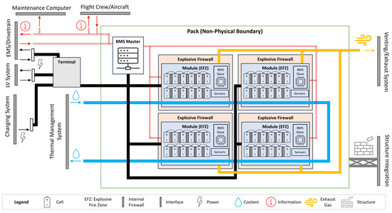
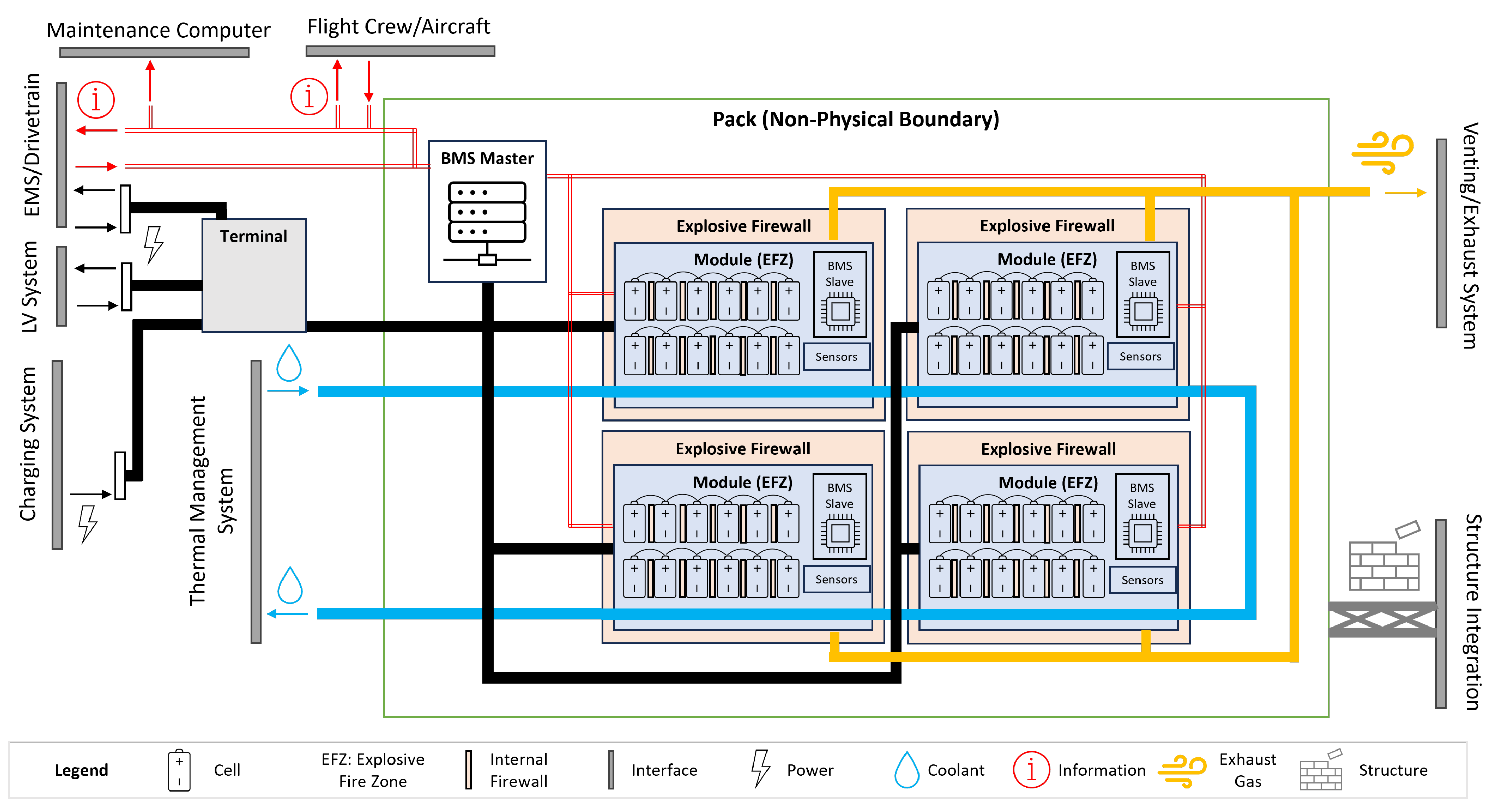
An overview of the system with its interfaces is presented in Figure 1.
Figure 1.
Overview of a battery system architecture for an electric aircraft including interfaces.
2.3. Architecture Definitions and Overview
With an understanding of the functions of the battery system, a set of subsystems is defined. These consist of their own set of functions and physical components and have their own interfaces with other subsystems within the battery system or to external systems mentioned in the previous subsection. These will form the building blocks for our system architecture. The final architecture, together with its interfaces with external systems, is presented in Figure 1. It is important to note that the figure serves illustrational purposes only. Hence, the number of cells and modules, as well as the dimensions of blocks or connections, do not indicate any distinct design choices or relative importance.
For alignment with terminology used within the automotive sector and those used in the MOC for e-VTOL aircraft [18], the terms pack/battery pack for the full battery system and module/battery module for a part of the pack containing the battery cells are used. The terms explosive firewall and explosive fire zone (EFZ) are also proposed by EASA [18] and relate to the area where thermal runaway can occur and what its boundary is.
The battery pack consists of a number of modules that can be connected in parallel or series. At the pack-level, a master-level battery management system (BMS) is present to perform the Sense and Control functionality. This BMS acts as the collector of data from the slave-level BMS incorporated into each module. Furthermore, it can store historical data, identify different SoX and act as the information link (red lines) between the aircraft, flight and/or maintenance crew and the battery system. The pack-level does not need to have a physical boundary to be considered a pack.
Battery modules are defined as physical entities containing a number of electrochemical cells to Store Energy, again connected in series or parallel. A slave-level BMS is present, ensuring cell-balancing and data acquisition. Furthermore, additional sensing equipment is present to monitor module-level characteristics such as temperature and power output parameters. Each module is deemed an EFZ due to the present risk of thermal runaway occurring within the cells. Based on EASA requirements [18], it should be ensured that there is no propagation of thermal runaway outside of the EFZ. Hence, an explosive firewall is surrounding the EFZ and, in this proposed case, the module. This will fulfill the desired Contain, Protect and Isolate functionalities.
In stricter terms, the propagation of thermal runaway from cell-to-cell should also be prevented. This can be achieved by adding internal explosive firewalls between cells [32,33]. However, these safety measures may counteract the required high energy and power density required for electric aviation. This trade-off is important to investigate, given that both sides can lead to an unsuccessful design (either not safe for operation or performance-wise not capable of operating).
Since the requirements mentioned are based on reactive (or lagging) measures and lead to counteracting effects on performance, we aim to investigate the risk associated with aircraft batteries and the possible root causes based on the architecture presented in this section. This knowledge can guide the development of leading safety measures to be implemented in later battery pack designs, as well as be translated into a SoS analysis for currently in-operation or development BPEA.
3. Safety and Abuse
Defining safety in a quantifiable manner is difficult to achieve. In aviation standards, the use of the number of incidents per million or billion flight km (or miles/nautical miles) is common practice. Although a suitable metric, there is no adequate way to predict the validation of the requirements without making assumptions or applying theoretical calculations. Therefore, such metrics are currently evaluated using historical data. This categorizes them as lagging safety metrics [34], as they react to previous events rather than predicting/preventing future events. Metrics capable of doing that are known as leading safety metrics.
In this work, safety is defined as the inverse of abuse/hazards. This is in line with the formulation of safety by the International Civil Aviation Organization (ICAO). A safety risk is defined as “the predicted probability and severity of the consequences or outcomes of a hazard”, in which a hazard is defined as “a condition or an object with the potential to cause or contribute to an aircraft incident or accident” [35]. Other literature on battery safety (e.g., [20,36]) applies the term abuse for these conditions, so the aforementioned definition on safety holds.
3.1. Battery Abuse
Battery abuse can occur in many different ways and can be defined in a number of different ways. Abuses will be classified based on their domain, with five domains explored: thermal, electrical, mechanical, atmospheric, and aging. These will be explored from a macroscopic point of view, focusing on the link between an abusive condition and the resulting failure or deterioration of battery safety. Other literature explores abuses from a microscopic view, linking internal changes to the battery’s structure and chemical composition to an abusive condition and/or a failure mode [36].
During abuse identification, a quantification connection will also be made. Careful attention needs to be paid to the type of battery explored [37]. Depending on the type of battery, abuses, as well as the correlated failure modes, may vary. A more general view, reflecting trends, is adopted here.
3.1.1. Thermal Abuse
As previously mentioned, thermal runaway is not deemed an abuse in itself, but rather as the result of other abuses. Thermal abuse of batteries can occur through either high or low temperatures. Generally, high temperatures can lead to more catastrophic failures [38], while low temperatures influence the long-term safety of the battery [39]. When referring to thermal abuse, the internal cell temperature is of concern. The internal cell temperature is rarely measured in practice, so other measurements, like the cell surface temperature, can act as replacement measurements [40].
3.1.2. Electrical Abuse
Electrical abuse is defined as a noncompliance with the recommended use of the battery [41]. Electrical abuse can occur in many different ways and is well researched [12,42,43]. Over-current and over- or under-voltage are just three such examples. What characterizes electrical abuses is that they are comparably easy to identify and measure.
3.1.3. Atmospheric Conditions
Atmospheric conditions need to be considered as a type of abuse specific to BPEA. During flight, BPEA climb to a high altitude with a low pressure environment. Xie et al. have shown that thermal runaway behavior varies as a function of pressure [44]. The international standard atmosphere (ISA) is defined in ICAO Doc 7488/2. According to this, the pressure experienced by aircraft during cruise flight is ≈20% of the pressure at the ground level. While the low pressure environment influences the failure modes, the change from a low pressure environment during flight to a normal pressure on the ground causes mechanical fatigue [45]. In addition to variations in pressure, atmospheric conditions also entail variations in temperature, with temperatures as low as −56.5 °C above the tropopause.
3.1.4. Mechanical Abuse
Mechanical abuse is the most difficult abuse to identify during use of the battery system. Mechanical abuse is defined as any abuse that alters the physical structure of the battery [41]. As such, several phenomena can be distinguished.
Fatigue is a phenomenon that can be expected to occur due to large thermal gradients during operation. The casing of the battery can be expected to grow and shrink with changes in temperature. Similarly, batteries experience variations in pressure due to discharging and charging, as well as the pressure differences experienced due to operating the aircraft at high altitudes.
Deformation can occur in a variety of ways: e.g., bending, crimping, denting, perforation or shearing [20]. In nominal operation, the battery is not expected to experience any of these. However, accidents and incidents occur and need to be considered for the overall safety of the battery. Within this work, crashes are excluded (focus on continued safe flight and landing), yet it is important to investigate the effect of crash landings on battery systems, such as the work done by Camus and Halbout [46]. A collision with a small object that does not alter the aerodynamic performance of the aircraft may cause damage to the battery system. It may not always be desired to immediately replace that part if the resulting safety implications are still within safe limits. The overall safety may already be deteriorated, meaning that further abuse can create an unsafe situation; even if under normal operation, the same level of abuse would be no cause for concern.
Vibrations are known to influence the performance and safety of the battery at a macroscopic level [47,48]. Research exploring the underlying microscopic effects does exist. Li et al. [49] demonstrate that the internal resistance of the battery varies with vibration. Further, they show that vibrations cause an uneven heat distribution in the battery, increasing the vibration’s impact on the safety of the battery.
3.1.5. Aging
Battery aging is a well-established phenomenon [50]. Aging does not directly deteriorate the safety of the battery, instead affecting the battery’s performance. Two types of aging have been identified: cyclic aging and calendar aging [51]. For aviation-specific purposes, the cyclic aging is of great importance due to the number of expected flight cycles influencing the usability of batteries, as well as defining the financial feasibility for airlines.
3.2. State of Safety
Battery metrics are often given not just as the output of a direct measurement, but also in so-called states. Direct measurements like output current, terminal voltage or surface temperature are important measurements; these states, however, provide further information about the battery. State of charge (SoC) is one of the most well-known states, describing the remaining capacity of the battery during use. Similarly, other states describe secondary characteristics of the battery. The State of Health (SoH) describes the current battery performance ceiling compared to its initial performance ceiling. While the SoH is often referred to as describing the safety of the battery, only degradations in cell performance are captured, whereas other safety-deteriorating abuses are not captured. The goal of these states is to provide easily-accessible and easily-understood information to the user.
The State of Safety (SoS) describes the ‘remaining’ safety of the battery. Safety is commonly defined as the inverse of abuse, and is treated like an inherent system state akin to terminal voltage or surface temperature. The SoS is given as a percentage of the remaining safety, with low percentages indicating a low safety, i.e., a greater chance of subsequent failure.
Cabrera-Castillo et al. [24] provide a mathematical description of the SoS based on a number of different abuse characteristics:
In order to determine the SoS, every abuse (k) needs to be characterized individually. Taking terminal voltage as an example, it is obvious that not all values automatically constitute an abuse condition. Equation (1) returns a percentage of safety given a current value of abuse k. defines the acceptable limit of where an increase of would lead to an unsafe condition associated with the relative safety at that level of abuse. Similarly, defines the value where there is no impact on the safety of the battery. , and are in the units associated with abuse k, with the units ultimately canceling to yield a percentage. The resulting functions for every abuse are multiplied to yield the overall SoS.
There are differing theories on how to define the overall safety threshold. Cabrera-Castillo et al. [24] define the overall threshold based on a common value of . Zou and Li [52] use a different method based on potential fields to define safe operating zones. They define the safety thresholds based on the average value of and add more granularity to the zone classified as safe by Cabrera-Castillo et al.
All of the abuses identified have a direct or indirect impact on the SoS as defined in Equation (1) [25].
3.3. Review of SoS Literature
The SoS has been explored in the literature, both directly (via SoS definitions and estimations) and indirectly (estimating safety or abuse conditions of batteries). In this section, a review is presented, with Table 1 providing an overview of the parameters used in the respective studies. Studies were selected from the Scopus database, and decisions were based on the presence of the terms State of Safety, Battery Failure Modes, or Battery Abuse Conditions (along with synonyms) within the title or abstract, ensuring the presence of papers concerning the definition of these parameters. Other valuable work that was included focuses on batteries for specific use in aviation.
Table 1.
Comparison of the parameters used by studies investigating the safety of batteries. Parameters are grouped by domain.
Wang et al. [53] has developed a procedure to assess battery safety. Importantly, this provides a prediction about the safety risks associated with a specific battery rather than assessing the safety during use. On the other hand, Moon et al. [54] targets the operational condition by assessing the safety of batteries in electric vehicle crashes. The assessment is performed by measuring the deviation from mean (standard deviation) of the cells. However, this system is only reliable if only one cell features an anomaly.
Using a Bayesian network, Sarkar et al. [55] have expanded the definition of safe operating area of batteries. They identify failure mechanisms and health indicators of cylindrical lithium-ion batteries by analyzing the electrical, thermal and mechanical domain. R. Wenzel [56] uses the method described in [24] to determine the SoS of a stationary battery buffer over a longer period of time. The work identifies critical points in time as well as the abuses that caused them.
In a work focusing on the safety of future generation batteries (solid-state and sodium-sulphite-based cells), Yang et al. [57] highlight the need for understanding the abuse tolerance of cells. Gu et al. [58] have identified thermal runaway behavior by performing physical tests (overheating and overcharging) on Li-ion cells. Their work focuses on creating early-warning methods for thermal runaway during use. They have reported that the SoS is not linearly dependent on a single parameter but an integrated result of all factors mentioned in their work highlighted in Table 1, thus proving the need for new assessment methods.
Since the SoS can be used in a similar manner to other SoX, Hu et al. [59] have performed a concise, understandable overview of existing methods, key issues, technical challenges, and future trends of the battery state estimation domain. They present the SoS as a probability function containing all abuses (including severity and likelihood) as sub-functions, using the product as the final SoS determination. Furthermore, they highlight the need for accurate quantification of abuse conditions.
Research regarding the SoS of batteries for use in aviation has also been performed. Yang et al. [60] investigated the risks associated with Li-ion batteries for aviation, aiming at mitigation methods. Hu et al. [61] performed physical tests on Li-ion cells, highlighting the risks associated with using these as propulsion batteries in aviation. Their work finds that the unique risk associated with aviation is the use of cells with very high energy densities. With regard to TR, the SoC of cells in combination with the operating temperature proved to be the most influential while performing experimental analysis. At high SoC and ambient temperature, TR onset was the shortest and the TR phenomena themselves the most intense by reaching the highest peak temperatures and associated smoke/gas release in mass loss.
Other literature also reports that the SoC of the cells has the most influence on the heat release measured during TR, as discussed by Chen et al. [13] and Huang et al. [14]. Furthermore, Chen et al. measured the effects of external pressure on TR effects by triggering cells at different altitudes. It is reported that at higher environmental pressure (ground-level operation), TR effects were significantly more severe than at lower environmental pressure (still below flight level). Hence, flight level environmental pressures have been proven beneficial for TR severity.
4. Findings
We have defined a scope for the SUD and identified abuses affecting the battery system. In the following, we will identify risks resulting from the identified abuses, the system structure and the system operation. We will group these risks based on their cause: flight profile, component failures and exceptional events. Risks due to the flight profile follow the same structure as Section 3.1, while risks due to failures follow the structure presented in Section 2.
4.1. Risks Due to the Flight Profile
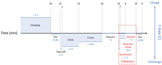
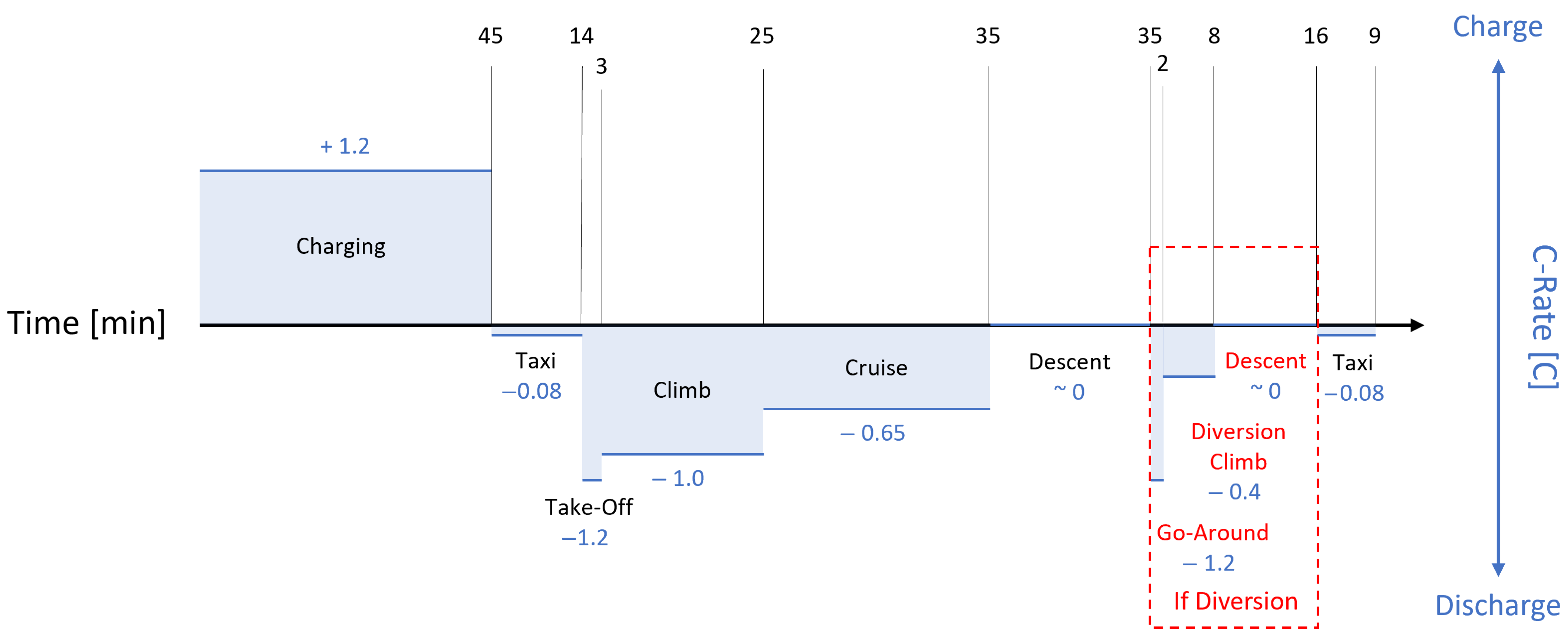
All aircraft follow a similar flight profile, which encompasses taxiing, take-off, climb, cruise, descent, approach and landing as the primary phases during a nominal flight. Additional phases detailed in some of the literature add further granularity based on operational requirements. For the technical analysis of each phase, only the primary phases are relevant. Commonly, a failed landing attempt is included in the flight profile, encompassing go-around, diversion climb, diversion and loiter as a well as a second descent, approach and landing sequence. An overview of such a flight profile, along with relevant charge and discharge profiles, is shown in Figure 2.
Figure 2.
Overview of a flight profile for an electric aircraft including charge/discharge rates—with partial use of data from [6].
Part of the C-rate data in the figure comes from assumptions made in [6], with the addition of taxiing phases. Taxiing at Schiphol Airport in the Netherlands has been taken as a use-case. Average taxi-times at that airport are 14 min for outbound and 9 min for inbound traffic [62]. Energy usage during taxiing is estimated at 7% of the take-off power, similar to kerosene-powered aircraft [63].
In order to enable a diversion to an alternative airport due to unforeseen closure of the primary airport, conventional aircraft carry a fuel reserve. BPEA have been proposed with a secondary propulsion system to cover the diversion phase. They nonetheless require the EESS to provide enough power to cover the go-around and initial diversion climb [5]. This is the most critical phase of the flight profile, as batteries that are low on charge (and thus voltage) have to deliver similar power to nearly fully charged batteries at take-off. This can lead to current spikes up to 25% higher than during normal take-off [6].
All of the presented risks will affect every single flight of the BPEA and therefore require special attention and consideration in the early design stages. They pose monitoring requirements as defined in Section 3.1 to be quantified during flight, as well as mitigation techniques built into the design.
- Atmospheric Conditions. The primary contribution to risks associated with the flight profile are atmospheric abuses identified in Section 3.1. In operation, BPEA experience drastic pressure variations, from 0.2 bar in flight to 1 bar at sea level. This imposes structural requirements, not seen in electric vehicles, for the physical structure of the battery at both the pack and module level. Batteries will have to be treated as pressurized containers, similarly as, e.g., the fuselage (aircraft design specifications CS-25.365 [64]).
- Electrical Abuse. The electrical load on the batteries is greatest during take-off and go-around. During both phases, the pilots demand maximum thrust from the engines to accelerate the aircraft from a landing speed to a take-off speed. For BPEA, the go-around is the more critical of the two phases, as it is characterized by the same power demand at much lower SoC [65]. It is therefore paramount to consider the go-around as the most demanding phase—in terms of electrical abuse—of nominal operation of the BPEA. A capable BMS is needed to ensure the battery does not exceed safe operating thresholds during the go-around. Abubakar et al. [27] also propose the use of a hybrid system during take-off and go-around to limit the electrical and thermal stress on the battery system.
- Thermal Abuse. As defined in the international standard atmosphere (ISA), temperatures in flight vary between the local temperature on the ground and −56.5 °C. Proper thermal management of the EESS is necessary to contain internal high temperatures, as well as protect the batteries from extremely low external temperatures. Automotive certification is for temperatures down to −40 °C [66], and the demands for the thermal management system of BPEA are thus much greater.
- Mechanical Abuse. Vibrations occur regularly in aircraft (ISO 7137 & RTCA DO-160). Compared to other forms of electric mobility, the vibration profile may differ—also depending on the positioning of the EESS within the aircraft. While the effect of vibrations on Lithium-Ion batteries is studied, the specific effects associated with the vibration profile in aircraft is not. Therefore the effects of vibrations on the performance and safety of the EESS are unknown. Vibrations can cause fatigue-like damages, as well as affect the performance characteristics of the battery cells [5].
- Aging. Another unknown risk is associated with the aging of the battery cells due to the flight profile. At present, it is unknown what effects the rapid and correlated changes in temperature and pressure have on the aging of the battery cells. Battery aging due to cyclic charging and discharging is well explored in the automotive space [50]; however, the presented flight profile in Figure 2 can lead to a different course of aging. Both effects need to be considered when choosing a battery chemistry and structure to ensure a successful final product that is both safe and meets performance requirements. Additionally, due to the high number of daily flights for short range aircraft, some batteries used in proposed BPEA are expected to last 3–5 months [65], posing an economic risk for operators.
4.2. Risks Due to Failures
Failures within the interfaces have been briefly hinted at in Section 2. We consider failures outside of the system boundary of the EESS to be contributors to safety risks for the EESS. Failures within the EESS are considered the result of an abuse as defined in Section 3.1, and therefore not mentioned here. Failures at all four types of interfaces defined in Figure 1 are explored: electrical, mechanical, hydraulic, information.
- Electrical Interface. Failures in systems associated with the electrical interfaces of the EESS can lead to exceptional and unexpected sudden changes in electrical load on the batteries. It is likely that the BMS on both the master and slave levels are well-equipped to protect the battery pack from resultant damages. Nonetheless, the designer of a BPEA needs to be aware of the propagation of external failures to the batteries. One such failure is an external short-circuit in the high-voltage system.In electric vehicles, the BMS is not directly powered by the batteries it supervises, but rather connected to a low-voltage battery, also used in conventionally powered vehicles [67]. Given the lack of currently existing BPEA, we assume that a similar approach may be used. A failure of that battery can in theory render the entire EESS inoperational in an instant.
- Mechanical Interfaces. Analogous to failures propagating along the electrical interfaces of the EESS, failures can propagate along mechanical interfaces. Mechanical damage to any part of an aircraft is undesired, but also very common. Any aircraft flying today will have mechanical damages of some kind that are monitored until the next scheduled maintenance. Mechanical damages outside the EESS can cause additional loads on the structure of the EESS or damage components of the EESS. The explosive firewall can be compromised leading, to neighboring EFZs to become joined together.Mechanical damages can also impact pressure propagation paths used in the exhaust system for venting. This may lead to higher-than-normal internal pressures of the battery modules and/or cells.
- Hydraulic Interfaces. External failures of a hydraulic cooling system can lead to a direct failure of the thermal management system, with overheating of the batteries and subsequent thermal runaway and fires being likely consequences.
- Information Interfaces. A disruption of the flow of information results in the system not being able to determine its own SoS, preventing the BMS from working properly. Similarly, a disruption of the flow of information between pilot and aircraft or pilot and maintenance crew can lead to poor decision making by the pilot, or maintenance procedures not executed in a timely manner. All these can lead to not just failures of the EESS, but catastrophic failures of the entire aircraft.
4.3. Risks Due to Exceptional Events
Exceptional events are events that can not be expected to occur due to normal wear and damages or due to the characteristics of operation. Within aviation standards, these are usually taken out of the requirements and a focus is put on a continued safe flight and landing. This is aimed at ensuring that a mid-flight failure can be resolved by finding a suitable place to land and not harm any passengers or crew on board. As such, we focus on small accidents that regularly occur with aircraft on the ground, bird strikes or similar events.
All these events cause damage beyond the normal wear of the aircraft. Due to their exceptional nature, it is difficult to further classify these events. However, some notable examples are piercing of protective structures due to debris strikes that propagate as mechanical damage to the EESS, compromising its structure. Concorde was removed from operation following a crash that involved vibrations induced by a debris strike that resulted in further failures [68].
Accidents are not always reported immediately or reported at all [69]. For BPEA, just as much as for conventional aircraft, this has significant safety implications, which should never be neglected by operators.
5. Discussion
This work investigates the safety risks inherent to the use of high energy density Li-Ion pouch cells within aviation. Two main purposes are behind this research: (1) identifying risk factors and how to reduce their impact within the development phase, and (2) identifying quantifiable/measurable factors to take into account in a State of Safety derivation. The latter can be used in-operation to inform the flight crew about the behavior of the battery system. Both methods were evaluated based on a comparison with ground-based electric vehicles, as well as to the incidents related to the Boeing 787 Dreamliners.
Risks found in aviation battery systems show alignment with those found in ground vehicle traction batteries. Similar failure modes are—as expected—recognizable and knowledge regarding their impact, and possible mitigation methods can be used in aviation battery system design. Similar to the discussed literature, failure modes can be grouped into normal and abusive/abnormal operation, or by category: environmental, thermal, electrical, chemical or mechanical. Within the SoS literature, it was found that parameters in the aging and indirect domains were also often cited as risk factors. Furthermore, it was found that the safety of aircraft batteries is a complex combination of these abuse conditions and cannot be seen as a linear relation with a single abuse condition. Hence, this work can act as a baseline for further evaluation/calculation of the SoS.
The atmospheric conditions are more influential for aviation batteries than for vehicle batteries. Lower pressures are found to decrease the impact of thermal runaway events by increasing the triggering time and reducing the intensity [44] and heat release [13]. Hence, when operating at higher flight levels, environmental pressure can have a positive influence. However, low operating temperatures and possible high humidity levels can lead to ice formation when not isolated properly. Second to this, the low operating temperatures fall out of the certification range in use for vehicles, which will require further attention.
It is unsure to what extent the flight cycle will have an effect on the cycle life of the battery cells. Compared to vehicles in normal operation, the take-off phase is more sustained (high discharge rate). More importantly, the possible go-around take-off requires similar power outputs at low SoC [6]. In severe cases, this can lead to an overdischarge of the battery, causing a failure. Ensuring adequate knowledge regarding the SoC is important before such a maneuver is performed. Careful flight mission planning and accurate BMS systems capable of estimating the SoC are key. The addition of range-extenders can also be seen as beneficial.
Within the flight, the aircraft will endure vibrations and movement in all directions. These can have a similar effect on batteries as vibrations experienced in ground vehicles. However, based on the location of the battery system within the aircraft, more specific vibrations can be experienced by the cells/battery system. This is especially the case when batteries are placed in the wing of an aircraft, as these go through different harmonic vibrations within a flight cycle. Appropriate measures should be taken within the design—either within the module design, or within the interface between battery system and aircraft structure—, such as weak leaf springs acting as dampers to mitigate the vibration effects on the cells themselves. The specifics regarding the vibrations and their effects need to be determined during the design of an aircraft, as these are dependent on the wing length and aspect ratio.
Failure propagation throughout the battery system, or through interface barriers between it and other systems is also a key risk factor. A thermal runaway in one module can lead to an increase in temperature of the cooling fluid passing through it, which can lead to an overheating situation in an adjacent module (assuming an in-series TMS). Sudden power spikes or losses can lead to failures in the electrical systems. Structural failures within the battery system can lead to failures of the aircraft structure, depending on its connection.
In the report [16] regarding the Boeing 787 Dreamliner incidents, a few factors were highlighted: cell-level failures, insufficient guidance for assumptions in safety assessments and insufficient guidance during the certification process. Within this work, we explored cell-level failures and how failures can propagate throughout an aircraft battery system. This allows for a better understanding of how these can be mitigated within the design.
Even though we did not have access to the direct communication between governing bodies and aircraft manufacturers, publicly available standards and regulations show little presence of relevant information for the use of batteries as main energy storage within an aircraft. Available standards and MOC documents are open for peer feedback from the industry, which highlights the importance of collaboration between the aviation industry and regulatory organizations for this novel application. Our work can provide insight into how failures can be mitigated through design standards/requirements.
This work was aimed at connecting failure modes within an aircraft propulsion battery to components or interfaces of the battery system. The presented architecture provides a general overview and can be used as a guideline for further evaluation and development. Component-level design decisions will highly influence the risks associated with the mentioned failure modes and it is important to note that a quantitative analysis should be performed based on the design. A quantitative analysis of the failure modes and their associated risks should also be performed to act as input for the calculation of the State of Safety. This work provides an overview of which failure modes can be included in such a determination.
6. Conclusions and Future Work
Aviation-specific safety standards and regulations are lacking in comparison to ones aimed at electric vehicles. Hence, the aim of this work was to identify the differences between both applications and highlight where risk factors might differ and whether other failure modes are present within aviation batteries. This leads to three main differences between aviation and ground vehicles: the influence of atmospheric conditions, the influence of the flight profile and exerted vibrations.
Some limitations regarding this work also form the basis for the recommended future work, mainly considering the gathering of experimental data with respect to the effect of an aircraft flight profile on the aging of battery cells. This can be implemented by cycling cells along a proposed flight profile consisting of charging, taxiing, take-off, climb, cruise, descent, approach, and landing as the primary phases during a nominal flight. Additionally, the inclusion of separate tests regarding go-around conditions (low SoC, high power demand) is recommended.
This work focuses on the risk associated with high-energy Li-Ion cells. Chemistry and cell-type selection have proven to have significant influence on the risks associated with propulsion batteries. Hence, a trend-based, more generic view has been applied within this work. Whereas this does align with the other literature, application requires a more detailed evaluation (e.g., failure mode effect analysis or fault hazard analysis) tailored to the chosen cell type and chemistry.
For inclusion of in-flight SoS calculations, a method for quantifying safe and unsafe operating zones of parameters has to be found. These factors should have an accompanying weighing factor to express their influence on the total SoS of the system. The proposal presented here is done in the thesis of J. Dalitz [25]. As mentioned before, the gathering of specific data associated with the chosen cell type is of great importance for a reliable calculation.
Author Contributions
Conceptualization, R.v.Z., J.D. and P.V.; Architecture Design, R.v.Z.; Abuse Condition Analysis, J.D.; Writing—original draft preparation, R.v.Z. and J.D.; Writing—review and editing, R.v.Z., J.D. and P.V.; Supervision, P.V. All authors have read and agreed to the published version of the manuscript.
Funding
This research received no external funding.
Data Availability Statement
No new data were created or analyzed in this study. Data sharing is not applicable to this article.
Conflicts of Interest
The authors declare no conflicts of interest.
Abbreviations
The following abbreviations are used in this manuscript:
| BMS | Battery Management System |
| BPEA | Battery-Powered Electric Aircraft |
| EASA | European Union Aviation Safety Agency |
| EESS | Electrical Energy Storage System |
| EFZ | Explosive Fire Zone |
| EMS | Energy Management System |
| e-VTOL | Electric Vertical Take-Off and Landing Aircraft |
| FAA | Federal Aviation Administration |
| ICAO | International Civil Aviation Organization |
| ISA | International Standard Atmosphere |
| MOC | Means of Compliance |
| NTSB | National Transportation Safety Board |
| SoC | State of Charge |
| SoH | State of Health |
| SoS | State of Safety |
| SoX | State of X |
| SUD | System Under Design |
| TMS | Thermal Management System |
| TR | Thermal Runaway |
References
- Viswanathan, V.; Epstein, A.H.; Chiang, Y.M.; Takeuchi, E.; Bradley, M.; Langford, J.; Winter, M. The challenges and opportunities of battery-powered flight. Nature 2022, 601, 519–525. [Google Scholar] [CrossRef] [Scilit]
- Pipistrel. Velis Electro. 2025. Available online: https://www.pipistrel-aircraft.com/products/velis-electro/ (accessed on 3 June 2025).
- Archer Aviation. Introducing Maker. Available online: https://www.archer.com/maker (accessed on 11 June 2025).
- Maeve Aerospace BV. Maeve Jet. Available online: https://maeve.aero/maeve-jet (accessed on 11 June 2025).
- de Vries, R.; Wolleswinkel, R.E.; Hoogreef, M.; Vos, R. A New Perspective on Battery-Electric Aviation, Part II: Conceptual Design of a 90-Seater. In AIAA SCITECH 2024 Forum; AIAA SciTech Forum; American Institute of Aeronautics and Astronautics: Orlando, FL, USA, 2024. [Google Scholar] [CrossRef] [Scilit]
- de Vries, R.; Wolleswinkel, R.E.; Jacobson, D.R.; Bonnema, M.; Thiede, S. Battery Performance Metrics for Large Electric Passenger Aircraft. In Proceedings of the 34th Congress of the International Council of the Aeronautical Sciences (ICAS), Florence, Italy, 9–13 September 2024. [Google Scholar]
- Kühnelt, H.; Mastropierro, F.; Zhang, N.; Toghyani, S.; Krewer, U. Are batteries fit for hybrid-electric regional aircraft? J. Phys. Conf. Ser. 2023, 2526, 012026. [Google Scholar] [CrossRef] [Scilit]
- Feng, X.; Ren, D.; He, X.; Ouyang, M. Mitigating Thermal Runaway of Lithium-Ion Batteries. Joule 2020, 4, 743–770. [Google Scholar] [CrossRef] [Scilit]
- Amano, K.; Hahn, S.K.; Tschirschwitz, R.; Rappsilber, T.; Krause, U. An Experimental Investigation of Thermal Runaway and Gas Release of NMC Lithium-Ion Pouch Batteries Depending on the State of Charge Level. Batteries 2022, 8, 41. [Google Scholar] [CrossRef] [Scilit]
- Dong, Y.; Meng, J.; Sun, X.; Zhao, P.; Sun, P.; Zheng, B. Experimental Study on Effects of Triggering Modes on Thermal Runaway Characteristics of Lithium-Ion Battery. World Electr. Veh. J. 2023, 14, 270. [Google Scholar] [CrossRef] [Scilit]
- European Union Aviation Safety Agency. Mitigation of Flight Deck Fires Originating from Lithium Batteries That Are Not Part of the Aircraft Design. 2022. Available online: https://www.easa.europa.eu/en/downloads/136404/en (accessed on 7 November 2025).
- Wang, D.; Zheng, L.; Li, X.; Du, G.; Zhang, Z.; Feng, Y.; Jia, L.; Dai, Z. Effects of Overdischarge Rate on Thermal Runaway of NCM811 Li-Ion Batteries. Energies 2020, 13, 3885. [Google Scholar] [CrossRef] [Scilit]
- Chen, M.; Ouyang, D.; Weng, J.; Liu, J.; Wang, J. Environmental pressure effects on thermal runaway and fire behaviors of lithium-ion battery with different cathodes and state of charge. Process Saf. Environ. Prot. 2019, 130, 250–256. [Google Scholar] [CrossRef] [Scilit]
- Huang, Y.; Zhao, Y.; Bai, W.; Cao, Y.; Xu, W.; Shen, X.; Wang, Z. Study on the influence of high rate charge and discharge on thermal runaway behavior of lithium-ion battery. Process Saf. Environ. Prot. 2024, 191, 1483–1494. [Google Scholar] [CrossRef] [Scilit]
- Williard, N.; He, W.; Hendricks, C.; Pecht, M. Lessons Learned from the 787 Dreamliner Issue on Lithium-Ion Battery Reliability. Energies 2013, 6, 4682–4695. [Google Scholar] [CrossRef] [Scilit]
- National Transportation Safety Board. Auxiliary Power Unit Battery Fire, Japan Airlines Boeing 787-8, JA829J, Boston, Massachusetts, January 7, 2013; Technical Report NTSB/AIR-14/01; National Transportation Safety Board: Washington, DC, USA, 2014.
- Federal Aviation Administration. Proposed Special Conditions: Boeing Model 787-8 Airplane; Lithium Ion Battery Installation; Technical Report Docket No. NM375; Federal Aviation Administration (FAA): Washington, DC, USA, 2007.
- European Union Aviation Safety Agency. Means of Compliance with the Special Condition VTOL; European Union Aviation Safety Agency: Cologne, Germany, 2021.
- Federal Aviation Administration. Guidance on Testing and Installation of Rechargeable Lithium Battery and Battery Systems on Aircraft; Federal Aviation Administration: Washington, DC, USA, 2015.
- Ruiz, V.; Pfrang, A.; Kriston, A.; Omar, N.; Van den Bossche, P.; Boon-Brett, L. A review of international abuse testing standards and regulations for lithium ion batteries in electric and hybrid electric vehicles. Renew. Sustain. Energy Rev. 2018, 81, 1427–1452. [Google Scholar] [CrossRef] [Scilit]
- Gandoman, F.H.; Jaguemont, J.; Goutam, S.; Gopalakrishnan, R.; Firouz, Y.; Kalogiannis, T.; Omar, N.; Van Mierlo, J. Concept of reliability and safety assessment of lithium-ion batteries in electric vehicles: Basics, progress, and challenges. Appl. Energy 2019, 251, 113343. [Google Scholar] [CrossRef] [Scilit]
- Evshchik, E.; Shikhovtseva, A.; Kolmakov, V.; Bugaev, V.; Valeev, R.; Voropaev, V.; Levchenko, A. Lithium-ion batteries for space applications in low earth orbits: Promising Technologies and testing methods. Appl. Energy 2026, 406, 127266. [Google Scholar] [CrossRef] [Scilit]
- Manzo, M.A.; Brewer, J.C.; Bugga, R.V.; Darcy, E.C.; Jeevarajan, J.A.; McKissock, B.I.; Schmitz, P.C. NASA Aerospace Flight Battery Program: Generic Safety, Handling and Qualification Guidelines for Lithium-Ion (Li-Ion) Batteries; Availability of Source Materials for Lithium-Ion (Li-Ion) Batteries; Maintaining Technical Communications Related to Aerospace Batteries (NASA Aerospace Battery Workshop); Technical Report; NASA: Washington, DC, USA, 2010.
- Cabrera-Castillo, E.; Niedermeier, F.; Jossen, A. Calculation of the state of safety (SOS) for lithium ion batteries. J. Power Sources 2016, 324, 509–520. [Google Scholar] [CrossRef] [Scilit]
- Dalitz, J. State of Safety of Electric Aircraft Batteries. Bachelor’s Thesis, University of Twente, Enschede, The Netherlands, 2025. [Google Scholar]
- Bingham, T.; Moore, M.; De Caux, T.; Pacino, M. Design, build, test and flight of the world’s fastest electric aircraft. IET Electr. Syst. Transp. 2022, 12, 380–402. [Google Scholar] [CrossRef] [Scilit]
- Abubakar, A.; Klumpner, C.; Wheeler, P. Optimal Design of Energy Storage System for Electric Aircraft. In Proceedings of the 2025 Energy Conversion Congress & Expo Europe (ECCE Europe), Birmingham, UK, 1–4 September 2025; pp. 1–6. [Google Scholar] [CrossRef] [Scilit]
- BETA Technologies. Aircraft. 2025. Available online: https://beta.team/aircraft (accessed on 15 December 2025).
- van Zijl, R.; Wassens, S.A.; Reyes Garcia, J.R.; Bonnema, G.M. Enabling Battery-Powered Commercial Aviation: Developing a System Architecture for a Multi-MW Charging System. In Proceedings of the 2025 IEEE International Symposium on Systems Engineering (ISSE), Palaiseau, France, 28–30 October 2025; pp. 1–8. [Google Scholar] [CrossRef] [Scilit]
- Liang, Y.; Mouli, G.R.C.; Bauer, P. Charging Technology for Electric Aircraft: State of the Art, Trends, and Challenges. IEEE Trans. Transp. Electrif. 2024, 10, 6761–6788. [Google Scholar] [CrossRef] [Scilit]
- Battery Standards Testing Committee. Electric-Drive Battery Pack System: Functional Guidelines; Technical Report; SAE International: Warrendale, PA, USA, 2021. [Google Scholar] [CrossRef] [Scilit]
- Yang, C.; Sunderlin, N.; Wang, W.; Churchill, C.; Keyser, M. Compressible battery foams to prevent cascading thermal runaway in Li-ion pouch batteries. J. Power Sources 2022, 541, 231666. [Google Scholar] [CrossRef] [Scilit]
- Li, L.; Xu, C.; Chang, R.; Yang, C.; Jia, C.; Wang, L.; Song, J.; Li, Z.; Zhang, F.; Fang, B.; et al. Thermal-responsive, super-strong, ultrathin firewalls for quenching thermal runaway in high-energy battery modules. Energy Storage Mater. 2021, 40, 329–336. [Google Scholar] [CrossRef] [Scilit]
- de Boer, R.; Karanikas, N.; Steffen, K.; Piric, S.; Roelen, A.; Aalst, R.; Vardy, A.; Plioutsias, A.; Papanikou, M. Measuring Safety in Aviation: Developing Metrics for Safety Management Systems; Aviation Academy, Amsterdam University of Applied Sciences: Amsterdam, The Netherlands, 2020; ISBN 9789492644206. [Google Scholar]
- ICAO. Global Aviation Safety Plan 2026–2028; Technical Report Doc 10004; International Civil Aviation Organization: Montréal, QC, Canada, 2025. [Google Scholar]
- Lalinde, I.; Berrueta, A.; Arza, J.; Sanchis, P.; Ursúa, A. On the characterization of lithium-ion batteries under overtemperature and overcharge conditions: Identification of abuse areas and experimental validation. Appl. Energy 2024, 354, 122205. [Google Scholar] [CrossRef] [Scilit]
- Howard, G.E.; Buston, J.E.H.; Gill, J.; Goddard, S.L.; Mellor, J.W.; Reeve, P.A.P. The Effects of Cell Chemistry, State of Charge, and Abuse Method on Gas Generation in Li-Ion Cell Failure. Batteries 2025, 11, 320. [Google Scholar] [CrossRef] [Scilit]
- Jia, L.; Wang, D.; Yin, T.; Li, X.; Li, L.; Dai, Z.; Zheng, L. Experimental Study on Thermal-Induced Runaway in High Nickel Ternary Batteries. ACS Omega 2022, 7, 14562–14570. [Google Scholar] [CrossRef] [Scilit]
- Kong, D.; Zhao, H.; Ping, P.; Zhang, Y.; Wang, G. Effect of low temperature on thermal runaway and fire behaviors of 18650 lithium-ion battery: A comprehensive experimental study. Process Saf. Environ. Prot. 2023, 174, 448–459. [Google Scholar] [CrossRef] [Scilit]
- Ludwig, S.; Steinhardt, M.; Jossen, A. Determination of Internal Temperature Differences for Various Cylindrical Lithium-Ion Batteries Using a Pulse Resistance Approach. Batteries 2022, 8, 60. [Google Scholar] [CrossRef] [Scilit]
- Jaguemont, J.; Bardé, F. A critical review of lithium-ion battery safety testing and standards. Appl. Therm. Eng. 2023, 231, 121014. [Google Scholar] [CrossRef] [Scilit]
- Gui, Q.; Jin, B.; Liu, P.; Yu, K.; Zhang, J.; Mao, L. Revealing the Hazard of Mild Electrical Abuse on the Safety Characteristics of NaNi1/3Fe1/3Mn1/3O2 Cathode Sodium-Ion Battery. Adv. Sci. 2025, 12, 2501649. [Google Scholar] [CrossRef] [Scilit] [PubMed]
- Menye, J.S.; Camara, M.B.; Dakyo, B. Lithium Battery Degradation and Failure Mechanisms: A State-of-the-Art Review. Energies 2025, 18, 342. [Google Scholar] [CrossRef] [Scilit]
- Xie, S.; Ren, L.; Gong, Y.; Li, M.; Chen, X. Effect of Charging/Discharging Rate on the Thermal Runaway Characteristics of Lithium-Ion Batteries in Low Pressure. J. Electrochem. Soc. 2020, 167, 140503. [Google Scholar] [CrossRef] [Scilit]
- Great Britain Ministry of Transport and Civil Aviation. Civil Aircraft Accident: Report of the Court of Inquiry into the Accidents to Comet G-ALYP on 10th January, 1954 and Comet G-ALYY on 8th April, 1954; Technical Report; Great Britain Ministry of Transport and Civil Aviation: London, UK, 1955.
- Camus, J.; Halbout, S. Crash Testing Lithium-Ion Battery for Helicopters. 2024. Available online: https://openscience.isae-supaero.fr/Default/doc/SYRACUSE/16134/crash-testing-lithium-ion-battery-for-helicopters (accessed on 18 February 2026).
- Lee, P.Y.; Park, S.; Cho, I.; Kim, J. Vibration-based degradation effect in rechargeable lithium ion batteries having different cathode materials for railway vehicle application. Eng. Fail. Anal. 2021, 124, 105334. [Google Scholar] [CrossRef] [Scilit]
- Sabeel, K.; Al-Greer, M.; Bashir, I. Advancements in Vibration Testing: Effects on Thermal Performance and Degradation of Modern Batteries. Batteries 2025, 11, 82. [Google Scholar] [CrossRef] [Scilit]
- Li, Y.; Zhou, L.; Jiang, H.; Zhang, Q.; Zhang, S.; Zhu, X.; Meng, W.; Qiu, J.; Hu, H.; Ming, H. Vibration induced performance degradation on LiNi0.5Co0.2Mn0.3O2/graphite lithium-ion battery. J. Energy Storage 2025, 132, 117700. [Google Scholar] [CrossRef] [Scilit]
- Yarimca, G.; Cetkin, E.; Yarimca, G.; Cetkin, E. Review of Cell Level Battery (Calendar and Cycling) Aging Models: Electric Vehicles. Batteries 2024, 10, 374. [Google Scholar] [CrossRef] [Scilit]
- Michelini, E.; Höschele, P.; Ellersdorfer, C.; Moser, J. Impact of Prolonged Electrochemical Cycling on Health Indicators of Aged Lithium-Ion Batteries for a Second-Life Use. IEEE Access 2024, 12, 193707–193716. [Google Scholar] [CrossRef] [Scilit]
- Zou, W.; Li, J. Quantitative assessment approach of fuel cell operating state of safety based on potential field method. Renew. Energy 2025, 238, 12782. [Google Scholar] [CrossRef] [Scilit]
- Wang, M.; Wu, S.; Chen, Y.; Wang, S.; Chen, H.; Luan, W. Quantitative safety assessment of lithium-ion batteries: Integrating abuse risks and intrinsic safety. J. Power Sources 2025, 640, 236789. [Google Scholar] [CrossRef] [Scilit]
- Moon, J.; Vennam, G.; Tanvir, T.R.; Rahn, C.D. State of Safety Assessment in Electric Vehicle Battery Packs. In Proceedings of the 2024 IEEE Vehicle Power and Propulsion Conference (VPPC), Washington, DC, USA, 7–10 October 2024; pp. 1–5. [Google Scholar] [CrossRef] [Scilit]
- Sarkar, S.; Swamy, D.; Amin, M.T.; El-Halwagi, M.; Khan, F. Safer operating areas (SOA) of cylindrical lithium-ion battery—A probabilistic approach. Process Saf. Environ. Prot. 2024, 190, 708–725. [Google Scholar] [CrossRef] [Scilit]
- Wenzel, R. State-of-Safety (SoS) Data-Driven Assessment for Utility-Scale Lithium- Ion Operating BESS. Ph.D. Thesis, KTH Royal Institute of Technology, Stockholm, Sweden, 2023. [Google Scholar]
- Yang, C.; Singh, A.; Pu, X.; Mallarapu, A.; Smith, K.; Keyser, M.; Haberman, M.R.; Khani, H.; Misztal, P.; Spray, R.; et al. Addressing the safety of next-generation batteries. Nature 2025, 645, 603–613. [Google Scholar] [CrossRef] [Scilit]
- Gu, X.; Shang, Y.; Li, J.; Zhu, Y.; Tao, X.; Geng, H.; Zhang, Z.; Zhang, C. Early warning of thermal runaway based on state of safety for lithium-ion batteries. Commun. Eng. 2025, 4, 106. [Google Scholar] [CrossRef] [Scilit]
- Hu, X.; Feng, F.; Liu, K.; Zhang, L.; Xie, J.; Liu, B. State estimation for advanced battery management: Key challenges and future trends. Renew. Sustain. Energy Rev. 2019, 114, 109334. [Google Scholar] [CrossRef] [Scilit]
- Yang, L.; Liu, F.; Li, F.; Chen, Z.; Wang, J.; Gao, L.; Xiao, F.; Sun, J.; Romagnoli, A. Thermal runaway prevention and mitigation for lithium-ion battery-powered electric aircraft: Challenges and perspectives. Aerosp. Traffic Saf. 2024, 1, 103–118. [Google Scholar] [CrossRef] [Scilit]
- Hu, P.; Chai, X.; Hou, C.; Guan, C. Analysis of Thermal Runaway Performance of Power Batteries for Airworthy Electric Aircraft. Processes 2025, 13, 3515. [Google Scholar] [CrossRef] [Scilit]
- Royal Schiphol Group. Sustainable Taxiing and the Taxibot. Technical Report. Available online: https://news.schiphol.com/sustainable-taxiing-uses-half-the-fuel-of-standard-taxi-process/ (accessed on 29 January 2026).
- Khadilkar, H.; Balakrishnan, H. Estimation of Aircraft Taxi-out Fuel Burn using Flight Data Recorder Archives. In Proceedings of the AIAA Guidance, Navigation, and Control Conference 2011, Portland, OR, USA, 8–11 August 2011. [Google Scholar] [CrossRef] [Scilit]
- EASA. Certification Specifications for Large Aeroplanes (CS-25). In CS-25; EASA: Paris, France, 2007. [Google Scholar]
- Yang, X.G.; Liu, T.; Ge, S.; Rountree, E.; Wang, C.Y. Challenges and key requirements of batteries for electric vertical takeoff and landing aircraft. Joule 2021, 5, 1644–1659. [Google Scholar] [CrossRef] [Scilit]
- UNECE. Regulation No. 100 Rev.3; UNECE: Geneva, Switzerland, 2024. [Google Scholar]
- VARTA. 12V-Batteries for Different Cars; VARTA Automotive Batteries: Baden-Wurttemberg, Germany, 2025. [Google Scholar]
- Bureau d’Enquetes et d’Analyses pour la Securité del’Aviation Civile. Accident on 25 July 2000 at “La Patte d’Oie” in Gonesse (95) to the Concorde Registered F-BTSC Operated by Air France; Technical Report f-sc000725a; Ministere de l’Equipment des Transports et du Logement: Paris, France, 2002.
- IATA—Marc Searle. Timely Accident Reports Strengthen Aviation Safety; IATA: Montreal, QC, Canada, 2025. [Google Scholar]

Disclaimer/Publisher’s Note: The statements, opinions and data contained in all publications are solely those of the individual author(s) and contributor(s) and not of MDPI and/or the editor(s). MDPI and/or the editor(s) disclaim responsibility for any injury to people or property resulting from any ideas, methods, instructions or products referred to in the content. |
© 2026 by the authors. Licensee MDPI, Basel, Switzerland. This article is an open access article distributed under the terms and conditions of the Creative Commons Attribution (CC BY) license.