


Abstract
This paper addresses the operational challenges introduced by the growing share of intermittent renewable energy sources in islanded microgrids. Traditional unit commitment (UC) methods struggle to manage the continuous variations in demand and renewable generation effectively because dispatch setpoints remain fixed between scheduling intervals. To overcome these limitations, a dynamic voltage and frequency controller (DVFC) is proposed. The DVFC uses adaptive critic control and approximate dynamic programming to update mid-level control actions based on measured microgrid states, technical constraints, and look-ahead utility functions. The proposed method is applied to short-term UC, ensuring frequency and voltage regulation while maintaining microgrid stability. Simulation results on the modified CIGRE test system demonstrate that the DVFC reduces frequency deviations by up to 40–50% and voltage deviations by 60–65% compared to conventional UC. In addition, the method lowers operating costs by up to 6% and extends the effective battery lifecycle by nearly twofold by reducing stress and cycling. These results confirm that the DVFC significantly outperforms conventional UC algorithms in both technical performance and economic efficiency.
1. Introduction
The growing use of renewable energy sources in isolated microgrids presents significant challenges for controlling frequency and voltage, which are managed at different levels of control: primary, secondary, and tertiary. When there are changes in load or renewable energy production, the primary control system works to stabilize the grid and increase the resilience of the microgrid, as discussed in [1]. The secondary control level, utilizing a UC algorithm, then sets the optimal generation schedule to support the primary control system. The UC problem mainly focuses on cost optimization and improving the efficiency of battery usage while ensuring proper frequency and voltage regulation. The tertiary control level is responsible for managing the long-term operation of the microgrid [2].
Addressing the challenges of frequency and voltage control, the schedule for distributed generation (DG) units in islanded microgrids based on traditional UC remains fixed between dispatch intervals, despite the continuous changes in demand and renewable energy generation. This fixed schedule creates a stair-step pattern, resulting in significant frequency and voltage fluctuations at the ends of each dispatch period. Moreover, the fixed schedule method is not effective in managing operational costs and the lifespan of energy storage systems (ESSs), as it does not properly handle variations in renewable energy and demand fluctuations [3,4]. It is assumed that local frequency, voltage, and net demand stabilize within each dispatch interval, creating a separation in timescales between the rapid response of the primary controller and the slower adjustments of the secondary controller. This separation affects power distribution and the dynamic regulation of frequency and voltage, particularly when there are rapid changes in load or renewable energy production, which need to be managed [5].
1.1. Literature Survey
Conventional UC models typically include operational constraints for distributed generation (DG) units and energy storage systems (ESS), such as ramp-up/down limits, minimum up/down times, and the state of charge (SOC) of ESS. However, these models often fail to effectively address frequency and voltage regulation due to their reliance on fixed and non-optimal generation schedules between dispatch intervals [6]. In real-world scenarios, variability in renewable energy and load fluctuations result in continuous deviations of frequency and voltage from nominal values, while the output of controllable DGs remains fixed between dispatch intervals [7]. To mitigate these issues, modifications to UC models have been proposed, which include reserve-related constraints [8], load-frequency-sensitive indices [9], and averaged energy-block constraints between dispatch intervals [4]. These adjustments aim to reduce the adverse effects of frequency and voltage control on generation output while helping to balance supply and demand. However, incorporating reserve requirements into hourly energy blocks often proves difficult, as energy profiles created using averaging methods lack the precision needed for accurate supply-demand balancing. In optimization problem formulation, traditional UC approaches have mainly relied on offline methods such as mixed-integer linear programming [4], evolutionary algorithms [10], and model predictive control [11]. While these offline methods are relatively easy to implement, they suffer from long decision-making times, which limit their scalability for larger microgrids. Additionally, due to their inherent limitations, these methods struggle to manage optimization with dynamic technical constraints, such as those encountered in frequency and voltage regulation. Furthermore, prediction errors related to load and renewable energy often lead to deviations in DG reference setpoints from their intended values [12,13].
To overcome these challenges, recent studies have explored various online approaches for UC, such as neural networks [14], reinforcement learning [15], and adaptive critic design [16]. These techniques offer the advantage of faster decision-making, the ability to adapt to changing microgrid conditions, and the potential to optimize objectives based on real-time data [16,17]. Recent learning-based and advanced secondary-control studies have further improved microgrid frequency and voltage restoration using distributed stochastic deep reinforcement learning, transferable DRL, maximum-entropy DRL, coordinated model predictive control, and event-triggered adaptive optimal control [18,19,20,21,22]. These works confirm the value of learning-based or predictive control; however, most of them focus mainly on secondary restoration, communication efficiency, or frequency regulation. The present study differs by embedding adaptive critic control into a mid-level dispatch layer that jointly optimizes frequency deviation, voltage deviation, operating cost, ESS degradation, and small-signal stability between UC intervals.
Table 1 positions the proposed DVFC relative to recent advanced microgrid control studies.
Table 1.
Positioning of the proposed DVFC relative to recent advanced microgrid control studies.
In current research, the reference power for dispatchable units is updated during each dispatch interval using UC models. These adjustments to the reference power move the droop curves either up or down, which helps bring the frequency and voltage back to the desired levels. This adjustment process must take place within a defined time window after the primary controller acts and is influenced by factors such as the size and type of distributed generation (DG) units, the characteristics of the electrical network, and the load profiles.
1.2. Contribution and Paper Outline
Unlike existing research, this paper proposes a unified hybrid mid-level controller that interacts with a diffusive distributed primary controller [5] to optimally share the output power of dispatchable DG units. The proposed controller sets the optimal power output of DGs between dispatch intervals for the secondary controller, while maintaining frequency and voltage stability. The main contributions of this paper are summarized as follows:
- We develop a mathematical model for a hybrid mid-level controller, integrated with a diffusive distributed controller at the primary level and a UC framework at the secondary level;
- We propose a two-critic adaptive critic design model to minimize frequency and voltage deviations while ensuring microgrid stability;
- We present a model-free voltage and frequency controller, based on a dynamic programming algorithm, to achieve economic operation and enhance the lifecycle efficiency of the energy storage system (ESS).
The remainder of this paper is organized as follows. Section 2 describes the system model of the microgrid. Section 3 presents the small-perturbation stability analysis. Section 4 introduces the proposed DVFC. Numerical results are presented in Section 5 to evaluate the performance of the proposed DVFC, and Section 6 concludes the paper.
2. System Model and Problem Description
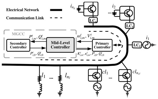
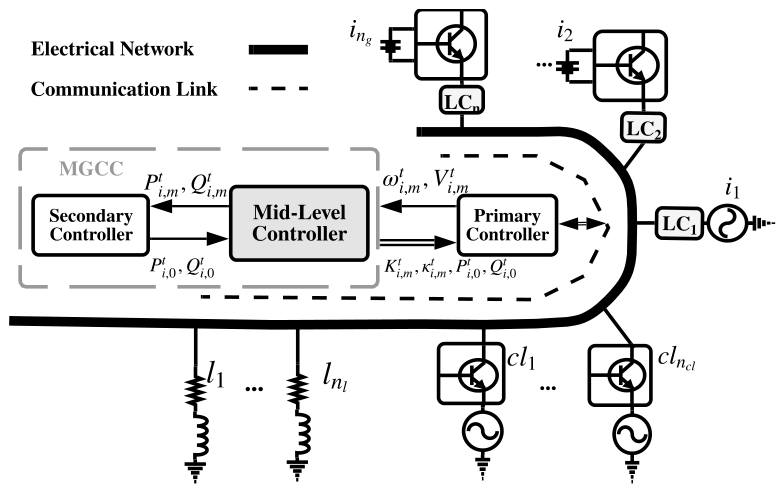
Consider an isolated microgrid within a distribution network, as illustrated in Figure 1, comprising distributed generation (DG) units (), energy storage systems (batteries) (), controllable loads (), and critical loads (), all connected through buses () in the electrical grid.
Figure 1.
A schematic illustration of the microgrid hierarchical control system.
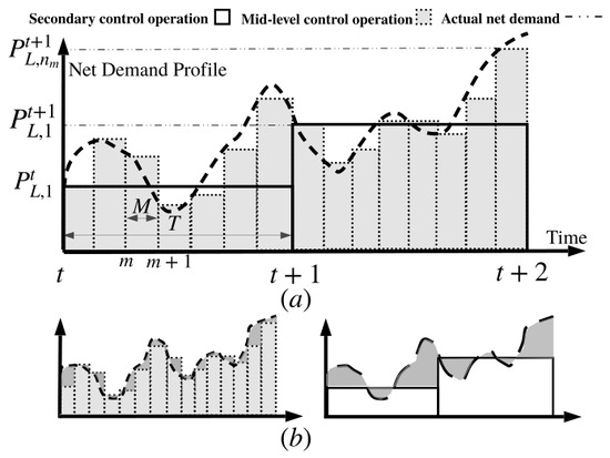
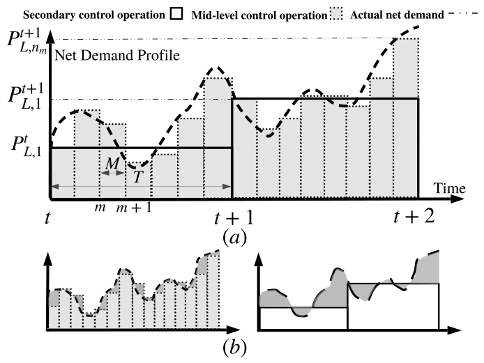
The microgrid consists of n local controllers (LCs) for DG units and dispatchable loads, which manage frequency and voltage at the primary control level. At the secondary control level, the microgrid central controller (MGCC) ensures stable and optimal operation. The mid-level controller addresses the challenges posed by the timescale differences between the fast-acting primary controller, which enforces synchronization, and the slower secondary controller by optimizing the droop controller parameters to bridge this gap. Figure 2 illustrates the stair-step pattern employed by the mid-level and secondary controllers, with dispatch time intervals M and T indexed by m and t, respectively. The mid-level control significantly reduces the unsupplied actual net demand , which is notably higher at the secondary control level, emphasizing the crucial role of mid-level control in ensuring efficient operation.
Figure 2.
(a) Stair-pattern provision of net demand profile. (b) Net demand coverage of mid-level and secondary controllers.
During each time interval T, the secondary controller adjusts the reference active/reactive power levels , with the goal of minimizing operational costs and reducing ESS lifecycle degradation. In a traditional UC model, these reference power levels modify the droop control curves at the primary control level, resulting in updated frequency and voltage droop settings. For a larger islanded microgrid with significant renewable energy penetration, frequent adjustments to the active/reactive reference power can lead to system frequency and voltage deviating beyond acceptable operational limits. The mid-level controller reduces these deviations by breaking the dispatch horizon T into sub-intervals, each with duration M, and optimizing droop control parameters to enhance microgrid performance. The primary controller then manages frequency and voltage by coordinating the rated and operating active/reactive power levels between neighboring controllable units during each dispatch sub-interval [23].
2.1. Droop Power Sharing Control
An imbalance between the variation in DG power () and the variation in net electrical power demand (), represented as the total power variation (), results in a shift in the nominal frequency (). Likewise, variations in the total reactive power cause output voltages to deviate from their desired values. To manage these deviations, DG units and controllable loads adjust their generation and consumption power using droop control, based on the power-balance principle of synchronous generators (SGs). To integrate the primary controller with the mid-level control model, a modified diffusive-averaging droop controller (DADC) is introduced [5]. Power sharing is achieved by adjusting the droop slope (), the diffusive averaging frequency coefficient (), and the control variable () for each active generator or controllable load within each dispatch interval/sub-interval, indexed by t and m. Local controllers (LCs) communicate to regulate frequency via diffusive averaging terms , where if generators/loads i and k are connected, and otherwise. The DADC problem is formulated as follows:
where is the frequency of the ith generator/load. A similar approach is used for voltage droop control, where generators share reactive power based on the voltage droop slope (), voltage gain (), maximum reactive power (), diffusive voltage coefficients (), communication matrix (), and control variable (). The DADC regulates the bus voltage to the nominal value using:
2.2. Components in Frequency and Voltage Control
The components of the islanded microgrid can be categorized into three main groups: inverter-based generators, SGs, and loads.
2.2.1. Inverter-Based Generators
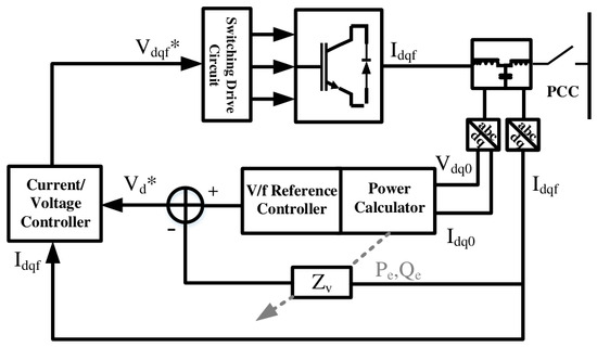
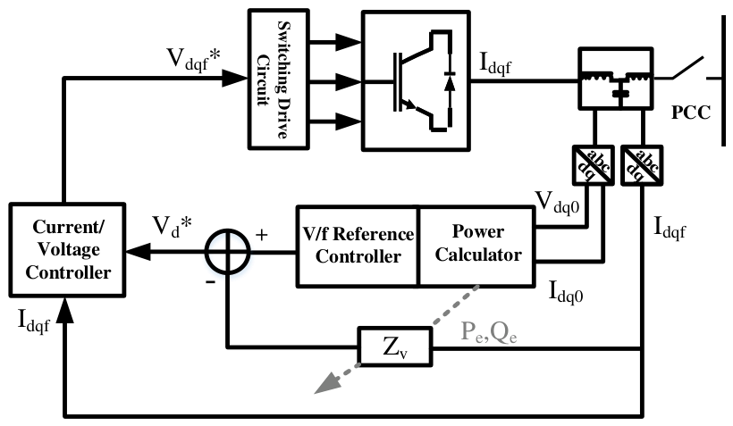
Voltage-source inverters, as part of back-to-back converters (e.g., ESS units), consist of three cascaded control loops: power, voltage, and current controllers. These controllers ensure adequate sharing of active and reactive power, as well as stable operating conditions [24]. A virtual impedance is introduced to the voltage control loop to compensate for output voltage deviations and stabilize the voltage control system. Changes in the operating point lead to changes in the virtual impedance value. The proposed adaptive virtual impedance () is tuned by the mid-level controller, based on a sensitivity analysis of operating active/reactive power (), as derived in [25]. Figure 3 illustrates the virtual impedance added to the voltage/current controller.
Figure 3.
Inverter controller design with virtual impedance consideration. The asterisk denotes the reference value used by the corresponding control loop.
2.2.2. Synchronous Generators
A typical synchronous generator (SG), such as a diesel generator, consists of several key components: the governor, turbine, exciter, and AC machine [26]. The frequency in an SG changes based on the difference between the mechanical driving power and the electrical power generated, as described by swing theory. Here, J represents the inertia coefficient in , indicating the power change per unit frequency change. The turbine and governor components, with gains () and time constants (), are used to compensate for power generation changes that occur due to frequency deviations in the microgrid [27]. Voltage is similarly regulated through a sensor (), exciter (), automatic voltage regulator (), and generator ().
2.2.3. Frequency–Voltage-Dependent Load
The loads in the microgrid are typically modeled using a voltage-dependent equation and can be represented by an equivalent ZIP load. The loads operate at their nominal voltage before any voltage change , with the power change , where is the active power of the load under nominal operating conditions in the sub-interval. In general, the voltage change is highly dependent on the load characteristics. The relationship between changes in voltage and frequency is given by . A detailed study on frequency–voltage-dependent loads demonstrates the validity of these equations [28].
3. Small-Perturbation Stability Analysis
The small-perturbation model is analyzed using eigenvalue analysis by linearizing the islanded microgrid. While this approach is only applicable around the operating point, it provides a necessary condition for microgrid stability [13]. To perform the eigenvalue analysis, a small-signal state-space model of the entire microgrid is developed at a specific operating point. The microgrid state-space model is divided into three sub-modules: generator, network, and load. Models for all lines and loads are derived from [29,30]. A comprehensive model of the islanded microgrid is constructed by integrating the state-space models of generators, the network, and loads using mapping matrices. These matrices link the output currents from generators or loads to specific nodes within the system.
4. Dynamic Voltage and Frequency Controller
As illustrated in Figure 2, the net demand profile does not abruptly transition from to at the tth dispatch interval but rather changes gradually from to over the time period T. This gradual change requires real-time adjustments to generation power based on actual measurements taken at time sub-intervals of M.
Dynamic programming is a powerful tool for addressing optimization problems, particularly in complex, nonlinear microgrid operations. However, the computational demands of performing feed-forward/backward numerical processes make it challenging to solve such optimization problems, especially in multi-objective microgrid control [16]. To overcome these challenges, adaptive critic control is developed to approximate the cost-to-go function, involving a model, action, and two critic neural networks. In this paper, the term adaptive critic control refers to an approximate dynamic programming structure in which the critic networks estimate the gradient of long-term utility functions and the action network updates the control policy using these estimates. The DVFC is therefore the control application, while adaptive critic control is the learning and optimization mechanism used to implement it.
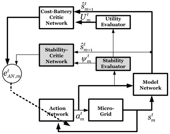
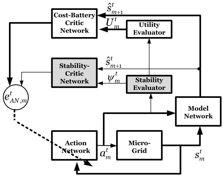
As depicted in Figure 4, an adaptive critic control architecture is proposed to maintain the microgrid stability margin () within an acceptable range while minimizing operating costs and ESS lifecycle degradation (). This approach relies on measurements of available microgrid states (), approximated system states (), and action control variables () at time t over duration T, indexed by m. The action vector comprises four sets of control variables: coefficients () of the diffusive averaging droop controller, virtual impedances (), and frequency–voltage controller (FVC) gains () for the generator [5]. The output states of the microgrid network include seven variables: the active/reactive power of generators and loads (), frequency/voltage deviations (), and the SOC of storage (), represented by:
Figure 4.
General layout for adaptive critic control with two networks.
Here, and are the active- and reactive-power diffusive averaging coefficients, is the adaptive virtual impedance of inverter-interfaced resources, and is the FVC gain of the synchronous generator. The state variables , , , and denote deviations from the scheduled active power, reactive power, nominal angular frequency, and nominal voltage, respectively. The subscript denotes controllable load variables, and denotes the SOC of ESS unit j. These definitions apply to the utility functions and constraints in the following equations unless a different local definition is explicitly stated.
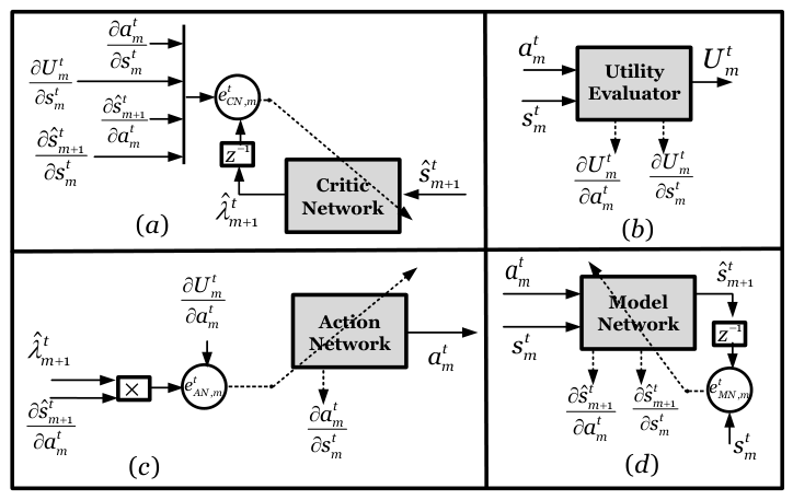
The mathematical representation of the adaptive critic model, encompassing action variables, microgrid actual and approximated states, and errors in the model (), action (), and critic () networks, is illustrated in Figure 5. The details of the adaptive critic model are discussed as follows.
Figure 5.
Detailed mathematical representation of DVFC: (a) critic network; (b) utility evaluator; (c) action network; and (d) model network.
4.1. Model Network Design
The islanded microgrid experiences perturbations such as load variations, resulting in different operating conditions for DG units across current and future dispatch intervals. The model network simulates the behavior of the microgrid in response to the current state and control actions, and predicts future system states to facilitate cost-efficient generation scheduling and efficient ESS utilization.
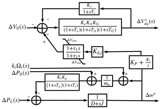
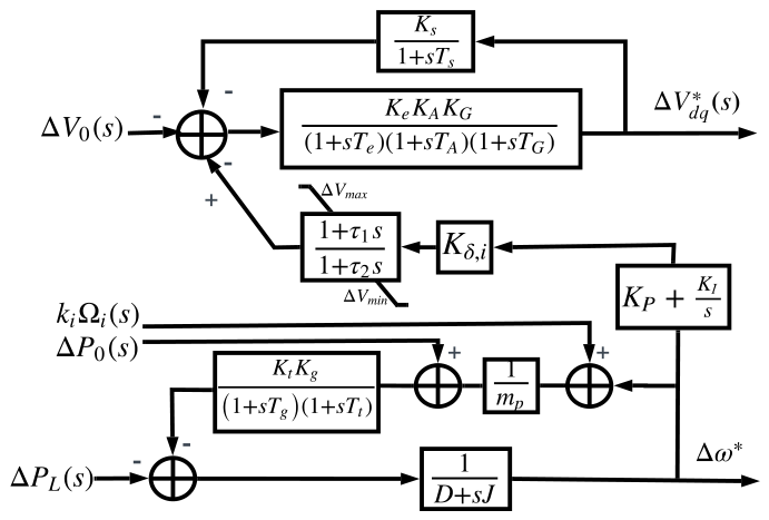
As shown in Figure 6, the error signal generated by the frequency control loop is processed through a PI controller with gains and to minimize the steady-state error. Following this, a lead-lag compensator with time constants and is applied to the input and output of the voltage control loops. This FVC introduces a gain, , to dampen oscillations generated by the frequency control loop and to establish the relationship between the system operating frequency and voltage. Similar to the inverter-based generator controller, the FVC is equipped with a low-pass filter/power calculator (LPF/PC) module to compute the average active and reactive power.
Figure 6.
The FVC model for the SG [24,28]. The asterisk denotes the reference input signal for the corresponding control block.
Accurate predictions are only possible if the difference between the one-step delayed output of the model network () and the actual microgrid output () is minimized. The model network prepares estimated states for the next step, , along with the derivatives of the estimated state at the sub-interval with respect to the action and actual state variables at the sub-interval, which are used for training the critic networks.
4.2. Feed-Forward Critic Network Process
The distributed generation units react to net demand changes based on the DADC mechanism; however, generation scheduling becomes suboptimal if the frequency and voltage controller parameters remain constant during each dispatch interval. The primary function of the critic model is to approximate objective functions, which depend on the current and estimated states and control actions. In the implemented ADHDP structure, the critic networks are feed-forward neural networks trained with backpropagation and temporal-difference error signals. Their role is to learn differentiable approximations of the nonlinear cost-to-go functions so that the action network can update the controller without repeatedly solving a mixed-integer optimization problem online. The optimal strategy of the critic network is to minimize a multi-objective utility function, which includes the operating costs of DGs, ESS lifecycle degradation, and microgrid frequency and voltage regulation. This is represented by the multi-objective operational cost-to-go function and the microgrid stability margin , subject to technical constraints. To ensure the stability of the microgrid within an acceptable margin, the stability critic network operates as an inner control loop of the operational critic network. The stability evaluator checks the Stability Index (SI) of the DVFC, which reflects the stability margin loss or improvement due to changes in effective parameters or loading conditions. Let and denote the stability margins for the base load (i.e., no change in load) and the loading condition at the sub-interval of the dispatch time, respectively. Following the small-signal formulation in [13], is obtained from the real part of the dominant eigenvalue of the linearized microgrid state matrix under the current state-action pair. Negative values indicate a stable operating point, whereas movement toward the imaginary axis indicates reduced damping. Thus, the SI is formulated as:
The operational critic network loop, which operates at a slower timescale compared to the stability control loop, aims to mitigate the effects of uncertainties on voltage and frequency control by minimizing ESS lifecycle degradation and operational costs. The output power of DGs influences the voltage at the bus and the frequency of the microgrid. The corresponding utility functions for voltage and frequency are expressed as follows:
These utility functions represent the relationship between the control objectives and the operating conditions, guiding the operational critic network to optimize microgrid performance while ensuring system stability.
The operational cost of the dispatchable generation unit i changes in response to at the operating generation power and is represented by the quadratic cost utility function () as follows:
where () and () are economic coefficients for the fuel-based generator, and / and / denote start-up and shut-down costs and the corresponding binary variables. In conventional UC, fast-response generators (e.g., batteries) must respond to frequency changes in a short time interval, which degrades the ESS lifecycle. However, the ESS lifecycle utility function, , keeps the discharge depth between the minimum and maximum levels for the SOC of the ESS () by controlling as follows:
where the first exponential term penalizes deep discharges close to the minimum SOC, while the second term penalizes overcharging near the maximum SOC. By explicitly modeling SOC-dependent degradation, the controller discourages operation at extreme charge levels and limits high depth-of-discharge cycles, both of which are key drivers of Li-ion battery wear [31,32]. Simulation studies demonstrate that this formulation can extend the battery lifecycle by nearly twofold, reducing the effective degradation rate compared to non-optimal DVFC policies. A weighted-sum method is used to determine a balanced energy dispatch among the solutions obtained from the utility functions. Before aggregation, each utility term is normalized using the minimum and maximum values observed in the offline training scenarios so that no term dominates only because of its physical unit. The non-negative scaling weights satisfy for , where a higher scaling weight indicates higher priority. In Scenario 5, the final set of normalized weights is selected by comparing Pareto-ranked solutions using a fuzzy membership score, so the reported solution is not obtained by an arbitrary single-objective preference. The overall utility function is:
The optimal control problem is to generate the power dispatch of DGs in the sub-interval by minimizing the cost-to-go operational function in Bellman’s equation of dynamic programming in a step-by-step way [16]. It also keeps the stability margin of the microgrid within the desired range by maximizing the cost-to-go stability function . These functions are given by:
where is the learning factor in dynamic programming. The technical constraints include the following:
(1) Power Balance: Unlike conventional UC, the generation power must match demand at each dispatch time, based on Equations (1)–(4).
(2) Fossil-Fuel Units: Constraints are associated with DG active/reactive power, start-up and shut-down binary variables, and ramp-up/ramp-down power limits for fossil fuel generation units. It is assumed that the ramp-up power equals the ramp-down power ():
where is a binary variable that determines the on/off status of the DG.
(3) ESS Charge/Discharge: The ESS operates in three different modes, i.e., charging (), discharging (), and idle status (). The following set of constraints models SOC behaviors:
where and represent the efficiency of charging and discharging, and is the ESS capacity.
The DVFC critic network is trained online to approximate the derivatives of the estimated cost-to-go with respect to the estimated state variable from the model network, denoted by , and to minimize the critic network error . Here, is given by
The same convention is applied for the stability critic network.
4.3. Action Network Design
The action network determines the optimal values for the action variables (i.e., ) by minimizing the cost-to-go function in the critic network. This network is trained online to approximate the optimal control law by minimizing the action network error (i.e., ), given by
where the partial derivatives are obtained from the model network, critic network, and utility evaluator as shown in Figure 5 [16]. Note that the computational time of the critic network training is much higher than that for the action and model networks, but has less power to change the action variables from their desired values.
4.4. Design and Initialization of DVFC
The pre-training of the three networks accelerates the convergence of the learning process. The model network, which approximates microgrid dynamics over a wide operating range, is initially trained using the error of state variables. Table 2 provides the typical convergence time for each neural network, evaluated using an Intel(R) Core(TM) i7-8650 1.90 GHz (4 processors).
Table 2.
Typical convergence time for neural networks.
Note that the computational time required for simulation depends significantly on the hardware capabilities. The pre-training of the critic network is performed using results obtained from a mixed-integer nonlinear programming (MINLP) method in GAMS, solved using the CPLEX solver for different load and renewable energy perturbations. This pre-training must be done for each test case based on the configuration of the cost-to-go function.
The online adaptation is carried out sequentially for the model, action, and critic networks. During the training of one network, the other networks remain fixed (no weight updates). The feed-forward and backward training of action and critic networks continues until the errors converge within a range of .
5. Numerical Results
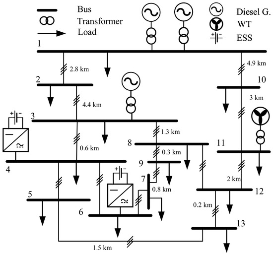
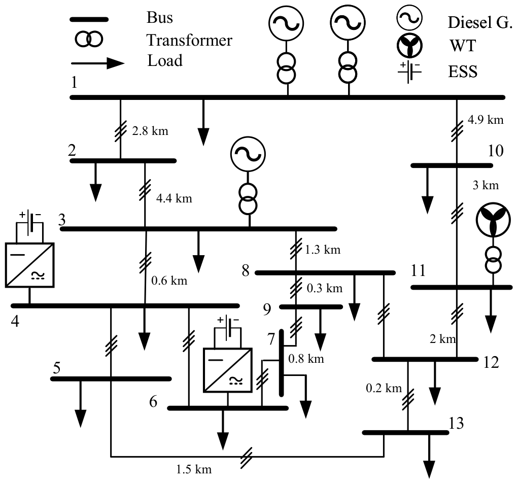
To evaluate the performance of the proposed mid-level controller in an islanded microgrid, a modified CIGRE medium-voltage benchmark network was modeled and simulated exclusively in MATLAB/Simulink. CIGRE (Conseil International des Grands Réseaux Électriques) benchmark systems provide standardized distribution-network models for evaluating renewable and distributed energy resource integration; the medium-voltage benchmark is widely used because it includes representative feeder impedances, distributed resources, and load buses for reproducible controller validation [4,33]. MATLAB/Simulink was selected because it provides a comprehensive environment for system-level modeling, control design, and time-domain simulation, offering robust numerical solvers and block libraries well-suited for microgrid dynamics and controller validation. The schematic of the test system is presented in Figure 7 [4]. The benchmark represents a European medium-voltage network with a total installed capacity of 5 MVA, comprising two diesel-based synchronous generators (SGs) connected to buses #1 and #3, a wind turbine (WT) at bus #11, and an energy storage system (ESS) at bus #6. The network includes 13 critical loads, while the feeders are represented by 14 coupled -sections. Further details on the system configuration and parameters are provided in [4,33].
Figure 7.
Microgrid test case based on the modified CIGRE benchmark [4].
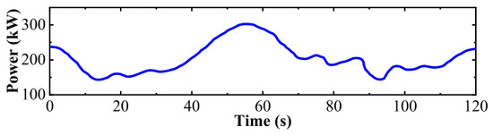
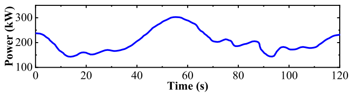
The ESSs at buses #6 and #4 are represented as Li-ion batteries connected through bidirectional voltage source controllers. Each ESS has a maximum power rating of 300 kW and an energy rating of 6000 kWh. The initial SOC is set to 94%, and the minimum acceptable SOC is 600 kWh (10%). The 94% upper operating point is used instead of 100% to avoid operation near the high-voltage region where lithium plating and accelerated calendar degradation may occur, while the 10% lower bound prevents over-discharge and preserves usable energy for frequency support [31,32]. The droop regulation capacity is 30 MW/Hz. It specifies the amount of active power adjustment the ESS can provide in response to frequency deviations, i.e., 30 MW of regulating power for every 1 Hz deviation. This parameter characterizes the responsiveness of the ESS as a high-frequency droop controller, enabling much faster frequency support compared to conventional synchronous generators. It is distinct from the maximum ramp rate (kW/s), which defines the physical limit on how quickly the power output can change over time. The WT at bus #11 has a nominal rating of 800 kVA. The nominal ratings, operating cost coefficients, start-up and shut-down costs, and ramp rates are provided in [4]. The diesel-based SGs connected to buses #1 and #3 are responsible for voltage regulation using the proposed FVC. These diesel-based SGs act as the master controllers for reactive power sharing, while the batteries and wind turbine (WT) serve as slave units supplying or consuming reactive power. Table 3 summarizes the cost coefficients, generation limits, and operational constraints of diesel-based synchronous generators, which are essential for unit commitment and dispatch studies. Table 4 presents the electrical parameters and droop coefficients of distributed generators in the CIGRE test case, defining their voltage and frequency control characteristics. The nominal droop coefficients are selected from the CIGRE-based microgrid parameterization and then checked through the eigenvalue sensitivity study discussed below.In particular, determines the active-power/frequency sharing slope, determines the reactive-power/voltage sharing slope, and their hatted counterparts define the adjusted slopes used by the diffusive averaging controller. Increasing these coefficients improves sharing speed but can reduce damping; therefore, the selected values are those that satisfy proportional sharing while keeping the dominant eigenvalues in the stable region. Table 5 lists the Li-ion battery energy storage system parameters used in the simulation studies. Together, these tables provide the fundamental data required to model system costs, dynamics, and stability performance. The WT generation over a 120-s period is depicted in Figure 8 [4]. Various initial values for the FVC were tested, with the best performance obtained using time constants of s and s. The effectiveness of the DVFC during wind fluctuations is evaluated by comparing the microgrid response with and without its presence. The wind power fluctuates between 15% and 35% of the 800 kVA rating, as shown in Figure 8. The initial values for utility weights are set to 0.25 for , where . The neural networks were initialized using Xavier initialization for weights with small random biases, and pre-training was performed on 15,000 scenarios encompassing both nominal and disturbed operating conditions. Training was carried out using gradient descent with a fixed learning rate of and a mini-batch size of 64. Convergence was determined by monitoring the squared error of the critic and action networks, with termination occurring when the error reached within or after a maximum of iterations. To ensure robustness, multiple runs with different random seeds were conducted, which consistently demonstrated stable convergence. The model and critic networks were trained offline, while the Action network was continuously adapted online to maintain computational efficiency and enable real-time applicability of the controller.
Table 3.
Rated power and cost parameters for diesel-based SGs.
Table 4.
System parameters and DG characteristics in the CIGRE test case.
Table 5.
Parameters of the Li-ion battery energy storage system (ESS).
Figure 8.
The measured wind turbine generation at bus #11 [4].
5.1. Dominant Eigenvalue Traces Versus System Parameters
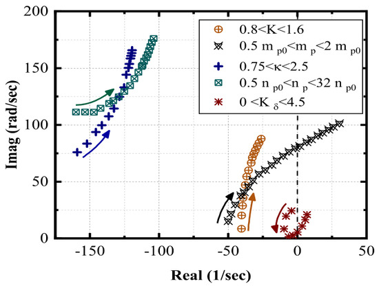
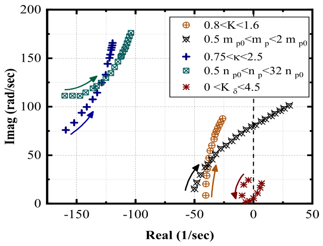
We investigate the impact of DVFC inputs on the microgrid’s small-perturbation stability by monitoring the dominant eigenvalues. Controller gains are varied independently around their nominal values within specific intervals, and the resulting eigenvalue trajectories are shown in Figure 9 with respect to changes in K, , , , and . The eigenvalues for power sharing mode and FVC gains correspond to the low-frequency critical mode of the microgrid, and are particularly sensitive to variations in these parameters. Consequently, eigenvalues along the real axis are closely associated with the frequency dynamics of the ESS and the FVC behavior of the SG, whereas the complex conjugate eigenvalues represent the voltage dynamics of inverter-interfaced ESS. In the DVFC scheme, the stability index (SI) varies from for to for , demonstrating improved robustness and stability compared to the changes in the frequency droop controller while maintaining the same power-sharing behavior.
Figure 9.
Eigenvalue traces of the microgrid control system for different values of the ADHDP controller and FVC gains. Gains increase in the direction of the arrows.
Figure 9 shows that increasing initially improves the microgrid damping metric until a point where further increments lead to deterioration in overall microgrid damping. It is observed that results in the best stability margin and microgrid damping; hence, this value is selected as the FVC gain for time-domain simulation studies. We also assess the time delay margin for each controller to ensure microgrid stability. The time delay margins for the mid-level controller and the secondary controller are 13.2 s and 55 s, respectively, under stable microgrid operation.
5.2. DVFC for Frequency and Voltage Regulation (Scenarios 1 and 2)
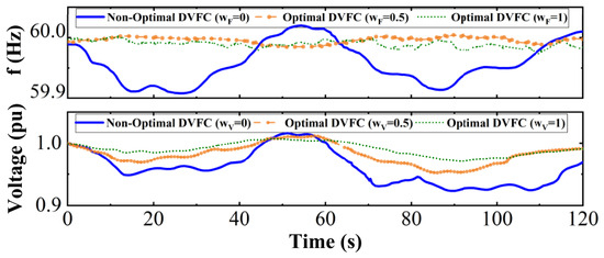
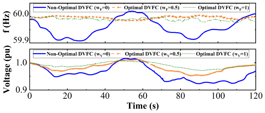
In Scenario 1, the weight associated with frequency regulation is tested over a range from 0 to 1 to evaluate the effectiveness of the cost-to-go function for frequency response. Figure 10 shows the frequency response under different weights, indicating that yields a smaller frequency deviation from the nominal value compared to the non-optimal DVFC (). In Scenario 2, with , the voltage regulation is analyzed to minimize the bus voltage deviation from its nominal value. Figure 10 illustrates that the voltage deviation is maintained within the acceptable operating range of [] pu ( V), compared to a non-optimal solution where the voltage profile drops below pu under wind fluctuations. Overall, the DVFC is capable of providing smooth frequency and voltage regulation as wind power increases up to 35%.
Figure 10.
Frequency regulation in Scenario 1 and voltage response to wind power fluctuation in Scenario 2.
5.3. DVFC Versus ESS Penetration (Scenario 3)
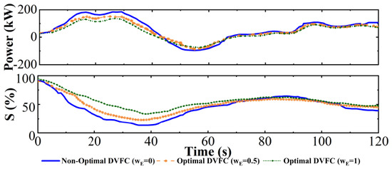
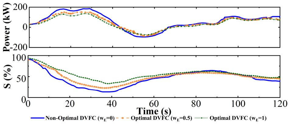
An ESS is connected to bus #6 and is charged or discharged based on the power supply imbalance in the microgrid. The ESS has a regulation capacity of 30 MW/Hz [28], which allows for higher frequency response compared to the diesel-based SGs. To achieve a longer ESS lifetime and improve active/reactive power sharing control, we utilize a droop control model based on Equation (2). Initially, the ESSs are fully charged (approximately 94%), and the minimum state of charge (SOC) is set at 10%. The required ESS capacity over the 120-s interval is assumed to be 20 kWh, with wind power fluctuations as shown in Figure 8, repeating periodically 30 times in an hour. Thus, the ESS should be large enough to store 600 kWh. As shown in Figure 11, the DVFC approach results in a reduction of discharged power compared to the non-optimal one, maintaining the ESS’s SOC within a desired range, which improves the ESS lifecycle over the long term. It is assumed that the charging and discharging modes of the ESS follow the pattern shown in Figure 11 more than 30 times per hour. Since Li-ion cycle life is strongly dependent on the depth of discharge, the cycle estimates are derived from the SOC-dependent degradation utility in Equation (12) and calibrated against published cycle-life trends for Li-ion batteries [31,32]. Consequently, the ESS lifecycle is estimated at 2000 cycles for non-optimal DVFC (), 3500 cycles for optimal DVFC with , and 4200 cycles for optimal DVFC with .
Figure 11.
Active power and SOC of ESS during wind fluctuations in Scenario 3.
5.4. Minimum Operating Cost by DVFC (Scenario 4)
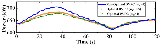
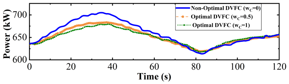
Scenario 4 is conducted to evaluate the performance of the DVFC in achieving a more efficient dispatch solution in the CIGRE test case. In this scenario, only diesel-based SGs are considered as dispatchable generators, while the wind turbine (WT) serves as the non-dispatchable generator with wind power penetrations of 30% and 35%. Similar to scenarios 1–3, the DVFC’s performance is compared with that of the non-optimal solution () over a 120-s duration. Figure 12 shows the power generation from the diesel unit at bus #3. A higher weight for the cost utility function results in lower power generation from the diesel generators, which act as cost-driven units.
Figure 12.
Dispatch of diesel-based SG at bus #3 in Scenario 4.
To validate the effects of the operating cost and energy generated by the diesel-based SGs, the system is simulated for 24 h with dispatch intervals of 55 s (i.e., s). Table 6 shows that the operating cost of the DVFC is lower than that of conventional UC, indicating that the conventional UC overestimates the required energy from expensive diesel-based SGs during each sub-interval. The DVFC reduces the operating cost by 3.83%, resulting in savings of $2016 per day compared to conventional UC.
Table 6.
Energy of diesel-based SGs (kWh) and operating cost in Scenario 4.
5.5. Optimum Performance of DVFC (Scenario 5)
The best overall performance of the DVFC across all utility functions is obtained to demonstrate how the DVFC results in the optimal dispatch solution. We define performance indices (PIs) for frequency and voltage, given by
To validate the advantage of the proposed DVFC compared to the conventional UC, three deterministic load and wind turbine (WT) profiles are considered. The conventional UC is evaluated using a MINLP approach with the CPLEX solver over a 24-h operation period. The multi-objective function is solved using a fuzzy weighted sum algorithm. Optimal solutions for each normalized utility function are obtained separately and then ranked based on a fuzzy Pareto front selection. The optimal weights for all normalized utility functions are , , , and (with ). Table 7 summarizes the differences between the DVFC and the conventional UC based on four different indices. The conventional UC optimizes different objective functions in each iteration, focusing on two main objectives: a cost-driven function (CDF) and an ESS-driven function (EDF).
Table 7.
Optimal DVFC vs the conventional UC for 24 h of operation in Scenario 5.
To further clarify the tradeoffs in Table 7, Table 8 reports the relative reduction achieved by the DVFC with respect to each UC benchmark. Positive values indicate that the DVFC reduces the corresponding index compared with the reference method, while negative values indicate a tradeoff in which the DVFC has a higher value for that specific index. The results show that the DVFC provides the largest improvements in frequency and voltage regulation while keeping cost and ESS-degradation tradeoffs within a narrow range.
Table 8.
Relative reduction of DVFC indices with respect to the UC benchmarks in Scenario 5.
To evaluate the DVFC’s performance over a 24-h period, four different models—cost-driven function (CDF), ESS-driven function (EDF), a combined CDF and EDF without frequency and voltage regulation, and the proposed DVFC—are compared in Table 7. The proposed DVFC shows improvements of 40–50% and 60–65% in frequency and voltage performance indices (PIs) compared to conventional UCs, respectively. The minimum ESS lifecycle degradation, denoted as , is achieved by the individual EDF model, while the minimum operating cost (50,688) is achieved by the individual CDF model.
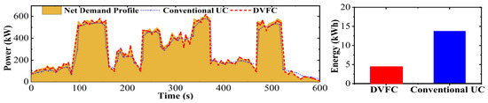
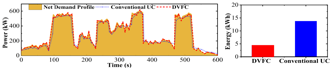
Although the DVFC demonstrates higher operating cost and ESS lifecycle degradation compared to the individual CDF and EDF models, it strikes a balance between optimizing operating cost and minimizing ESS lifecycle degradation while maintaining minimal deviations in frequency and voltage from their desired values. Furthermore, the DVFC exhibits superior performance in covering the net demand profile compared to the conventional UC, as shown in Figure 13. The DVFC reduces the uncovered net demand profile to less than 30% of that observed with the conventional UC, reducing the uncovered energy from 14.85 kWh to 4.7 kWh.
Figure 13.
Coverage of the net demand profile and total uncovered net demand profile for both conventional UC and the proposed DVFC.
5.6. Plug-and-Play Functionality of DVFC (Scenario 6)
The plug-and-play functionality is tested by disconnecting diesel-based SG #1 at s and reconnecting it at s during each minute. This test is repeated for a one-hour simulation (i.e., 60 events) to validate the effectiveness of the DVFC. During the downtime, a synchronization action is performed to synchronize SG #1 with the remaining islanded microgrid before reconnection. Control parameters are the same as in Scenario 1. Two frequency and voltage indices are defined to evaluate the DVFC’s performance during this process. Table 9 presents the average frequency deviation in three cases–UC without ESS, UC with ESS, and DVFC–over the one-hour operation. The DVFC significantly reduces the frequency deviation, , during the plug-and-play functionality.
Table 9.
Comparison of Parameters for UC Without ESS, UC With ESS, and DVFC.
Additionally, the impact of this process on the voltage deviation at bus #1, denoted as , is found to be negligible for the DVFC approach compared to the UC model. The ESS utilization is also reported in Table 9, indicating that with the DVFC controller, ESS utilization decreases by 30%, resulting in an active energy saving of approximately 1.32 kWh for each plug-and-play event. Without loss of generality, the DVFC controller ensures accurate power sharing, as well as frequency and voltage regulation, despite the connection and disconnection of SG #1.
6. Conclusions and Future Work
This paper presents a DVFC for an islanded microgrid, aimed at optimizing the operating cost of dispatchable units and extending the ESS lifecycle while maintaining frequency and voltage within a desired range. The DVFC serves as a mid-level controller, bridging the time intervals between the primary and secondary controllers and avoiding the stair-patterned generation scheduling observed in conventional UCs. The DVFC leverages dynamic programming to approximate microgrid operating cost, battery lifecycle, and frequency/voltage regulation requirements for upcoming time steps, thereby determining optimal dispatches for DG units. The DVFC does not require a detailed mathematical model of the microgrid to calculate utility functions such as voltage and frequency regulation. Through several scenarios tested in a modified CIGRE microgrid, it has been demonstrated that the DVFC significantly reduces frequency and voltage deviations from their desired values and minimizes the operating costs of DGs. The optimal control policy of the DVFC extends the battery lifecycle by up to twofold. With appropriate training and parameter configuration, the DVFC can make islanded microgrids self-adaptive, stable, and efficient in terms of cost and ESS utilization. Although the proposed DVFC concept has demonstrated effectiveness under balanced test systems and simplified assumptions, several gaps remain. Current formulations do not address unbalanced operating conditions, unequal or random communication delays, synchronous generator control delays, or plug-and-play events involving multiple SG and ESS units at the same time. The dispatchable-resource set is also limited to diesel-based synchronous generators, although the same framework can be extended to gas turbines and other synchronous-machine resources with comparable electromechanical dynamics. Future work may therefore focus on extending the DVFC to enhance resilience against simultaneous generation, ESS, and load disconnection or reconnection events; incorporating dynamic state prediction models such as wind power generation to improve adaptability under renewable variability; comparing the plug-and-play response with advanced DRL, MPC, and event-triggered secondary controllers; and developing more rigorous multi-objective optimization and robust delay-handling strategies to strengthen the controller’s applicability in practical microgrid environments.
Author Contributions
Conceptualization, M.P.; methodology, M.P. and W.Z.; software, M.P.; validation, W.Z. and F.F.; formal analysis, M.P.; investigation, M.P.; resources, F.F.; writing—original draft preparation, M.P.; writing—review and editing, M.P., W.Z. and F.F.; visualization, M.P.; supervision, W.Z. All authors have read and agreed to the published version of the manuscript.
Funding
This work was supported by a research grant from the Natural Sciences and Engineering Research Council (NSERC) of Canada.
Data Availability Statement
The original contributions presented in this study are included in the article. Further inquiries can be directed to the corresponding author.
Conflicts of Interest
Author Mehdi Parvizimosaed was employed by the company Edgecom Energy Inc., author Farid Farmani was employed by the company New York Power Authority. The remaining authors declare that the research was conducted in the absence of any commercial or financial relationships that could be construed as a potential conflict of interest.
Abbreviations
The following abbreviations are used in this manuscript:
| UC | Unit Commitment |
| DG | Distributed Generation |
| DVFC | Dynamic Voltage and Frequency Controller |
| ESS | Energy Storage System |
| SG | Synchronous Generator |
| WT | Wind Turbine |
| FVC | Frequency and Voltage Controller |
| SI | Stability Index |
| EDF | ESS-Driven Function |
| CDF | Cost-Driven Function |
| CIGRE | Conseil International des Grands Réseaux Électriques |
References
- Ghasemi, N.; Ghanbari, M.; Ebrahimi, R. Intelligent and optimal energy management strategy to control the micro-grid voltage and frequency by considering the load dynamics and transient stability. Int. J. Electr. Power Energy Syst. 2023, 145, 108618. [Google Scholar] [CrossRef] [Scilit]
- Sepehrzad, R.; Hedayatnia, A.; Amohadi, M.; Ghafourian, J.; Al-Durra, A.; Anvari-Moghaddam, A. Two-stage experimental intelligent dynamic energy management of microgrid in smart cities based on demand response programs and energy storage system participation. Int. J. Electr. Power Energy Syst. 2024, 155, 109613. [Google Scholar] [CrossRef] [Scilit]
- Abdelaziz, M.M.A.; Shaaban, M.F.; Farag, H.E.; El-Saadany, E.F. A multistage centralized control scheme for islanded microgrids with PEVs. IEEE Trans. Sustain. Energy 2014, 5, 927–937. [Google Scholar] [CrossRef] [Scilit]
- Farrokhabadi, M.; Canizares, C.A.; Bhattacharya, K. Unit commitment for isolated microgrids considering frequency control. IEEE Trans. Smart Grid 2018, 9, 3270–3280. [Google Scholar] [CrossRef] [Scilit]
- Simpson-Porco, J.W.; Shafiee, Q.; Dörfler, F.; Vasquez, J.; Guerrero, J.; Bullo, F. Secondary frequency and voltage control of islanded microgrids via distributed averaging. IEEE Trans. Ind. Electron. 2015, 62, 7025–7038. [Google Scholar] [CrossRef] [Scilit]
- Ahmad, S.; Shafiullah, M.; Ahmed, C.B.; Alowaifeer, M. A review of microgrid energy management and control strategies. IEEE Access 2023, 11, 21729–21757. [Google Scholar] [CrossRef] [Scilit]
- Liu, G.; Starke, M.; Xiao, B.; Tomsovic, K. Robust optimisation-based microgrid scheduling with islanding constraints. IET Gener. Transm. Distrib. 2017, 11, 1820–1828. [Google Scholar] [CrossRef] [Scilit]
- Morales-Espana, G.; Ramos, A.; Garcia-Gonzalez, K. An MIP formulation for joint market-clearing of energy and reserves based on ramp scheduling. IEEE Trans. Power Syst. 2014, 29, 476–488. [Google Scholar] [CrossRef] [Scilit]
- Zhao, Z.; Xu, J.; Guo, J.; Ni, Q.; Chen, B.; Lai, L.L. Robust energy management for multi-microgrids based on distributed dynamic tube model predictive control. IEEE Trans. Smart Grid 2023, 15, 203–217. [Google Scholar] [CrossRef] [Scilit]
- Rios, M.A.; Pérez-Londoño, S.; Garcés, A. Dynamic performance evaluation of the secondary control in islanded microgrids considering frequency-dependent load models. Energies 2022, 15, 3976. [Google Scholar] [CrossRef] [Scilit]
- Liu, T.; Chen, A.; Gao, F.; Liu, X.; Li, X.; Hu, S. Double-loop control strategy with cascaded model predictive control to improve frequency regulation for islanded microgrids. IEEE Trans. Smart Grid 2021, 13, 3954–3967. [Google Scholar] [CrossRef] [Scilit]
- Rios, M.A.; Garces, A. An optimization model based on the frequency dependent power flow for the secondary control in islanded microgrids. Comput. Electr. Eng. 2022, 97, 107617. [Google Scholar] [CrossRef] [Scilit]
- Parvizimosaed, M.; Zhuang, W. Enhanced active and reactive power sharing in islanded microgrids. IEEE Syst. J. 2020, 14, 5037–5048. [Google Scholar] [CrossRef] [Scilit]
- Han, F.; Lao, X.; Li, J.; Wang, M.; Dong, H. Dynamic event-triggered protocol-based distributed secondary control for islanded microgrids. Int. J. Electr. Power Energy Syst. 2022, 137, 107723. [Google Scholar] [CrossRef] [Scilit]
- Rosini, A.; Mestriner, D.; Labella, A.; Bonfiglio, A.; Procopio, R. A decentralized approach for frequency and voltage regulation in islanded PV-storage microgrids. Electr. Power Syst. Res. 2021, 193, 106974. [Google Scholar] [CrossRef] [Scilit]
- Venayagamoorthy, G.K.; Sharma, R.; Gautam, P.; Ahmadi, A. Dynamic energy management system for a smart microgrid. IEEE Trans. Neural Netw. Learn. Syst. 2016, 27, 1643–1656. [Google Scholar] [CrossRef] [Scilit]
- Meng, L.; Sanseverino, E.; Luna, A.; Dragicevic, T.; Vasquez, J.; Guerrero, J. Microgrid supervisory controllers and energy management systems: A literature review. Renew. Sustain. Energy Rev. 2016, 60, 1263–1273. [Google Scholar] [CrossRef] [Scilit]
- Mahdian Dehkordi, N.; Nekoukar, V. Adaptive distributed stochastic deep reinforcement learning control for voltage and frequency restoration in islanded AC microgrids with communication noise and delay. Sci. Rep. 2025, 15, 27315. [Google Scholar] [CrossRef] [Scilit]
- Li, S.; Blaabjerg, F.; Anvari-Moghaddam, A. A transferable DRL-based intelligent secondary frequency control for islanded microgrids. Electronics 2025, 14, 2826. [Google Scholar] [CrossRef] [Scilit]
- Huang, X.; Zeng, J.; Wang, T.; Zeng, S. An off-policy maximum entropy deep reinforcement learning method for data-driven secondary frequency control of island microgrid. Appl. Soft Comput. 2025, 170, 112694. [Google Scholar] [CrossRef] [Scilit]
- Liu, X.; Tang, J.; Zhou, Q.; Peng, J.; Huang, N. Coordinated optimization scheduling method for frequency and voltage in islanded microgrids considering active support of energy storage. Processes 2025, 13, 2146. [Google Scholar] [CrossRef] [Scilit]
- Duan, Q.-S.; Tang, Z.; Ding, D. Distributed adaptive optimal secondary control for AC islanded microgrid under multiple event-triggered mechanisms. ISA Trans. 2025, 163, 65–75. [Google Scholar] [CrossRef] [Scilit]
- Olivares, D.E.; Mehrizi-Sani, A.; Etemadi, A.H.; Cañizares, C.A.; Iravani, R.; Kazerani, M.; Hajimiragha, A.H.; Gomis-Bellmunt, O.; Saeedifard, M.; Palma-Behnke, R.; et al. Trends in microgrid control. IEEE Trans. Smart Grid 2014, 5, 1905–1919. [Google Scholar] [CrossRef] [Scilit]
- Abdelaziz, M.A.; Farag, H.E.; El-Saadany, E. Optimum reconfiguration of droop-controlled islanded microgrids. IEEE Trans. Power Syst. 2016, 31, 2144–2153. [Google Scholar] [CrossRef] [Scilit]
- Mahmood, H.; Michaelson, D.; Jiang, J. Accurate reactive power Sharing in an islanded microgrid using adaptive virtual impedances. IEEE Trans. Power Electron. 2015, 30, 1605–1617. [Google Scholar] [CrossRef] [Scilit]
- Savaghebi, M.; Jalilian, A.; Vasquez, J.C.; Guerrero, J.M. Autonomous voltage unbalance compensation in an islanded droop-controlled microgrid. IEEE Trans. Ind. Electron. 2013, 60, 1390–1402. [Google Scholar] [CrossRef] [Scilit]
- Zheng, D.D.; Madani, S.S.; Karimi, A. Closed-loop data-driven modeling and distributed control for islanded microgrids with input constraints. Control Eng. Pract. 2022, 126, 105251. [Google Scholar] [CrossRef] [Scilit]
- Farrokhabadi, M.; Canizares, C.A.; Bhattacharya, K. Frequency control in isolated/islanded microgrids through voltage regulation. IEEE Trans. Smart Grid 2017, 8, 1185–1194. [Google Scholar] [CrossRef] [Scilit]
- Liang, H.; Choi, B.J.; Zhuang, W.; Shen, X. Stability enhancement of decentralized inverter control through wireless communications in microgrids. IEEE Trans. Smart Grid 2013, 4, 321–331. [Google Scholar] [CrossRef] [Scilit]
- Pogaku, N.; Prodanovic, M.; Green, T.C. Modeling, analysis and testing of autonomous operation of an inverter-based microgrid. IEEE Trans. Power Electron. 2007, 22, 613–625. [Google Scholar] [CrossRef] [Scilit]
- Xu, B.; Oudalov, A.; Ulbig, A.; Andersson, G.; Kirschen, D.S. Modeling of lithium-ion battery degradation for cell life assessment. IEEE Trans. Smart Grid 2018, 9, 1131–1140. [Google Scholar] [CrossRef] [Scilit]
- Deshpande, R.D.; Uddin, K. Physics inspired model for estimating “cycles to failure” as a function of depth of discharge for lithium ion batteries. J. Energy Storage 2021, 33, 101932. [Google Scholar] [CrossRef] [Scilit]
- CIGRE Task Force C6.04.02. Benchmark Systems for Network Integration of Renewable and Distributed Energy Resources; Technical Brochure 575; CIGRE: Paris, France, 2014. [Google Scholar]


Disclaimer/Publisher’s Note: The statements, opinions and data contained in all publications are solely those of the individual author(s) and contributor(s) and not of MDPI and/or the editor(s). MDPI and/or the editor(s) disclaim responsibility for any injury to people or property resulting from any ideas, methods, instructions or products referred to in the content. |
© 2026 by the authors. Licensee MDPI, Basel, Switzerland. This article is an open access article distributed under the terms and conditions of the Creative Commons Attribution (CC BY) license.