


Abstract
Synchronous machines used in wind turbines typically use rare earth permanent magnets (PMs) due to the possibility of high power densities and efficiencies. However, alternative non-PM topologies are gaining popularity due to the cost and supply volatility of PMs. Wound-field flux-switching machines (WFFSMs), although boasting high torque densities and being PM-free, have lower power densities than PM machines. However, a double-stator wound-field flux-switching machine (DSWFFSM) exemplifies even greater power density. This study investigates the application of DSWFFSMs for direct-drive wind applications. Furthermore, the performance of an optimized 3 MW DSWFFSM design is compared with a single-stator WFFSM design. Both designs are based on the volume of a single-stator PM flux-switching machine from the literature. Although the torque per weight for the DSWFFSM and the single-stator WFFSM are similar, the torque per volume for the DSWFFSM is shown to be significantly exceptional. The torque ripple in the DSWFFSM is also smaller, but the efficiency is slightly lower than the single-stator WFFSM. The DSWFFSM design, which is shown to be comparable to PM-based topologies in terms of power density, highlights a low-cost, sustainable, clean energy generator topology.
1. Introduction
Renewable energy utilization has significantly increased recently as a result of industrial and population expansions, rising electrical energy demand, and the alignment of sustainable development goals [1]. Wind energy is among the widely used renewable energy sources due to its ease of harnessing and relatively low cost of energy [2].
Wind generators, which convert wind energy to electrical energy, are among the key components of the wind turbine. Important considerations when choosing an ideal wind generator include the torque density, cost, efficiency and reliability among others. Based on speed, wind generator drivetrains can be classified as either geared, semi-direct or direct drives [3]. Gearboxes are not required in direct-drive systems, and this can enhance wind turbine reliability and even system efficiency [4]. Consequently, some wind turbine manufacturers are now shifting to direct-drive systems [5].
Generally, PM synchronous machines (PMSMs) have high torque density, reliability and efficiency. However, PMs prices are unstable and costly [6]. Also, there are risks of PM demagnetization at high temperatures or currents [7]. As a result, interest in non-PM generator topologies is increasing. Although electrically excited synchronous machines (EESMs) are natural candidates for non-PM alternatives, traditional EESMs require slip ring and brush setups, which lead to reduced reliability. Consequently, topologies like wound-field flux-switching machines (WFFSMs) are gaining traction for wind generator applications. WFFSMs provide a cost-effective and reliable wind generator option due to their non-PM and brushless structure. Also, compared to electrically excited synchronous generators, they show advantages in terms of average torque, efficiency, as well as cogging torque [8,9].
However, WFFSMs exhibit lower torque density and a high split ratio leading to redundant rotor bore, compared to their PM counterparts. The double stator WFFSM (DSWFFSM), which incorporates an inner rotor sandwiched between outer and inner stators, was proposed in [10]. By incorporating an inner stator, the redundant inner volume of the conventional WFFSM can be used, thereby generating more power within the same volume [11].
Existing studies on the DSWFFSM have focussed on small to medium-scale machines for off-road traction and wind generator applications [12,13]. With the growing trend of large-scale direct-drive wind power generation (DDWPG), DSWFFSMs are placed in an auspicious position, given their high power per volume. However, there is little to no research on the performance of DSWFFSMs in DDWPG. In this paper, a brief discussion on the analytical design of DSWFFMs is first presented, and a design optimization approach for DSWFFSMs in DDWPG which incorporates a response surface approximation is outlined. Finally a 3 MW, 15 rpm DSWFFSM design is presented using the outlined design and optimization processes. The performance of the DSWFFSM is compared with a single-stator WFFSM of similar specifications. The power density, efficiency and power factor of the DSWFFSM design is also compared with PM-based machines in [14,15], which have the same speed and power rating.
The rest of the paper is outlined as follows. The DSWFFSM sizing design is presented in Section 2, while the optimization methodology is presented in Section 3. The 3 MW DSWFFSM design is presented in Section 4 alongside comparisons with other topologies. A short discussion on issues with the practicality of the topology is presented in Section 5, and the paper is concluded in Section 6.
2. Skeletal DSWFFSM Design Methodology
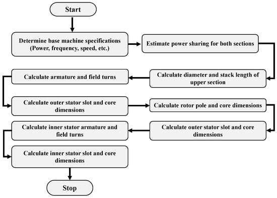
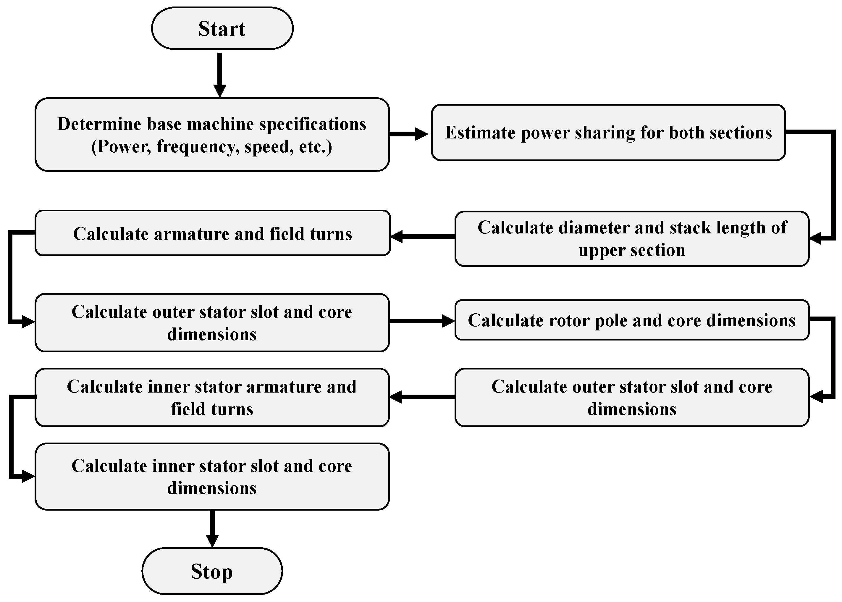
The DSWFFSM design methodology borrows elements of traditional electrical machine design from the literature, such as [16,17]. Furthermore, a lot of the design process is similar to that of a single-stator WFFSM. A basal design outline is given in Figure 1. In the flowchart, feedback loops are not used because of the optimization process considered in this paper, which will be discussed later. The various design sections are summarily discussed, with differences between this design process and that of a single-stator WFFSM highlighted.
Figure 1.
DSWFFSM design process.
2.1. Determining Machine Specifications
The design starts by determining the specifications of the proposed machine. Values for fixed machine parameters like the rated power, frequency and speed are determined at this stage. The choice of frequency and speed narrows the possible stator and rotor slot/pole combinations. Thus, the stator and rotor slot/poles would normally be determined at this stage. Rules for determining the stator and rotor poles are given in [18,19]. However, it should be noted that since the armature of a WFFSM in a wind turbine is connected to a fully rated power converter, the frequency need not be limited to the grid frequency. Winding parameters like stator voltages and field currents can also be determined at this stage.
2.2. Power Share
For immediate sizing purposes, the machine can be divided into two sections; the outer section containing the outer stator and the outer region of the rotor, and the inner section containing the inner stator and inner region of the rotor. The inner section occupies a smaller active volume, therefore it is expected to generate less power. As such, sizing calculations can be formulated considering the contributions of both sections.
This design approach is notably different from a single-stator WFFSM. It is somewhat similar to calculating the parameters of the rotor winding of a doubly fed induction generator [20]. Similarly, this power sharing will mostly affect the calculation of the winding parameters. However, the power sharing can be assumed to be equal, thereby simplifying the winding calculations. In this case, the same number of turns can be used for windings in the inner and outer stator. If significant saturation is observed, especially in the inner stator section, more stringent power sharing can be applied.
2.3. Air-Gap Sizing
The rotor’s outer diameter can be calculated using conventional approaches. The rotor outer diameter () should be calculated based on the power assigned to the outer section. If an equal power sharing is assumed, the outer rotor would be sized on half the machine-rated power. The outer rotor diameter can be calculated by the equation below [21].
where is the power assigned to the outer section, is the sheer stress, is the stack aspect ratio, and is the rated speed in radians. The stack length () is calculated as
Values for range from 0.2–1.5. Provisions should be made for the higher propensity of WFFSMs to be saturated, thus the sheer stress may be estimated to be slightly less than that of traditional machines.
2.4. Armature & Field Winding Parameters
In calculating the winding parameters for the armature, an appropriate voltage () rating is determined. The voltage can be based on many factors such as conductor type, the use of transformers, current level, etc. The number of armature turns per phase () is then calculated as
where is the electrical frequency of the armature, is flux per pole, and is the winding factor for the armature [17]. It is worth noting that the calculated number of turns can be adjusted within a reasonable range to modify the air-gap flux density.
For the field windings, a suitable rated field current () can be chosen, from which the number of turns in the DC field windings () can be calculated as in [22]
where is the rated peak air-gap flux density, g is the air-gap length, is the number of field poles, is the permeability of free space, and is the field winding’s winding factor.
2.5. Slot and Core Dimensions
There are different formulations for calculating the other geometric parameters of the machine such as pole heights and widths, core depths, etc. Some estimations are given in [23]. After calculating the rotor dimensions including pole and core heights, the inner stator diameter is basically the inner rotor diameter less two times the air-gap length. Once the inner stator diameter is known, the winding parameters can be calculated.
3. Design Optimization Process
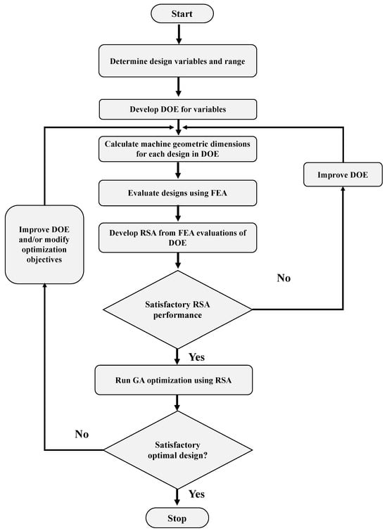
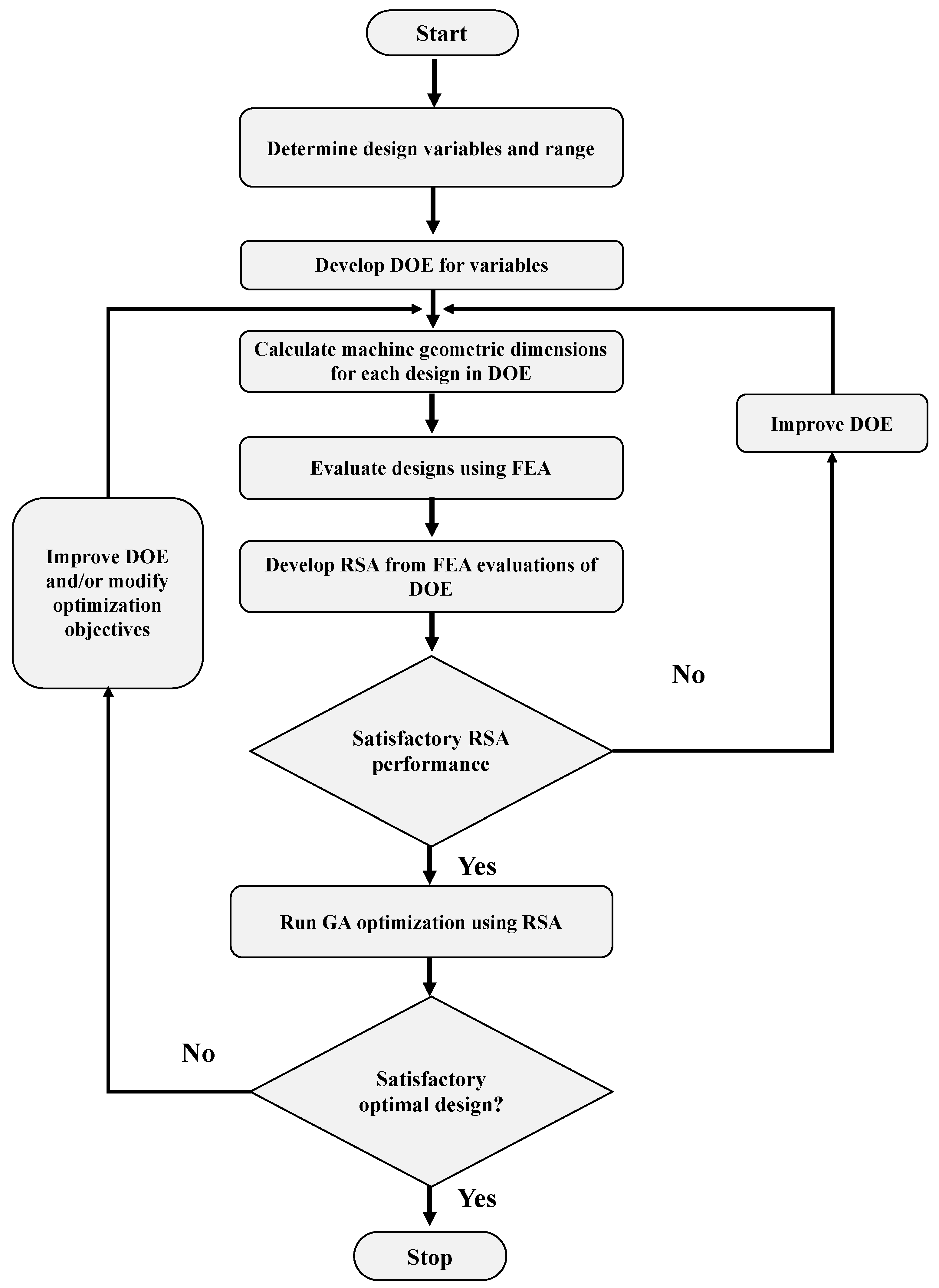
In the earlier highlighted design process, feedback loops are noticeably absent, as these are more beneficial in the design of well-established machines. Instead, an optimization process can be used to explore the design space of a desired machine. The proposed optimization process in this paper is outlined in Figure 2. The optimization process uses a multi-objective genetic algorithm coupled with a response surface approximation or surrogate model. This method of optimization is detailed in [24], and provides a quick exploratory method to optimize machine designs. It is particularly useful for lesser-known design spaces, as different designs can be inspected before even running an optimization.
Figure 2.
Design optimization procedure.
The first step is to outline considered design variables and desired objectives. An initial design of experiment (DOE) can be formulated with a limited number of designs to calibrate the practical range of selected variables. The geometric and winding design process presented in the earlier section is used to calculate the machine parameters needed in a finite element analysis (FEA) model. When suitable ranges have been determined, a comprehensive DOE can then be evaluated. In this paper, 2-D time stepping finite element analysis (FEA) models were used for evaluating designs. FEA models offer high accuracy which is very beneficial at initial design stages, helping to reduce design cycles and costs [25]. However, given the time-consuming nature of time stepping FEA models, partial models were used. Other accurate analytical methods can be used if available. It is just as important to note that saturation is a prevalent problem with flux modulation machines, as noted in [26]; thus it is recommended that the analytical technique be able to account for saturation. Although there are different sampling techniques used for DOEs, Latin hypercube sampling (LHS) is a commonly used method [24] because of its efficient mapping of the design space. This LHS method is adopted in this paper.
After all the designs in the DOE have been analyzed using FEA, a response surface approximation (RSA) is developed. The Kriging method is commonly recommended due to its capture of all the data in the DOE. Test designs that were not included in the DOE, but within the DOE range, can be fed into the RSA to test its accuracy. If the output approximations are satisfactory, the optimization process can proceed. However, if the approximations are far from actual values, the number of designs in the DOE can be increased. A hybrid DOE can also be formulated using complementary sampling methods for the additional designs to cover areas the LHS may have missed.
The DOE is formulated in MATLAB R2020a, while the FEA models are developed and simulated using Ansys EDT. The surrogate model and optimization processes are implemented using ANSYS Workbench 2024 R1. The performances at peak generating torque are considered for this optimization process. A “load angle” component is added to the armature excitation. Each design is monitored using a python script that shifts the “load angle” to achieve this required region of operation. Finally, the optimization process is used to maximize the output power, efficiency and power factor.
4. Design of a 3 MW Direct-Drive DSWFFSM
In this section, an optimized 3 MW direct drive DSWFFSM is presented. The design and optimization processes outlined in the previous sections are used to develop this design. However, there are some constraints imposed on the design that necessarily modify the proposed design procedure. The fixed parameters for this design process are listed in Table 1. The choice of poles and armature frequency is due to the desired speed. If a 50-Hz armature frequency is used, more poles will be required to achieve the desired speed, which increases complexity. Permanent-magnet flux-switching machines (PMFSMs) are touted as a high-torque-density topology [3]. Therefore, the permanent-magnet flux-switching machine (PMFSM) design in [27] is used as a benchmark. To this end, the outer stator outer diameter () and stack length () of the DSWFFSM design are fixed at values of the PMFSM design in [27]. Although the aspect ratio from [27] may not be optimal for the DSWFFSM, using this specific volume constraint provides a practical context for comparison. It should be noted that the M400-50A steel is used for the machine in the FEA evaluations.
Table 1.
Design fixed parameters.
4.1. Optimization Process of the 3 MW DSWFFSM
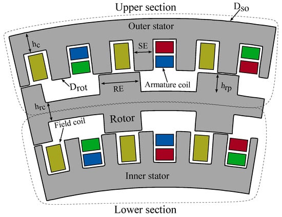
The design variables used in the optimization process and their considered ranges are given in Table 2, while the DSWFFSM model is illustrated with labeled dimensions in Figure 3. With the outer volume fixed, the outer rotor diameter sets the tone for the eventual generated power. Although the labeled in Figure 3 is actually the outer stator’s inner diameter, it is essentially a similar value to the actual , given the relatively negligible value of the air-gap length. Too small a diameter reduces the power generated, while too large a diameter reduces the space available for the stator core and can introduce significant saturation.
Table 2.
Optimization variables.
Figure 3.
Machine model geometry illustration.
Varying the field turns per slot is done to determine the optimal level of excitation possible for the machine while escaping diminishing returns in output. These diminishing returns manifest in the form of drops in efficiency and power factor, despite increases in the power generated. For simplicity, the same number of armature and field turns is used in both stators. The rotor design variables are critical factors in the modulation process, while the stator embrace determines the slot depth, which has implications for leakages and saturation.
For the initial DOE, 700 design combinations based on the variables and the Latin hypercube sampling method are evaluated. Considering the number of poles in the armature, field and rotor, the highest common factor is 8, thus an eighth of the machine is used in the FEA models. Conventional boundary conditions are used with a zero vector potential at the curved edge of an enclosing outer region, with independent and dependent boundaries at the straight edges of the fractional model. About 200,000 mesh elements are used for each model, and each model is simulated for 0.5 s at a time-step of 0.002 s. Averages of the desired output variables are obtained between 0.3–0.5 s.
Outputs like torque, losses and steel area are derived from the native transient reports in Ansys EDT, from which values like power generated, efficiency and steel mass can be determined. User-defined output variables in Ansys EDT are also used to determine the power factor. To determine the power factor, the input currents and induced voltages are transformed from the three-phase ABC planes to the d-q plane, from which the real and reactive powers are obtained.
As mentioned earlier, the Kriging response surface approximation method is used with a variable kernel variation type. For the multi-objective genetic algorithm optimization process, a population of 100 is used. The convergence stability percentage is 2% and a maximum of 20 iterations is set. The optimization has multi-objectives to maximize the power generated and efficiency as outlined below.
These are subject to the constraint of the power factor being greater than or equal to 0.76. While the power factor is an important aspect, it does not need to be constrained to a grid-compliant value. However, a machine with a low power factor would require a bigger converter, thus the constraint.
4.2. Optimization Result
From the initial DOE, the highest generated power was about 3.26 MW in a design with a 0.73 power factor and 92% efficiency. Although the power and efficiency are within the desired values, the power factor is too low. Nevertheless, this design is used as a baseline for a potential optimal design. An optimal design with an approximate 3.29 MW generated power, 91.5% efficiency and 0.78 power factor is initially selected. However, when this design is tested with an actual FEA model, the power generated drops to about 3.12 MW at 91.7% efficiency and 0.765 power factor. To reduce the 5.45% error between the estimated and calculated power generated, the RSA is fine-tuned by adding 50 extra designs within an identified range of interest, and a new optimization with the same objectives is conducted.
The design variables of the selected optimal design are given in Table 3, while the different output performance parameters for the optimized design are given in Table 4. From the RSA, the optimal design is estimated to generate 3.286 MW of power at 0.799 power factor and 92.2% efficiency. Thus, the RSA estimations have errors of 2.37% for the generated power, 0.62% for the power factor and 0.435% for the efficiency. Note that the efficiency error is the percentage error and not the difference in efficiency. Although the core depths of the new optimal design are outside the narrowed ranges, there was no need to further refine the RSA given the low error margins.
Table 3.
Optimal design variables.
Table 4.
Performance comparison.
The design is also compared with a single-stator WFFSM (SSWFFSM) design in Table 4. The SSWFFSM design is based on the outer stator and rotor of the optimized DSWFFSM design in Table 4. The consideration is that since this section is optimized for the DSWFFSM, the optimal variables for the DSWFFSM should apply to the SSWFFSM.
The optimized DSWFFSM generates slightly over 3 MW for the given field excitation at a power factor of 0.8. It is worth noting that the FEA models use current excitations for the armature windings, and this may lead to slightly different performances compared with using voltage excitations, especially in terms of power factor. In comparison, for the same volume, just under 2 MW of power is generated in the single-stator model, at the same power factor as the DSWFFSM. Therefore, the DSWFFSM can generate as much power within the given volume as the PMFSM in [27]. Although the power factor of the DSWFFSM is greater than the 3 MW PMFSM in [27], the efficiency of the PMFSM is significantly higher at 97.2%.
In [14], novel PM flux-intensifying machines are optimized for 3 MW at 15 rpm. The topology with the highest power density at 90 kW/m3 has a power factor of 0.76 and efficiency of 97%. The largest design has a power density of 73 kW/m3 at 0.9 power factor and 97.1% efficiency. These specific power values are around the range of the optimal DSWFFSM design. However, the 3 MW, 15 rpm PM Vernier generator in [15], with an efficiency of 97.3%, sports a significantly larger power density of 128 kW/m3, albeit at a notably lower power factor of 0.51.
From the optimal values in Table 3, the field turns and stator diameter are at the extreme of the given ranges. An even larger diameter would increase the power ceiling possible considering Equation (1). However, in this context of a fixed outer diameter, the core depth is reduced, which can result in saturation. Increasing the field turns increases the flux in the machine and its performance. However, further increases can easily cause many parts of the machine to be saturated and thereby degrade performance. A large stator pole embrace helps to limit saturation in the teeth, while an optimal rotor embrace is typically low. In [28], a rotor embrace close to 0.33 is recommended for flux reversal machines, and this value is close to the optimal value from the optimization. Narrower rotor pole embraces facilitate higher saliency which boosts torque production.
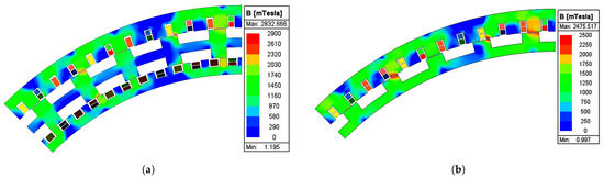
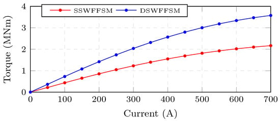
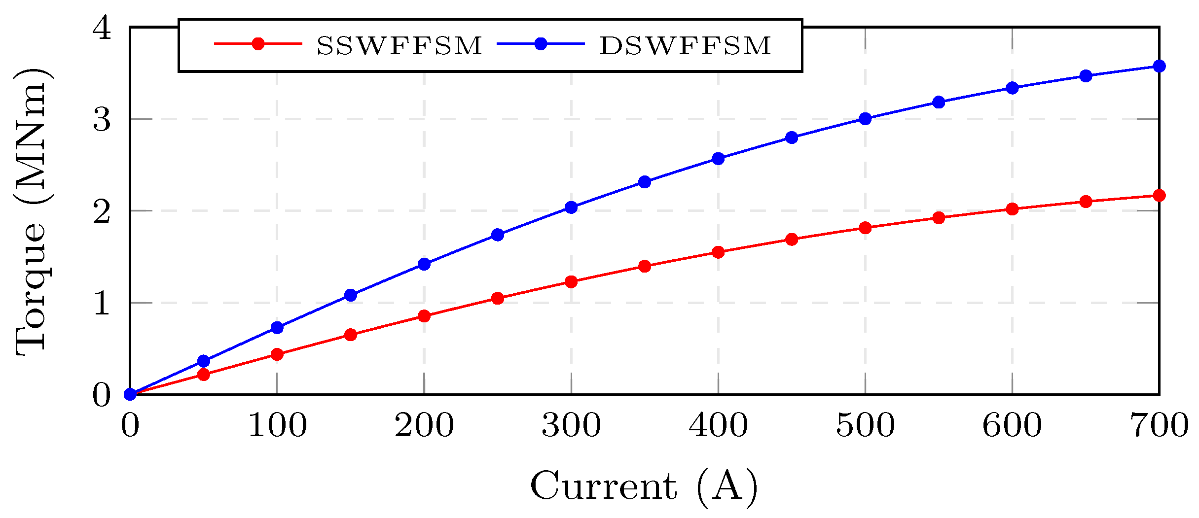
The FEA models of the DSWFFSM and SSWFFSM designs with flux density overlays are illustrated in Figure 4. Some level of saturation can be observed in parts of the optimized DSWFFSM illustrated in Figure 4a. Regions of the stator and rotor teeth are overlaid with flux density values beyond the saturation threshold for the M400-50A steel used. Although the maximum flux density recorded on the single-stator model in Figure 4b is less than that of the DSWFFSM in Figure 4a, there are only sparsely located hotspots with these high flux densities in Figure 4a. The change in generated torque at different loads is plotted in Figure 5 for the two designs. Both levels show similar responses to increasing load current, with saturation nonlinearities only evident at current values significantly higher than the rated armature current value of 333 A. This indicates that the overload capabilities of DSWFFSM are not inferior to those of the SSWFFSM, despite the increased flux in the rotor core from the inner stator.
Figure 4.
FEA models with flux overlays: (a) DSWFFSM design (b) SSWFFSM design.
Figure 5.
Torque at varying load current.
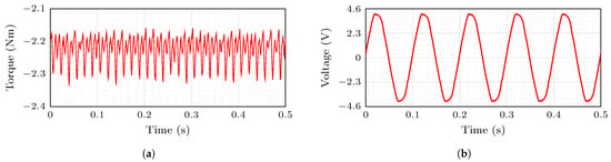
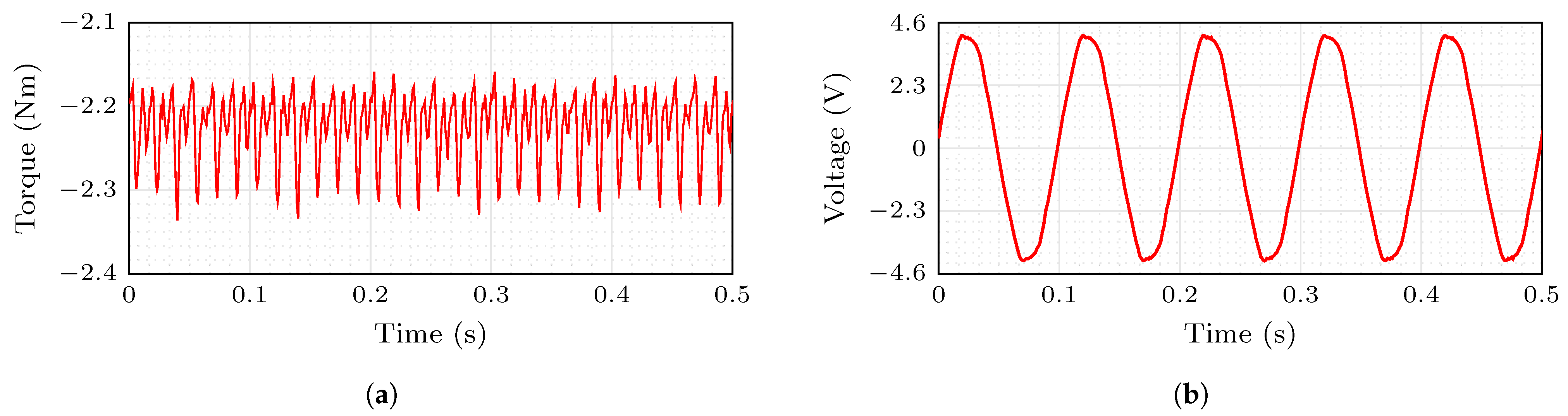
The generated torque and induced phase voltage of the DSWFSSM design are illustrated in Figure 6a and Figure 6b, respectively. As stated in Table 4, the DSWFFSM torque has a ripple of 7.3%, which is lower than that of the SSWFFSM at 14.3%, while the induced voltage has a total harmonic distortion value of 2.3%. The “dominant” harmonics in the induced voltage are the 5th and 7th harmonics, and they are likely a result of the concentrated nature of the armature windings. However, the voltage distortion is within permissible levels.
Figure 6.
FEA simulated parameters of DSWFFSM: (a) torque and (b) induced phase voltage.
5. Practicality Discussion
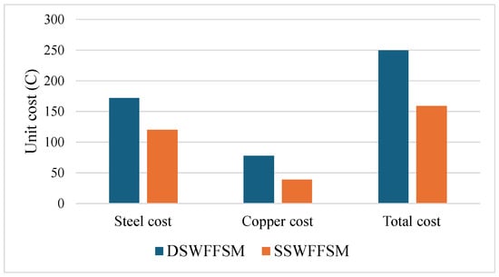
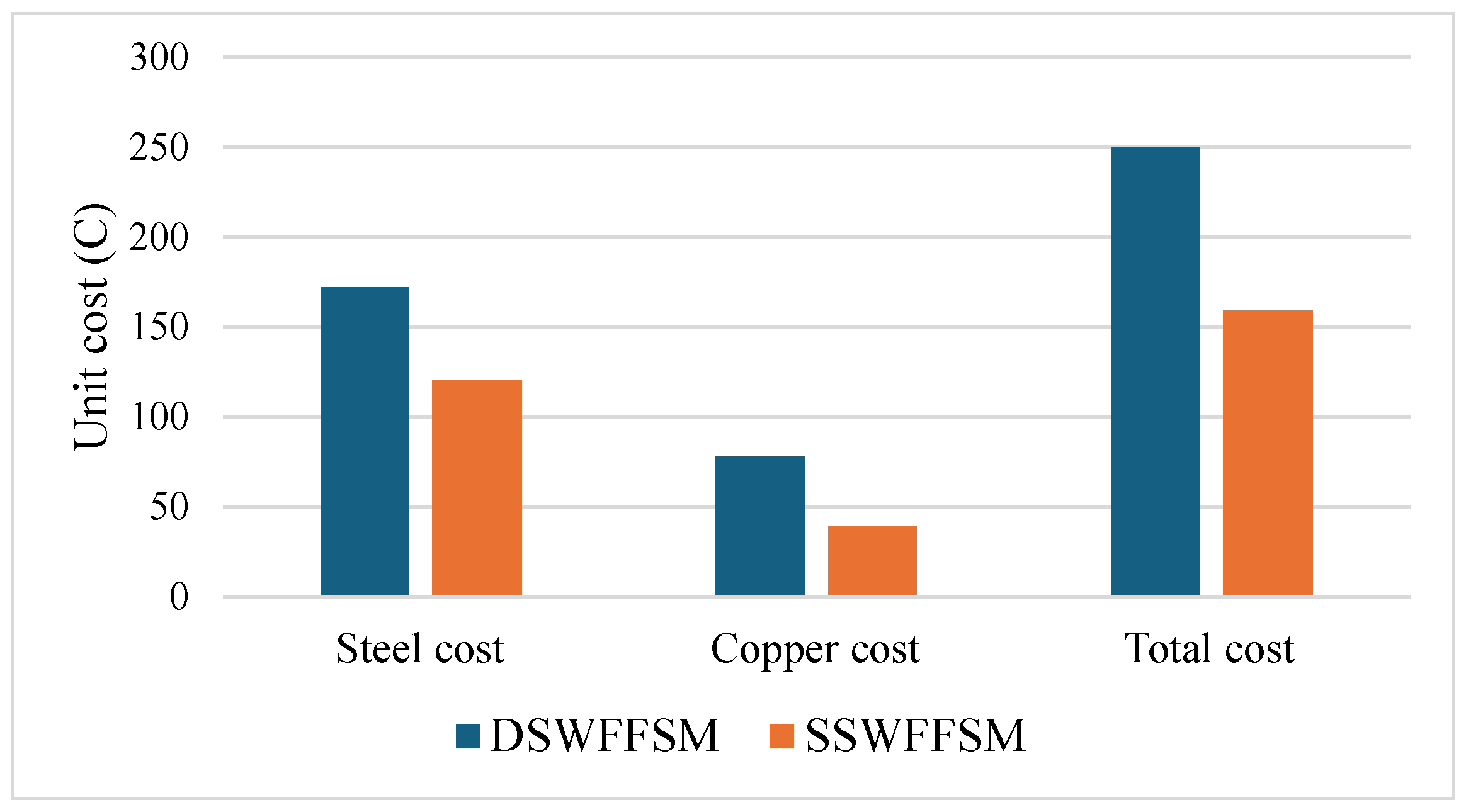
Assuming a M400-50A steel-to-copper cost ratio of 1:6 for a given currency [29,30], based on the masses of steel and copper needed, the relative costs of the DSWFFSM and SSWFFSM designs are illustrated in Figure 7. Naturally, the DSWFFSM is more costly, but the estimated cost of the SSWFFSM is approximately 64% of the cost of the DSWFFSM. This highlights the cost effectiveness of using a double stator. However, if the price ratio between the steel lamination material and copper further widens, this purported cost-effectiveness may be compromised.
Figure 7.
Cost comparison of the DSWFFSM and SSWFFSM designs.
With higher efficiency, the PMFSM would generate less heat compared to the DSWFFSM. However, this heat production would be concentrated around the stator. In the case of a DSWFFSM, the heat is distributed between the two stators. Nevertheless, considerations must be made for heat dissipation, especially for the inner stator which is covered by the rotor. The power sharing between both stators can be implemented to enable greater generation in the outer stator. The current density of the stator windings can be decreased to lower the wire resistance. The direct drive speed leads to a large machine that can easily accommodate bigger conductors.
Certain passive cooling methods are suggested for direct-drive systems in [31], such as using rectangular conductors to increase fill factor, using winding varnishing, or using a copper T-section heat pipe in the middle of slots to conduct heat out. The use of multipole configurations is also recommended, as this helps distribute the windings into many slots. With regards to this, it is worth noting that the proposed machine has multiple poles compared to conventional machines. Possibilities of liquid cooling also elicit further research. Finally, shorter stacks may provide short paths for heat conduction, so using lower stack aspect ratios () may be beneficial.
The low power factors in flux-switching machines compared to PM synchronous machines is a well-known characteristic [8]. This results in larger power converters required for their operations compared to conventional PM-excited machines. However, while PMs have unpredictable costs and inconsistent supply [32,33], the semiconductor technology used in power converters is improving, leading to a reduction in system costs. The efficiency of operations and lowered costs of components like cooling systems and passive components are listed in [34] to demonstrate the reduction of power converter costs. As a result, the cost of PMs is expected to surpass the extra costs that may be accrued from oversized power converters.
6. Conclusions
In this paper, DSWFFSMs have been shown to have power densities suitable for direct-drive wind turbines. With the double stator, the power output for an available volume is almost doubled compared to a single-stator model. The presented DSWFFSM design has a power density that matches that of some PM-based direct-drive machines from the literature. However, the efficiency of the DSWFFSM is significantly lower than the compared PM machines due to losses from the field windings. It also has a slightly lower efficiency than a single-stator WFFSM. DSWFFSMs have lower power factors compared to conventional PMSMs, and this means oversized power converters would likely be required for wind turbine operations. Finally, DSWFFSMs are shown to be a cost-effective topology, but further increases in copper prices can jeopardize this advantage over single-stator WFFSMs.
There are other aspects of the design of large DSWFFSMs that still require attention. Factors such as vibration from radial forces and harmonic distortion are worth investigating. Investigating the power sharing between the two stators in a bid to increase efficiency can be beneficial. The design process of DSWFSMs requires fine-tuning such that the design does not rely so much on optimization processes. This would require determining suitable saturation factors, electric and magnetic loadings, etc. The cooling of DSWFFSMs needs to be investigated, especially for the inner stator, as there will be a lot of heat from the losses. Finally, a comprehensive feasibility assessment is anticipated in the future for large-scale DWFFSMs in high-torque wind generator applications, considering the effects of gravitational and shear wind forces under dynamic conditions. This will include the design feasibility and structural analysis of a robust shaft-and-bearing system based on a scaled-down experimental prototype.
Author Contributions
Conceptualization: Z.S.M., formal analysis: Z.S.M. and O.I.O., funding acquisition: U.B.A. and O.M.P., investigation: Z.S.M., O.I.O., U.B.A. and O.M.P., project administration: U.B.A. and O.M.P., software: Z.S.M., O.I.O. and O.M.P., supervision: U.B.A. and O.M.P., validation: O.I.O., U.B.A. and O.M.P., visualization: Z.S.M. and O.I.O., writing—original draft: Z.S.M. and O.I.O., writing—review and editing: O.I.O., U.B.A. and O.M.P., All authors have read and agreed to the published version of the manuscript.
Funding
The APC was funded by Tshwane University of Technology.
Institutional Review Board Statement
Not applicable.
Informed Consent Statement
Not applicable.
Data Availability Statement
The data presented in this study are available on request from the corresponding author due to technical constraints regarding public repository storage.
Conflicts of Interest
The authors declare no conflicts of interest.
Abbreviations
The following abbreviations are used in this manuscript:
| Acronyms | ||
| DOE | Design of experiment | |
| DSWFFSM | Double-stator wound-field flux-switching machine | |
| DDWPG | Direct-drive wind power generation | |
| EESM | Electrically excited synchronous machine | |
| FEA | Finite element analysis | |
| LHS | Latin hypercube sampling | |
| PM | Permanent magnet | |
| PMFSM | Permanent-magnet flux-switching machine | |
| PMSM | Permanent-magnet synchronous machine | |
| RSA | Response surface approximation | |
| WFFSM | Wound-field flux-switching machine | |
| Design parameters | ||
| Rotor outer diameter | m | |
| Outer diameter of outer stator | m | |
| Sheer stress | N/m2 | |
| g | Air-gap length | mm |
| Stator core depth | mm | |
| Rotor core depth | mm | |
| Rotor pole height | mm | |
| Winding factor of field winding | ||
| Stack aspect ratio | ||
| Armature winding factor | ||
| Stack length | m | |
| Total number of field coils | ||
| Number of field coils per slot | ||
| Number of armature coils per phase | ||
| Number of armature poles | ||
| Number of field poles | ||
| Number of rotor poles | ||
| RE | Rotor pole embrace | |
| SE | Stator pole embrace | |
| Electromagnetic and mechanical parameters | ||
| Air-gap flux density | T | |
| Armature winding frequency | Hz | |
| Field current | A | |
| Permeability of free space | H/m | |
| Rotor mechanical speed | rpm | |
| Power generated in outer section | kW | |
| Armature flux per pole | Wb | |
| Armature phase voltage | V | |
References
- Dirma, V.; Neverauskienė, L.O.; Tvaronavičienė, M.; Danilevičienė, I.; Tamošiūnienė, R. The Impact of Renewable Energy Development on Economic Growth. Energies 2024, 17, 6328. [Google Scholar] [CrossRef] [Scilit]
- McKenna, R.; Lilliestam, J.; Heinrichs, H.U.; Wein, J.; Schmidt, J.; Staffell, I.; Hahmann, A.N.; Burgherr, P.; Burdack, A.; Bucha, M.; et al. System impacts of wind energy developments: Key research challenges and opportunities. Joule 2025, 9, 101799. [Google Scholar] [CrossRef] [Scilit]
- Chen, H.; Zuo, Y.; Chau, K.; Zhao, W.; Lee, C.H. Modern electric machines and drives for wind power generation: A review of opportunities and challenges. IET Renew. Power Gener. 2021, 15, 1864–1887. [Google Scholar] [CrossRef] [Scilit]
- Bensalah, A.; Benhamida, M.; Barakat, G.; Amara, Y. Large wind turbine generators: State-of-the-art review. In Proceedings of the 2018 XIII International Conference on Electrical Machines (ICEM), Alexandroupoli, Greece, 3–6 September 2018; pp. 2205–2211. [Google Scholar] [CrossRef] [Scilit]
- Nejad, A.R.; Keller, J.; Guo, Y.; Sheng, S.; Polinder, H.; Watson, S.; Dong, J.; Qin, Z.; Ebrahimi, A.; Schelenz, R.; et al. Wind turbine drivetrains: State-of-the-art technologies and future development trends. Wind Energy Sci. 2022, 7, 387–411. [Google Scholar] [CrossRef] [Scilit]
- Dong, Z.; Jiang, M.; Niu, S.; Chau, K. Overview of permanent magnet wind power generators. IEEE Trans. Magn. 2025, 61, 8102011. [Google Scholar] [CrossRef] [Scilit]
- Gyftakis, K.N.; Skarmoutsos, G.A.; Barajas-Solano, I.; Burchell, J.; Mueller, M. Critical Aspects of Demagnetization Faults in Multi-Stage Direct Drive Permanent Magnet Generators for Renewables. IEEE Trans. Ind. Appl. 2023, 59, 6655–6663. [Google Scholar] [CrossRef] [Scilit]
- Abunike, C.E.; Okoro, O.I.; Far, A.J.; Aphale, S.S. Advancements in flux switching machine optimization: Applications and future prospects. IEEE Access 2023, 11, 110910–110942. [Google Scholar] [CrossRef] [Scilit]
- Khan, F.; Sulaiman, E.; Ahmad, M.Z. Review of switched flux wound-field machines technology. IETE Tech. Rev. 2017, 34, 343–352. [Google Scholar] [CrossRef] [Scilit]
- Akuru, U.; Kamper, M. Presentation of novel high torque density dual-stator wound-field flux modulation machines. In Proceedings of the International Conference on Electrical Machines (ICEM); IEEE: Piscataway, NJ, USA, 2020; pp. 2026–2032. [Google Scholar]
- Ali, H.; Sulaiman, E.; Aziz, R.; Jenal, M.; Ahmad, M.Z.; Khan, F. Review of double stator flux switching machines with various arrangements of excitation sources. Alex. Eng. J. 2021, 60, 4393–4410. [Google Scholar] [CrossRef] [Scilit]
- Idoko, H.C.; Akuru, U.B.; Poopola, O. Consideration of Mutual Torque in Sizing of Double Stator Wound-Field Flux Switching Machine for Heavy-Duty Traction Motors. In Proceedings of the IEEE PES/IAS PowerAfrica; IEEE: Piscataway, NJ, USA, 2024; pp. 1–4. [Google Scholar]
- Khan, W.; Khan, F.; Ullah, W.; Akuru, U.B.; Zhao, W. Performance investigation of dual stator electrically excited flux switching machine. World J. Eng. 2025, 22, 1280–1289. [Google Scholar] [CrossRef] [Scilit]
- Mohammadi, A.; Badewa, O.A.; Chulaee, Y.; Lewis, D.D.; Essakiappan, S.; Manjrekar, M.D.; Ionel, D.M. Design Optimization of a Direct-Drive Wind Generator With a Reluctance Rotor and a Flux Intensifying Stator Using Different PM Types. IEEE Trans. Ind. Appl. 2024, 60, 6113–6123. [Google Scholar] [CrossRef] [Scilit]
- Padinharu, D.K.K.; Li, G.J.; Zhu, Z.Q.; Clark, R.; Thomas, A.S.; Azar, Z. System-Level Investigation of Multi-MW Direct-Drive Wind Power PM Vernier Generators. IEEE Access 2020, 8, 191433–191446. [Google Scholar] [CrossRef] [Scilit]
- Pyrhonen, J.; Jokinen, T.; Hrabovcova, V. Design of Rotating Electrical Machines; John Wiley & Sons: Hoboken, NJ, USA, 2013. [Google Scholar]
- Toliyat, H.A.; Kliman, G. Handbook of Electric Motors; CRC Press: Boca Raton, FL, USA, 2004. [Google Scholar]
- Nguyen, H.Q.; Jiang, J.Y.; Yang, S.M. Design of a wound-field flux switching machine with dual-stator to reduce unbalanced shaft magnetic force. J. Chin. Inst. Eng. 2017, 40, 441–448. [Google Scholar] [CrossRef] [Scilit]
- Jia, S.; Qu, R.; Li, J.; Li, D.; Lu, H. Design considerations of stator DC-winding excited vernier reluctance machines based on the magnetic gear effect. IEEE Trans. Ind. Appl. 2016, 53, 1028–1037. [Google Scholar] [CrossRef] [Scilit]
- Boldea, I. Variable Speed Generators; CRC Press: Boca Raton, FL, USA, 2005. [Google Scholar]
- Boldea, I.; Wang, C.; Nasar, S.A. Design of a Three-Phase Flux Reversal Machine. Electr. Mach. Power Syst. 1999, 27, 849–863. [Google Scholar] [CrossRef] [Scilit]
- Fitzgerald, A.E.; Kingsley, C., Jr.; Umans, S.D. Electric Machinery, 6th ed.; McGraw-Hill: Boston, MA, USA, 2003. [Google Scholar]
- Abunike, C.E.; Akuru, U.B.; Okoro, O.I.; Awah, C.C. Sizing, Modeling, and Performance Comparison of Squirrel-Cage Induction and Wound-Field Flux Switching Motors. Mathematics 2023, 11, 3596. [Google Scholar] [CrossRef] [Scilit]
- Bramerdorfer, G.; Tapia, J.A.; Pyrhonen, J.J.; Cavagnino, A. Modern electrical machine design optimization: Techniques, trends, and best practices. IEEE Trans. Ind. Electron. 2018, 65, 7672–7684. [Google Scholar] [CrossRef] [Scilit]
- Qiao, Z.; Jiang, D.; Fu, W. A Universal Parametric Modeling Framework for Electric Machine Design. Energies 2023, 16, 5897. [Google Scholar] [CrossRef] [Scilit]
- Mabhula, M.; Akuru, U.B.; Kamper, M.J. Cross-Coupling Inductance Parameter Estimation for More Accurate Performance Evaluation of Wound-Field Flux Modulation Machines. Electronics 2020, 9, 1748. [Google Scholar] [CrossRef] [Scilit]
- Lehr, M.; Dietz, D.; Binder, A. Electromagnetic design of a permanent magnet Flux-Switching-Machine as a direct-driven 3 MW wind power generator. In Proceedings of the IEEE International Conference on Industrial Technology (ICIT); IEEE: Piscataway, NJ, USA, 2018; pp. 383–388. [Google Scholar]
- Shi, J.T.; Liu, X.; Wu, D.; Zhu, Z.Q. Influence of Stator and Rotor Pole Arcs on Electromagnetic Torque of Variable Flux Reluctance Machines. IEEE Trans. Magn. 2014, 50, 1–4. [Google Scholar] [CrossRef] [Scilit]
- Huaxiao Alloy. How Much Does Electrical Steel Cost? 2025 Price Analysis by Grade. 2025. Available online: https://www.huaxiao-alloy.com/blog/how-much-does-electrical-steel-cost.html (accessed on 29 April 2026).
- Trading Economics. Copper-Price-Chart-Historical Data—News. 2026. Available online: https://tradingeconomics.com/commodity/copper (accessed on 29 April 2026).
- Taras, P.; Nilifard, R.; Zhu, Z.Q.; Azar, Z. Cooling Techniques in Direct-Drive Generators for Wind Power Application. Energies 2022, 15, 5986. [Google Scholar] [CrossRef] [Scilit]
- Smith, B.J.; Eggert, R.G. Costs, Substitution, and Material Use: The Case of Rare Earth Magnets. Environ. Sci. Technol. 2018, 52, 3803–3811. [Google Scholar] [CrossRef] [Scilit] [PubMed]
- Depraiter, L.; Goutte, S.; Porcher, T. Geopolitical risk and the global supply of rare earth permanent magnets: Insights from China’s export trends. Energy Econ. 2025, 146, 108496. [Google Scholar] [CrossRef] [Scilit]
- U.S. Department of Energy. Chapter 6: Innovating Clean Energy Technologies in Advanced Manufacturing. In Innovating Clean Energy Technologies in Advanced Manufacturing: Wide Bandgap Semiconductors for Power Electronics; Technical Report; Office of Energy Efficiency and Renewable Energy (EERE): Washington, DC, USA, 2016. [Google Scholar]

Disclaimer/Publisher’s Note: The statements, opinions and data contained in all publications are solely those of the individual author(s) and contributor(s) and not of MDPI and/or the editor(s). MDPI and/or the editor(s) disclaim responsibility for any injury to people or property resulting from any ideas, methods, instructions or products referred to in the content. |
© 2026 by the authors. Licensee MDPI, Basel, Switzerland. This article is an open access article distributed under the terms and conditions of the Creative Commons Attribution (CC BY) license.