


Abstract
This study focuses on the aerodynamic performance optimization of the SG6043 airfoil for application in small horizontal axis wind turbines (HAWTs) operating under low-Reynolds-number conditions. Recognizing the critical role of lift-to-drag ratio (Cl/Cd) in maximizing turbine power output, the research investigates the performance of SG6043 through design modifications and computational analysis. Initially, the baseline airfoil’s aerodynamic characteristics were verified using simulation tools like QBlade v0.96.3 software, confirming its previously reported performance. Subsequently, the airfoil was systematically modified by varying key parameters including thickness-to-camber ratio and angle of attack (AOA), operating at different Reynolds numbers. Among the modified versions, SG6043M5-7, SG6043M5-8, and SG6043M5-9 showed significant aerodynamic performance improvement, with SG6042M5-9 achieving the highest Cl/Cd ratio of 193.44 at Re = 6 × 10⁵ and AOA = 3.5°. The results demonstrated that a reduced thickness (5%) combined with moderate to high camber (7–9%) enhances the aerodynamic performance.
1. Introduction
Wind energy has emerged as a significant renewable resource due to its ability to generate clean and sustainable power for both small- and large-scale applications. In recent years, its global contribution has increased substantially, accounting for approximately 7.7% of total electricity generation and exceeding 2100 TWh annually (REN21, 2024). Despite this growth, the efficient extraction of wind energy is fundamentally limited by aerodynamic constraints [1]. In addition, small horizontal axis wind turbines (HAWTs), which are widely used in decentralized and low-wind-speed environments, often operate under low-Reynolds-number conditions (104–106). In this regime, viscous effects dominate the flow behavior, leading to early boundary layer separation, increased drag, and reduced lift-to-drag (CL/CD) ratios, thereby limiting turbine efficiency [2]. The aerodynamic performance of small HAWTs is primarily governed by blade design, which involves the selection of appropriate airfoils along with optimized chord and twist distributions. Among these parameters, the choice of airfoil plays a critical role in determining overall efficiency, particularly at low Reynolds numbers. Computational tools such as XFOIL and QBlade are widely used for evaluating aerodynamic characteristics and guiding airfoil selection and blade design optimization [3]. In the following sections a literature review is carried out focusing on developing high-performance low-Reynolds-number airfoils for small horizontal axis wind turbines to maximize power extraction. Ref. [4] analyzed airfoil aerodynamics in a subsonic wind tunnel, noting significant Cd and Cl changes between 9 and 15 degrees. A number of studies have investigated the aerodynamic performance of low-Reynolds-number airfoils for application in small-scale horizontal axis wind turbines (HAWTs), with particular emphasis on improving lift-to-drag ratios and blade efficiency. Ref. [5] demonstrated that SG-series airfoils (SG6040–SG6043) provide strong aerodynamic performance, with SG6043 achieving the highest CL/CD ratio of 125 at Re = 5 × 10⁵, indicating the effectiveness of optimized camber and thickness distributions. Similarly, computational studies comparing conventional airfoils such as NACA 6409 and NACA 4412 showed that cambered airfoils (e.g., NACA 4412) offer improved aerodynamic efficiency across a range of angles of attack [6]. Broader comparative analyses using tools such as QBlade have evaluated multiple airfoils, including SD7080, E387, and S1223, identifying SD7080 as particularly effective for low-wind-speed conditions [7].
In addition to airfoil selection, several studies have examined the impact of Reynolds number and angle of attack on aerodynamic behavior. Ref. [8] revealed that at low Reynolds numbers, drag increases significantly with angle of attack due to early flow separation, which directly affects turbine performance. These findings highlight the importance of selecting and designing airfoils that can maintain attached flow under low-speed conditions. From a blade design perspective, researchers have also explored the integration of multiple airfoils along the blade span to enhance performance. Ref. [9] proposed a design methodology using SG6040 and SG6041 airfoils at the hub and tip, respectively, with intermediate airfoils interpolated between them to achieve smooth aerodynamic transitions. Furthermore, the development of new airfoils specifically tailored for low-Reynolds-number applications has gained increasing attention. Ref. [10] introduced the UBD54-94 airfoil, which demonstrated superior lift-to-drag performance at Reynolds numbers between 3 × 10⁴ and 1 × 10⁵, making it suitable for blade tip regions. Ref. [11] developed the AF300 airfoil, which is optimized for improved startup performance and low-wind-speed operation in small wind turbines. Ref. [12] combined SG6043 with other airfoils to create SG6043_Eppler 422, achieving high aerodynamic performance for the Reynolds numbers typical of small HAWTs. Ref. [13] analyzed the NACA0018 airfoil using XFOIL software at Re = 5 × 10⁵, evaluating a wide range of angles of attack. Ref. [14] optimized blade geometry using SWRDC, achieving a peak power coefficient of 0.42 with the FX63-137 airfoil suitable for 11kW small wind turbines. Ref. [15] tested E387, FX 63-137, S822, S834, SD2030, and SH3055 airfoils in wind tunnels across Reynolds numbers of 1 × 10⁵ to 5 × 10⁵ [16].
Selig, M.S. et. al. introduced a family of low-Reynolds-number airfoils for small wind turbines, enhancing startup response and structural integrity, despite reduced maximum lift-to-drag ratios with increased thickness. Ref. [17] developed the T.Urban 10/193 airfoil achieving L/D of 95 at Re = 5 × 10⁵ with a 12° stall angle. Ref. [18] designed the Seagull airfoil, reaching max CL/CD ratios of 38, 52, and 57 at Re = 1 × 10⁵, 3.5 × 10⁵, and 6 × 10⁵ respectively. Ref. [19] developed the UBD6166 airfoil achieving max CL/CD of 66.9 at Re = 3×10⁵ for small wind turbines. Ref. [20] created the SG6043_Eppler 442 airfoil achieving max CL/CD of 80 at Re = 2.05 × 10⁵. Ref. [21] validated their blade profile through 2D CFD simulations. Ref. [22] analyzed the NACA 0012 airfoil noting increased lift at lower Re (2.21 × 10⁵) and reduced L/D at higher Re. Ref. [23] found max CL/CD for SG6043 at α = 2° using QBlade software. Ref. [24] used a k-ω SST turbulence model to simulate the S809 airfoil, noting discrepancies in lift and drag coefficients compared to experiments. Ref. [25] investigated NACA 4-digit airfoils at Re = 3.6 × 10⁵, observing effects of camber ratio on lift-to-drag ratios. Ref. [26] analyzed high-performance airfoils through XFOIL at Re = 3 × 10⁵, achieving max CL/CD ratios of 134, 131, and 127. Ref. [27] studied E387, RG15, and SD6060 airfoils across Reynolds numbers 5 × 10⁵, optimizing CL/CD ratios. Ref. [28] optimized NACA 4-digit, PARSEC, and Bezier curve airfoil coordinates at low Reynolds numbers. Ref. [29] evaluated the aerodynamic performance of three modified SG6043 airfoils, EYO7-8, EYO8-8, and EYO9-8, across Reynolds numbers from 1 × 10⁵ to 5 × 10⁵. In the latter study, EYO7-8 achieved the highest lift-to-drag ratio of 170 at Re = 5 × 10⁵. Ref. [30] optimized SG6043 for small wind turbines within a Reynolds number range of 1 × 10⁵ to 6 × 10⁵ by varying the thickness-to-camber (t/c) ratio between 0.5 and 1.5. SG6043 modified 1 reached a maximum CL/CD of 184.85 at Re = 6 × 10⁵. Refs. [31,32,33] evaluated the performance of four airfoils; NACA 4412, SG6043, SD7062 and S833 using QBlade. Authors found that the overall power coefficient (Cp) of NACA 4412 different tip speed ratios is higher than that of the other three airfoils.
Literature review reflected that many studies were carried out for designing new airfoils for low-Reynolds-number small horizontal axis turbine (HAWT). The challenge lies in selecting and optimizing an airfoil that offers a high lift-to-drag ratio while ensuring stable performance across varying conditions such as thickness-to-camber ratio, angle of attack (AOA), and Reynolds number. The SG6043 airfoil, known for its high performance in certain applications, needed to be tailored and optimized to meet the specific requirements of small HAWTs. However, achieving this optimization requires rigorous analysis and validation, both computationally and experimentally, to ensure that the modified airfoil performs efficiently in real-world wind conditions. Thus, the challenge is to optimize the design of the SG6043 airfoil for small HAWTs, ensuring enhanced aerodynamic performance. This research provides a comprehensive foundation for the development and implementation of optimized SG6043 airfoils in small wind turbine applications, contributing significantly to the advancement of efficient renewable energy technology.
2. Materials and Methods
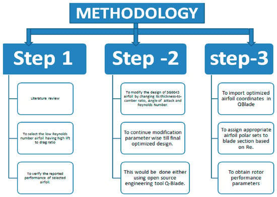
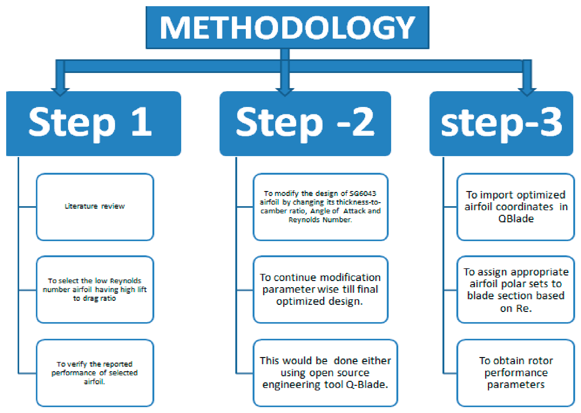
Figure 1 presents the overall methodology adopted in this study, structured into three main steps. In Step 1, a comprehensive literature review is conducted to identify airfoils suitable for low-Reynolds-number applications. Step 2 focuses on modifying the selected airfoil geometry by adjusting key parameters such as thickness-to-camber ratio, angle of attack, and Reynolds number to achieve an optimized design. The iterative process continues until a final optimized configuration is obtained using tools such as QBlade. In Step 3, the optimized airfoil is implemented to evaluate blade performance and rotor characteristics under specified operating conditions.
Figure 1.
Flow diagram of methodology.
2.1. Selection of Airfoil
Step 1. Literature Review
A comprehensive literature review was conducted to identify airfoils that perform well at low Reynolds numbers (typically 104–105, etc.), which are common in:
- Small wind turbines.
- Unmanned aerial vehicles (UAVs).
- Low-speed aerodynamic applications.
The main selection criterion was a high lift-to-drag ratio (CL/CD), since it directly indicates aerodynamic efficiency.
Step 2. Identification of Suitable Airfoil
From the reviewed studies, the SG6043 airfoil was selected because:
- It exhibits high lift coefficient (CL) at low Reynolds numbers.
- It maintains relatively low drag coefficient (CD).
- It shows good aerodynamic stability in low-speed regimes.
- It is widely reported as suitable for small wind turbine blades and UAV wings.
Step 3. Baseline Airfoil Data Collection
The following baseline aerodynamic data for SG6043 were gathered from the published literature:
- Lift coefficient (CL).
- Drag coefficient (CD).
- Lift-to-drag ratio (CL/CD).
- Performance across different angles of attack.
- Reynolds number operating range.
This data serves as a reference for validation.
Step 4. Computational Verification Using Q-Blade
The aerodynamic characteristics of the SG6043 airfoil were verified using Q-Blade. The airfoil coordinates were imported, and simulations were performed over a range of Reynolds numbers and angles of attack. Within Q-Blade, aerodynamic loads were calculated using Blade Element Momentum (BEM) theory, which combines sectional airfoil data with momentum theory to estimate lift and drag along the blade span. The key outputs extracted from the simulations included the lift coefficient (CL), drag coefficient (CD), and the lift-to-drag ratio (CL/CD).
Step 5. Validation of Results
The simulation results obtained from Q-Blade were compared with:
- Published experimental data.
- Existing aerodynamic databases.
This ensured that the computational setup was accurate before proceeding to design modification.
2.2. Design Modification
After validating the baseline airfoil, parametric modifications were performed.
Step 6. Identification of Design Parameters
The following parameters were selected for modification:
- Thickness-to-camber ratio.
- Angle of attack (AoA).
- Reynolds number (Re).
Each parameter influences aerodynamic behavior differently.
Step 7. Parametric Variation—One Parameter at a Time
To clearly understand individual effects, parameters were varied independently:
(a) Thickness-to-Camber Ratio Variation
- Increased and decreased thickness.
- Modified camber distribution.
- Observed changes in CL, CD, and stall characteristics.
Purpose:
- Increase lift without significantly increasing drag.
- Improve structural feasibility.
(b) Angle of Attack (AoA) Variation
- AoA was varied incrementally (e.g., from −5° to +10°).
- CL, CD, and CL/CD were plotted against AoA.
- Stall angle was identified.
Purpose:
- Determine optimal operating AoA.
- Maximize aerodynamic efficiency.
(c) Reynolds Number Variation
- Simulations were conducted at multiple Reynolds numbers.
- Performance trends at low Re were analyzed.
Purpose:
- Evaluate performance stability across operating conditions.
- Ensure suitability for low-speed applications.
Step 8. Iterative Optimization
The design was refined iteratively:
- Modify parameters.
- Run simulation.
- Compare CL/CD improvement.
- Check aerodynamic stability.
- Repeat until performance converges.
Step 9. Final Performance Evaluation
The optimized airfoil was evaluated for:
- Maximum lift coefficient.
- Minimum drag coefficient.
- Maximum CL/CD ratio.
- Stall angle behavior.
- Stability trends.
The final design was selected based on the best overall aerodynamic performance.
2.3. Simulation Setup and Operating Conditions
The performance of the SG6043 airfoil and its modified versions were analyzed using the state-of-the-art wind turbine simulation code, QBlade, which provides a modular set of highly efficient solvers for aerodynamic analysis. The inlet velocity was defined to correspond to a Reynolds number range of 100,000 to 600,000, representing the low-Reynolds-number regime typically encountered in small horizontal axis wind turbines. Simulations were conducted for angles of attack ranging from 0° to 10° to evaluate the lift-to-drag characteristics of the airfoil. Air properties were assumed to be constant, with a density of 1.225 kg/m3 and a dynamic viscosity of 1.789 × 10⁻⁵ kg/(m·s).
3. Results
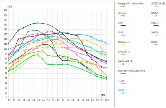
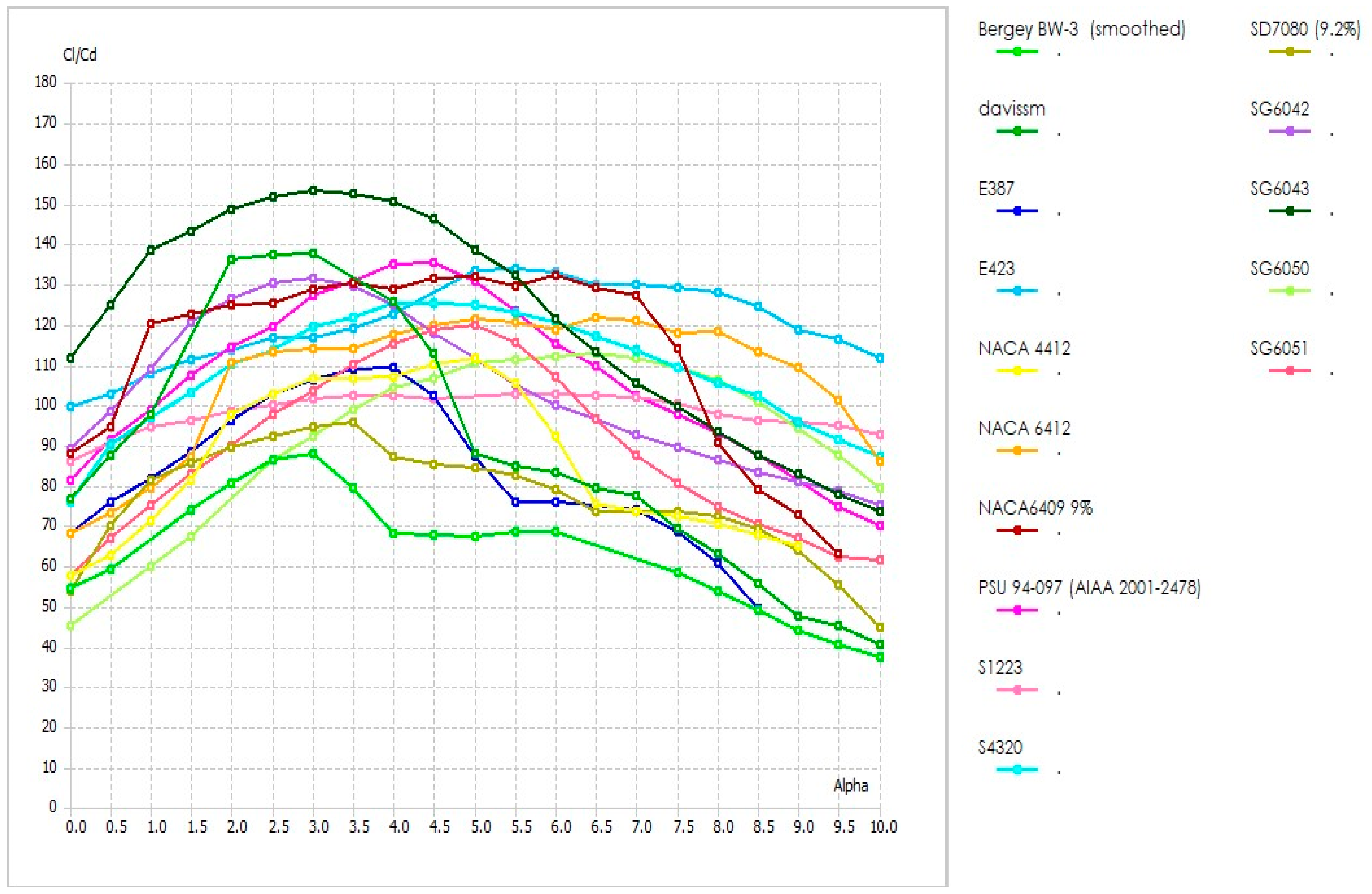
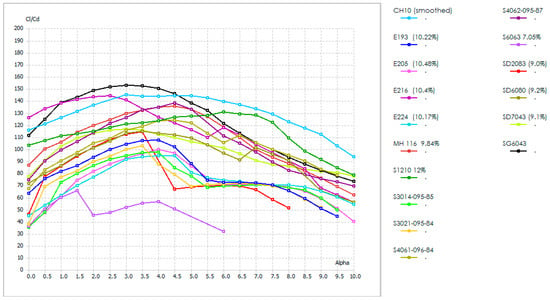
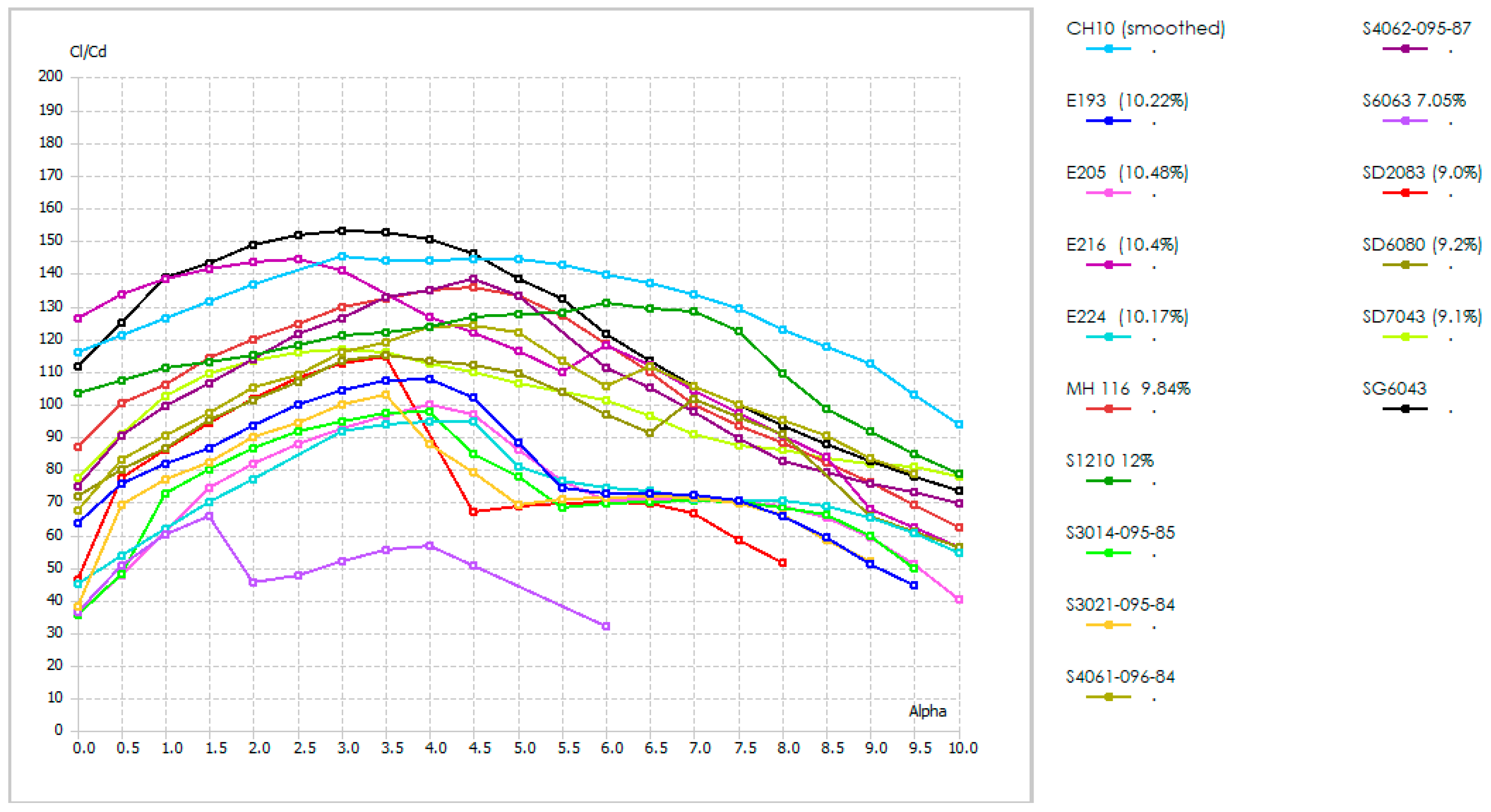
Thirty airfoils, including PSU94-097, NACA6409, NACA4412, NACA 6412, BW-3, DAVISM, SG6042, SG6043, SG6050, SG6051, EPPLER 193, E387, E423, E216, E224, E205, S4320, S1210, S1223, S4061, S4062, S3014, S6063, S3021, SD7080, SD6080, SD7043, SD2083, MH 116, and CH10 (smoothed) were selected for analysis. These airfoils were chosen based on their good performance at low Reynolds numbers for HAWT. The lift-to-drag ratios of all thirty airfoils have been evaluated using Q-Blade. Figure 2 and Figure 3 show the CL/CD ratios of the airfoils. The highest CL/CD of 152.88 has been observed for SG6043 at a Reynolds number of 6 × 10⁵. The SG6043 airfoil was identified as the most efficient and was selected for further optimization.
Figure 2.
CL/CD vs. AOA of high-performance low-Reynolds-number airfoils based on literature review.
Figure 3.
CL/CD vs. AOA of high-performance low-Reynolds-number airfoils based on literature review.
3.1. Airfoil SG6043
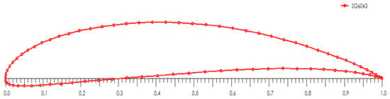
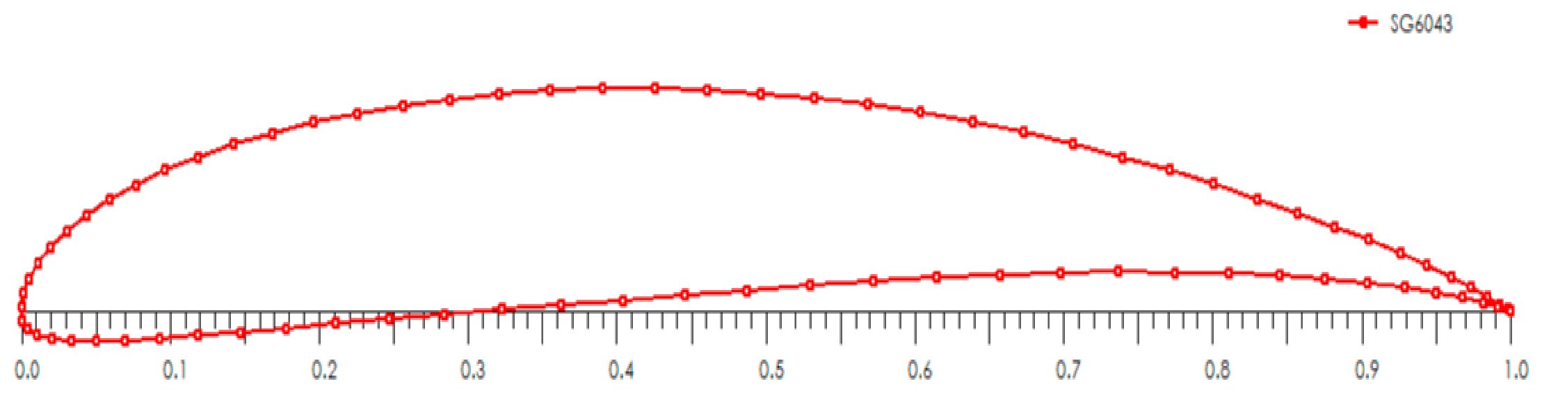
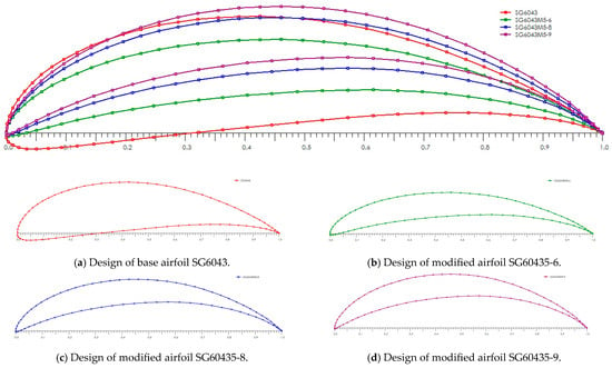
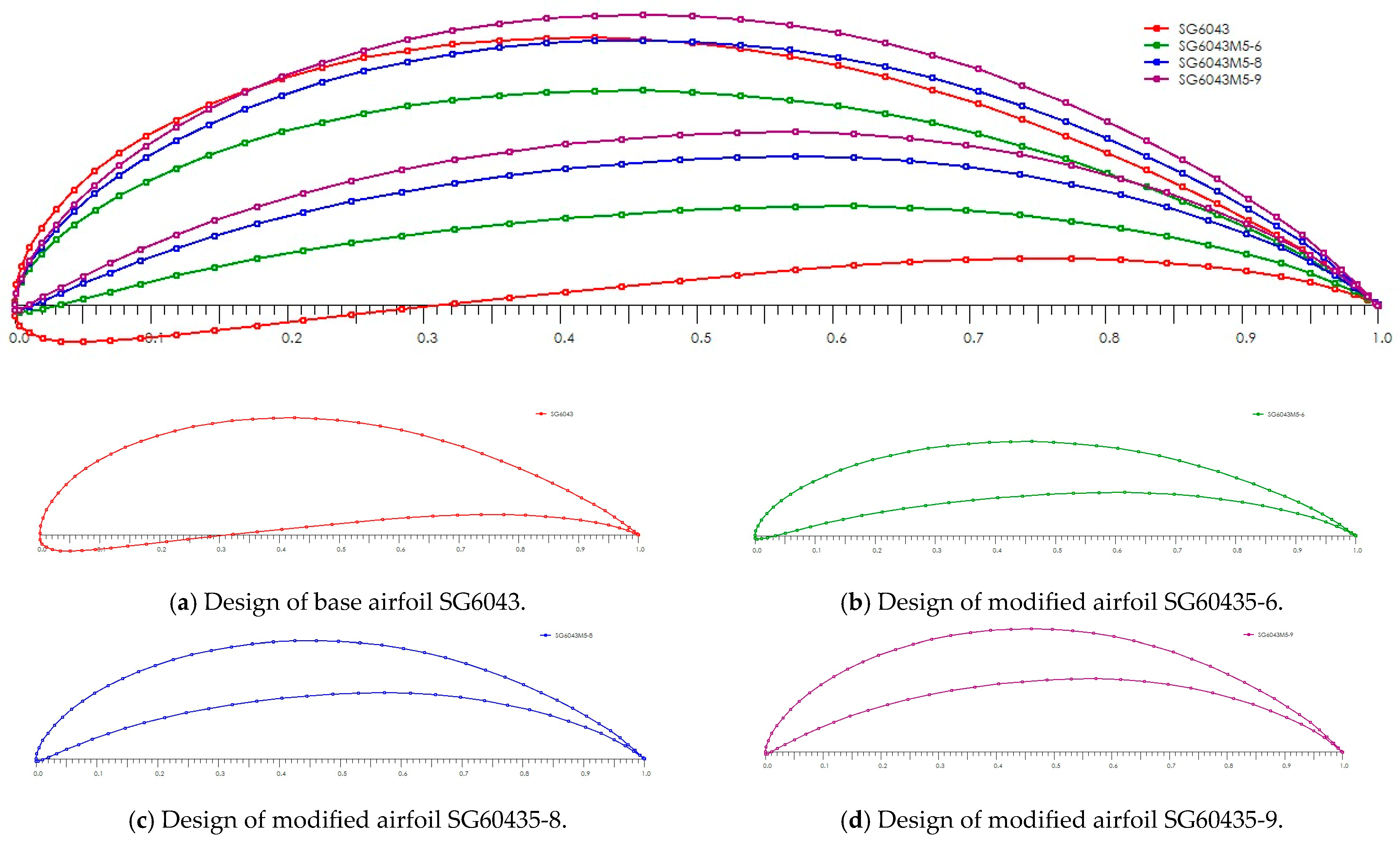
Figure 4 shown SG6043 airfoil is a low-Reynolds-number airfoil designed for efficient performance in small-scale aerodynamic applications such as UAVs, model aircrafts, and mini wind turbines. It features a maximum thickness of 10% at 32.1% chord and a maximum camber of 5.1% at 53.3% chord, which helps to generate significant lift at low angles of attack.
Figure 4.
Selected airfoil SG6043.
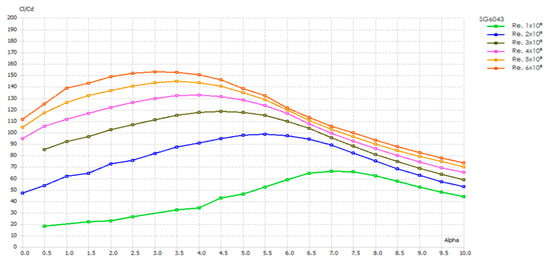
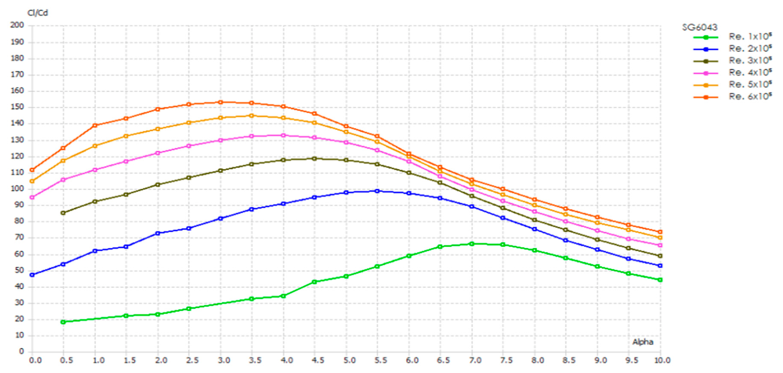
Table 1 and Figure 5 reflect the aerodynamic performance of the base airfoil SG6043 at low Reynolds numbers ranging from 1 × 10⁵ to 6 × 10⁵. The data shows that as the Reynolds number increases, the lift-to-drag ratio (CL/CD) improves considerably, which is 152.88 at a Reynolds number of 6 × 10⁵ and an angle of attack of 3°. The SG6043 airfoil performs most efficiently with increasing Reynolds number and moderate angles of attack.
Table 1.
Lift to drag ratio of selected airfoil SG6043 at Re. 1 × 10⁵ to 6 × 10⁵.
Figure 5.
Shows lift to drag ratio of selected airfoil SG6043 at Re. 1 × 10⁵ to 6 × 10⁵.
Validation of Reported Performance of Selected Airfoil SG6043
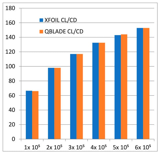
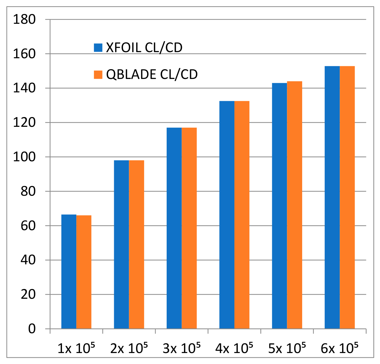
Table 2 and Figure 6 show the comparison between the maximum lift-to-drag ratio (CL/CD) and the corresponding angle of attack (AOA) for the SG6043 airfoil at various Reynolds numbers obtained through XFOIL and Q-Blade. The results verify that the performance of the SG6043 airfoil through Q-Blade and XFOIL is consistent with the available data.
Table 2.
Validation of reported XFOIL performance of SG6043 with Q-Blade.
Figure 6.
Validation of reported XFOIL performance of SG6043 with Q-Blade.
3.2. Modification and Optimization
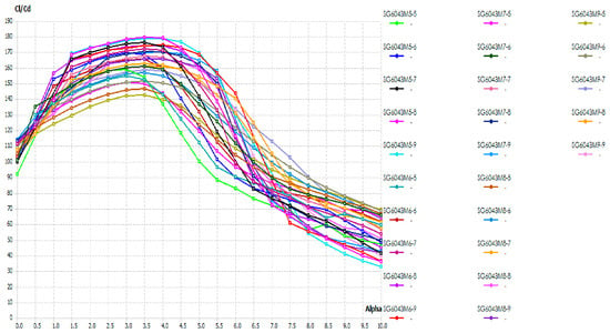
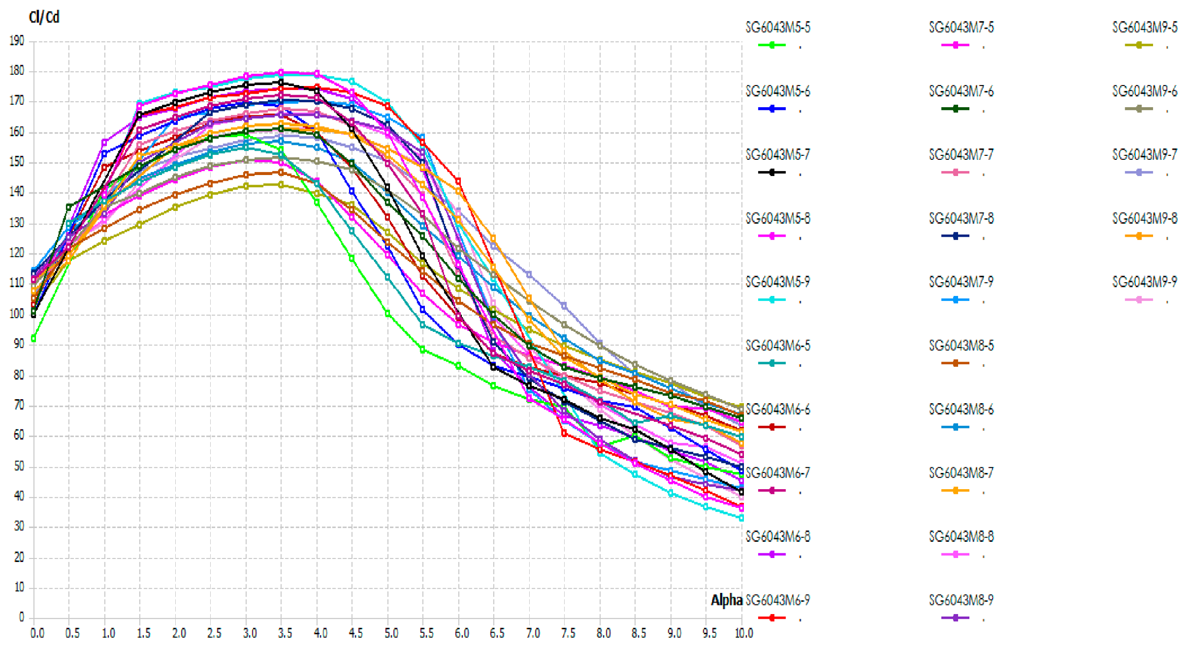
Following the methodology, 25 modifications were carried out to achieve an optimized design. The modifications are based on variations in thickness-to-camber ratio, angle of attack (AOA), and Reynolds number. The modifications were made by altering the thickness (5% to 9%) and camber (5% to 9%) of the base airfoil SG6043 at low Reynolds numbers ranging from 1 × 10⁵ to 6 × 10⁵.
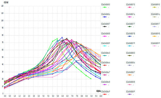
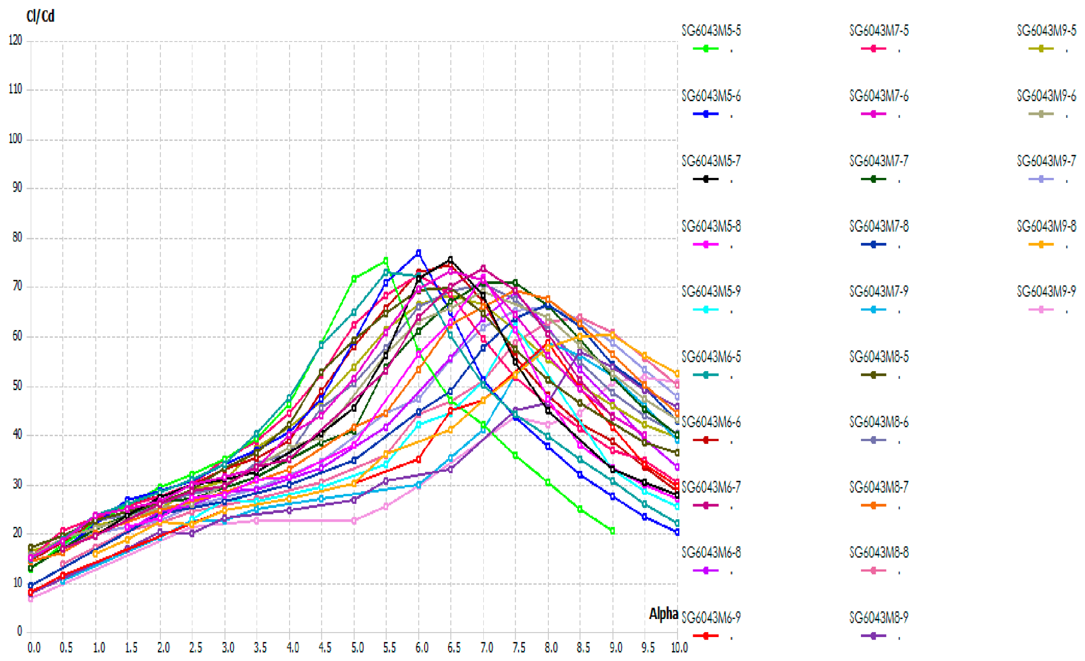
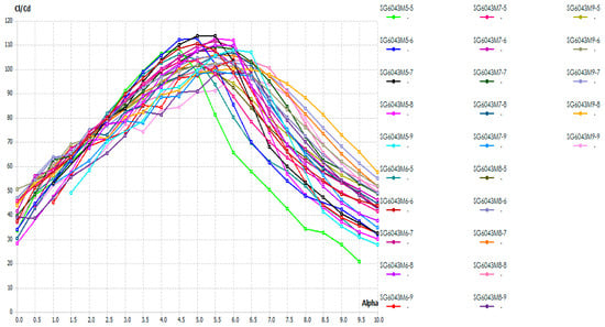
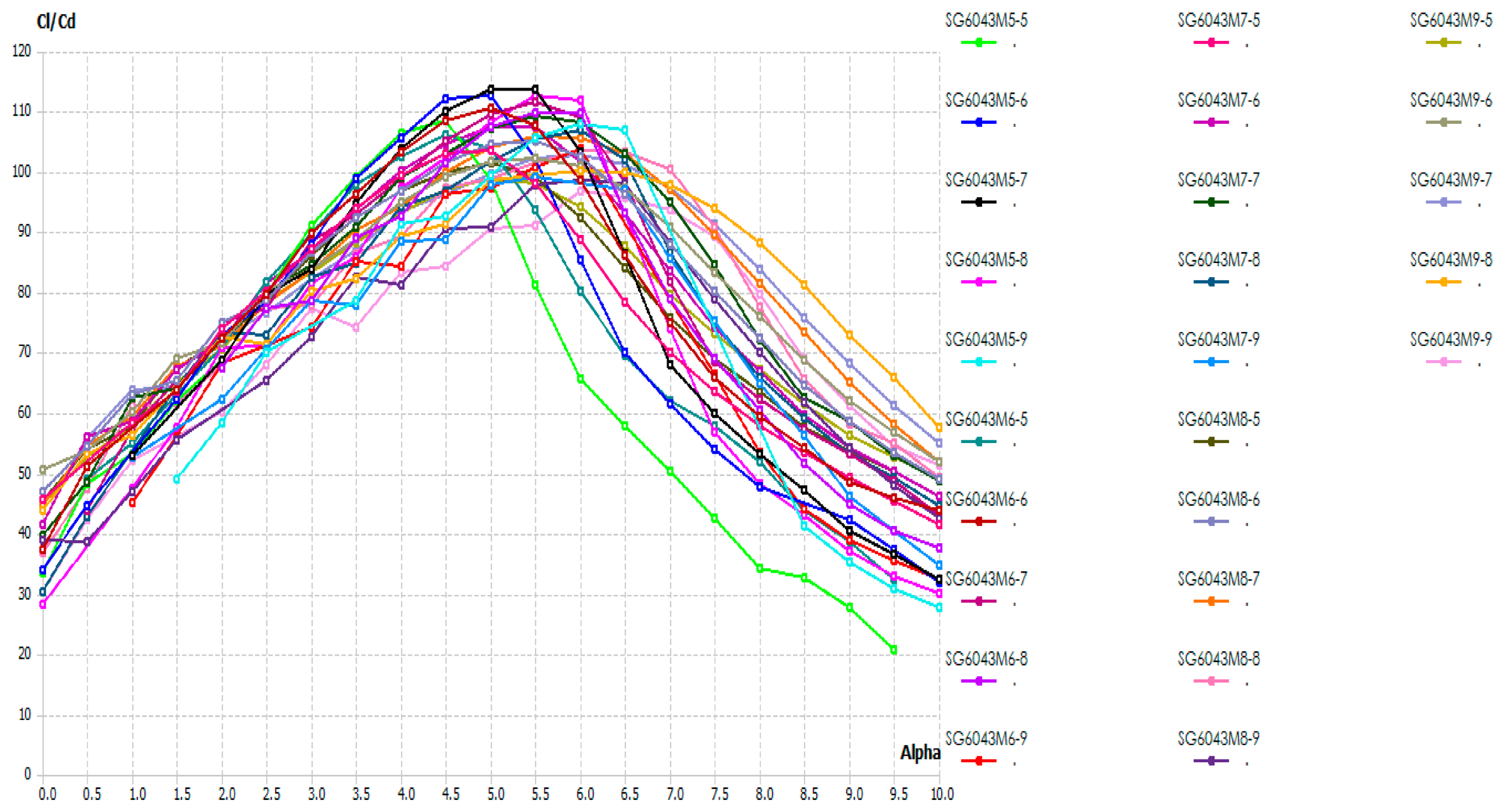
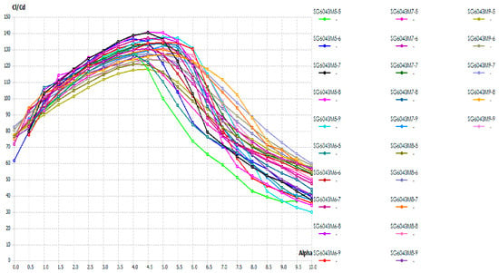
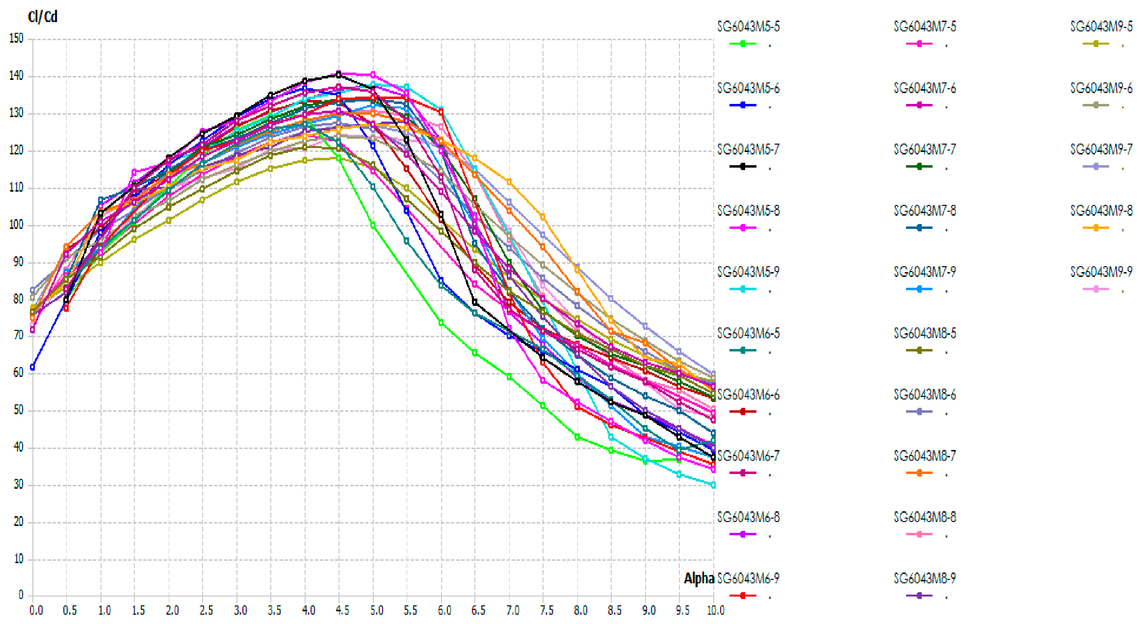
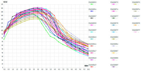
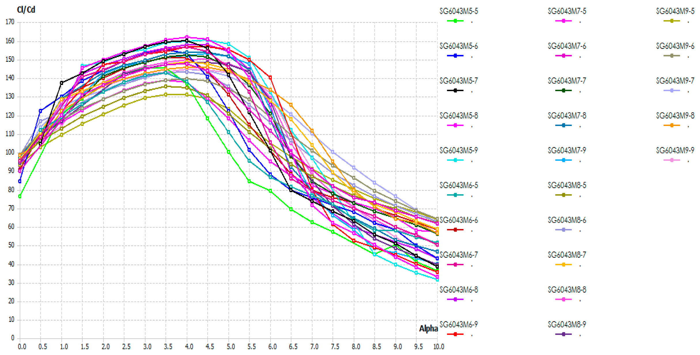
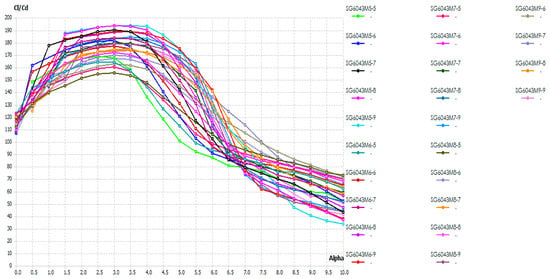
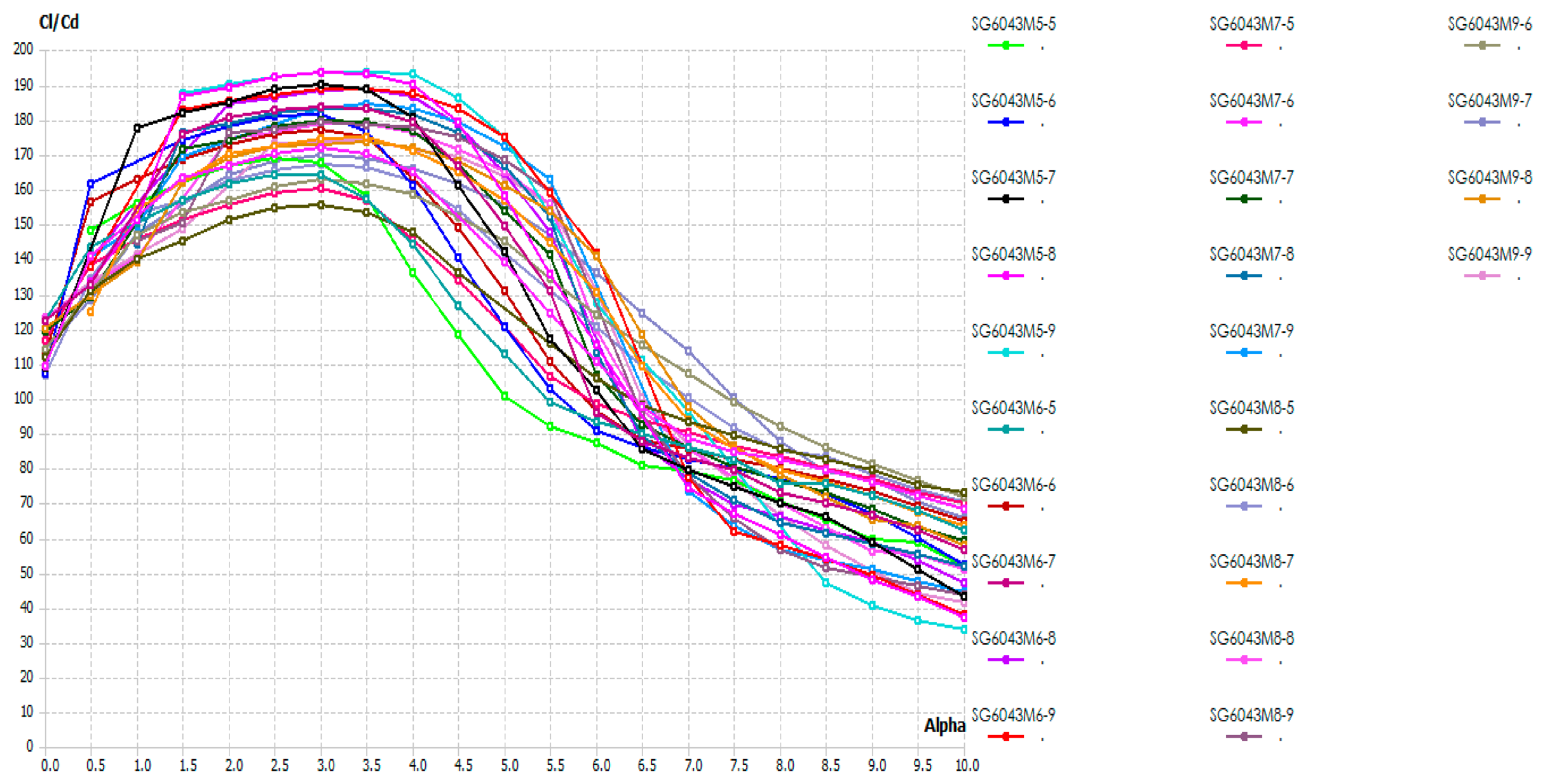
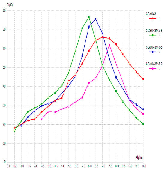
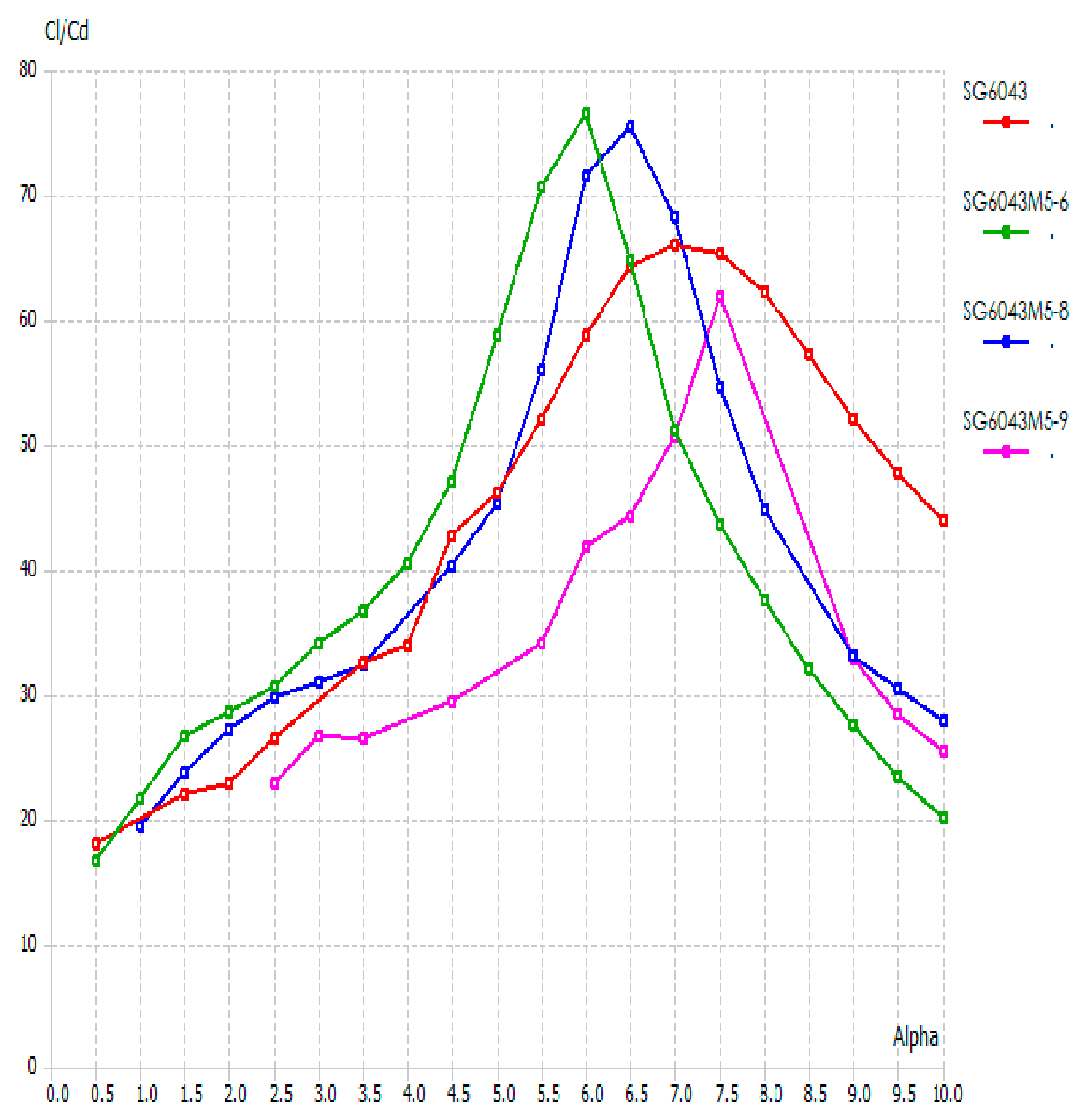
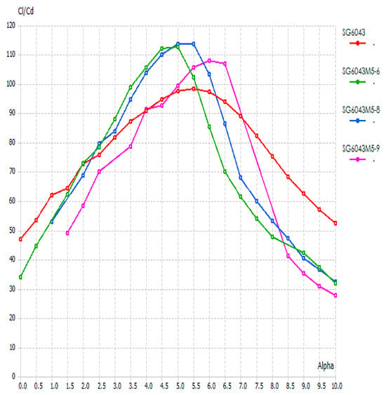
Figure 7, Figure 8, Figure 9, Figure 10, Figure 11 and Figure 12 presented the aerodynamic performance of the various SG6043 airfoil modifications evaluated at Reynolds numbers ranging from 1 × 10⁵ to 6 × 10⁵.At the lower Reynolds numbers of 1 × 10⁵ and 2 × 10⁵, the modified airfoil SG6043M5-6 demonstrated the most favorable aerodynamic characteristics. It attained the highest lift-to-drag CL/CD ratios of 76.48 at an angle of attack of 6° and 112.31 at an angle of attack of 5°, respectively, surpassing all other modifications.
Figure 7.
CL/CD vs. AOA of all modified airfoils at Re. 1 × 10⁵.
Figure 8.
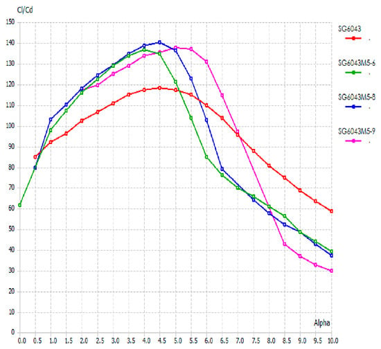
CL/CD vs. AOA of all modified airfoils at Re. 2 × 10⁵.
Figure 9.
CL/CD vs. AOA of all modified airfoils at Re. 3 × 10⁵.
Figure 10.
CL/CD vs. AOA of all modified airfoils at Re. 4 × 10⁵.
Figure 11.
CL/CD vs. AOA of all modified airfoils at Re. 5 × 10⁵.
Figure 12.
CL/CD vs. AOA of all modified airfoils at Re. 6 × 10⁵.
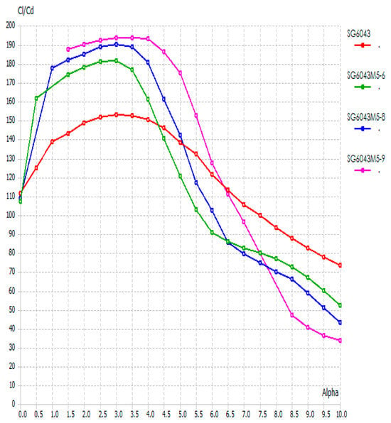
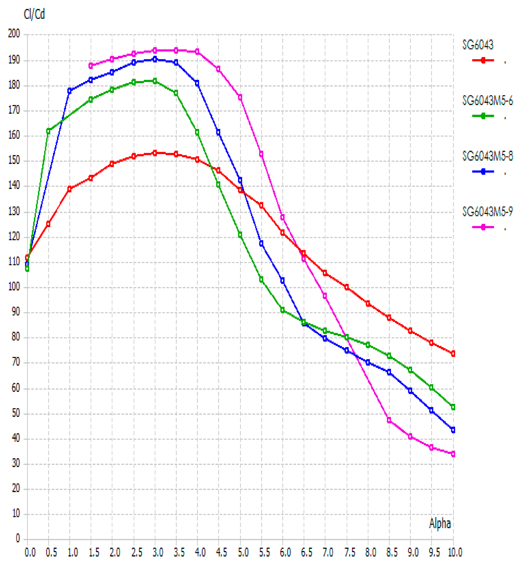
As the Reynolds number increased, the aerodynamic performance increased. At Reynolds numbers ranging from 3 to 5 × 10⁵, the SG6043M5-8 variant consistently outperformed the others. It achieved maximum CL/CD ratios of 140.55 at AOA 4.5°, 161.86 at AOA 4°, and 179.11 at AOA 3.5°, highlighting its superior efficiency in mid-range flow conditions. At the highest low Reynolds number of 6 × 10⁵, the SG6043M5-9 modification emerged as the best performer, reaching the peak CL/CD ratio of 193.44 at an AOA of 3.5°.
Overall, the results indicated that the optimal airfoil modification shifts with Reynolds number: SG6043M5-6 dominates at lower Reynolds numbers, SG6043M5-8 excelled in the mid-range, and SG6043M5-9 achieves maximum efficiency at higher Reynolds numbers.
3.3. Optimized Design
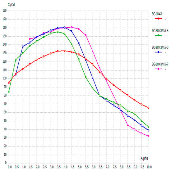
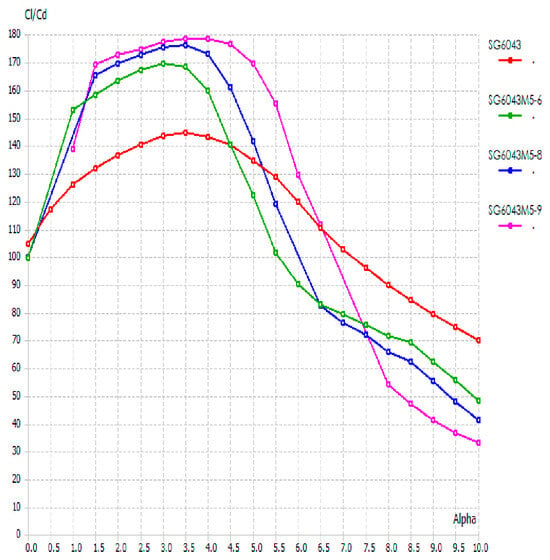
The results shown in Table 3 and Figure 13, Figure 14, Figure 15, Figure 16, Figure 17, Figure 18 and Figure 19 highlight the impact of camber variation on the aerodynamic performance of the SG6043 airfoil at low Reynolds numbers, specifically focusing on lift-to-drag ratio (CL/CD) against angle of attack (AoA). The study effectively demonstrated that even small geometric modifications in camber from 6% to 9% while keeping a constant thickness of 5% can significantly influence the aerodynamic efficiency across different flow regimes.
Table 3.
Highest lift to drag ratio modified airfoils.
Figure 13.
High lift to drag ratio modified airfoils.
Figure 14.
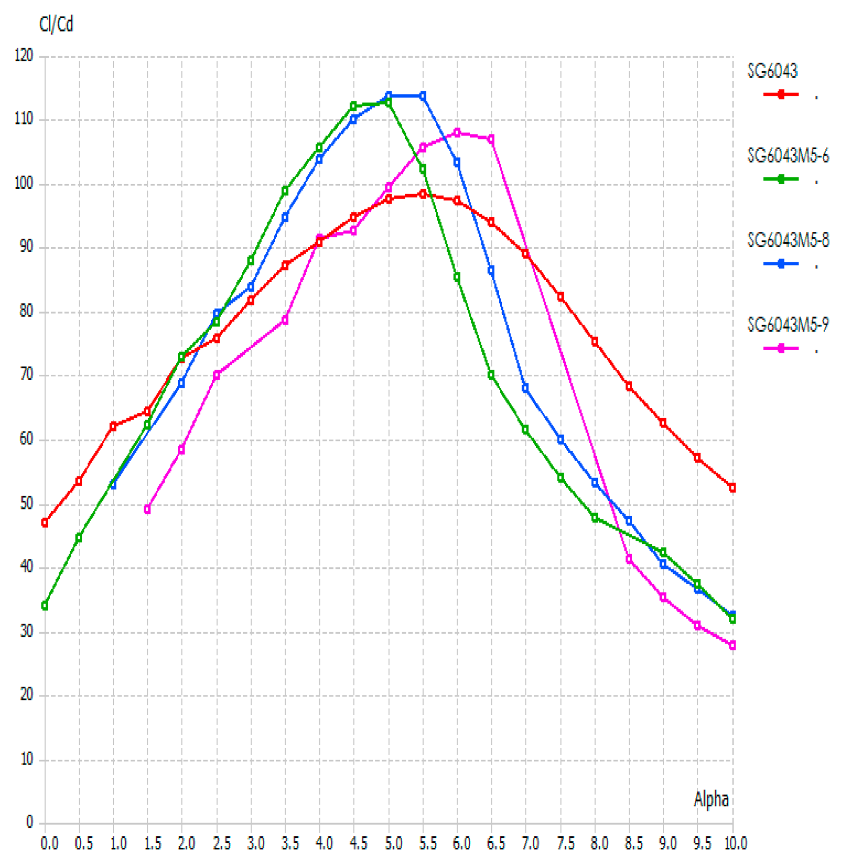
CL/CD vs. AOA of SG6043M5-6, SG6043M5-8 and SG6043M5-9 at Re. 1 × 10⁵.
Figure 15.
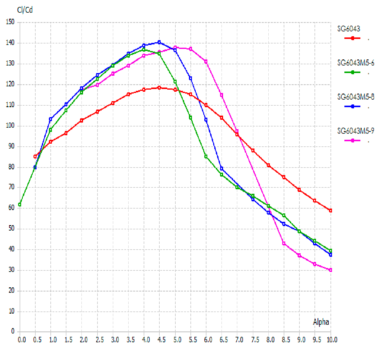
CL/CD vs. AOA of SG6043M5-6, G6043M5-8 and SG6043M5-9 at Re. 2 × 10⁵.
Figure 16.
CL/CD vs. AOA of SG6043M5-6, SG6043M5-8 and SG6043M5-9 at Re. 3 × 10⁵.
Figure 17.
CL/CD vs. AOA of SG6043M5-6, SG6043M5-8 and SG6043M5-9 at Re. 4 × 10⁵.
Figure 18.
CL/CD vs. AOA of SG6043M5-6, SG6043M5-8 and SG6043M5-9 at Re. 5 × 10⁵.
Figure 19.
CL/CD vs. AOA of SG6043M5-6, SG6043M5-8 and SG6043M5-9 at Re. 6 × 10⁵.
The airfoil SG6043M5-6, with 6% camber, performed optimally at low Reynolds numbers (1 × 10⁵ and 2 × 10⁵), achieving CL/CD values of 76.48 and 112.31. This made it suitable for applications involving very low-speed flows, such as small unmanned aerial vehicles (UAVs) or micro wind turbines.
The airfoil SG6043M5-8, with 8% camber, performs optimally at lower Reynolds numbers (3 × 10⁵, 4 × 10⁵ and 5 × 10⁵), achieving respectable CL/CD values of 140.55, 161.86 and 179.11 at AOAs of 4.5°, 4° and 3.5° respectively. This was a desirable trait, indicating improved performance with increased flow speed and reduced energy loss due to drag. Moreover, the fact that it maintained good performance over a wider Reynolds number range (3–5 × 10⁵) and a broader range of AoAs reflects its stability and robustness under varying flow conditions.
However, the airfoil SG6043M5-9, with the highest camber (9%), achieved the maximum CL/CD value of 193.44 at Re = 6 × 10⁵ and AoA = 3.5°. This indicated exceptional performance at that specific condition. Its usefulness was limited to high-Reynolds-number flows and it lacked the broader versatility observed for SG6043M5-8. The data suggest a trade-off between maximum efficiency and range of applicability. The airfoils SG6043M5-6 and SG6043M5-9 are specialized performers optimized for confined Reynolds number bands, while SG6043M5-8 offers a more balanced performance suitable for a wider operational envelope. This made SG6043M5-8 the most aerodynamically efficient and practically viable modified design for small-scale wind energy applications.
3.4. Comparison with Existing Literature
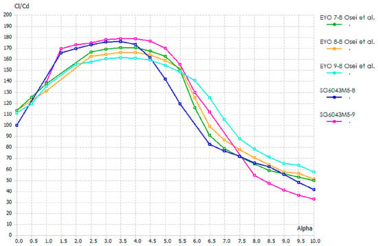
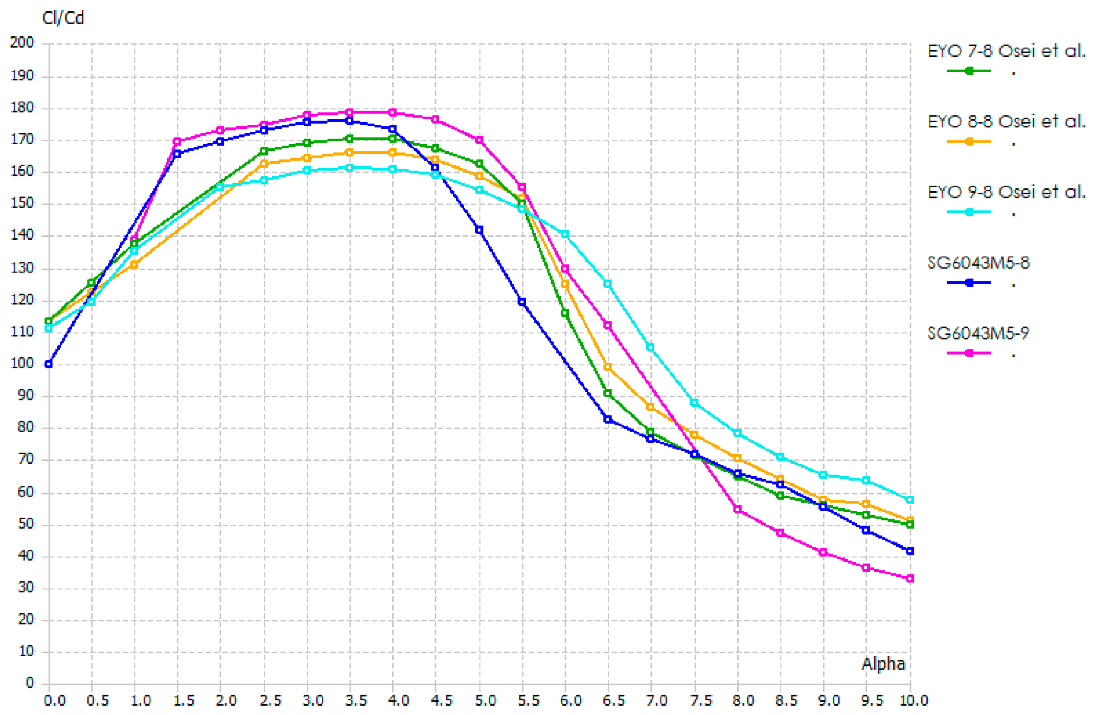
In Figure 20, compared to the existing reported modified SG6043 airfoils EYO7-8, EYO8-8, and EYO9-8, which achieved maximum lift-to-drag ratios of 169.68, 165.16, and 160.10, respectively, at a Reynolds number of 5 × 10⁵, the SG6043 variants such as SG6043M5-8 and SG6043M5-9 attained higher maximum lift-to-drag ratios of 179.11 and 178.35, respectively. This improvement indicated that the SG6043M5-8 and SG6043M5-9 not only outperformed the existing EYO-series modifications under the same Reynolds number but also exhibited enhanced optimization for minimizing drag while maximizing lift, making them more effective choices for applications requiring high aerodynamic efficiency.
Figure 20.
Comparison of modified airfoils SG6043M5-6, SG6043M5-8 and SSG6043M5-9 with EYO Series (Osei et al.) at Re. 5 × 10⁵.
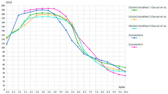
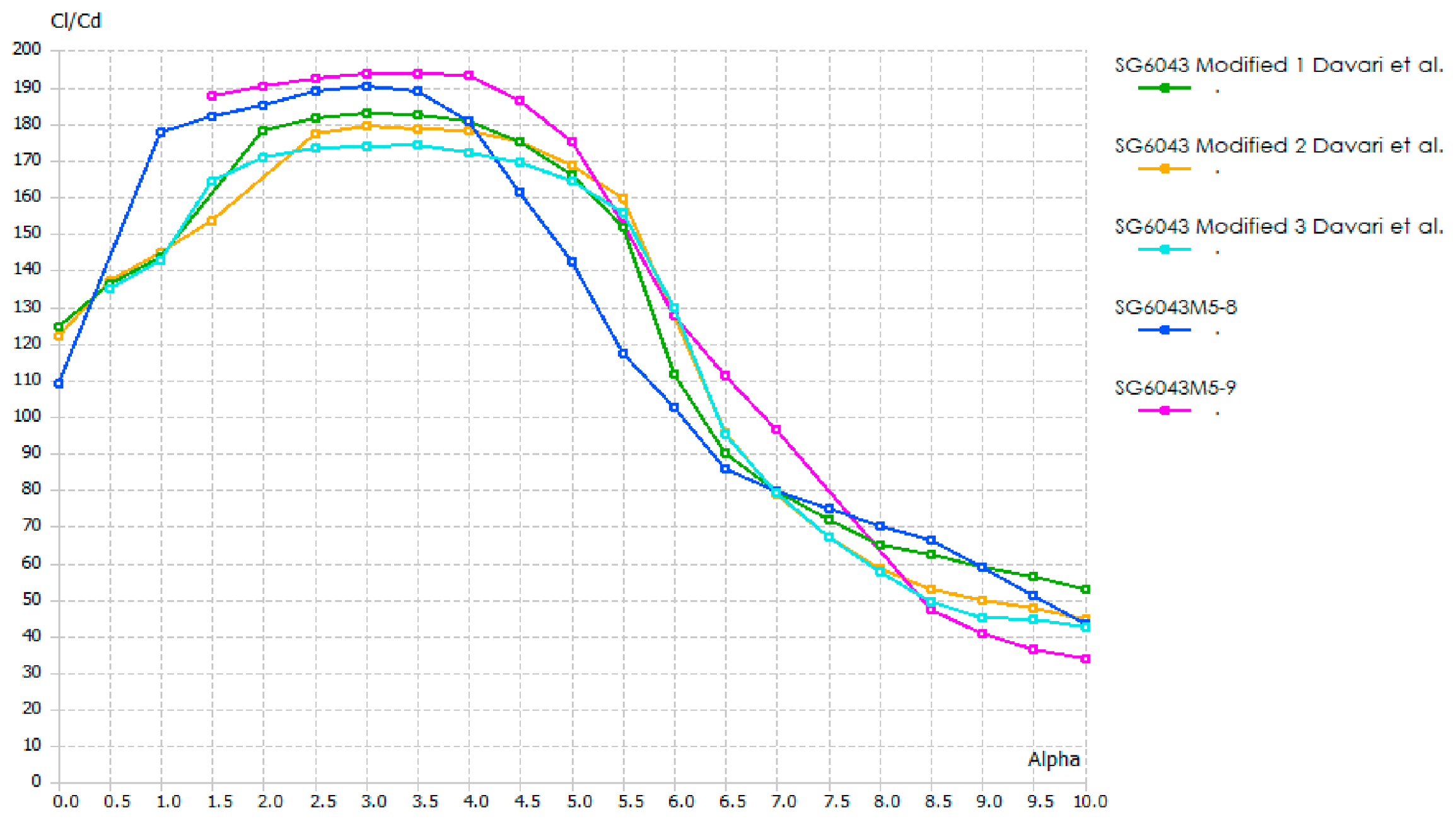
Figure 21 compared the recently reported modified SG6043 airfoils SG6043 modified 1, SG6043 modified 2, and SG6043 modified 3, which achieved maximum lift-to-drag ratios of 184.85, 182.36, and 177.25, respectively at Reynolds number of 6 × 10⁵. The SG6043 variants SG6043M5-8 and SG6043M5-9 attained higher maximum lift-to-drag ratios of 193.25 and 193.44, respectively. This represents a significant improvement over the earlier modified versions, suggesting that the SG6043M5-8 and SG6043M5-9 designs are more effective in reducing drag while maintaining or enhancing lift. Such performance highlights the aerodynamic optimization of these variants, making them particularly advantageous for high efficiency aerodynamic applications where performance at increasing Reynolds numbers is critical. The higher maximum lift-to-drag ratios achieved by SG6043M5-8 (193.25) and SG6043M5-9 (193.44) compared to previously modified variants (modified 1–3) can be attributed to improved flow attachment over the airfoil surfaces at Re = 6 × 10⁵. At this Reynolds number, inertial forces dominate, leading to thinner boundary layers and delayed flow separation. The optimized geometries of M5-8 and M5-9 maintain attached flow over a larger portion of the airfoil, reducing pressure drag while sustaining lift. Additionally, these designs delay stall to higher angles of attack, further enhancing the lift-to-drag ratio across a broader operating range, highlighting the aerodynamic efficiency of the optimized variants.
Figure 21.
Comparison of modified airfoils SG6043M5-6, SG6043M5-8 and SSG6043M5-9 with SG6043 modified 1, 2 and 3 series (Davari et al.) at Re. 6 × 10⁵.
4. Discussion
Performance improvements of the optimized SG6043 variants over the baseline SG6043 design are summarized in the table. The SG6043M5-9 variant achieved the highest CL/CD ratio of 193.44 at a Reynolds number of 6 × 10⁵, representing a 26.5% improvement over the baseline. Optimized variants also demonstrated significant improvements compared to modifications in the existing literature, surpassing computational uncertainty thresholds with 95% confidence. These results confirm the statistical significance of the performance gains and reflect robustness across Reynolds number ranges from low to high. The lift-to-drag ratio (Cl/Cd) is a widely used metric in aerodynamic performance analysis because it quantifies the efficiency of an airfoil. A higher Cl/Cd value indicates that the airfoil generates more lift for a given amount of drag, which is particularly important for wind turbine blades, low-Reynolds-number applications, or any situation where maximizing aerodynamic efficiency is critical. By using Cl/Cd, the study focuses on selecting airfoil designs that can produce the most useful lift while minimizing energy losses due to drag, directly impacting overall turbine performance and efficiency.
Additionally, Table 4 provides a comparison of the performance improvements of the optimized SG6043 variants relative to the existing literature. The SG6043M5-8 and SG6043M5-9 variants exhibited improvements of 4.5% and 4.6% over Davari et al.’s SG6043 modified 1, and improvements of 5.4% and 5.6% over Osei et al.’s EYO Series, all with associated confidence intervals that surpass computational uncertainty. Furthermore, comparisons with the literature benchmarks (Davari et al., Osei et al.) show consistent improvements beyond computational uncertainty thresholds. This confirms that the observed gains are statistically significant, robust, and not a result of simulation artifacts. The inclusion of 95% confidence intervals provides additional validation of the reliability of these improvements. The optimized variants deliver measurable and statistically verified aerodynamic advantages, validating the optimization methodology and supporting their application in small-scale horizontal axis wind turbines.
Table 4.
Performance improvements of optimized SG6043 variants compared to the baseline.
In addition to the aerodynamic performance improvement, the flow behavior around the base and optimized airfoils was analyzed to understand the underlying physical mechanisms. The baseline SG6043 airfoil exhibited early boundary layer separation near the trailing edge at higher angles of attack, which contributed to increased drag and limited aerodynamic efficiency. In contrast, the optimized airfoils (SG6043M5-6, SG6043M5-8, and SG6043M5-9) demonstrated improved flow attachment over a larger portion of the chord length.
The increase in camber enhances the suction pressure on the upper surface, resulting in higher lift generation. Additionally, the optimized geometries promote smoother streamlines and delay flow separation, particularly in SG6043M5-8 and SG6043M5-9, which leads to reduced wake region and lower pressure drag. At higher Reynolds numbers, the boundary layer remains more stable and attached, further improving aerodynamic efficiency.
Among the optimized variants, SG6043M5-8 exhibits a balanced flow structure with delayed separation and stable pressure recovery over a wide range of Reynolds numbers, while SG6043M5-9 shows maximum lift enhancement due to stronger suction effects but with slightly reduced operational range. These flow characteristics explain the observed increase in lift-to-drag ratio and confirm that the performance improvements are primarily due to delayed separation, improved pressure distribution, and reduced aerodynamic losses.
A parameter sensitivity analysis was inherently conducted through systematic variation in Reynolds number, angle of attack, and camber, as shown in Figure 6, Figure 7, Figure 8, Figure 9, Figure 10 and Figure 11 and Table 1, Table 2 and Table 3. The results demonstrate strong sensitivity of aerodynamic performance to these parameters.
The uncertainty in the numerical results was estimated using the 95% confidence intervals reported in Table 4 and Table 5, and was found to be approximately ±2%, indicating reliable and consistent simulation outcomes.
Table 5.
Comparison of CL/CD improvements for optimized SG6043 variants relative to literature benchmarks.
Furthermore, the close agreement between XFOIL and QBlade results (Table 2) confirms numerical stability and consistency of the computational approach.
5. Conclusions
Based on the literature review, the low-Reynolds-number high-performance SG6043 airfoil were selected from 30 airfoils. Before modifications, the reported performance of SG6043 was verified.
About 25 modifications were conducted to achieve an optimized design. These modifications were based on variations in thickness-to-camber ratio, angle of attack (AOA), and Reynolds number.
Among all the modified airfoils, SG6043M5-6 at Reynolds numbers of 1 × 10⁵ and 2 × 10⁵, SG6043M5-8 at Reynolds numbers from 3 × 10⁵ to 5 × 10⁵, and SG6043M5-9 at a Reynolds number of 6 × 10⁵, exhibited the best aerodynamic performance.
Notably, SG6043M5-8 and SG6043M5-9 achieved the highest lift-to-drag (CL/CD) ratios among all the modifications.
The airfoils SG6043M5-6, SG6043M5-8 and SG6043M5-9 achieved maximum CL/CD ratios, outperforming the original SG6043.
The SG6043M5-9 achieved the highest CL/CD ratio of 193.44 at a Reynolds number of 6 × 10⁵. Peak performance was observed at angles of attack ranging from 3° to 3.5°.
Compared to SG6043M5-6 and SG6043M5-9, SG6043M5-8 gives the best result over a larger AOA° range.
Future Work
This study provide valuable insights into the optimization of the SG6043 airfoil; however, several areas warrant further investigation to ensure comprehensive validation and wider applicability. Experimental validation remained essential, including wind-tunnel testing of optimized airfoil variants to verify computational predictions, as well as full-scale blade testing to evaluate performance under real-world operating conditions. Long-term durability assessments may also be undertaken under varying atmospheric conditions to establish structural reliability and operational lifespan.
On the optimization front, future research should employ advanced multi-objective optimization frameworks that simultaneously account for aerodynamic, structural, and manufacturing constraints. Integration with holistic blade design optimization methods could further enhance overall turbine performance. Moreover, unsteady aerodynamic phenomena and dynamic performance should be investigated to better capture complex, real-world operating scenarios.
Extended applications represented another important direction. The optimized airfoils should be evaluated for potential use in other low-Reynolds-number environments, such as unmanned aerial vehicles (UAVs) and marine turbines. Their performance under off-design conditions and in varying atmospheric turbulence should be examined to assess operational robustness. Finally, exploration of adaptive or morphing airfoil concepts for variable wind conditions could promote higher efficiency and flexibility in renewable energy systems.
In future work, the study should be extended to include a full 3D aerodynamic design and analysis, as the current 2D simulations provide limited insights into real-world performance. A 3D approach will enable more accurate predictions of lift, drag, and overall airfoil behavior under realistic operating conditions.
Author Contributions
Validation, M.R.L.; Formal analysis, A.L.M.; Investigation, A.A.R.; Data curation, S.M.G.; Writing—review and editing, S.B. All authors have read and agreed to the published version of the manuscript.
Funding
This research was supported by the Higher Education Commission (HEC) of Pakistan under the Indigenous PhD Fellowship Programme for 5000 Scholars (Phase-II), awarded to Arif Ali Rind (PIN: 520-162196-2EG6-73). The authors gratefully acknowledge the financial support provided by HEC.
Institutional Review Board Statement
Not applicable.
Informed Consent Statement
Not applicable.
Data Availability Statement
The data supporting the findings of this study are available from the corresponding author upon reasonable request.
Acknowledgments
The authors are grateful to Gordhan Das Valasai, Department of Environment Engineering, Quaid-e-Awam University of Engineering, Science and Technology (QUEST), Nawabshah, Pakistan, for his valuable guidance and technical input during the preparation of this manuscript.
Conflicts of Interest
The authors declare no conflicts of interest.
References
- Betz, A. Introduction to the Theory of Flow Machines; Pergamon Press: Oxford, UK, 1966. [Google Scholar]
- Miley, S.J. A Catalog of Low Reynolds Number Airfoil Data for Wind Turbine Applications; Report No. RFP-3387, UC-60; Rockwell International, Rocky Flats Plant: Golden, CO, USA, 1982. [Google Scholar]
- Drela, M. XFOIL: An Analysis and Design System for Low Reynolds Number Airfoils. Available online: http://web.mit.edu/drela/Public/papers/xfoil_sv.pdf (accessed on 12 January 2022).
- Rasheed, M.A.; Al-Qaisy, A.A. Experimental Investigation of Aerodynamic Characteristics of NACA 23015 Under Different Angles of Attack. Eng. Technol. J. 2008, 27, 2. [Google Scholar]
- Giguère, P.; Selig, M.S. New Airfoils for Small Horizontal Axis Wind Turbines. J. Sol. Energy Eng. 1998, 120, 108–114. [Google Scholar] [CrossRef] [Scilit]
- Giguère, P.; Selig, M.S. Low Reynolds Number Airfoils for Small Horizontal Axis Wind Turbines. Wind Eng. 1997, 21, 367–380. [Google Scholar]
- Hossain, S.; Raiyan, M.F.; Akanda, M.N.U.; Jony, N.H. A Comparative Flow Analysis of NACA 6409 and NACA 4412 Aerofoil. Int. J. Res. Eng. Technol. 2014, 3, 342–350. [Google Scholar] [CrossRef] [Scilit]
- Suresh, A.; Rajakumar, S. Design of Small Horizontal Axis Wind Turbine for Low Wind Speed Rural Applications. Mater. Today Proc. 2020, 23, 16–22. [Google Scholar] [CrossRef] [Scilit]
- Selig, M.S.; McGranahan, B.D. Wind Tunnel Aerodynamic Tests of Six Airfoils for Use on Small Wind Turbines. J. Sol. Energy Eng. 2004, 126, 986–1001. [Google Scholar] [CrossRef] [Scilit]
- Prakash, N.; Noronha, M.; Krishna, M. Design and Analysis of Micro Horizontal Axis Wind Turbine Using MATLAB and QBlade. Int. J. Adv. Sci. Technol. 2020, 29, 8877–8885. [Google Scholar]
- Shah, H.; Bhattarai, N.; Mathew, S.; Lim, C. Low Reynolds Number Airfoil for Small Horizontal Axis Wind Turbine Blades. In Proceedings of the Sustainable Future Energy 2012 and 10th SEE FORUM, Gadong, Brunei, 21–23 November 2012. [Google Scholar] [CrossRef] [Scilit]
- Singh, R.K.; Ahmed, M.R. Blade Design and Performance Testing of a Small Wind Turbine Rotor for Low Wind Speed Applications. Renew. Energy 2013, 50, 812–819. [Google Scholar] [CrossRef] [Scilit]
- Wata, J.; Faizal, M.; Talu, B.; Vanawalu, L.; Sotia, P.; Ahmed, M.R. Studies on a Low Reynolds Number Airfoil for Small Wind Turbine Applications. Sci. China Technol. Sci. 2011, 54, 1684–1688. [Google Scholar] [CrossRef] [Scilit]
- Yao, J.; Yuan, W.; Jianliang, W.; Xie, J.; Haipeng, Z.; Mingjun, P. Numerical Simulation of Aerodynamic Performance for Two-Dimensional Wind Turbine Airfoils. Procedia Eng. 2012, 31, 80–86. [Google Scholar] [CrossRef] [Scilit]
- Khalil, Y.; Tenghiri, L.; Abdi, F.; Bentamy, A. Improvement of Aerodynamic Performance of a Small Wind Turbine. Wind Eng. 2020, 44, 21–32. [Google Scholar] [CrossRef] [Scilit]
- Stavros, N.; Leloudas, A.; Eskantar, N.; Georgios, L.; Lygidakis, K.; Ioannis, N.; Nikolos, P. Low Reynolds Airfoil Family for Small Horizontal Axis Wind Turbines Based on RG15 Airfoil. SN Appl. Sci. 2020, 2, 452. [Google Scholar] [CrossRef] [Scilit]
- Henriques, J.C.C.; Marques da Silva, F.; Estanqueiro, A.I.; Gato, L.M.C. Design of a New Urban Wind Turbine Airfoil Using a Pressure-Load Inverse Method. Renew. Energy 2009, 34, 2728–2734. [Google Scholar] [CrossRef] [Scilit]
- Limin, Q.; Wei, S.; Gu, R.; Quan, X.; Yang, Y. The Investigation of the Airfoil for the Small Wind Turbine Based on the Seagull Airfoil. In Proceedings of the 2011 Asia-Pacific Power and Energy Engineering Conference, Wuhan, China, 25–28 March 2011. [Google Scholar]
- Shah, H.; Mathew, S.; Lim, C.M. A Novel Low Reynolds Number Airfoil Design for Small Horizontal Axis Wind Turbines. Wind Eng. 2014, 38, 377–391. [Google Scholar] [CrossRef] [Scilit]
- Singh, R.K.; Ahmed, M.R.; Zullah, M.A.; Lee, Y.-H. Design of a Low Reynolds Number Airfoil for Small Horizontal Axis Wind Turbines. Renew. Energy 2012, 42, 66–76. [Google Scholar] [CrossRef] [Scilit]
- Wang, Y.; Shen, S.; Li, G.; Huang, D.; Zheng, Z. Investigation on Aerodynamic Performance of Vertical Axis Wind Turbine with Different Series Airfoil Shapes. Renew. Energy 2018, 126, 801–818. [Google Scholar] [CrossRef] [Scilit]
- Castelli, M.R.; Englaro, A.; Benini, E. The Darrieus Wind Turbine: Proposal for a New Performance Prediction Model Based on CFD. Energy 2011, 36, 4919–4934. [Google Scholar] [CrossRef] [Scilit]
- Kevadiya, M.; Vaidya, H.A. 2D Analysis of NACA 4412 Airfoil. Int. J. Innov. Res. Sci. Eng. Technol. 2013, 2, 1686–1691. [Google Scholar]
- Wang, J.; Sheng, J.; Shi, L.; Zou, F. Analysis of Aerodynamic Performance of Wind Turbine Airfoil Under the Same Relative Thickness. Water Resour. Power 2011, 29, 142–144. [Google Scholar]
- Jha, S.; Gautam, U.; Narayanan, S.; Kumaraswami Dhas, L.A. Effect of Reynolds Number on the Aerodynamic Performance of NACA0012 Aerofoil. IOP Conf. Ser. Mater. Sci. Eng. 2018, 377, 012129. [Google Scholar] [CrossRef] [Scilit]
- Alaskari, M.; Abdullah, O.; Majeed, M.H. Analysis of Wind Turbine Using QBlade Software. IOP Conf. Ser. Mater. Sci. Eng. 2019, 518, 032020. [Google Scholar] [CrossRef] [Scilit]
- Yang, S.L.; Chang, Y.L.; Arici, O. Navier–Stokes Computations of the NREL Airfoil Using a k–ω Turbulent Model at High Angles of Attack. J. Sol. Energy Eng. 1995, 117, 304–310. [Google Scholar] [CrossRef] [Scilit]
- Roy, S.; Das, B.; Biswas, A. Influence of Camber Ratio and Thickness Ratio on the Airfoil Performance. In Recent Advances in Mechanical Engineering; Lecture Notes in Mechanical Engineering; Springer: Singapore, 2021. [Google Scholar]
- Osei, E.Y.; Opoku, R.; Sunnu, A.K.; Adaramola, M.S. Development of High Performance Airfoils for Application in Small Wind-Turbine Power Generation. Adv. Mater. Sci. 2020, 2020, 9710189. [Google Scholar] [CrossRef] [Scilit]
- Davari, H.S.; Davari, M.S.; Botez, R.M.; Chowdhury, H. Maximizing the Peak Lift-to-Drag Coefficient Ratio of Airfoils by Optimizing the Ratio of Thickness to the Camber. Sustain. Earth Rev. 2023, 3, 46–61. [Google Scholar]
- Alsahlani, A.A.; Al-Saad, M.; Al-Mosallam, M. A Study of Impacts of Airfoil Geometry on the Aerodynamic Performance at Low Reynolds Number. Int. J. Mech. Eng. Robot. Res. 2023, 12, 2. [Google Scholar] [CrossRef] [Scilit]
- Osei, E.Y.; Opoku, R.; Sunnu, A.K.; Adaramola, M.S.; Kyeremeh, E.A. Aerodynamic Performance Characteristics of Three New EYO-Series Low Reynolds Number Airfoils for Small Wind Turbine Blades. Alex. Eng. J. 2022, 61, 12301–12310. [Google Scholar] [CrossRef] [Scilit]
- Davari, S.; Jamalabadi, M.Y.A.; Davari, M.S. Optimizing the SG6043 Airfoil for Small Wind Turbines at Low Reynolds Numbers Using XFOIL. Mech. Eng. Adv. 2025, 3, 2486. [Google Scholar] [CrossRef] [Scilit]

Disclaimer/Publisher’s Note: The statements, opinions and data contained in all publications are solely those of the individual author(s) and contributor(s) and not of MDPI and/or the editor(s). MDPI and/or the editor(s) disclaim responsibility for any injury to people or property resulting from any ideas, methods, instructions or products referred to in the content. |
© 2026 by the authors. Licensee MDPI, Basel, Switzerland. This article is an open access article distributed under the terms and conditions of the Creative Commons Attribution (CC BY) license.