Entry

Masonry Arches: Thrust Line and Strength

by
Danila Aita
Department of Civil and Environmental Engineering, Politecnico di Milano, 20133 Milan, Italy
Encyclopedia 2026, 6(3), 57; https://doi.org/10.3390/encyclopedia6030057
Submission received: 13 November 2025 / Revised: 30 January 2026 / Accepted: 24 February 2026 / Published: 6 March 2026
(This article belongs to the Collection Encyclopedia of Engineering)

Definition

The concept of ‘thrust line’ has its roots in historical contributions that laid the foundation for the development of modern tools useful for the limit analysis of masonry arches and vaults. This concept can be traced back to two different, but related, notions: ‘line of resistance’ and ‘line of pressure’. In this paper, both historical contributions and recent developments of the thrust line method will be discussed with a focus on those formulations which take into account the material’s properties, in particular compressive strength.

1. Introduction

This paper aims to examine the historical roots of the thrust line concept, developed in the context of 19th-century studies on the static analysis of masonry arches, focusing on those contributions capable of taking into account the masonry strength, placing them as a basis for possible modern developments.

1.1. Limit Analysis of Masonry Structures

To better understand how this topic can be framed from a theoretical point of view, it may be necessary to first review the approaches related to the structural analysis of unreinforced masonry structures, a crucial problem in contemporary structural mechanics due to the complex mechanical behaviour of masonry, a heterogeneous material with low tensile strength and good compressive strength [1,2,3,4].
As is well known, different approaches are used to address this matter. In the recent scientific literature, discrete element (DEM) [5,6,7] and finite element methods (FEM) are available as powerful tools to capture the mechanical response of a masonry structure under gravitational or seismic loads by taking into account the blocks arrangement, the material properties, the features of the interfaces, and the presence of reinforcements, sometimes with reference to specific case studies or to interpret experimental tests [8,9,10]. For a comprehensive discussion of modelling strategies for masonry characterization and analysis of unreinforced masonry structures, the interested reader is referred to [11,12,13].
However, as observed among others by [12], when modelling the structural behaviour of masonry using refined formulations, several mechanical parameters must be considered, sometimes affected by uncertainties or difficult to determine. Furthermore, these methods can be computationally demanding. For this reason, simple approaches based on the static and kinematic theorem of limit analysis are still considered valuable in engineering practice today for rapidly assessing masonry structures, providing useful information for conservation purposes [14]. The objective of classical limit analysis is to assess structural safety and/or determine the maximum load-bearing capacity of a structure. Starting from the fundamental contribution by Kooharian [15], Jacques Heyman [16,17,18] transferred the philosophy of plastic theory from the steel to the stone skeleton, studying the mechanics of masonry structures in the theoretical background of limit analysis. Re-evaluating pre-elastic contributions [19], he assumed simplifying hypotheses on the masonry material (zero tensile strength, infinite compressive strength, no sliding between the blocks). Considering these assumptions, ref. [20] offers an overview of the theoretical aspects of limit analysis applied to masonry structures, in particular arches, vaults, and domes. Heyman’s no-tension model has been widely and successfully used to examine the stability of masonry systems by exploiting both the static and kinematic theorems of limit analysis: on the one hand, his well-known safe theorem made it possible to re-evaluate the idea of thrust line and to leverage graphical statics to assess the equilibrium of masonry arches and vaults using both classical [21,22] and computational approaches [23,24]; on the other, kinematic analysis was applicable to examine possible collapse modes of both vaulted structures and masonry buildings under gravitational or seismic loads [25,26,27,28].
Although Heyman limit analysis [16,17,18] has proven to be a reliable technique for the structural analysis of masonry structures, a number of scholars (see, for example [29]) observe that such a simplified approach does not take into account important factors that should be considered to avoid overestimating the load-bearing capacity of an unreinforced masonry structure, such as the possibility of sliding between the masonry blocks, and masonry crushing.
Given the complexity of the theoretical background of studies on the structural response of masonry structures, only briefly outlined above, and observing that limit analysis plays a crucial role, this paper seeks to draw the readers’ attention to an important topic: the relationship between the thrust line method, framed in the static theorem of limit analysis, and the introduction of material strength in the structural analysis of masonry arches.
The subject offers the opportunity to explore the intriguing historical context in which the concept of thrust line emerged, between limit analysis and elastic analysis, a framework with theoretical inconsistencies, as will be described in Section 1.2. Considering a limited compressive strength allows one to overcome the simplifications due to the classical Heyman’s approach, which reduce the analysis of masonry arch structures to an essentially geometric problem [21]. Although it is recognized that taking into account material characteristics, like strength, is not always necessary to evaluate a masonry structure’s stability [21,24], it can be significant when it comes to conservation aspects, such as damage [30,31,32] and reinforcement techniques [33]. The influence of a limited strength on the structural response of masonry arches and bridges is also confirmed by experimental investigations, as described by [31]. Considering strength is essential to examine the effects of material properties on the collapse behaviour of masonry structures [32,34] and to perform rigorous structural assessment of large masonry vaults or domes; see, for example, the large-scale masonry arch bridge studied by [35] and the Global Vipassana Pagoda in Mumbai [36,37].
Investigating the relationship between thrust line and compressive strength offers the opportunity to critically examine the so-called Méry method, which is still widely used in engineering practice, highlighting the current misinterpretation of the original approach proposed by the author [38].
Finally, state-of-the-art reviews on the main historical contributions based on the thrust line approach [39,40] focus on the equilibrium conditions and mathematical developments of the method, while an analysis on the relationship between thrust line and strength in a historical perspective is missing. This paper aims to contribute in this direction.

1.2. Historical Context in Which the Thrust Line Method for Masonry Arches Was Developed: A Focus on Compressive Strength

As is well known [39,40,41,42], the thrust line method starts from pre-elastic theories on masonry arches, which model masonry arches as assemblies of rigid blocks with unilateral constraints at the interfaces, by implicitly assuming zero tensile strength and infinite compressive strength, with the possibility of easily considering the presence of finite cohesion or finite friction [19,38,43,44]. Capturing the effects of material strength using the thrust line method is more complex.
Before delving into a detailed analysis of the topic, it is recalled that in the historical literature on pre-elastic theories of arch structures, two important lines of research can be identified: the kinematic approach, grounded in the contributions of de la Hire [45] and Mascheroni [46], and the static approach, within which the concept of pressure curve develops. The well-known method of maximis and minimis, proposed by Coulomb [19], can be regarded as the foundation of the structural assessment of masonry arches according to a ‘static’ approach. Coulomb considers a symmetric arch subjected to symmetric load conditions, Figure 1a. For symmetry, only one half of the arch can be studied. At the crown section aG acts an eccentric horizontal thrust, f, whose position is defined by point f. To focus on ‘rotational’ equilibrium, a simplified version of Coulomb’s approach is briefly reviewed, by assuming unlimited compressive strength, zero tensile strength, infinite friction, and infinite cohesion between the voussoirs. The equilibrium of the arch’s portion between the crown section aG and any joint Mm (Figure 1a) is respected if the internal force at joint Mm passes through a point internal to the joint itself. For each position f of the crown thrust, f, the limit condition related to the single joint corresponds to the reaction passing through joint’s end points, M or m. Equilibrium relations allow for determining a minimum and a maximum value for f, depending on whether the resultant reaction at joint Mm passes through point M ( f m i n ) or m f m a x . By repeating this procedure for any joint Mm, the arch is safe if a range exists for the values of the thrust, i.e., if max f m i n ≤ min f m a x .
Coulomb’s method served as the basis for the introduction of the graphical method of thrust line, declined through the concepts of ‘line of pressure’ and ‘line of resistance’ [44], which were later widely employed by scholars examining the mechanical behaviour of masonry arches. According to [38,43,44], the ‘line of resistance’ is defined as the polygon whose vertexes are the centres of pressures of the internal compressive forces at adjacent joints; the ‘line of pressure’ is related to the funicular polygon corresponding to the masonry arch and is defined as the envelope of the lines of actions of the compressive internal forces acting on adjacent joints (see Figure 1b).
Examining the past scientific literature, studies based on the notion of thrust line that consider the compressive strength of masonry have developed in a very interesting context that is worth exploring to understand the theoretical assumptions, sometimes contradictory, within which they are framed.
On the one hand, thrust line method harks back to pre-elastic theories, from the Hooke’s anagram on the inverted catenary [47], corresponding to what will be called ‘line of pressure’, to the modelling of the arch as a system of rigid blocks subject to unilateral constraints [19,45] at the joints, which will lead to the idea of ‘line of resistance’. It is precisely with reference to this pre-elastic context that the thrust line notion can be modernly classified within the scope of limit analysis [16,17,18]. Starting from the formalization provided by Gerstner [43] and Moseley [44], it becomes a powerful tool to illustrate the equilibrium of the arch. With reference to the notion of ‘line of resistance’ (Figure 1b), the intersection point between the thrust line and each joint provides information on the critical joints: when the ‘line of resistance’ intersects a joint at the extreme edges (intrados or extrados), a local limit equilibrium condition is attained; from a kinematic point of view, this condition corresponds to possible mutual rotations between the voussoirs, i.e., to the formation of a plastic hinge. With reference to the concept of ‘line of pressure’, the inclination of the internal reaction provides information on the possibility of sliding, assuming a finite friction coefficient at the interfaces. In this regard, it is worth remembering that, according to modern developments in limit analysis, considering finite friction is a delicate matter, since it corresponds to a non-standard plastic behaviour [48,49,50,51]. Assuming that there is no sliding between the voussoirs, the arch is stable if it is possible to identify any thrust line passing completely inside it, as already recognized by Moseley [44] based on the Coulomb equilibrium approach [19]. This finding is crucial because it states that it is sufficient to find one of the infinitely many statically admissible thrust lines to assess the stability of the arch. Determining the ‘true’ thrust line is not required. This observation allowed Heyman [16,17,18] to re-evaluate pre-elastic approaches by framing them within the context of limit analysis through the well-known safe theorem.
On the other hand, during the historical period in which the thrust line method was conceived, the theory of linear elasticity began to be formulated. Navier [52], Cauchy [53], Poisson [54], and Lamé and Clapeyron [55] contributed to the formulation of the theory of elastic bodies and began to consider the strength of materials. The masonry arch was a strange object: it was still studied within the framework of equilibrium analysis, following the approach based on Coulomb’s method [19]; the ‘elastic’ context, however, influenced the treatment of the thrust line method, with some contradictions. Paradoxically, in the 19th century, the theoretical value of the pre-elastic static approach in which the thrust line method was developed was not acknowledged: indeed, the concern of scholars and engineers became to remove the indeterminacy of the solution, that is, to determine the ‘true’ thrust line by introducing unclear criteria, a priori or experimentally derived [56,57,58,59,60,61]. These procedures were inconsistent with the theoretical background of both limit analysis, according to which, for a stable structure, there exist infinitely many statically admissible solutions, and elastic analysis, according to which the ‘true’ thrust line cannot be determined by considering only the equilibrium equations.
Gradually, thanks to the contributions of Navier [52], Barlow [56], Crotti [62], and later, Castigliano [63,64], a theoretical path emerges whereby the ‘true’ thrust line can be found only by considering the arch as an elastic hyperstatic system, correctly applying the theory of elasticity, appropriately adapted to also consider the stress–strain relationship for the masonry material and the constraint kinematic conditions at the arch’s springing. The interested reader is referred to previous reviews on this topic [41,42,65,66,67,68,69].
The context in which limited compressive strength is introduced into the thrust line method is therefore complex, straddling limit analysis and elastic analysis. In historical contributions, the same theoretical inconsistencies that emerged regarding the determination of the ‘true’ thrust line are also found in the definition of the flexural capacity of arch cross-sections when considering strength, since the limit distribution of stresses along the cross-section’s depth is assumed to be linear. Here, too, elastic analysis influences the thrust line method, which instead would fall within the scope of limit analysis.
In this ‘elastic’ perspective, two main approaches are followed. The first, also known as the ‘middle third’ method, devised by Navier himself [52,68], considers zero tensile strength and infinite compressive strength; furthermore, any cross-section is supposed to be entirely compressed. The ‘limit’ condition is attained when the distribution of the stresses along the joint’s depth is triangular, with a nil value of the stress at the intrados or extrados point of the joint (the section is not partialized). The second approach instead considers a limit value for the compressive strength of masonry: the maximum compressive stress is reached at the joint’s extrados or intrados, and its magnitude must not exceed the limit value, σ c . This value could coincide with the compressive strength of masonry or be interpreted as a permissible stress, in agreement with the elastic theory.
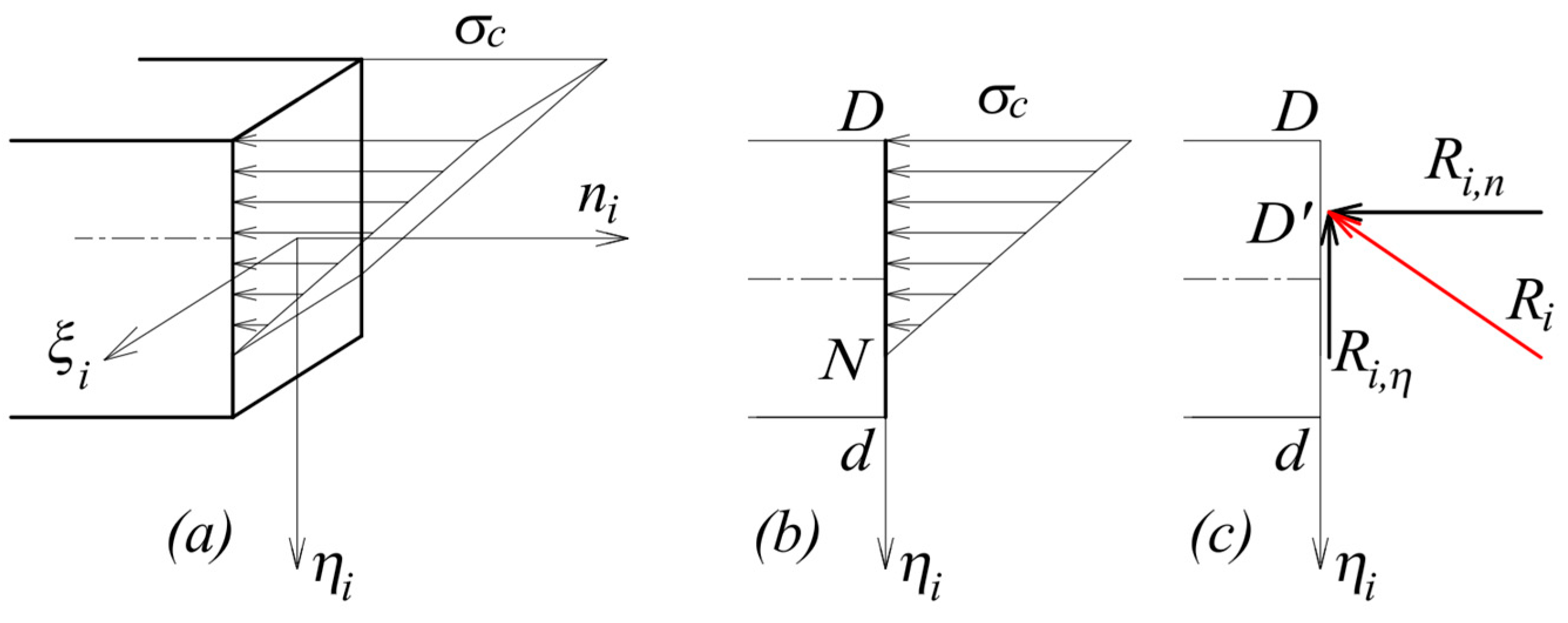
Starting from these ‘elastic’ assumptions, in the second part of his memoir [38], Méry exploits the concept of ‘line of resistance’ to impose a limit on the compressive strength of masonry. Méry refers to a linear distribution of the stresses along the joint’s depth, according to the linear elastic theory; assuming that the tensile strength is nil, he admits that the section partializes, as shown in Figure 2a,b.
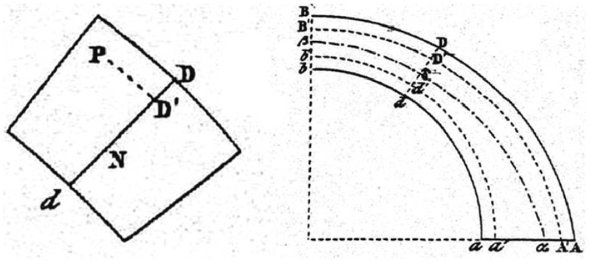
The analysis is conducted by considering a generic thrust line lying inside the thickness of the arch; see, for example, the curve β δ α in Figure 3, right, drawn from the original [38]. Let assume that, at any joint i, indicated by Méry as joint dD, such thrust line passes through point D′; see Figure 2c and Figure 3 left. The minimum distance of the centre of pressure from the end D, i.e., the segment D′D, is determined by considering the resultant reaction at any joint i, R i , of components R i , n and R i , η , normal and tangent to the joint dD, respectively (Figure 2c). Given the linear distribution of the normal stresses, N D = 3   D D ’ ; the reaction, R i (and then, the thrust line under examination) is compatible with σ c if:
D D ’ ≥ 2 3   R i , n σ c .
A further possible interpretation of Méry’s approach is to consider the reaction R i corresponding to the most ‘critical’ cross-section, and to then apply the distance D D ’ thus determined as a limit to all cross-sections of the arch. It is important to note that the procedure proposed by Méry [38] does not coincide with the so-called ‘Méry method’, which considers the limits provided by the ‘middle third’ of the cross-section, conceptually due to Navier [52], as explained above.
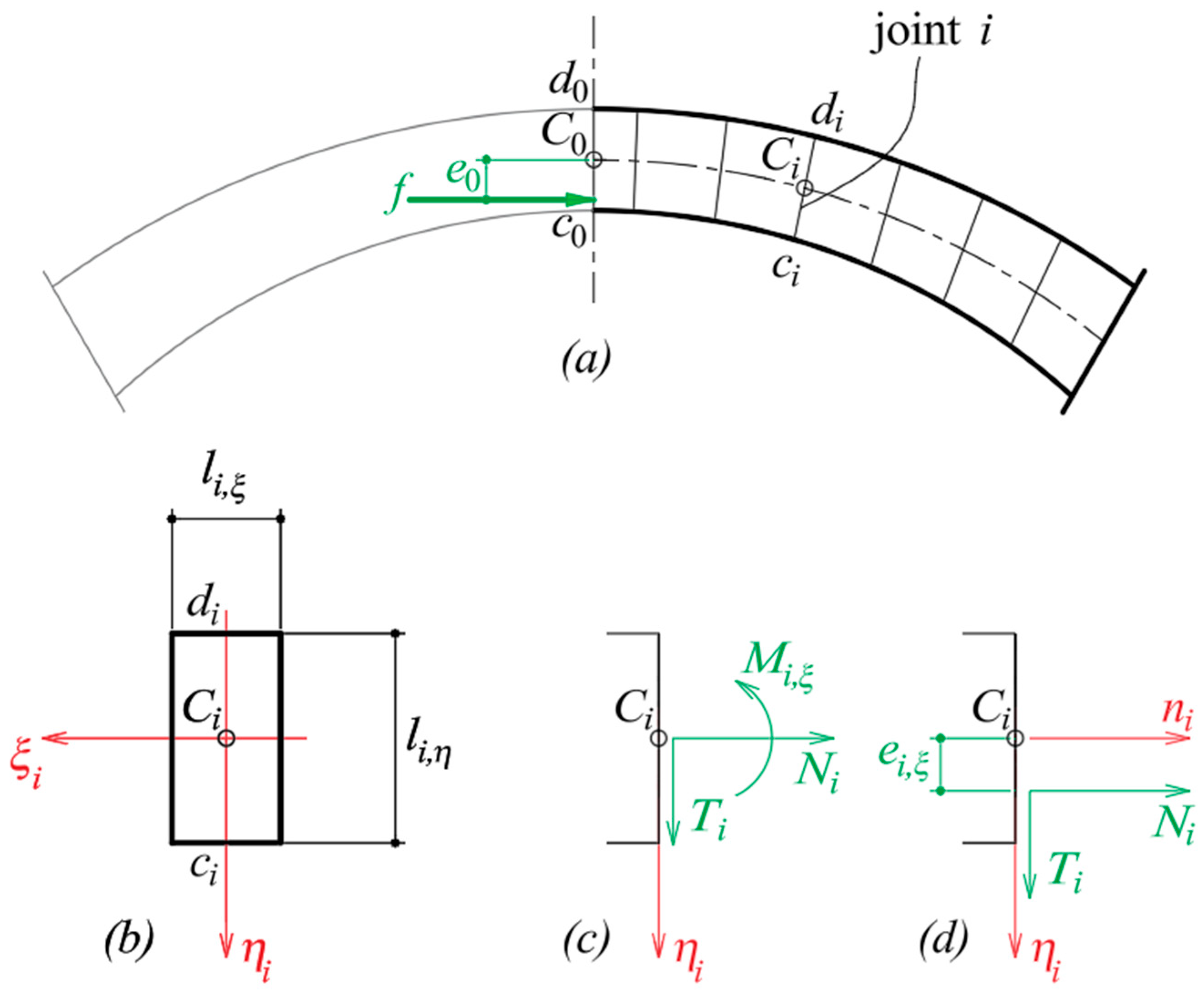
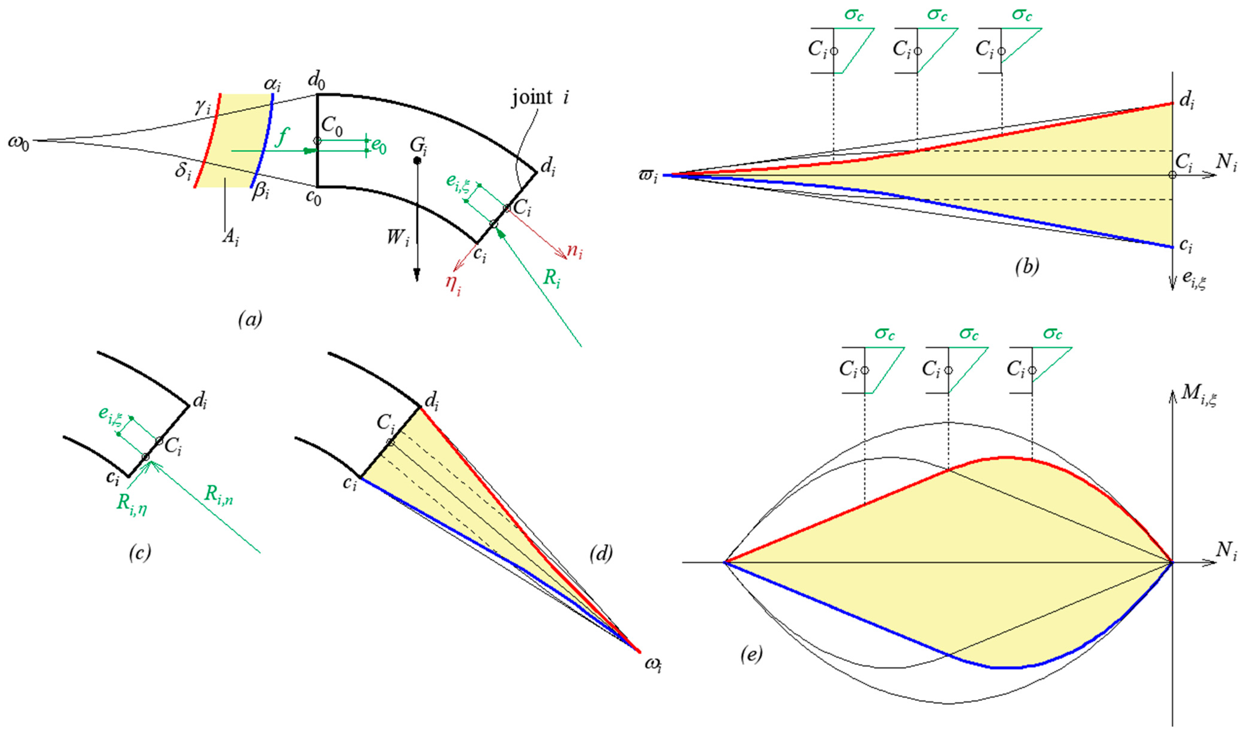
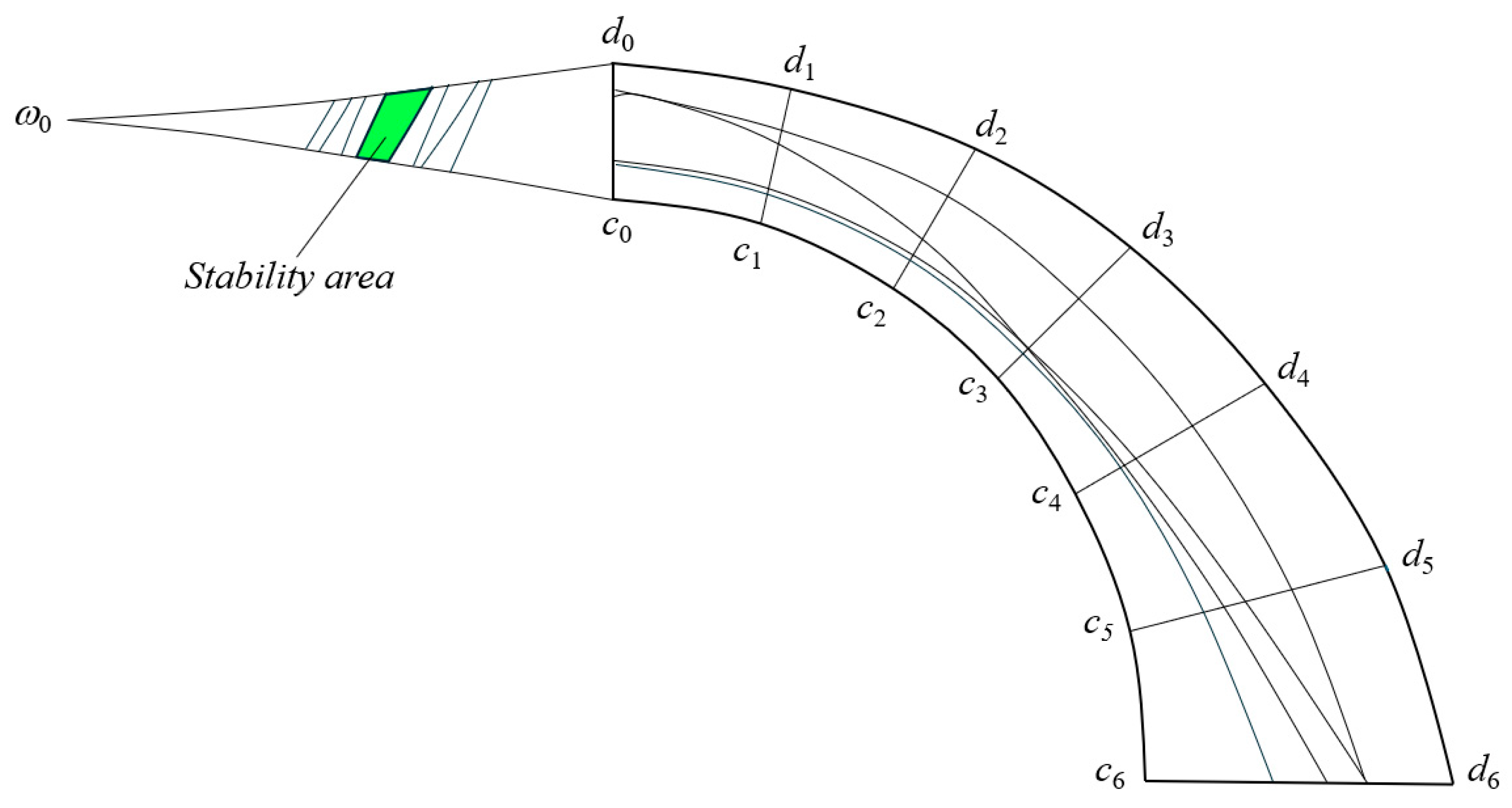
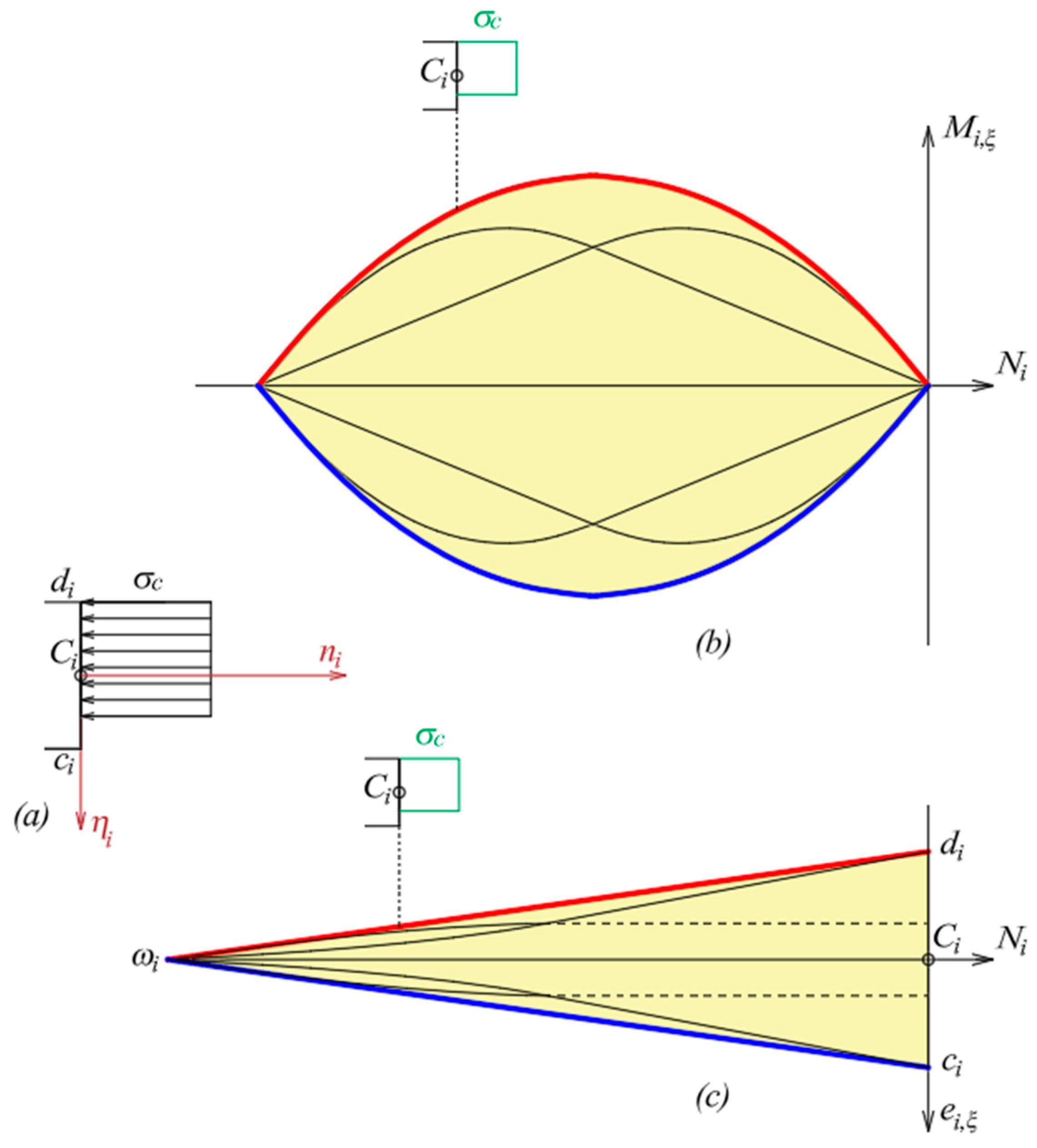
A more rigorous way to consider the limited compressive strength, even if in the contradictory theoretical context between limit analysis and elastic analysis just described, is formulated by Durand-Claye [70], who assumes the same hypotheses considered by Méry, i.e., a linear distribution of the stresses along any joint, with the possibility of partializing the cross-section due to the zero tensile strength. Given its relevance to the topic of this work and the enlightening potential inherent in the graphical representation proposed by Durand-Claye, the method is briefly illustrated below using a modern notation, in terms of stress resultants [71,72,73,74,75], keeping in mind that the original procedure relied on complex constructions of graphic statics. To the aims of the current discussion, it is sufficient to recall that this graphic method is conceived to assess the structural safety of symmetric arches loaded symmetrically. By symmetry assumption, an eccentric horizontal thrust, f, acts on the ideal vertical crown section c 0 d 0 ; its eccentricity with respect to the centroid, C 0 , of this section is denoted by e 0 (Figure 4a). The starting point is to impose equilibrium on the arch’s portion between the symmetry axis c 0 d 0   and any joint i (Figure 4a), with dimensions l i , ξ   × l i , η (Figure 4b), and to formally write the expressions for the stress resultants (normal force, N i , shear force, T i , and bending moment, M i , ξ ; see Figure 4c) as functions of the horizontal crown thrust, f, and its eccentricity, e 0 (see Figure 4a). At each joint i, the axes of inertia are denoted as ξ i and η i ; the vector n i is normal to the joint (Figure 4b–d); the internal reaction is indicated with R i (Figure 5a). Durand-Claye considers strength limitations at any joint i by assuming that the ‘limit’ (linear) stress distribution is that corresponding to the attainment of a limit magnitude for the compressive stress, σ c , at the intrados or at the extrados of the joint (see the stress distribution of Figure 2a,b). By denoting by N i the compressive (negative) normal force and by e i , ξ its eccentricity with respect to the centroid, C i , of any joint i (Figure 4d), so that M i , ξ = N i   e i , ξ , such a limit condition can be represented by the c i ϖ i and d i ϖ i curves in the N i , e i , ξ plane, coloured blue and red, respectively, in Figure 5b. All statically admissible solutions compatible with the strength requirements at any joint i are obtained by considering the equilibrium of the arch’s portion between the crown joint, c 0 d 0 , and joint i , imposing the ‘limit’ condition just described (Figure 5b) on the normal force N i as a function of the eccentricity e i , ξ . Considering the normal and tangential components of the internal reaction R i (Figure 5c), this ‘limit’ condition can be represented graphically for any joint i by the curves c i ω i and d i ω i in Figure 5d with reference to the normal component R i , n , i.e., in the R i , n , e i , ξ plane. Note that the same ‘limit’ condition can be drawn in the N i , M i , ξ plane; see the blue and red curves in Figure 5e. The corresponding stress distribution along the joint’s depth is reported (for positive bending moment) in Figure 5b,e. Using graphical statics, Durand-Claye identifies all statically admissible solutions related to the portion of arch just considered as the points f , e 0 belonging to the region A i of the f , e 0   plane, bounded by the curves α i β i and γ i δ i (Figure 5a), corresponding to the blue ( c i ω i ) and red ( d i ω i ) curves plotted in Figure 5d, respectively. The so-called ‘stability area’ A related to the entire arch is obtained by intersecting all the A i regions (including the region c 0 ω 0 d 0 of the f , e 0   plane; see Figure 5a). In Figure 6, elaborated from the original contribution [70], the stability area A has been coloured green.
The graphical procedure aims to visualize the entire set of statically admissible solutions in the f , e 0 plane, i.e., to determine all the thrust lines compatible with both equilibrium and strength. Figure 6 refers to a safe condition, since infinitely many statically admissible solutions are identified by the points f , e 0 belonging to the stability area A. When the stability area shrinks to a single point, incipient collapse occurs.
It is interesting to observe that, from the perspective of the first question raised in this complex context, i.e., the search for the ‘true’ thrust line, Durand-Claye’s contribution is rigorous, prefiguring a sort of safe theorem of limit analysis: “de la possibilité de l’équilibre, nous concluons a la stabilité” [70]: Durand-Claye does not search for the ‘true’ solution; instead, he determines whether statically admissible solutions exist. Elastic theory, however, impacts the ‘limit’ condition imposed by Durand-Claye on the bending moment at each joint when considering a limited compressive strength, resulting in a linear distribution of stresses, which is not consistent with the theoretical framework of limit analysis.

2. Modern Applications of the Thrust Line Concept

As already recalled in Section 1, in recent times, Heyman [16,17,18] rediscovered Coulomb’s approach [19] and the pre-elastic theories on masonry arches [45,46,47] by formalizing his well-known safe theorem: if sliding is not allowed (i.e., the friction coefficient is assumed to be infinite), while the compressive strength of masonry is infinite, any thrust line found within the thickness of a masonry arch or vault is considered safe. The theoretical breakthrough brought about by Heyman’s contribution has allowed the thrust line method to be rigorously framed within the scope of limit analysis, in particular the static approach, appropriately combined with the kinematic approach when it is used to identify the collapse condition.

2.1. Considering Compressive Strength in the Framework of Limit Analysis

In the historical contributions described in Section 1.2, when considering the limited compressive strength in the thrust line method, a somewhat paradoxical scenario occurs where the elastic analysis influences the stress distribution [38,70]. In modern studies based on the thrust line method, on the contrary, the focus on the resistance of materials has shifted towards limit analysis, thus expanding Heyman’s safe theorem [16,17,18]. The collapse condition is identified as any stress field in which the applied forces are just sufficient to cause failure, while the internal stresses balance the externally applied forces. The problem is divided into normal and tangential sub-problems for which limit conditions can be established to define the domain of the statically admissible solutions [76]. As regards the introduction of the compressive strength of masonry, we refer to the normal problem, which allows one to exploit the static theorem of limit analysis by assuming standard plastic behaviour [48,49,50,51,76] under the hypothesis that there is no sliding.
To clarify how this theoretical framework influences the thrust line method under the assumption of limited compressive strength, we propose a comparison between the original contribution of Durand-Claye and its modern version, based on some recent contributions [71,72,73,74,75], to illustrate the differences between the two formulations in the bending capacity of the arch joints. The object of investigation is a symmetric arch, with symmetric loading conditions (Figure 4a). Adopting a notation consistent with that of Figure 4 and limiting the description of the procedure to the normal problem, the revised version of the ‘stability area’ method assumes that the local limit condition is a rectangular distribution of the normal compressive stresses (of magnitude σ c ) along the joint’s depth, admitting joint’s partialization (rectangular stress block, see Figure 7a). This limit stress distribution implies that the magnitude of the limit bending moment, M i , ξ l i m , can be expressed as a function of the normal force, N i :
M i , ξ l i m = − N i l i , η 2 1 + N i l i , ξ   l i , η   σ c  
The attainment of the negative (resp. positive) limit bending moment (see Relation (2)) corresponds to the blue (resp. red) curve in the N i , M i , ξ plane (Figure 7b) and in the N i , e i , ξ plane (Figure 7c), with a limit stress distribution of the type shown in Figure 7a–c.
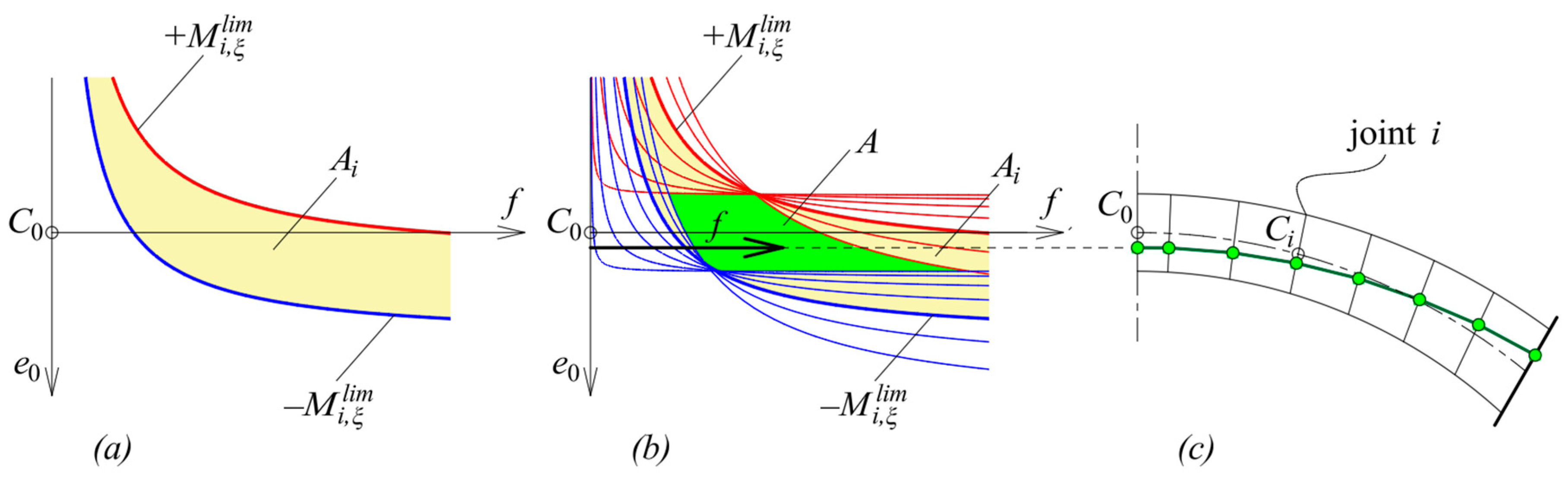
To find all statically admissible solutions, we proceed in a similar way to what was described with reference to Figure 5a. Imposing the limit conditions M i , ξ =   ∓   M i , ξ l i m at any joint i allows one to plot the corresponding limit curves in the f , e 0 plane, denoted as − M i , ξ l i m (blue) and + M i , ξ l i m (red) in Figure 8a. The region A i of the f , e 0 plane, delimited by such curves and coloured light yellow in Figure 8a,b, contains all the statically admissible solutions related to joint i, implicitly defined by the inequalities − M i , ξ l i m ≤ M i , ξ ≤ + M i , ξ l i m . By repeating the procedure for all joints i, the stability area, A (see the green region in Figure 8b), is obtained by intersecting all the regions A i .
Starting from any point of the ‘stability area’ of Figure 8b, with coordinates f , e 0 , the corresponding ‘line of resistance’ can be easily traced using graphical statics or considering the eccentricity e i , ξ = M i , ξ / N i at each joint. The interested reader is referred to [71,72,73,74,75] for further details on the applications of the method to masonry arches and, considering axial-symmetric load conditions, to domes of revolution. The method can be applied to assess the bearing capacity of masonry arches under live loads: in this case, the collapse load multiplier can be derived with the desired precision in a semi-analytical way since it allows the critical joints to be easily identified.
It is interesting to note that, while the Durand-Claye method refers to the concept of ‘line of resistance’, there are modern developments of the thrust line method that exploit the concept of ‘line of pressure’, as will be clarified in Section 2.2.
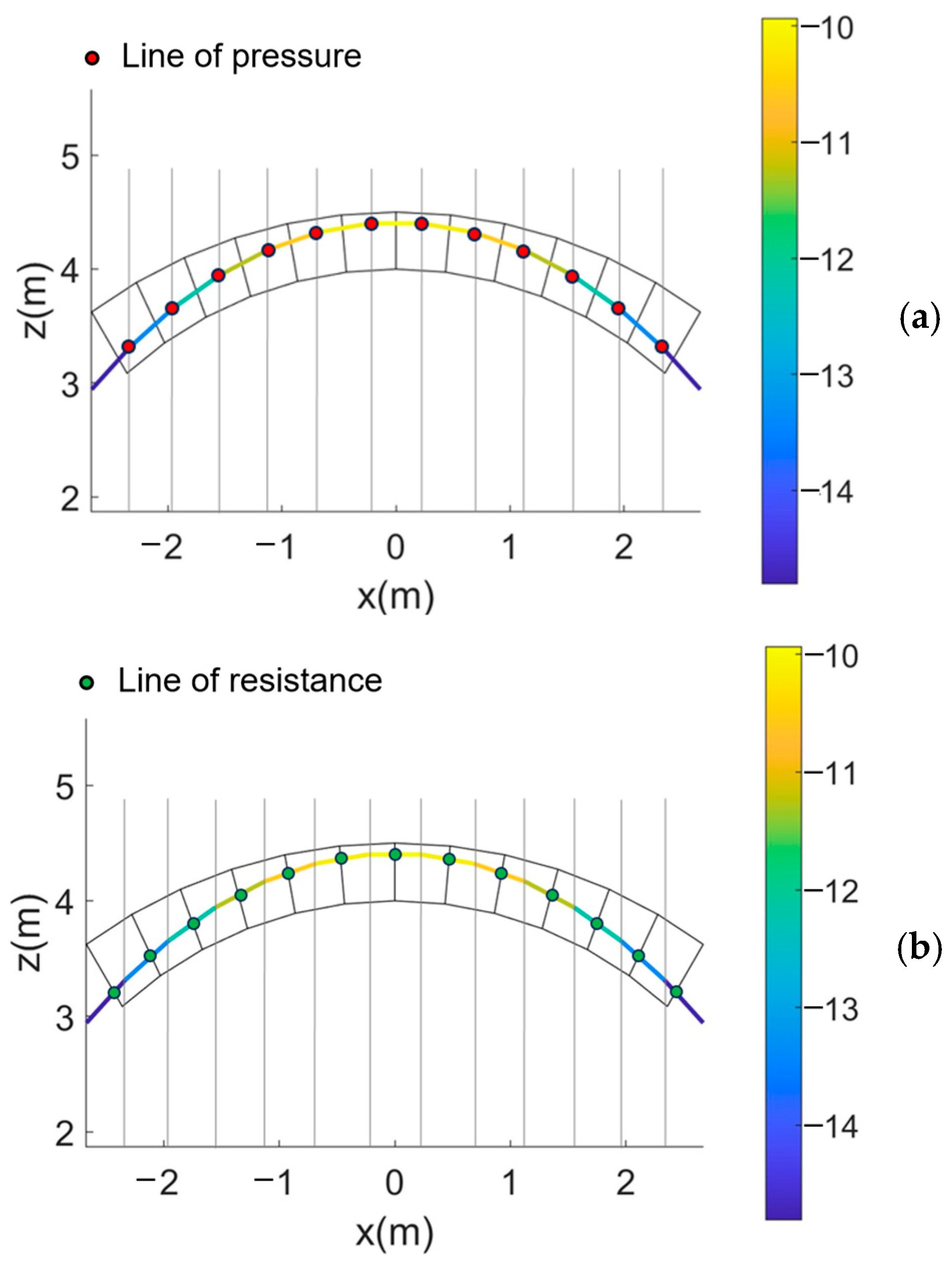
Focusing momentarily on recent contributions that incorporate the compressive strength of the material into the thrust line method, the distinction between the two interpretations of the thrust line concept, namely the ‘line of resistance’ and ‘line of pressure’, can be succinctly illustrated by recalling a computational anti-funicular approach that accounts for the influence of strength requirements on the structural response of masonry vaulted structures. The starting point is the formulation proposed by Bruggi [77] based on mathematical programming, which revisits and extends the concept of ‘line of pressure’ according to an approach deriving from the context of Thrust Network Analysis (see Section 2.2). For a masonry vault subjected to gravitational loads, the equilibrium of the network’s loaded nodes, whose vertices lie along vertical lines that pass through the centroids of the voussoirs, is handled by exploiting the concept of force density. The solution—corresponding to the minimum/maximum thrust or to the collapse load multiplier depending on the purposes of the investigation—is found by solving a multi-constrained optimization problem for the resulting grid with fixed plan projection, formulated in terms of any set of independent force densities and the height of the restrained nodes. The method—capable of analysing three-dimensional masonry structures under generic load conditions—can be applied to the assessment of masonry arches (Figure 9) tracing the ‘line of pressure’ corresponding to the solution: the red dots in Figure 9a are the nodes of the anti-funicular polygon. To introduce the limited compressive strength, local constraints are set at each joint according to the formulation proposed in [73,74,75], the respect of which refers to the concept of ‘line of resistance’; see the green dots in Figure 9b. It is worthy to note that the force density approach uses maximization to determine the collapse load by allowing for a one-shot solution. The fixed plan projection assumption guarantees a numerically effective optimization problem with low computational costs.
The two limit analysis procedures based on the thrust line concept outlined above [71,72,73,74,75,77] were chosen to clarify the theoretical distinctions between historical approaches and modern formulations, thus illustrating the concepts of ‘line of resistance’ and ‘line of pressure’. These contributions, framed in the static approach of limit analysis, are part of a body of research combining limited compressive strength in the thrust line approach, which has recently attracted attention, as indicated by many contributions on vaulted masonry structures.
Among the studies which exploit the lower bound theorem of limit analysis, ref. [78] extend the Thrust Network Analysis in order to take into account the masonry strength by defining a local and global safety factor; ref. [79] proposes a procedure to assess the bearing capacity of masonry arches by considering modifications in the geometric domain of the thrust line to include the limited compressive strength. Furthermore, the method takes into account the effects of tensile strength, due to the reinforcements, and delamination of the composite material. The starting point is a computational formulation of the funicular polygon, i.e., revisiting the concept of ‘line of pressure’; with reference to unreinforced arches, the ultimate limit state for any arch’s joint is defined by considering strength domains analogous to those plotted in Figure 7b,c, in the N i , M i , ξ plane and in the N i , e i , ξ plane, respectively, with some adaptations depending on the different design specifications. The analysis proposes an iterative procedure assuming initial eccentricity limits corresponding to the intrados and extrados of the joints. Developing a first tentative thrust line analysis, the solution is iteratively updated by considering the limit bending moment at each joint.
For completeness, another set of studies is recalled that introduces the compressive strength starting from the upper bound theorem of limit analysis; the thrust line is derived in a second step, enforcing the strength limitations. Among these contributions, the pioneering work of [80] proposes a geometric safety factor to take into account, albeit approximately, the limited strength in masonry arches; refs. [81,82] refer to both strengthened and unstrengthened arches; ref. [83] proposes an iterative procedure to examine masonry arches subjected to seismic loads, which starts with the assignment of a first mechanism and the corresponding virtual displacement diagrams; knowing the loading conditions simplifies the determination of the external reactions and the thrust line passing through the yield zones. Finally, ref. [84] applies the kinematic limit analysis assuming the masonry compressive strength as a stochastic variable.

2.2. Further Developments of the Thrust Line Method

Heyman’s treatment of masonry structures provided a solid foundation for the development of contemporary computational techniques based on limit analysis, leveraging both static and kinematic theorems. As noted in Section 2.1, modern approaches that utilize the thrust line concept and account for the finite compressive strength of masonry have also been inspired by Heyman’s theoretical framework.
It is worth noting that considering the compressive strength is not the only possible development of the thrust line approach. In this regard, several scholars underline the adequacy of the formulations based on the simplified assumptions adopted by Heyman to satisfactorily describe most masonry structures, for which the structural behaviour can be described with good approximation by considering an infinite compressive strength [21,22,24].
A full discussion of the possible advances in thrust line applications is beyond the scope of this paper. The reader is encouraged to consult [11,12,13,20,41,42] to gain an idea of the complexity of the topic. Below is a brief and necessarily incomplete overview of the recent state of the art on this subject.
Some approaches based on thrust line aim to provide analytical or numerical methods to solve classical problems related to the equilibrium of masonry arch. Without claiming completeness, it is enough to mention iterative procedures for finding the minimum thickness of an arch, based on both the lower and upper bound theorem of limit analysis [85], the development of effective computational procedures for thrust line analysis, also used for optimization purposes [86,87], and the reworking of the Milankovitch [88] approach by means of analytical or variational formulations [89,90]. Recent research introduces the notion of ‘thrust layout’ [91], which brings together the definitions of ‘line of resistance’ and ‘line of pressure’, confirming the interest of the topic also in today’s scientific literature.
Thrust line analysis is also used to study the equilibrium of masonry domes of revolution, starting with the contributions by Eddy [92] and Wolfe [93]. According to the ‘slicing technique’ re-discovered by Heyman [18] and developed by various authors [25,94], masonry domes can be schematized as composed of independent adjacent ‘lunes’, each of which is seen as a semi-arch of varying width. If the thrust line associated with a single ‘lune’ is contained inside the dome meridian profile, equilibrium is ensured under the simplifying assumption of zero tensile hoop forces. The collapse condition is defined by considering whether the limit condition obtained from the thrust line related to the single ‘lune’ is compatible with a kinematically admissible collapse mechanism for the entire dome. With reference to masonry domes, some recent contributions extend the thrust line method by reinterpreting the membrane theory [94,95], searching for thrust surfaces [96] or deriving truss-like stress paths from Airy stress functions [97].
An important development of the thrust line concept is provided by the body of studies based on the concept of Thrust Network Analysis, which allows one to study the structural response of more complex geometries with three-dimensional behaviour. This approach, grounded in graphical statics [98,99,100], and its recent developments [24,34,101,102,103] refer to the concept of ‘line of pressure’. The equilibrium in masonry systems is depicted as a network of resulting compression forces confined within the structure’s thickness, which provides the force flow within the structure. As observed by [24], in a working condition, any network in equilibrium with the assigned loads represents only one of the infinite possible solutions.
The above-cited studies are based on the Heyman hypotheses [16,17,18], which capture in a simplified way fundamental properties of the masonry material, i.e., a good compressive strength and a negligible tensile strength. A further enrichment of the Heyman model, to describe the mechanical response of some thick vaults or flat arches, can be derived from the consideration of a limited friction between the voussoirs. For this reason, based on studies on non-standard plastic behaviour [48,49,50,51], recent research reinterprets the thrust line method by exploring the impact of bounded friction on the collapse behaviour of masonry arches and vaults considering a finite or infinite compressive strength [104,105,106,107,108,109]. These contributions discuss the challenges of using a lower bound approach to accurately capture the mechanical behaviour of masonry structures under the hypothesis of finite friction and highlight the importance of combining equilibrium analyses with kinematic/dynamic investigations. In this regard, outside the methods strictly related to the thrust line concept, we can mention [110], where the authors consider the presence of finite friction between the voussoirs by means of a regularized non-smooth contact dynamics approach.
Finally, theoretical difficulties on the application of the static approach and the thrust line method are investigated by [111]: for some simple examples of assemblies of rigid block structures, the safe theorem fails, i.e., collapse occurs despite the existence of an equilibrium force system.

3. Conclusions and Prospects

The concepts of ‘line of resistance’ and ‘line of pressure’ [43,44]—based, respectively, on the Coulomb maximis and minimis method [19] and the inverted catenary notion [47]—are powerful tools for assessing both the structural safety and the load-bearing capacity of masonry arches and vaults.
The recent scientific literature includes several contributions that revisit these concepts by adopting Heyman’s hypotheses [16,17,18], from numerical or graphical approaches to differential or variational formulations [85,86,87,88,89,90], which demonstrates their potential for exploring the equilibrium of both two- and three-dimensional masonry structures [22,23,24,25,92,93,94,95,96,97,98,99,100,101,102,103,104].
In this entry paper, attention is paid to those formulations of the thrust line method that consider a limited compressive strength by describing both selected historical approaches [38,70], according to which the ‘limit’ condition is traced back to a linear ‘elastic’ distribution of the stresses along the joint’s depth, and modern developments, grounded on a different theoretical framework, i.e., limit analysis, where the assumption of a compressive strength can be seen as an enrichment of Heyman’s hypotheses [16,17,18]. The rediscovery of the pre-elastic contributions, carried out by Heyman [16], allowed clearly incorporation of the thrust line method into the theoretical paradigm of limit analysis, clarifying the ambiguities linked to previous historical formulations that had been influenced by the elastic theory.
To illustrate this aspect, the original approach proposed by Durand-Claye [70] and its modern reinterpretation [71,72,73,74,75] are compared: The graphical procedure is revisited in terms of stress resultants, imposing a limit condition on the bending moment corresponding to a stress block rather than a linear distribution. The concept of ‘line of resistance’ is exploited by considering the eccentricity of both the horizontal thrust at the ideal vertical crown section and the internal force acting on any joint. Conversely, the concept of ‘line of pressure’ is the starting point of recent contributions that develop funicular methods, which include thrust line analysis [22,23,85,86,87,88,89,90] and Thrust Network Analysis for the assessment of structures with complex geometry [24,77,98,99,100,101,102,103].
The introduction of a limited compressive strength imposes strength requirements at each joint and affects the ‘line of resistance’, while the consideration of finite friction refers to the ‘line of pressure’ and leads to theoretical challenges related to non-standard plastic behaviour.
Thrust line analysis, thanks to its versatility, can be further extended by considering different assumptions regarding the joint’s flexural or shear capacity, with reference to both strengthened and unstrengthened masonry arches. Furthermore, methods based on thrust line analysis lend themselves to semi-analytical or numerical formulations suitable for exploring the role of uncertainties in masonry strength through probabilistic approaches. Possible developments in this research could be aimed at generalizing local strength domains to capture the effects of geometric and mechanical uncertainties and the impact of damage on the arch’s structural response. Furthermore, the related concepts of ‘line of pressure’ and ‘line of resistance’ provide the foundation for advances aimed at studying masonry structures with complex geometry introducing aspects related to masonry strength both under gravitational and seismic loads.
Finally, we observe how—despite the complexity of modelling the masonry material—the need to preserve the architectural heritage has led to a growing demand for simple procedures for the stability assessment of masonry vaulted structures. While refined FEM/DEM models are usually computationally demanding and require knowledge of multiple mechanical parameters to be calibrated correctly, simpler approaches based on the theoretical framework of limit analysis are considered reliable in engineering practice even today to determine the safety factor of masonry structures in relation to the collapse condition. In this perspective, the thrust line method and its modern developments can offer a significant contribution.

Funding

This research received no external funding.

Institutional Review Board Statement

Not applicable.

Informed Consent Statement

Not applicable.

Data Availability Statement

Data sharing is not applicable to this article.

Conflicts of Interest

The author declares no conflicts of interest.

References

  1. Lourenço, P.B.; Pina-Henriques, J. Validation of analytical and continuum numerical methods for estimating the compressive strength of masonry. Comput. Struct. 2006, 84, 1977–1989. [Google Scholar] [CrossRef] [Scilit]
  2. Pelà, L.; Canella, E.; Aprile, A.; Roca, P. Compression test of masonry core samples extracted from existing brickwork. Constr. Build. Mater. 2016, 119, 230–240. [Google Scholar] [CrossRef] [Scilit]
  3. Benedetti, A.; Tarozzi, M. Compressive strength of heterogeneous masonry walls containing blends of brick types. Mater. Struct. 2022, 55, 71. [Google Scholar] [CrossRef] [Scilit]
  4. Al-Ahdal, A.; AbdelRahman, B.; Galal, H. Compressive, shear, and tensile behaviours of concrete masonry: Experimental and numerical study. Constr. Build. Mater. 2025, 458, 139266. [Google Scholar] [CrossRef] [Scilit]
  5. Tóth, A.R.; Orbán, Z.; Bagi, K. Discrete element analysis of a stone masonry arch. Mech. Res. Commun. 2009, 36, 469–480. [Google Scholar] [CrossRef] [Scilit]
  6. Masi, F.; Stefanou, I.; Maffi-Berthier, V.; Vannucci, P. A Discrete Element Method based-approach for arched masonry structures under blast loads. Eng. Struct. 2020, 216, 110721. [Google Scholar] [CrossRef] [Scilit]
  7. Pulatsu, B.; Gonen, S.; Lourenço, P.B. Static and Impact Response of a Single-Span Stone Masonry Arch. Infrastructures 2021, 6, 178. [Google Scholar] [CrossRef] [Scilit]
  8. Lubowiecka, I.; Armesto, J.; Arias, P.; Lorenzo, H. Historic bridge modelling using laser scanning, ground penetrating radar and finite element methods in the context of structural dynamics. Eng. Struct. 2009, 31, 2667–2676. [Google Scholar] [CrossRef] [Scilit]
  9. Pingaro, N.; Milani, G. Simple non-linear numerical modelling of masonry arches reinforced with SRG using elasto-fragile and elasto-ductile truss finite elements. Eng. Struct. 2023, 293, 116637. [Google Scholar] [CrossRef] [Scilit]
  10. Tarhan, İ.H.; Savalle, N.; Uysal, H.; Canditone, C.; da Silva, L.C.M.; Lourenço, P.B. Experimental and numerical investigation on the effect of pre-existing damage in the seismic capacity of masonry arches. Eng. Struct. 2025, 345, 121320. [Google Scholar] [CrossRef] [Scilit]
  11. Angelillo, M.; Lourenço, P.B.; Milani, G. Masonry Behaviour and Modelling; Mechanics of Masonry Structures; CISM International Centre for Mechanical Sciences Courses and Lectures; Angelillo, M., Ed.; Springer: Vienna, Austria, 2014; Volume 551, pp. 1–26. [Google Scholar] [CrossRef] [Scilit]
  12. D’Altri, A.M.; Sarhosis, V.; Milani, G.; Rots, J.; Cattari, S.; Lagomarsino, S.; Sacco, E.; Tralli, A.; Castellazzi, G.; de Miranda, S. Modeling strategies for the computational analysis of unreinforced masonry structures: Review and classification. Arch. Comput. Methods Eng. 2020, 27, 1153–1185. [Google Scholar] [CrossRef] [Scilit]
  13. Castellazzi, G.; Taliercio, A. Principles and Analysis of Historical Masonry Structures: The Strength of the Past; Cambridge Scholars Publishing: Cambridge, UK, 2025. [Google Scholar]
  14. Buzzetti, M.; Pingaro, N.; Milani, G. Automatic detection of local collapse mechanisms in historical masonry buildings: Fast and robust FE upper bound limit analysis. Eng. Fail. Anal. 2025, 170, 109310. [Google Scholar] [CrossRef] [Scilit]
  15. Kooharian, A. Limit analysis of voussoirs (segmental) and concrete arches. J. Proc. Am. Concr. Inst. 1952, 24, 217–328. [Google Scholar]
  16. Heyman, J. The stone skeleton. Int. J. Solids Struct. 1966, 2, 249–279. [Google Scholar] [CrossRef] [Scilit]
  17. Heyman, J. The safety of masonry arches. Int. J. Mech. Sci. 1969, 11, 363–385. [Google Scholar] [CrossRef] [Scilit]
  18. Heyman, J. Equilibrium of Shell Structures; Oxford University Press: Oxford, UK, 1977. [Google Scholar]
  19. Coulomb, C.A. Essai sur une Application des Règles de Maximis et Minimis à Quelques Problèmes de Statique, Relatifs à l’Architecture. Mémoires Mathématique Phys. 1776, 7, 343–382. [Google Scholar]
  20. Como, M. Statics of Historic Masonry Constructions; Springer Series in Solid and Structural Mechanics; Springer: Cham, Switzerland, 2017; Volume 9. [Google Scholar]
  21. Huerta, S. Galileo was wrong: The geometrical design of masonry arches. Nexus Netw. J. 2006, 8, 25–52. [Google Scholar] [CrossRef] [Scilit]
  22. Rondeaux, J.-F.; Deschuyteneer, A.; Zastavni, D. Assessing geometrically the structural safety of masonry arches. In Building Knowledge, Constructing Histories, Proceedings of the 6th International Congress on Construction History (6ICCH 2018), 9–13 July 2018, Brussels, Belgium, 1st ed.; Wouters, I., Voorde, S., Bertels, I., Espion, B., Jonge, K., Zastavni, D., Eds.; CRC Press: London, UK, 2018; pp. 1129–1136. [Google Scholar]
  23. Zampieri, P.; Niero, L.; Pellegrino, C. The thrust line in masonry arches: A new simplified algorithm. Struct. Infrastruct. Eng. 2024, 1–14. [Google Scholar] [CrossRef] [Scilit]
  24. Maia Avelino, R.; Yang, W.; Weichbrodt, A.; Ochsendorf, J.; Flatt, R.J. Augmented Reality for Structural Inspection of Historic Monuments: The Case of Lausanne Cathedral. Int. J. Arch. Herit. 2025, 1–16. [Google Scholar] [CrossRef] [Scilit]
  25. Oppenheim, I. The masonry arch as a four-link mechanism under base motion. Earthq. Eng. Struct. Dyn. 1992, 21, 1005–1017. [Google Scholar] [CrossRef] [Scilit]
  26. Dimitri, R.; Tornabene, F. A parametric investigation of the seismic capacity for masonry arches and portals of different shapes. Eng. Fail. Anal. 2015, 52, 1–34. [Google Scholar] [CrossRef] [Scilit]
  27. Misseri, G.; DeJong, M.J.; Rovero, L. Experimental and numerical investigation of the collapse of pointed masonry arches under quasi-static horizontal loading. Eng. Struct. 2018, 173, 180–190. [Google Scholar] [CrossRef] [Scilit]
  28. De Lorenzis, L.; Dejong, M.J.; Ochsendorf, J. Failure of masonry arches under impulse base motion. Earthq. Eng. Struct. Dyn. 2007, 36, 2119–2136. [Google Scholar] [CrossRef] [Scilit]
  29. Boothby, T.E.; Coronelli, D. The Stone Skeleton: A Reappraisal. Heritage 2024, 7, 2265–2276. [Google Scholar] [CrossRef] [Scilit]
  30. Foraboschi, P.; Vanin, A. Experimental investigation on bricks from historical Venetian buildings subjected to moisture and salt crystallization. Eng. Fail. Anal. 2014, 45, 185–203. [Google Scholar] [CrossRef] [Scilit]
  31. Sarhosis, V.; De Santis, S.; de Felice, G. A review of experimental investigations and assessment methods for masonry arch bridges. Struct. Infrastruct. Eng. 2016, 12, 1439–1464. [Google Scholar] [CrossRef] [Scilit]
  32. Saviano, F.; Lignola, G.P.; Parisi, F. Experimental compressive and shear behaviour of clay brick masonry with degraded joints. Constr. Build. Mater. 2024, 452, 138880. [Google Scholar] [CrossRef] [Scilit]
  33. Briccoli Bati, S.; Rovero, L. Towards a methodology for estimating strength and collapse mechanism in masonry arches strengthened with fibre reinforced polymer applied on external surfaces. Mater. Struct. 2008, 41, 1291–1306. [Google Scholar] [CrossRef] [Scilit]
  34. Dahmen, J.F.D.; Ochsendorf, J.A. Earth Masonry Structures: Arches, Vaults and Domes. In Modern Earth Buildings Materials, Engineering, Constructions and Applications; Hall, M.R., Lindsay, R., Krayenhoff, M., Eds.; Woodhead Publishing Series in Energy, Modern Earth Buildings; Woodhead Publishing: Sawston, Cambridge, UK, 2012; pp. 427–460. [Google Scholar]
  35. Liu, B.; Sarhosis, V.; Booth, A.D.; Gilbert, M. The 3D response of a large-scale masonry arch bridge—Part II: Performance at failure. Eng. Struct. 2024, 313, 118308. [Google Scholar] [CrossRef] [Scilit]
  36. Aita, D.; Milani, G.; Taliercio, A. Fast Limit Analysis of Domes Belonging to the Architectural Heritage Under Different Hypotheses on Masonry Strength. Int. J. Arch. Herit. 2024, 19, 2248–2280. [Google Scholar] [CrossRef] [Scilit]
  37. Gandolfi, A.; Pingaro, N.; Milani, G. Elastic Body Spring Method (EBSM) for the Stability Analysis of the Global Vipassana Pagoda in Mumbai, India. Buildings 2025, 15, 653. [Google Scholar] [CrossRef] [Scilit]
  38. Méry, E. Sur l’équilibre des voûtes en berceau. Ann. Ponts Chaussées 1840, 19, 50–70. [Google Scholar]
  39. Ageno, A.; Bernabò, A.; Foce, F.; Sinopoli, A. Theory and History of the Thrust Line for Masonry Arches. A Brief Account. In Arch Bridges IV. Advances in Assessment, Structural Design and Construction; Roca, P., Molins, C., Eds.; CIMNE: Barcelona, Spain, 2004; pp. 1–10. [Google Scholar]
  40. Gaspar, O.; Sajtos, I. On the Definition of the Line of Thrust. In Structural Analysis of Historical Constructions: Anamnesis, Diagnosis, Therapy, Controls, Proceedings of the 10th International Conference on Structural Analysis of Historical Constructions SAHC, Leuven, Belgium, 13–15 September 2016, 1st ed.; Van Balen, K., Verstrynge, E., Eds.; CRC Press: London, UK, 2016; pp. 1003–1010. [Google Scholar]
  41. Milani, G.; Sarhosis, V. (Eds.) From Corbel Arches to Double Curvature Vaults. Research for Development; Springer: Cham, Switzerland, 2022. [Google Scholar]
  42. Bagi, K.; Angelillo, M. (Eds.) Discrete Computational Mechanics of Masonry Structures; CISM International Centre for Mechanical Sciences; Springer: Cham, Switzerland, 2023; Volume 609. [Google Scholar]
  43. Gerstner, F.J. Handbuch der Mechanik; J. Spurny: Prague, Czech Republic, 1831. [Google Scholar]
  44. Moseley, H. The Mechanical Principles of Engineering and Architecture; Longman, Brown, Green, and Longmans: London, UK, 1843. [Google Scholar]
  45. De La Hire, P. Sur la Construction des Voûtes dans les Édifices. Mémoires L’académie R. Sci. 1731, 69–77.
  46. Mascheroni, L. Nuove Ricerche Sull’equilibrio delle Volte; Locatelli: Bergamo, Italy, 1785. [Google Scholar]
  47. Hooke, R. A Description of Helioscopes, and Some Other Instruments; John & Martin Printer to the Royal Society: London, UK, 1675. [Google Scholar]
  48. Drucker, D.C. Limit analysis of two and three dimensional soil mechanics problems. J. Mech. Phys. Solids 1953, 1, 217–226. [Google Scholar] [CrossRef] [Scilit]
  49. Drucker, D.C. Coulomb Friction, Plasticity, and Limit Loads. ASME J. Appl. Mech. 1954, 21, 71–74. [Google Scholar] [CrossRef] [Scilit]
  50. Radenkovic, D. Théorèmes limites pour un materiau de Coulomb à dilatiation non standardisée. Comptes Rendus Math. Acad. Sci. Paris 1961, 252, 4103–4104. [Google Scholar]
  51. Gilbert, M.; Casapulla, C.; Ahmed, H.M. Limit analysis of masonry block structures with non-associative frictional joints using linear programming. Comput. Struct. 2006, 84, 873–887. [Google Scholar] [CrossRef] [Scilit]
  52. Navier, C.L.M.H. Résumé des Leçons Données à l’Ecole des Ponts et Chaussées sur l’Application de la Mécanique à l’Établissement des Constructions et des Machines; Didot: Paris, France, 1826. [Google Scholar]
  53. Cauchy, A. L Exercices de Mathématiques; De Bure Frères: Paris, France; pp. 1826–1829.
  54. Poisson, S.D. Mémoire sur l’équilibre et le mouvement des corps élastiques. Mémoires l’Académie R. Sci. L’institut Fr. 1829, 8, 357–570. [Google Scholar]
  55. Lamé, G.; Clapeyron, E. Mémoire sur l’Équilibre Intérieur des Corps Solides Homogènes. Sci. Mathématiques Phys. 1833, 4, 465–562. [Google Scholar]
  56. Barlow, W.H. On the existence (practically) of the line of equal horizontal thrust in arches, and the mode of determining it by geometrical constructions. Minutes Proc. Inst. Civ. Eng. 1846, 5, 162–172. [Google Scholar] [CrossRef] [Scilit]
  57. Denfert-Rocherau, A. Mémoire sur les voûtes en berceau portant une surcharge limitée à un plan horizontal. Révue de L’architecture Trav. Publics 1859, 17, 114–124, 158–179, 207–224, 257–268. [Google Scholar]
  58. Scheffler, H. Theorie der Gewölbe, Futtermauern und Eisernen Brücken; Verlag der Schulbuchhandlung: Brunswick, Germany, 1857. [Google Scholar]
  59. Drouets. Sur la stabilité des voûtes. Ann. Ponts Chaussées 1865, 9, 179–266. [Google Scholar]
  60. Dupuit, J. Traité de l’Équilibre des Voûtes; Dunod: Paris, France, 1870. [Google Scholar]
  61. Laterrade. Note sur la stabilité des voûtes en réponse à un travail de M. Léon Durand-Claye. Ann. Ponts Chaussées 1885, 10, 1004–1006. [Google Scholar]
  62. Crotti, F. Esame Critico di una Recente Deliberazione dell’Istituto Lombardo delle Scienze circa la Teoria delle Volte; Civelli: Milan, Italy, 1875. [Google Scholar]
  63. Castigliano, A. Applicazioni Pratiche della Teoria sui Sistemi Elastici; Studi dell’Ufficio d’Arte, Strade Ferrate dell’Alta Italia, Servizio della Manutenzione e dei Lavori; Civelli: Milan, Italy, 1878. [Google Scholar]
  64. Castigliano, A. Théorie de l’Équilibre des Systèmes Élastiques et ses Applications; A. F. Negro: Turin, Italy, 1879. [Google Scholar]
  65. Benvenuto, E. La Scienza delle Costruzioni e il suo Sviluppo Storico; Sansoni: Florence, Italy, 1981; pp. 369–381. [Google Scholar]
  66. Benvenuto, E. An Introduction to the History of Structural Mechanics, Part II. Vaulted Structures and Elastic Systems; Springer: New York, NY, USA, 1991; pp. 412–425. [Google Scholar]
  67. Foce, F.; Sinopoli, A. Le svolte di pensiero nella riflessione scientifica sulla statica degli archi in muratura. Costr. Laterizio 1996, 9, 180–184. [Google Scholar]
  68. Foce, F. Sulla Teoria dell’arco Murario. Una Rilettura Storico-Critica. In Degli Archi e delle Volte. Arte del Costruire tra Meccanica e Stereotomia; Becchi, A., Foce, F., Eds.; Marsilio: Venice, Italy, 2002. [Google Scholar]
  69. Kurrer, K.E. The History of the Theory of Structures; Ernst & Sohn: Berlin, Germany, 2008. [Google Scholar]
  70. Durand-Claye, A. Note sur la vérification de la stabilité des voûtes en maçonnerie et sur l’emploi des courbes de pression. Ann. Ponts Chaussées 1867, 13, 63–93. [Google Scholar]
  71. Aita, D.; Barsotti, R.; Bennati, S. Equilibrium of pointed, circular, and elliptical masonry arches bearing vertical walls. J. Struct. Eng. 2012, 138, 880–888. [Google Scholar] [CrossRef] [Scilit]
  72. Aita, D.; Barsotti, R.; Bennati, S. Looking at the collapse modes of circular and pointed masonry arches through the lens of Durand–Claye’s stability area method. Arch. Appl. Mech. 2019, 89, 1537–1554. [Google Scholar] [CrossRef] [Scilit]
  73. Aita, D.; Bruggi, M. A numerical method for the funicular analysis of masonry vaults accounting for stereotomy, finite strength and finite friction. Eng. Struct. 2023, 293, 116658. [Google Scholar] [CrossRef] [Scilit]
  74. Aita, D.; Bruggi, M.; Garavaglia, E. Collapse analysis of masonry arches and domes considering finite friction and uncertainties in compressive strength. Eng. Fail. Anal. 2024, 163, 108462. [Google Scholar] [CrossRef] [Scilit]
  75. Aita, D.; Bruggi, M.; Taliercio, A. Limit analysis of masonry arches and domes with finite strength: Funicular analysis versus stability area method. Meccanica 2025, 60, 601–620. [Google Scholar] [CrossRef] [Scilit]
  76. Livesley, R.K. Limit analysis of structures formed from rigid blocks. Int. J. Numer. Methods Eng. 1978, 12, 1853–1871. [Google Scholar] [CrossRef] [Scilit]
  77. Bruggi, M. A constrained force density method for the funicular analysis and design of arches, domes and vaults. Int. J. Solids Struct. 2020, 193–194, 251–269. [Google Scholar] [CrossRef] [Scilit]
  78. Fantin, M.; Ciblac, T. Extension of thrust network analysis with joints consideration and new equilibrium states. Int. J. Space Struct. 2016, 31, 190–202. [Google Scholar] [CrossRef] [Scilit]
  79. Pellecchia, D.; Marmo, F.; Rosati, L. Accounting for material strength in the thrust line analyses of unstrengthened and strengthened arches. Compos. Struct. 2025, 358, 118926. [Google Scholar] [CrossRef] [Scilit]
  80. Harvey, W.J. Application of the mechanism analysis to masonry arches. Struct. Eng. 1988, 66, 77–84. [Google Scholar]
  81. Caporale, A.; Luciano, R. Limit analysis of masonry arches with finite compressive strength and externally bonded reinforcement. Compos. B Eng. 2012, 43, 3131–3145. [Google Scholar] [CrossRef] [Scilit]
  82. Nela, B.; Jiménez Rios, A.; Pingaro, M.; Reccia, E.; Trovalusci, P. Limit analysis of locally reinforced masonry arches. Eng. Struct. 2022, 271, 114921. [Google Scholar] [CrossRef] [Scilit]
  83. Clemente, P.; Saitta, F.; Buffarini, G.; Ormando, C. Masonry Arch Bridges with Finite Compression Strength Subject to Horizontal Longitudinal Seismic Actions. Appl. Sci. 2023, 13, 7509. [Google Scholar] [CrossRef] [Scilit]
  84. Brencich, A.; Gambarotta, L.; Sterpi, E. Stochastic distribution of compressive strength: Effects on the load carrying capacity of masonry arches. In Proceedings of the International Conference on Arch Bridges, Madeira, Portugal, 13–16 September 2007; pp. 641–648. [Google Scholar]
  85. Clemente, P.; Occhiuzzi, A.; Raithel, A. Limit behavior of stone arch bridges. J. Struct. Eng. ASCE 1995, 121, 1045–1050. [Google Scholar] [CrossRef] [Scilit]
  86. Nodargi, N.A.; Bisegna, P. Thrust line analysis revisited and applied to optimization of masonry arches. Int. J. Mech. Sci. 2020, 179, 105690. [Google Scholar] [CrossRef] [Scilit]
  87. Marmo, F. ArchLab: A MATLAB tool for the thrust line analysis of masonry arches. Curved Layer. Struct. 2021, 8, 26–35. [Google Scholar] [CrossRef] [Scilit]
  88. Milankovitch, M. Theorie der Drukkurven. Z. Math. Phys. 1907, 55, 1–27. [Google Scholar]
  89. Makris, N.; Alexakis, H. The effect of stereotomy on the shape of the thrust-line and the minimum thickness of semicircular masonry arches. Arch. Appl. Mech. 2013, 83, 1511–1533. [Google Scholar] [CrossRef] [Scilit]
  90. Nikolić, D. Thrust line analysis and the minimum thickness of pointed masonry arches. Acta Mech. 2017, 228, 2219–2236. [Google Scholar] [CrossRef] [Scilit]
  91. Nanayakkara, K.I.U.; Liew, A.; Gilbert, M. Thrust layouts in masonry gravity structures. Int. J. Solids Struct. 2025, 323, 113593. [Google Scholar] [CrossRef] [Scilit]
  92. Eddy, H.T. New Constructions in Graphical Statics; Van Nostrand: New York, NY, USA, 1877. [Google Scholar]
  93. Wolfe, W.S. Graphical Analysis. A Text Book on Graphic Statics; McGrow-Hill Book Co.: New York, NY, USA, 1921. [Google Scholar]
  94. Galassi, S.; Misseri, G.; Rovero, L.; Tempesta, G. Equilibrium analysis of masonry domes. On the analytical interpretation of the Eddy-Lévy graphical method. Int. J. Arch. Herit. 2017, 11, 1195–1211. [Google Scholar] [CrossRef] [Scilit]
  95. Cusano, C.; Montanino, A.; Olivieri, C.; Paris, V.; Cennamo, C. Graphical and Analytical Quantitative Comparison in the Domes Assessment: The Case of San Francesco di Paola. Appl. Sci. 2021, 11, 3622. [Google Scholar] [CrossRef] [Scilit]
  96. Barsi, F.; Barsotti, R.; Bennati, S. Studying the equilibrium of oval-base pointed masonry domes: The case of Pisa Cathedral. Int. J. Mason. Res. Innov. 2022, 7, 146–171. [Google Scholar] [CrossRef] [Scilit]
  97. Angelillo, M.; Babilio, E.; Fortunato, A. Singular stress fields for masonry-like vaults. Contin. Mech. Thermodyn. 2013, 25, 423–441. [Google Scholar] [CrossRef] [Scilit]
  98. O’Dwyer, D. Funicular analysis of masonry vaults. Comput. Struct. 1999, 73, 187–197. [Google Scholar] [CrossRef] [Scilit]
  99. Block, P.; DeJong, M.; Ochsendorf, J. As hangs the flexible line: Equilibrium of masonry arches. Nexus Netw. J. 2006, 8, 13–24. [Google Scholar] [CrossRef] [Scilit]
  100. Block, P.; Lachauer, L. Three-dimensional (3D) equilibrium analysis of Gothic masonry vaults. Int. J. Arch. Herit. 2014, 8, 312–335. [Google Scholar] [CrossRef] [Scilit]
  101. Marmo, F.; Masi, D.; Rosati, L. Thrust network analysis of masonry helical staircases. Int. J. Arch. Herit. 2018, 12, 828–848. [Google Scholar] [CrossRef] [Scilit]
  102. Nodargi, N.A.; Bisegna, P. Generalized thrust network analysis for the safety assessment of vaulted masonry structures. Eng. Struct. 2022, 270, 114878. [Google Scholar] [CrossRef] [Scilit]
  103. Maia Avelino, R.; Iannuzzo, A.; Van Mele, T.; Block, P. Assessing the safety of vaulted masonry structures using thrust network analysis. Comput. Struct. 2021, 257, 106647. [Google Scholar] [CrossRef] [Scilit]
  104. Portioli, F.; Casapulla, C.; Cascini, L. An efficient solution procedure for crushing failure in 3D limit analysis of masonry block structures with non-associative frictional joints. Int. J. Solids Struct. 2015, 69–70, 252–266. [Google Scholar] [CrossRef] [Scilit]
  105. Cocchetti, G.; Rizzi, E. Nonlinear programming numerical formulation to acquire limit self-standing conditions of circular masonry arches accounting for limited friction. Int. J. Mason. Res. Innov. 2020, 5, 569–617. [Google Scholar] [CrossRef] [Scilit]
  106. Hua, Y.; Milani, G. Simple modeling of reinforced masonry arches for associated and non-associated heterogeneous limit analysis. Comput. Struct. 2023, 280, 106987. [Google Scholar] [CrossRef] [Scilit]
  107. Ting-Chun Kao, G.; Iannuzzo, A.; Thomaszewski, B.; Coros, S.; Van Mele, T.; Block, P. Coupled rigid-block analysis: Stability-aware design of complex discrete-element assemblies. Comput. Aided Des. 2022, 146, 103216. [Google Scholar]
  108. Trentadue, F.; De Tommasi, D.; Marasciuolo, N.; Vitucci, G. Thrust in a symmetric masonry arch with frictional joints on spreading supports. Acta Mech. 2024, 235, 659–670. [Google Scholar] [CrossRef] [Scilit]
  109. Aita, D.; Beatini, V.; Caruso, H.; Garavaglia, E.; Sgambi, L. Some remarks on non-standard plastic behaviour with Coulomb’s friction starting from an unconventional stone flat arch. Eng. Struct. 2025, 326, 119539. [Google Scholar] [CrossRef] [Scilit]
  110. Beatini, V.; Royer Carfagni, G.; Tasora, A. A regularized non-smooth contact dynamics approach for architectural masonry structures. Comput. Struct. 2017, 187, 88–100. [Google Scholar] [CrossRef] [Scilit]
  111. Bagi, K. When Heyman’s Safe Theorem of rigid block systems fails: Non-heymanian collapse modes of masonry structures. Int. J. Solids Struct. 2014, 51, 2696–2705. [Google Scholar] [CrossRef] [Scilit]
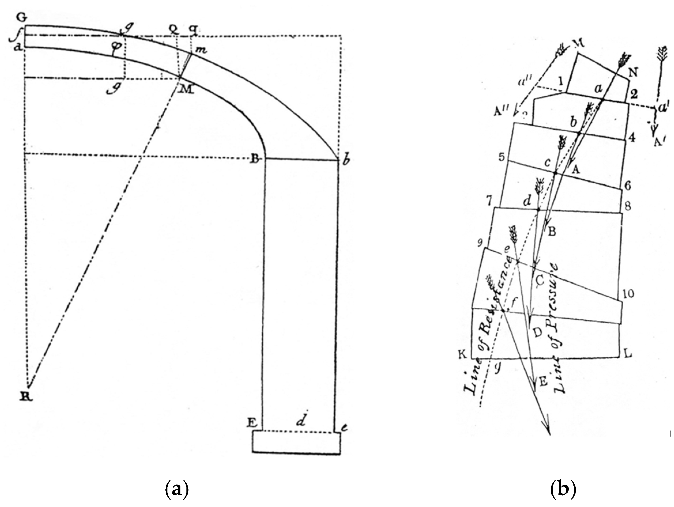
Figure 1. The half arch considered by Coulomb (1776) to impose the equilibrium conditions of the arch’s portion between the ideal vertical crown section aG and any joint Mm [19] (a). The concepts of ‘line of resistance’, defined by points a, b, c, …, and ‘line of pressure’, defined by points A, B, C, …, according to Moseley (1843), drawn from [44] (b).
Encyclopedia 06 00057 g001
Figure 2. Distribution of the normal stresses at any joint i (‘limit’ condition according to Méry): σ c is the compressive strength. The axes of inertia are denoted as ξ i and η i ; the vector n i is normal to the joint (a). Notation adopted by Méry for any joint i: dD is the joint’s depth; ND corresponds to the compressed portion of the joint (b); the resultant reaction, R i (of components R i , n and R i , η ) passes through point D′ (c) [38].
Encyclopedia 06 00057 g002
Figure 3. Méry contribution. Joint dD: centre of pressure, D′, and compressed portion of the joint, ND (left). Masonry arch: Extrados, BDA; intrados, bda; generic thrust line lying inside the thickness of the arch, β δ α ; the limits imposed by Méry to consider the finite compressive strength of masonry, B′D′A′ and b′d′a′ (right). Drawn from [38].
Encyclopedia 06 00057 g003
Figure 4. Symmetric arch with symmetric load conditions: eccentric horizontal thrust, f, acting on the ideal vertical crown section c 0 d 0 , and its eccentricity, e 0 (a); geometry of the joint (b); positive sign convention for the normal force, N i (c,d); its eccentricity e i , ξ (d); the shear force, T i (c,d), and the bending moment, M i , ξ (d).
Encyclopedia 06 00057 g004
Figure 5. Durand-Claye’s method: equilibrium of the arch’s portion comprised between joint c 0 d 0 and any joint i : rotational domain A i in the f , e 0 plane (a); the ‘limit’ condition for the bending capacity at any joint i in the N i , e i , ξ plane (b); the normal ( R i , n ) and tangential ( R i , η ) components of the internal reaction R i (c); representation of the ‘limit’ condition in the R i , n , e i , ξ plane (d) and in the N i , M i , ξ plane (e).
Encyclopedia 06 00057 g005
Figure 6. The stability area according to Durand-Claye, related to the entire arch; it is obtained by applying the procedure, aimed at defining all statically admissible solutions, to all the joints of the arch, c i d i (including the region c 0 ω 0 d 0 related to the vertical crown joint, c 0 d 0 ). Elaborated from [70]; for graphical clarity, the stability area has been coloured green.
Encyclopedia 06 00057 g006
Figure 7. Revisiting the Durand-Claye method in the context of limit analysis: limit stress distribution (a); local statically admissible domain in the N i , M i , ξ plane (b) and in the N i , e i , ξ plane (c).
Encyclopedia 06 00057 g007
Figure 8. Re-visitation of Durand-Claye’s method: rotational domain A i related to joint i, coloured in light yellow; the limit curves are denoted as − M i , ξ l i m (blue) and + M i , ξ l i m (red) (a); stability area A related to the entire arch, coloured in green, obtained by intersecting all the regions A i (b); ‘line of resistance’ corresponding to one of the infinitely many statically admissible solutions (c).
Encyclopedia 06 00057 g008
Figure 9. Anti-funicular polygon of minimum thrust (very low compressive strength, σ c = 0.1   M P a ), according to the anti-funicular method proposed in [73,74,75,77]: ‘line of pressure’ with the polygon nodes in red (a); the green dots identify the ‘line of resistance’ (b). The values of the forces in the branches (in kN) are shown by the colours.
Encyclopedia 06 00057 g009
Disclaimer/Publisher’s Note: The statements, opinions and data contained in all publications are solely those of the individual author(s) and contributor(s) and not of MDPI and/or the editor(s). MDPI and/or the editor(s) disclaim responsibility for any injury to people or property resulting from any ideas, methods, instructions or products referred to in the content.