


Abstract
Acoustic emission (AE) monitoring in metal additive manufacturing (AM) requires compact sensors capable of high-frequency operation, broad bandwidth, and high sensitivity. However, increasing structural stiffness to achieve high resonance frequencies typically reduces electromechanical sensitivity. This work presents a finite element study of a coupled-resonator capacitive micromachined ultrasonic transducer (CMUT) designed to address this trade-off. The proposed architecture integrates three mechanically coupled silicon membranes with a stepped capacitive cavity that increases capacitance while preserving structural stiffness, enabling enhanced sensitivity without compromising high-frequency operation. COMSOL Multiphysics simulations were used to evaluate modal characteristics and frequency response under DC pre-stressed conditions. Modal coupling produced closely spaced resonances that broadened the effective bandwidth, while the stepped cavity significantly increased voltage output through improved electromechanical coupling. Compared to a single-resonator flat-cavity design, the coupled stepped-cavity configuration demonstrated nearly a threefold enhancement in output voltage while maintaining operation near 100 kHz. Additionally, adjusting the central resonator length enabled controlled frequency tuning for scalable array implementation. These results establish a proof of concept for a high-frequency, high-sensitivity micro-electro-mechanical systems (MEMS) CMUT architecture suitable for distributed AE monitoring in advanced manufacturing environments.
Keywords:
CMUT; coupled-resonators; acoustic emissions; additive manufacturing; sensitivity; bandwidth; COMSOL 1. Introduction
Acoustic emission (AE) is a passive nondestructive testing (NDT) technique that enables real-time monitoring of damage evolution in structures and is increasingly explored for qualification and structural health monitoring of additively manufactured (AM) components [1,2]. AE signals are transient elastic waves produced by the rapid, localized release of strain energy, such as during microcrack initiation, crack growth, delamination, or plastic deformation under external stimuli (e.g., loading, pressure, or temperature) [3,4]. In AM, process-induced defects can degrade mechanical performance and introduce variability that is not reliably captured by visual inspection alone. As a result, AE has been proposed for in-process defect detection and for linking acoustic signatures to process parameters and resulting mechanical behavior [5].
Although conventional AE systems have demonstrated strong capability in laboratory-scale damage monitoring [6], their performance in complex and dynamic manufacturing environments remains constrained by sensor size and coupling dependence [7]. Beyond deployment constraints, effective AE monitoring in AM requires sensors with sufficient bandwidth, high sensitivity, and adequate spatial density to ensure reliable source localization and defect characterization [8,9].
As AM environments demand higher spatial resolution, broader frequency capture, and improved integration capability, the scalability of traditional AE hardware becomes a limiting factor. Addressing these requirements necessitates sensing platforms that are inherently compact, array-compatible, and fabrication-scalable, characteristics more readily achieved through microfabrication technologies. In this context, micro-electro-mechanical systems (MEMS) transducers offer a fundamentally different implementation paradigm for AE detection. MEMS technologies are widely utilized across various applications, including microswitches [10,11], sensing platforms [12,13,14], and emerging edge-computing devices [15,16,17]. Among MEMS-based sensing technologies, several acoustic and ultrasonic implementations have been explored for structural monitoring and high-frequency detection. Piezoelectric micromachined ultrasonic transducers (PMUTs) offer broadband response, low-voltage operation, and CMOS compatibility, enabling compact sensing platforms [18]. MEMS Lamb-wave and bulk acoustic wave sensors have also demonstrated high-frequency guided-wave sensitivity for damage detection in miniaturized formats [19,20]. Furthermore, MEMS microphone technologies provide high sensitivity, wide dynamic range, and scalable array integration adaptable to ultrasonic monitoring applications [21,22]. Collectively, these advances highlight the potential of MEMS acoustic sensing architectures for compact, scalable, and distributed monitoring systems. Among MEMS acoustic technologies, capacitive micromachined ultrasonic transducers (CMUTs) have emerged as particularly compelling candidates for high-frequency sensing applications. Recent work has emphasized the importance of enhancing signal-to-noise ratio (SNR) and sensitivity in such sensors through optimized device design, improved packaging strategies, advanced signal processing techniques, and refined structure–sensor coupling mechanisms [23]. Another work demonstrates the feasibility of using CMUTs for ultrasound-based NDT across various metals and alloys. The results confirm that properly packaged CMUTs provide reliable coupling and broadband performance, supporting their suitability for material inspection and industrial monitoring applications [24]. Additionally, scaling these platforms has enabled 1024-element 2D arrays with custom ASICs and local preamplifiers, overcoming routing bottlenecks, improving sensitivity, and enabling high-resolution 3D beamformed imaging with deep penetration, demonstrating the clinical and industrial viability of highly integrated systems [25].
Prior studies have reported a circular membrane capacitive AE sensor with a sensitivity of −30.8 dB, a signal-to-noise ratio of 35.7 dB, and a minimum detectable signal level of 6.2% at 2.8 MHz [26]. Other work has demonstrated a CMUT linear array achieving transmitting and receiving sensitivity of 146.82 dB and −229.55 dB at 1 MHz [27], highlighting the feasibility of CMUT-based sensing for high-frequency applications. In contrast, the proposed design focuses on enhancing both output voltage and bandwidth through the combined effects of resonator coupling and stepped-cavity geometry. While this study is a proof of concept, the results demonstrate a significant relative improvement (up to ~3× increase in output voltage) compared to a baseline single-resonator configuration, indicating strong potential for competitive performance once experimentally validated.
All the modeling was conducted using COMSOL Multiphysics 6.2 commercial finite element software (COMSOL, Inc., Burlington, MA, USA). The modeling also shows the effect of using a stepped-cavity design as opposed to the usual flat-cavity configuration.
2. Materials and Methods
2.1. (A) Basic Design
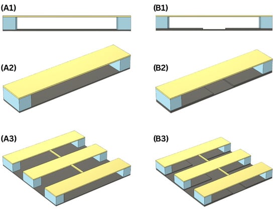
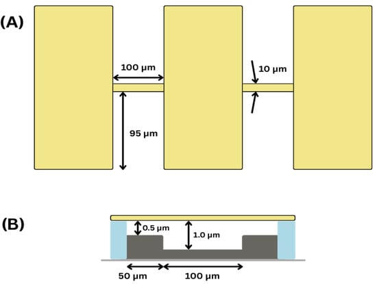
The design in this work utilizes a rectangular-based membrane as the vibrating element when exposed to sound waves. Design characteristics are based on two elements: resonator coupling and the stepped cavity. The purpose is to test the effect on the output voltage and on the bandwidth of the microphone, as explained in Figure 1.
Figure 1.
Design elements explored in this work. (A1) Flat-cavity CMUT design. (A2) 3D representation of a flat-cavity CMUT. (A3) 3D representation of a coupled flat-cavity CMUT. (B1) Stepped-cavity CMUT design. (B2) 3D representation of a stepped-cavity CMUT. (B3) 3D representation of a coupled stepped-cavity CMUT.
The goal of the stepped-cavity design is to achieve a larger capacitance since the electrostatic gap is smaller at the edges of the design. The edges of the membrane experience very little displacement, so reducing the thickness of the gap does not restrict the movement of the membrane. Coupling between the resonators not only increases the capacitance of the microphone but also its bandwidth without any large effect on the natural frequency compared to a single resonator.
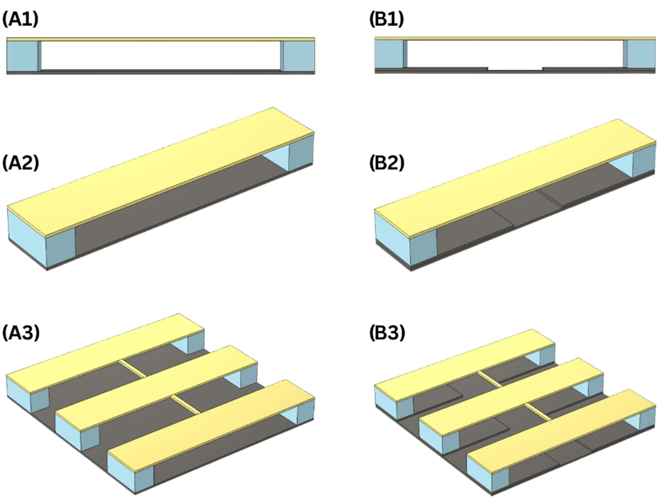
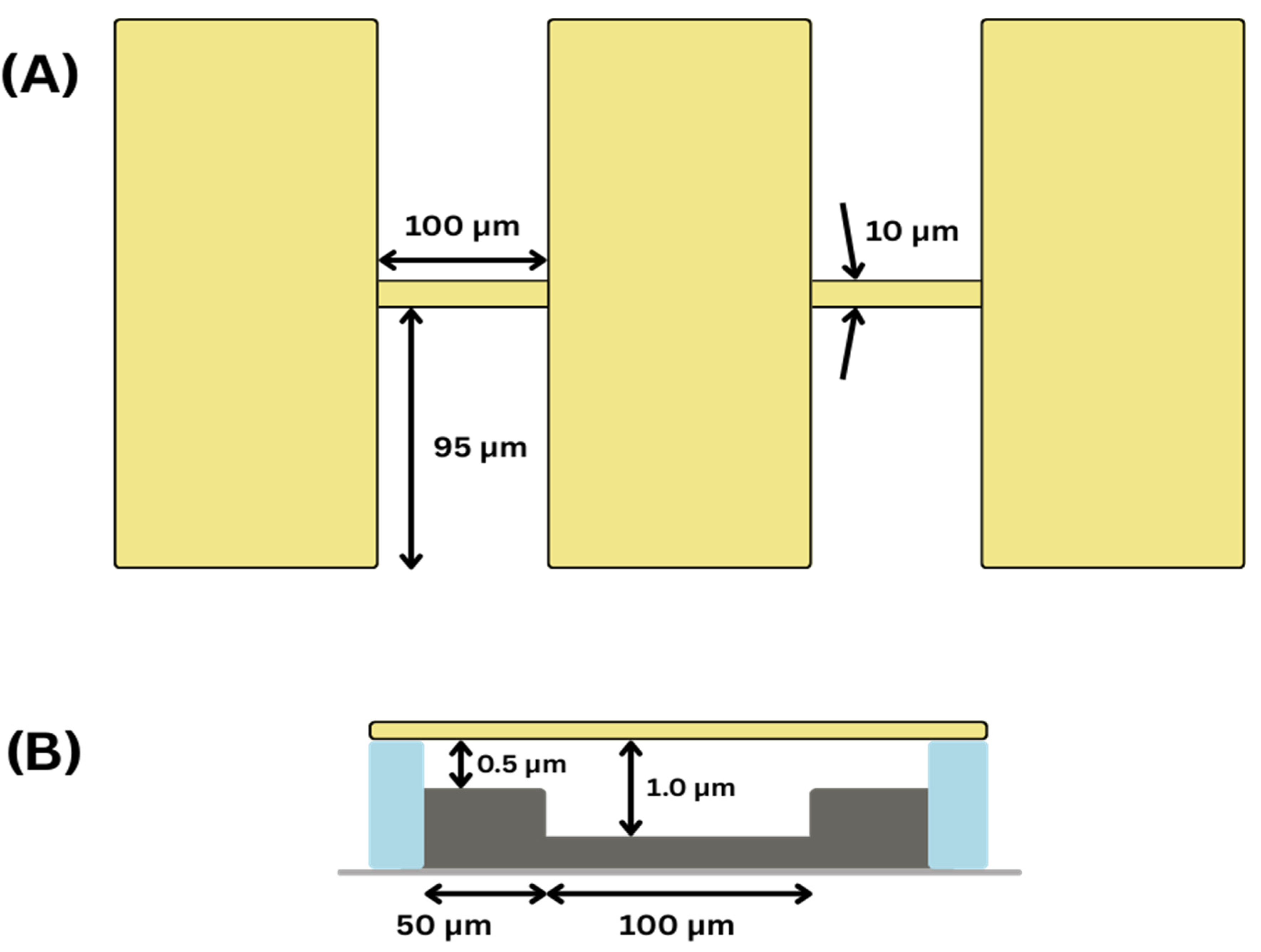
In this study, the rectangular membrane is made from silicon with a thickness of 0.5 µm. The mechanical properties used for silicon are Young’s modulus of 170 Gpa, a density of 2329 kg/m3, and a Poisson’s ratio 0.28. The membrane had a length of 200 µm and a width of 100 µm. These design parameters are chosen as initial values to evaluate the stepped-cavity concept. The reduced gap region is introduced to enhance capacitance, while the larger gap preserves structural stiffness and resonance characteristics. The design will be further optimized based on experimentally validated models in future work.
When fixed at its sides, the resonator has a natural frequency of 100 kHz. The resonator was employed in a three-coupled resonator configuration with a stepped-cavity design, as shown in Figure 2.
Figure 2.
(A) Top view of the three-coupled resonator design. (B) Side view of the stepped-cavity design for each resonator used in this work.
In order to see the effect of design variations, the effect of the length of the central resonator on the frequency response was also studied. All comparisons in this study were made on the same mesh.
2.2. (B) Modeling Approach: Electromechanical Modeling of the CMUT: Pre-Stressed RC Configuration
COMSOL Multiphysics 6.2 was the main tool in this work. The eigenfrequency study was performed to determine the natural frequency of the microphones and test the performance of each design.
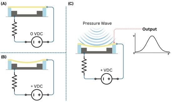
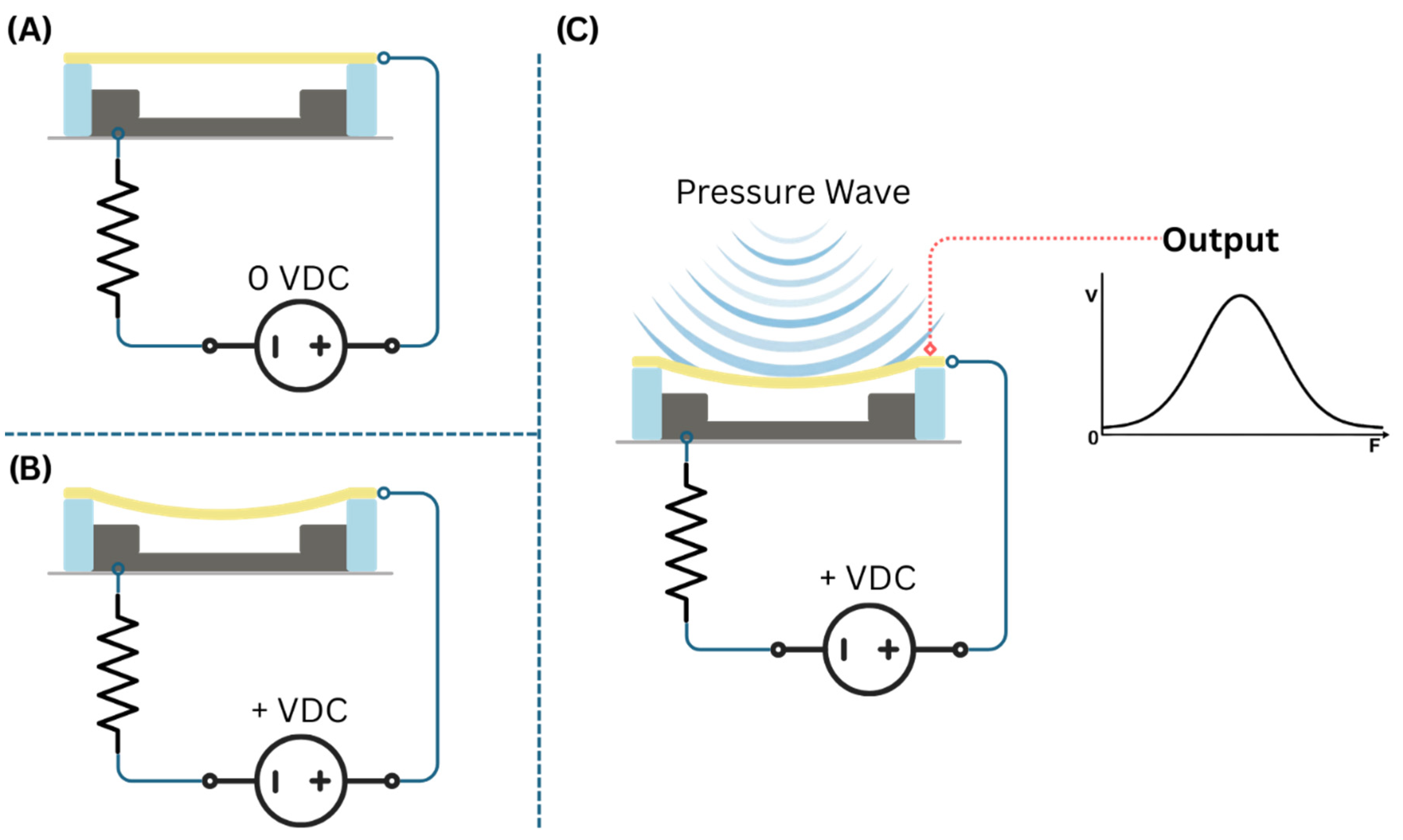
The CMUT will operate as a capacitor within a series RC circuit. The voltage source of the circuit is a DC voltage that charges the capacitor and pre-stresses the membrane. When the sound waves exert pressure on the membrane, an AC voltage is generated across the CMUT (the capacitor) based on the amplitude of the vibrations caused by the sound waves. The sound wave in the simulations has a sound pressure of 0.1 Pa and is modeled as harmonic perturbations. A schematic of the modeling setup is shown in Figure 3.
Figure 3.
Modeling setup used in COMSOL Multiphysics showing the RC circuit formed using the stepped-cavity CMUT as the capacitor in the circuit. (A) RC circuit without voltage application. (B) The deflection of the membrane due to DC pre-stressing to charge the CMUT. (C) The application of pressure (acoustic) waves on a pre-stressed CMUT and the absolute amplitude of the voltage across it.
The value of the voltage of the DC voltage source was chosen as the nearest integer value before the pull-in event. We used the pull-in voltage as the criterion for selecting the pre-stressing voltage, thereby providing a consistent framework for future development of this concept; for the basic design, the DC voltage was 3 V. The resistor value was 1 kΩ. The damping was modeled using an isotropic loss factor of 0.01. The frequency sweep had a 100 Hz resolution. These parameters were selected to provide a consistent comparison framework and to simulate acoustic emission conditions within a reasonable computational cost, while maintaining signal levels comparable to the detection thresholds reported for sensors used in additive manufacturing applications [2].
COMSOL Multiphysics was also used at this stage by performing a frequency domain perturbation study on electrochemical MEMS problems using the electromechanical forces interface that couples electrostatics and solid mechanics physics. This work was performed on a desktop with an Intel 12900K processor and 32 GB of RAM.
3. Results
3.1. Effect of Resonator Coupling on Natural Frequencies
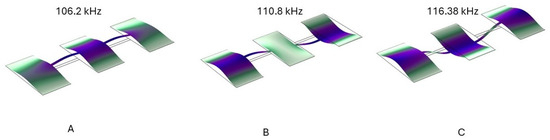
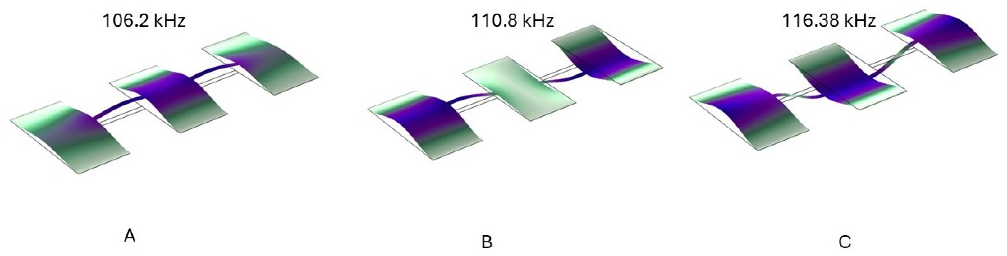
To investigate the influence of mechanical coupling on the dynamic behavior of the device, the eigenfrequency analysis of the proposed coupled-resonator CMUT was performed. The first three mode shapes are presented in Figure 4. A mesh independence study was conducted using COMSOL automatic mesh settings, and the results are shown in Table 1.
Figure 4.
Mode shapes of the proposed coupled CMUT design: (A) first mode (106.2 kHz), (B) second mode (110.8 kHz), and (C) third mode (116.38 kHz).
Table 1.
Mesh independence study for eigenvalue analysis of the coupled CMUT design using COMSOL automatic meshing.
As shown in Figure 4, the first three resonance frequencies are closely spaced. This modal clustering is a direct consequence of the mechanical coupling between adjacent resonators and is advantageous for bandwidth enhancement. The proximity of these modes enables a broadened effective frequency response, thereby improving the operational bandwidth of the microphone.
3.2. Comparison of CMUT Resonator Configurations
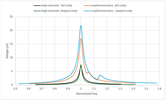
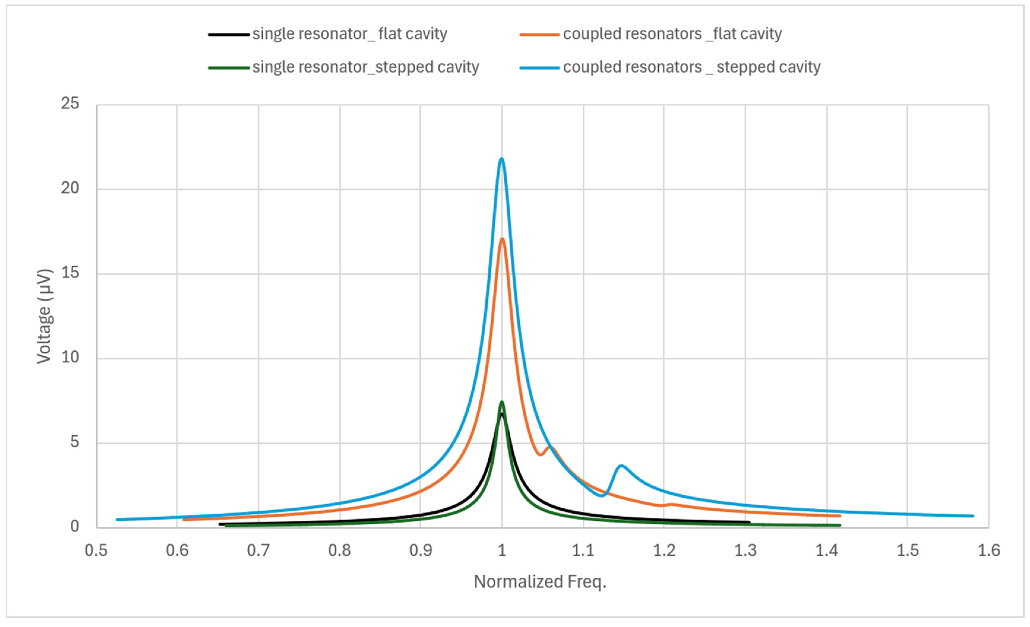
Figure 5 presents the normalized frequency response of four CMUT configurations: single-resonator and coupled-resonator designs, each implemented with flat and stepped cavities. For consistency, the flat-cavity thickness was fixed at 1.0 µm. The comparison highlights the influence of resonator coupling and cavity geometry on the voltage response near resonance.
Figure 5.
Normalized frequency response comparison of four CMUT configurations: single-resonator and coupled-resonator designs with flat and stepped cavities.
Figure 5 quantitatively demonstrates the performance enhancement achieved through resonator coupling and stepped-cavity implementation. The single-resonator flat-cavity configuration exhibits a peak voltage of approximately 6.75 µV at resonance. Introducing a stepped cavity slightly improves the response, yielding a comparable peak of about 7 µV.
In contrast, the coupled-resonator flat-cavity design shows a substantial increase in peak magnitude to approximately 16.5 µV, representing more than a twofold improvement compared to the single-resonator case. The highest performance is achieved with the coupled stepped-cavity configuration, which reaches a peak voltage of approximately 21.5 µV, corresponding to nearly a threefold enhancement over the baseline single-resonator flat-cavity design.
Additionally, the coupled configurations exhibit a wider effective response region around the normalized resonance frequency due to modal interaction, contributing to bandwidth expansion. These results confirm that resonator coupling significantly enhances sensitivity, while the stepped-cavity geometry provides further amplification. The combination of both design strategies yields a synergistic improvement in both voltage output and operational bandwidth, making it the most advantageous configuration among the four investigated cases.
3.3. Finer Mesh Comparison Between Single and Coupled Resonators
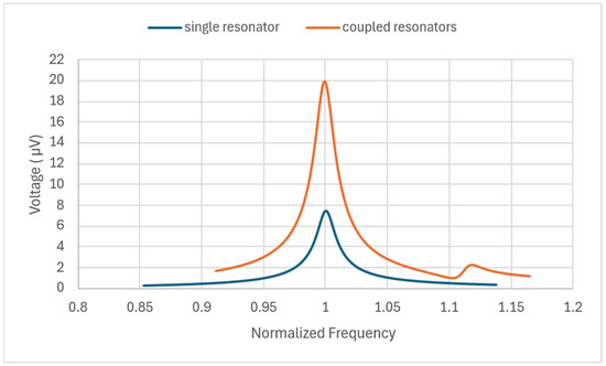
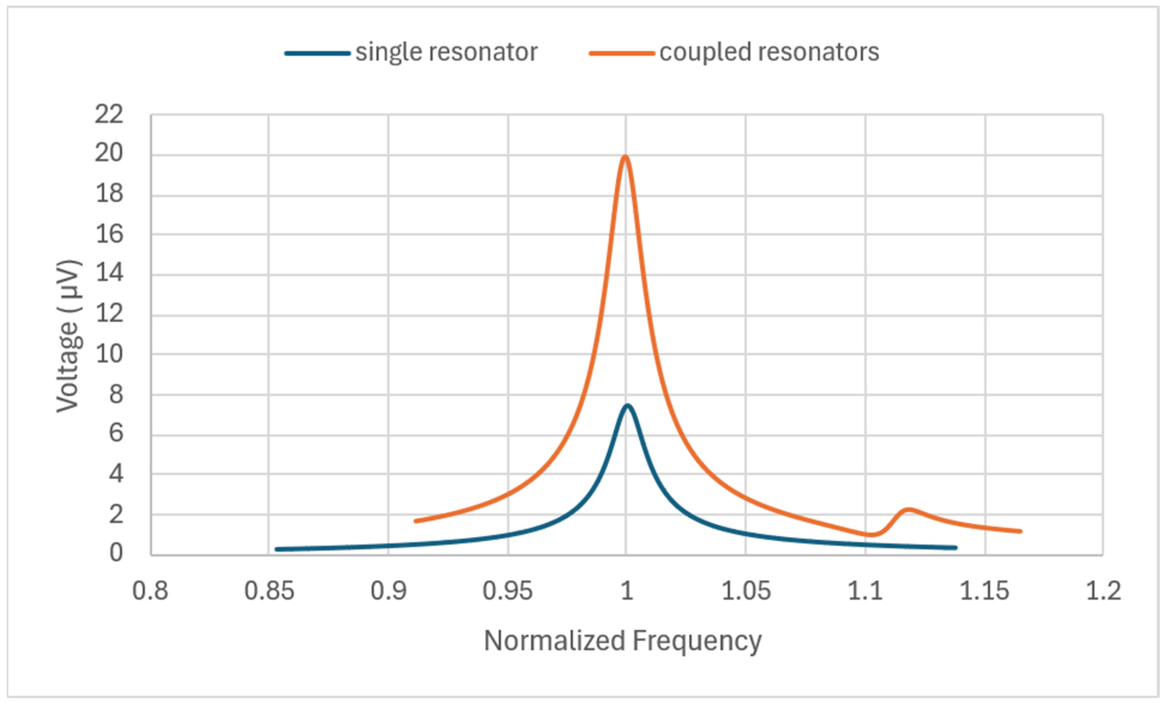
To verify the numerical stability and accuracy of the simulations, the frequency response analysis was repeated in COMSOL using an automatically generated finer mesh for both the single- and coupled-resonator designs with stepped-cavity configurations. The normalized frequency results are presented in Figure 6.
Figure 6.
Normalized frequency response obtained using a finer mesh for stepped-cavity single and coupled CMUT resonators.
As shown in Figure 6, the overall trend remains consistent with the results presented in Figure 5. The coupled-resonator configuration continues to exhibit a significantly higher peak voltage compared to the single-resonator design. With the finer mesh, the peak voltage of the coupled resonator is approximately 20 µV, compared to about 21.5 µV obtained with the standard mesh. This minor variation is attributed to the improved spatial resolution of the structural and electrostatic fields.
Importantly, the relative enhancement between single and coupled resonators remains unchanged, confirming that the observed performance improvement is not a mesh-dependent artifact. The preservation of both the resonance frequency location and the amplitude enhancement trend demonstrates that the results are mesh-convergent and numerically reliable.
3.4. Effect of the Dimensions of the Central Resonator
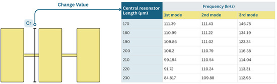
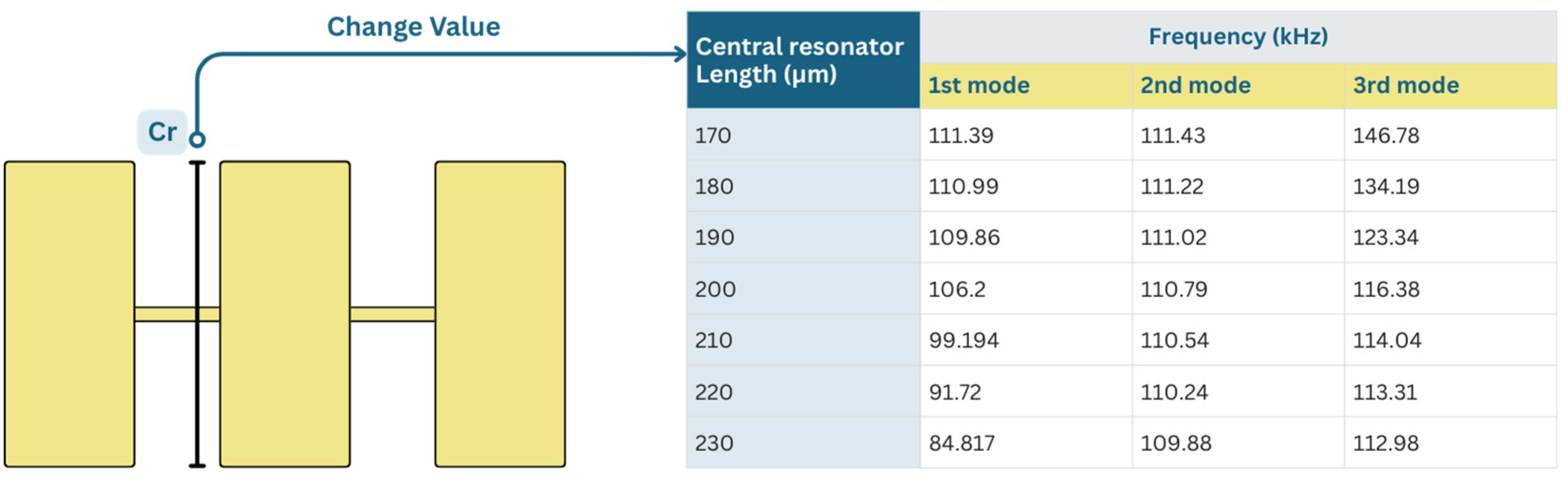
The effect of varying the length of the central resonator on the modal frequencies of the coupled CMUT MEMS microphone is illustrated in Figure 7. As the central resonator length increases from 170 µm to 230 µm, a significant shift in the modal frequencies is observed, particularly in the first and third modes.
Figure 7.
Effect of central resonator length (170–230 µm) on the first three modal frequencies of the stepped-cavity coupled CMUT MEMS microphone. The first and third modes exhibit a strong inverse relationship with resonator length, while the second mode remains nearly constant, indicating different modal sensitivities to structural scaling.
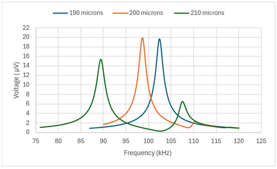
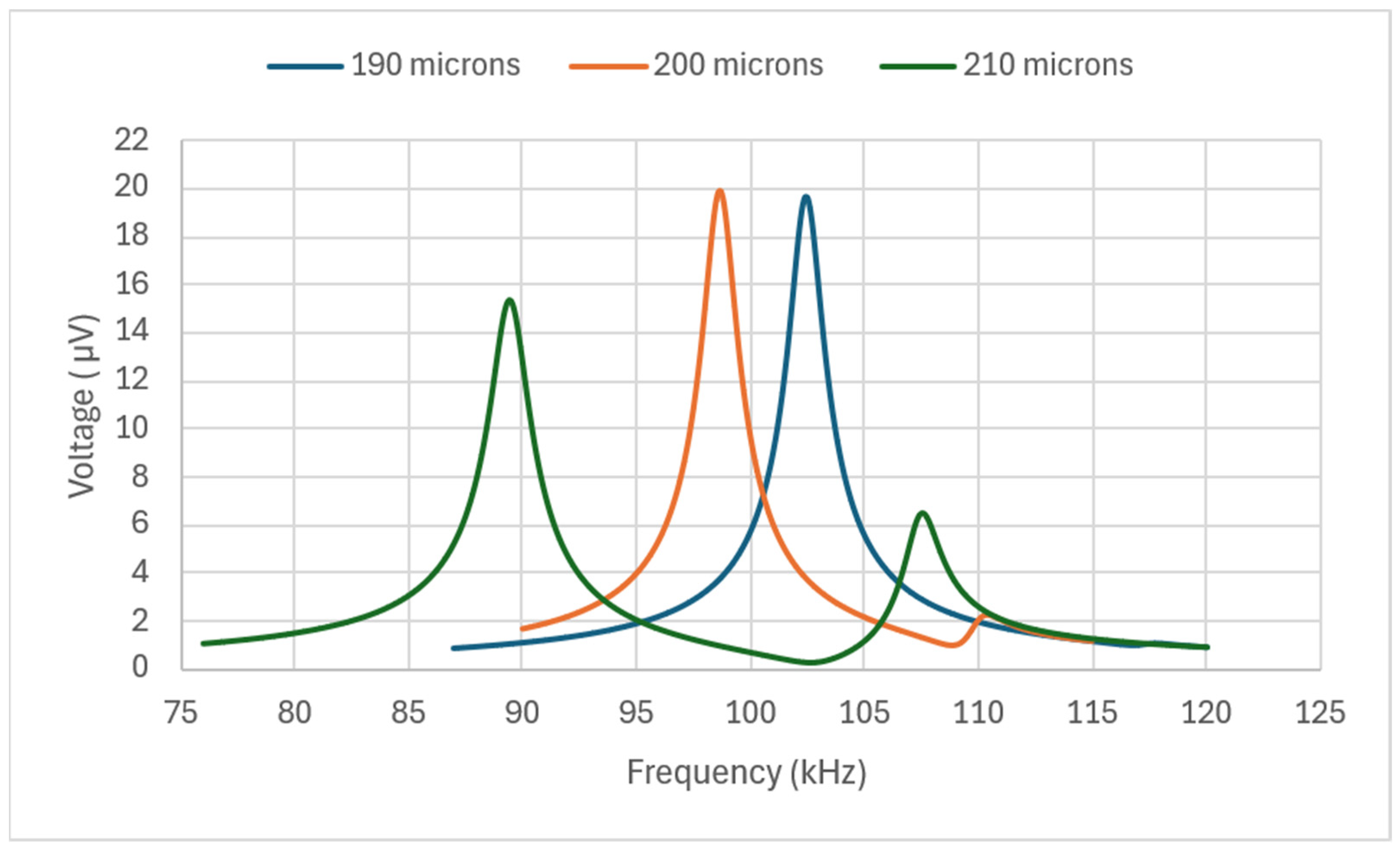
To further illustrate the dynamic behavior, the frequency responses (using a finer mesh for improved accuracy) of the 190 µm, 200 µm, and 210 µm designs are presented in Figure 8. The resonance peaks clearly shift toward lower frequencies as the central resonator length increases. The 190 µm design exhibits a dominant peak near ~102.5 kHz, while the 200 µm and 210 µm designs shift toward ~98.5 kHz and ~89 kHz, respectively. Additionally, changes in peak amplitude and bandwidth can be observed, reflecting variations in modal coupling and effective stiffness. These results confirm that the central resonator length provides an effective tuning parameter for controlling the primary resonance frequency without significantly disturbing the second mode, enabling flexible frequency tailoring of the stepped-cavity coupled CMUT microphone.
Figure 8.
Frequency responses of the stepped-cavity coupled CMUT MEMS microphone for central resonator lengths of 190 µm, 200 µm, and 210 µm (finer mesh simulation). Increasing the central resonator length shifts the dominant resonance peak toward lower frequencies, demonstrating effective mechanical tuning of the device.
4. Discussion
The performance enhancement observed in this work stems from the combined effects of resonator coupling and stepped-cavity geometry. While both design modifications increase capacitance, they influence device behavior through different physical mechanisms.
The stepped cavity improves electromechanical sensitivity by reducing the electrostatic gap at the membrane edges, where displacement is minimal. This increases capacitance without significantly altering structural stiffness, leading to higher output voltage while preserving resonance characteristics. In contrast, mechanical coupling primarily affects the dynamic response. The interaction between adjacent resonators produces closely spaced modes, resulting in a broader effective bandwidth and higher voltage response due to increased vibrating area and modal interaction.
Adjusting the length of the central resonator provides an effective tuning mechanism. Increasing its length lowers the primary resonance frequency while minimally affecting the intermediate mode, indicating that different modes are governed by different stiffness and coupling contributions. The emergence of secondary peaks in longer configurations suggests the possibility of multi-band operation, which could be advantageous for broadband AE detection.
Once this design is fabricated and the model is experimentally validated, several parameters will be evaluated, including SNR, residual stresses, crosstalk, and uncertainty quantification, as these cannot be fully captured within the current simulation framework. Additionally, fabrication tolerances, thermal effects, and noise sources are expected to influence device performance and will be systematically investigated in future experimental studies.
Overall, the coupled stepped-cavity architecture offers a practical strategy to simultaneously enhance sensitivity and bandwidth while maintaining geometric scalability. These characteristics make the proposed design particularly suitable for compact and distributed AE monitoring systems in AM environments.
5. Conclusions
This work presented a finite element study that is focused on developing a coupled-resonator CMUT that can have enhanced performance in terms of output voltage and frequency bandwidth while remaining within the same desired frequencies.
This work provides proof of concept for a MEMS microphone that can be used for the detection of AE for applications in areas such as in situ diagnosis of metal AM and structural health monitoring.
Future work includes the fabrication and testing of MEMS microphones based on this design methodology, developing experimentally verified models that can be used to further design exploration and optimization.
Author Contributions
Conceptualization, S.M. and F.A.; methodology, S.M. and F.A.; software, S.M.; validation, S.M.; formal analysis, S.M. and F.A.; investigation, S.M. and F.A.; resources, S.M. and M.O.; data curation, S.M.; writing-original draft preparation, S.M., M.O., M.A.F. and F.A.; writing-review and editing, S.M., M.O. and F.A.; visualization, M.A.F.; supervision, F.A.; project administration, F.A.; funding acquisition, F.A. All authors have read and agreed to the published version of the manuscript.
Funding
This work was funded by the United States Department of Energy, grant # DE-SC0025550.
Data Availability Statement
The original contributions presented in this study are included in the article.
Conflicts of Interest
The authors declare no conflict of interest.
References
- Strantza, M.; Van Hemelrijck, D.; Guillaume, P.; Aggelis, D.G. Acoustic emission monitoring of crack propagation in additively manufactured and conventional titanium components. Mech. Res. Commun. 2017, 84, 8–13. [Google Scholar] [CrossRef] [Scilit]
- Prem, P.R.; Sanker, A.P.; Sebastian, S.; Kaliyavaradhan, S.K. A review on application of acoustic emission testing during additive manufacturing. J. Nondestruct. Eval. 2023, 42, 96. [Google Scholar] [CrossRef] [Scilit]
- Vidya Sagar, R.; Basu, D.J. Damage assessment of reinforced concrete structures under elevated-amplitude cyclic loading using sentry values based on acoustic emission testing. Nondestruct. Test. Eval. 2023, 38, 612–630. [Google Scholar] [CrossRef] [Scilit]
- Kannivel, S.; Vellayaraj, A.; Kolimi, I.; Thomas, J. Effect of thickness on indentation response and tensile loading behaviour of glass/epoxy laminates under acoustic emission monitoring. Nondestruct. Test. Eval. 2021, 36, 158–175. [Google Scholar] [CrossRef] [Scilit]
- Wu, H.; Yu, Z.; Wang, Y. A new approach for online monitoring of additive manufacturing based on acoustic emission. In International Manufacturing Science and Engineering Conference; American Society of Mechanical Engineers: New York, NY, USA, 2016; Volume 49910, p. V003T08A013. [Google Scholar]
- Shi, Z.; Li, J.; Ranjith, P.G.; Lin, H.; Liu, T.; Li, K.; Han, D. Laboratory study on acoustic emission signals and damage mechanism of rock with thermal storage potential under fatigue loading. J. Energy Storage 2024, 103, 114414. [Google Scholar] [CrossRef] [Scilit]
- Grosse, C.; Linzer, L. Signal-Based AE Analysis. In Acoustic Emission Testing; Grosse, C., Ohtsu, M., Eds.; Springer: Berlin/Heidelberg, Germany, 2008. [Google Scholar] [CrossRef] [Scilit]
- Huang, S.F.; Li, M.M.; Xu, D.Y.; Zhou, M.J.; Xie, S.H.; Cheng, X. Investigation on a kind of embedded ae sensor for concrete health monitoring. Res. Nondestruct. Eval. 2013, 24, 202–210. [Google Scholar] [CrossRef] [Scilit]
- Hassan, F.; Mahmood, A.K.B.; Yahya, N.; Saboor, A.; Abbas, M.Z.; Khan, Z.; Rimsan, M. State-of-the-art review on the acoustic emission source localization techniques. IEEE Access 2021, 9, 101246–101266. [Google Scholar] [CrossRef] [Scilit]
- Cao, T.; Hu, T.; Zhao, Y. Research status and development trend of MEMS switches: A review. Micromachines 2020, 11, 694. [Google Scholar] [CrossRef] [Scilit]
- Lucyszyn, S.; Pranonsatit, S.; Choi, J.Y.; Moseley, R.W.; Yeatman, E.M.; Holmes, A.S. Novel rf mems switches. In 2007 Asia-Pacific Microwave Conference; IEEE: Piscataway, NJ, USA, 2007; pp. 1–4. [Google Scholar]
- Mohaidat, S.; Okour, M.; Alsaleem, F. A sensing material-free and simple readout MEMS sensor for detecting helium. J. Micromech. Microeng. 2025, 35, 025013. [Google Scholar] [CrossRef] [Scilit]
- Mohaidat, S.; Nikfarjam, H.; Okour, M.; Megdadi, M.; Al Fayad, M.; Pourkamali, S.; Alsaleem, F. A large-stroke thermomechanical MEMS actuator with lever amplification for helium detection. Sens. Actuators A Phys. 2025, 395, 117091. [Google Scholar] [CrossRef] [Scilit]
- Bogue, R. MEMS sensors: Past, present and future. Sens. Rev. 2007, 27, 7–13. [Google Scholar] [CrossRef] [Scilit]
- Okour, M.; Nikfarjam, H.; Al Fayad, M.; Tafti, F.F.; Takallou, M.A.; Pipinos, I.I.; Pourkamali, S.; Myers, S.; Alsaleem, F. A MEMS network operating as a reservoir computer to classify peripheral artery disease signal from a healthy signal. Sens. Actuators A Phys. 2025, 385, 116318. [Google Scholar] [CrossRef] [Scilit]
- Nikfarjam, H.; Megdadi, M.; Okour, M.; Pourkamali, S.; Alsaleem, F. Energy efficient integrated MEMS neural network for simultaneous sensing and computing. Commun. Eng. 2023, 2, 19. [Google Scholar] [CrossRef] [Scilit]
- Phillips, E. Structural Health Monitoring: The Use of Acoustic Emission to Optimize the FDM Additive Manufacturing Process. Master’s Thesis, Prairie View A&M University, Prairie View, TX, USA, 2023. [Google Scholar]
- Muralt, P. Recent progress in materials issues for piezoelectric MEMS. J. Am. Ceram. Soc. 2008, 91, 1385–1396. [Google Scholar] [CrossRef] [Scilit]
- Giurgiutiu, V. Structural Health Monitoring with Piezoelectric Wafer Active Sensors; Academic Press: Cambridge, MA, USA, 2014. [Google Scholar]
- Wang, L.; Wang, C.; Wang, Y.; Quan, A.; Keshavarz, M.; Madeira, B.P.; Zhang, H.; Wang, C.; Kraft, M. A review on coupled bulk acoustic wave MEMS resonators. Sensors 2022, 22, 3857. [Google Scholar] [CrossRef] [Scilit] [PubMed]
- Wang, Q.; Zhang, Y.; Cheng, S.; Wang, X.; Wu, S.; Liu, X. MEMS acoustic sensors: Charting the path from research to real-world applications. Micromachines 2024, 16, 43. [Google Scholar] [CrossRef] [Scilit]
- Zhu, J.; Liu, X.; Shi, Q.; He, T.; Sun, Z.; Guo, X.; Liu, W.; Sulaiman, O.B.; Dong, B.; Lee, C. Development trends and perspectives of future sensors and MEMS/NEMS. Micromachines 2019, 11, 7. [Google Scholar] [CrossRef] [Scilit]
- Boubenia, R.; Le Moal, P.; Bourbon, G.; Ramasso, E.; Joseph, E. CMUT-based sensor for acoustic emission application: Experimental and theoretical contributions to sensitivity optimization. Sensors 2021, 21, 2042. [Google Scholar] [CrossRef] [Scilit] [PubMed]
- Selvam, K.; Saeidi, N.; Schwarzmann, Y.; Wiemer, M.; Kuhn, H. Investigation of Capacitive Micromachined Ultrasound Transducer for NDT and material inspection in metals and alloys. In 2025 IEEE International Instrumentation and Measurement Technology Conference (I2MTC); IEEE: Piscataway, NJ, USA, 2025; pp. 1–5. [Google Scholar]
- Wodnicki, R.; Foiret, J.; Liu, B.; Lu, N.; Sun, X.; Zhang, J.; Kang, H.; Fu, L.; Notard, C.; Legros, M.; et al. Handheld Large 2D Array with Azimuthal Planewave and Row-Multiplexed Elevation Beamforming Enabled by local ASIC Electronics. IEEE Trans. Ultrason. Ferroelectr. Freq. Control 2025, 72, 962–978. [Google Scholar] [CrossRef] [Scilit]
- Zhang, S.; Wang, A.; Cui, S.; Wang, Z.; Pan, S.; Wang, R.; Zhang, W.; Yilmaz, M. Design and Acoustic Performance Study of Capacitive Acoustic Emission Sensors Based on MEMS Technology. IEEE Sens. J. 2025, 25, 29422–29436. [Google Scholar] [CrossRef] [Scilit]
- He, C.; Luo, M.; Chai, H.; Wang, H.; Zhang, G.; Wang, R.; Cui, J.; Yang, Y.; Zhang, W.; Jia, L. Design and Evaluation of a Capacitive Micromachined Ultrasonic Transducer (CMUT) Linear Array System for Thickness Measurement of Marine Structures Under Varying Environmental Conditions. Micromachines 2025, 16, 898. [Google Scholar] [CrossRef] [Scilit] [PubMed]

Disclaimer/Publisher’s Note: The statements, opinions and data contained in all publications are solely those of the individual author(s) and contributor(s) and not of MDPI and/or the editor(s). MDPI and/or the editor(s) disclaim responsibility for any injury to people or property resulting from any ideas, methods, instructions or products referred to in the content. |
© 2026 by the authors. Licensee MDPI, Basel, Switzerland. This article is an open access article distributed under the terms and conditions of the Creative Commons Attribution (CC BY) license.