


Abstract
Keeping the battery temperature below a reasonable limit of 50 °C is a primary objective of battery thermal management systems (BTMSs). Accordingly, the battery available operating time (BAOT) can be defined as the time required for the battery maximum temperature to reach 50 °C, which could be adopted as a key indicator for safe and efficient operation. BAOT can be improved through different BTMS configurations. This work focuses on passive solutions, aiming to increase BAOT without requiring pumping power. The study numerically investigates the combined use of phase change materials (PCMs) and fins to evaluate their effectiveness in terms of time percentage improvement (TPI). A preliminary analysis is conducted to assess the need for PCMs and fins at three discharge rates, namely 1C, 3C, and 5C. The results indicate that PCMs are required under all operating conditions, while the use of fins is not always advantageous; in particular, at 1C, fins lead to a reduction in BAOT. The analysis then focuses on the 3C and 5C cases, where topology-optimized fins are employed to dump temperatures under these stress conditions. Three fin arc lengths (ψfin) and eight diffusion coefficients (Rf) are examined. The optimized fin configurations increase BAOT, achieving maximum TPIs of 10.61% and 7.69% for the 3C and 5C cases, respectively, both corresponding to ψfin = 2.75 mm and Rf = 0.10 mm. At 5C, BAOT is limited to only a few seconds; therefore, configurations with PCMs arranged in series are also analyzed using different combinations of four selected PCMs. When coupled with optimized fins, the PCM-in-series solutions yield further improvements, with maximum TPIs of 22.92% for 3C and 62.50% for 5C compared to the single-PCM configuration coupled with optimized fins. The results also show that the optimal diffusion coefficient and PCM arrangement strongly depend on the discharge rate.
1. Introduction
The intensification of global environmental changes resulting from the extensive use of fossil fuels in industrial processes and internal combustion engine vehicles, combined with the continuously growing global energy demand, has drawn increasing attention to the utilization of Lithium-ion (Li-ion) batteries [1]. Li-ion batteries currently represent the dominant energy storage technology in electric vehicles (EVs), stationary energy storage systems, and portable electronic devices [2], primarily owing to their high energy density, long cycle life, and negligible memory effect [3]. However, the demand for faster charging and discharging rates inevitably leads to a rapid increase in battery temperature, posing a serious threat to both user safety and battery lifetime. For Li-ion batteries, there exists a critical temperature threshold of approximately 50 °C [4], beyond which thermal runaway may occur [5], caused by exothermic thermochemical reactions within the cell.
To ensure both safety and optimal performance, efficient Battery Thermal Management Systems (BTMSs) are required. Various cooling strategies have been proposed to maintain the cell temperature below the critical limit, including air cooling (natural or forced convection), direct and indirect liquid cooling, and phase change material (PCM)-based cooling systems. BTMSs can be broadly classified into passive and active systems. Passive systems—such as natural air convection and PCM thermal management—do not require external power input and are generally more cost-effective to implement. However, their heat dissipation capability is limited. In contrast, active systems—such as liquid cooling—offer superior heat removal performance but involve higher costs and greater design complexity [6]. Among passive methods, PCM-based ones are particularly attractive because they dissipate heat through the latent heat absorbed during the phase change process, maintaining their temperature within a narrow range without significant thermal rise. Different types of PCMs—such as organic oils, hydrated salts, and paraffins [7]—have been investigated, each characterized by specific thermophysical properties, particularly latent heat and melting temperature, which are crucial for thermal performance [8].
Recently, topology optimization (TO) techniques have been increasingly employed in the design of thermal management systems to achieve optimized geometries that enhance thermal efficiency while minimizing material usage. In particular, TO has been applied to the optimization of cold plate channel configurations, improving both thermal and fluid dynamic performance by reducing the pressure drop and consequently lowering the required pumping power [9].
In order to reduce the energy required to maintain the batteries in temperature, this study aims to evaluate the effectiveness of a passive cooling strategy based on the use of PCMs. The system performance is assessed by measuring the time required for the maximum battery temperature to reach a prescribed safety limit of 50 °C, defined as the battery available operating time (BAOT). This parameter is essential for evaluating the effectiveness of various BTMSs under the same operating conditions, ultimately facilitating a dimensionless comparison based on operating times. Initially, three configurations are compared. The first configuration, referred to as the “Baseline”, considers a battery without PCMs cooled only by air. Next, the “Only PCM”, evaluates the thermal response of the battery surrounded solely by PCM. Finally, the “Rectangular fins” investigates the inclusion of rectangular aluminum fins embedded within the PCM domain and in direct contact with the battery surface.
Following this preliminary analysis, a topology-optimized fin configuration is introduced, evaluating the effect of the change in diffusion coefficient and fin arc length, to further enhance heat dissipation within the PCM domain and thereby extend the BAOT. Finally, an additional cooling strategy based on multiple PCM layers arranged in series is proposed and evaluated, with the objective of further increasing the BAOT, particularly under the high heat generation conditions associated with the 5C discharge rate.
2. Materials and Methods
This section presents the geometric configurations of the battery, PCM, and fins. Furthermore, it details the mathematical formulations for battery heat generation, followed by a grid independence analysis and a model validation. It then describes two configurations: the “Only PCM” case, with the PCM surrounding the battery, and the “Rectangular fins” case, where the rectangular fins are inserted in the PCM. Finally, the PCM thermal model and the topology optimization equations are presented, including the boundary conditions, constraints, objective function, and optimized results.
2.1. Battery Geometrical and Thermal Model
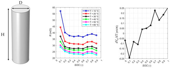
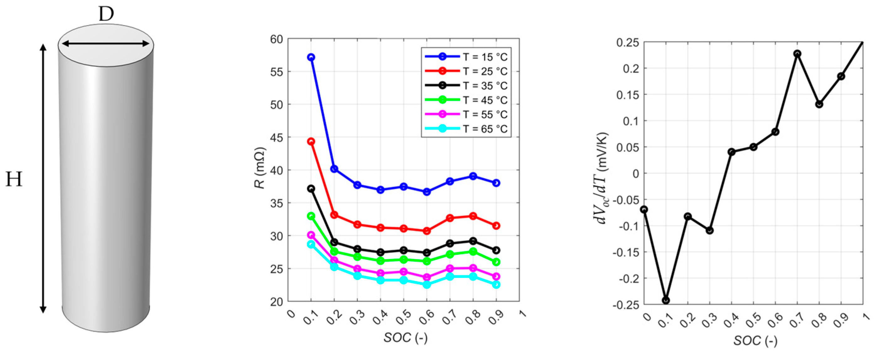
The Li-ion battery investigated in this study is a 21,700 cylindrical cell. Its geometrical parameters consist of a diameter (D) of 21 mm and a height (H) of 71 mm. The nominal voltage (Vₙ) and capacity (C) are 3.6 V and 4.9 Ah, respectively. The thermophysical properties include a density (ρ) of 2846 kg m−3, anisotropic thermal conductivity (k) of 0.9 W m−1 K−1 in the radial direction and 24.2 W m−1 K−1 in the axial direction, and a specific heat capacity (c) of 885 J kg−1 K−1. All geometrical, electrical, and thermophysical parameters are illustrated in Figure 1 and summarized in Table 1.
Figure 1.
Geometrical battery parameters (left), internal battery resistance (middle), and entropic coefficient (right) trends at different temperatures, both as a function of SoC.
Table 1.
Electrical and thermophysical parameters of the battery.
The thermal model is described by the heat diffusion equation shown in Equation (1):
where T and represent the temperature of the battery and the heat source term, which follows Bernardi’s electro-thermal model [10]. In detail, this model includes two heat source terms, say irreversible heat generation (), from ohmic and polarization losses in the cell materials, and a reversible heat generation (), associated with entropy changes during electrochemical reactions. The former follows Joule’s heating, and it depends on internal resistance (R), current intensity (I)—assumed positive during discharge, and uniform in the battery—and is strongly dependent on State of Charge (SoC) and battery temperature (T). The latter is dependent on the current intensity (I), the temperature (T)—in this case average battery temperature (Tavg) has been considered—and the entropic coefficient (), which explains the dependence of the open voltage circuit (VOC) by the temperature. All the mentioned parameters are explained in Equations (2)–(5):
where t is the time. The battery internal resistance (R) follows the fitted equations explained in Equation (6) derived from experimental campaigns from [11], while the entropic coefficient () trend is obtained by analysis from the experimental results [11] without the evaluation of an equation, and linearly interpolated. Both internal resistance and entropic coefficient trends are shown in Figure 1.
Grid Independence and Battery Validation
A grid independence study is conducted to ensure the accuracy and robustness of the numerical simulations. This analysis verifies that further mesh refinement does not significantly affect the results, confirming the adequacy of the selected grid. To reduce computational costs, all subsequent simulations involving PCMs and fins are carried out using a 2D model. Temperature gradients along the vertical direction (height H in Figure 1) are neglected. This simplification is justified by the anisotropic thermal conductivity of the cell [9], which differs in the radial (r) and axial (z) directions. Since the axial thermal conductivity is higher than the radial one (see Table 1), limited temperature gradients are expected along the vertical direction. Furthermore, the Biot number (Bi)—which represents the ratio between conductive thermal resistance and convective thermal resistance—calculated according to Equation (7), is equal to 0.04 in the axial direction (Biz). As stated in [12], when the Biot number evaluated along a given direction is lower than 0.1, the conductive resistance along that direction is small compared with the convective one, and temperature gradients can therefore be considered negligible. In the present case, the axial Biot number is below this threshold; therefore, temperature gradients along the axial direction can reasonably be neglected, and the thermal behavior can be evaluated only in the radial direction. This simplification may lose validity under conditions characterized by non-uniform cooling or heating along the axial direction, improved convective cooling conditions, larger cell dimensions, or lower thermal conductivity in the axial direction, which may lead to Biz > 0.1. In such cases, a full 3D model would be more appropriate.
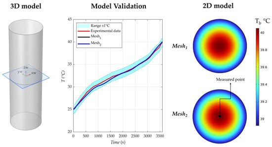
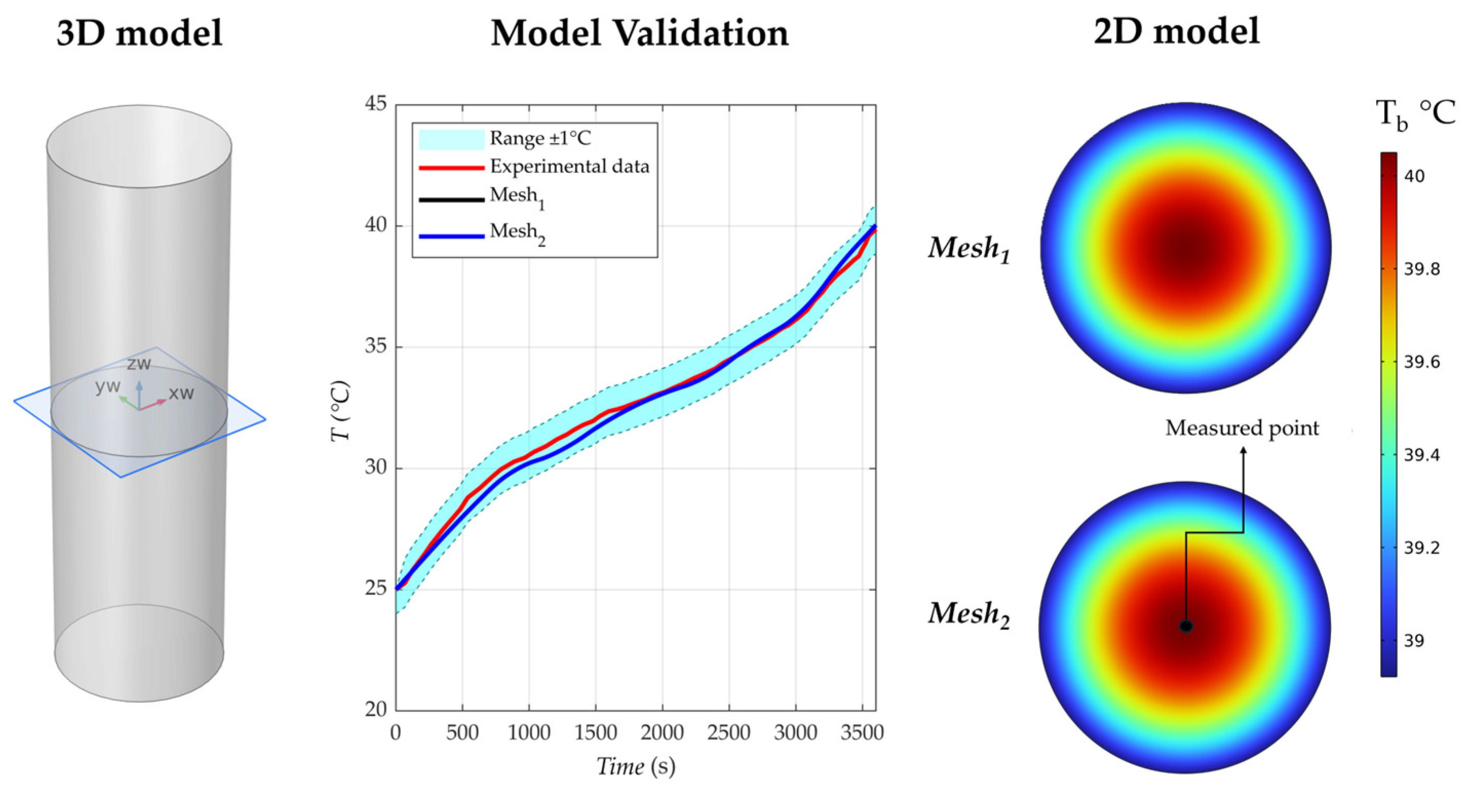
Grid independence and model validation were assessed simultaneously to ensure both numerical accuracy and physical reliability, as shown in Figure 2. Two meshes were tested for the 2D model, referred to as Mesh1 and Mesh2, with 106,768 and 289,966 elements, respectively. The minimum element sizes were 0.09 mm and 4.2 × 10⁻⁴ mm, while the maximum element sizes were 0.1 mm and 0.06 mm. In both cases, the maximum growth rate was set to 1.1, the curvature factor to 0.2, and the resolution of narrow regions to 1. A free triangular meshing scheme was adopted.
Figure 2.
3D model (left), experimental validation [11] with grid consistency (middle), and 2D model (right) temperature fields.
The temperature at the center of the 2D domain was selected as the reference variable. Numerical results obtained with both meshes were compared with the experimental data reported in [11] under the same operating conditions: discharge rate of 1C, ambient temperature (Tamb) of 25 °C, convective heat transfer coefficient (hconv) of 14 W m−2 K−1, and operating time of 3600 s.
The predicted temperatures were nearly identical for the two meshes and showed good agreement with the experimental measurements, which have an uncertainty of ±1 °C. Mesh1 provided results comparable to the finer mesh while significantly reducing computational cost. Therefore, Mesh1 was adopted for all subsequent simulations, and the model can be considered validated.
2.2. Baseline and Rectangular Fins Case with PCM
In the baseline case, heat transfer occurs solely through natural air convection, consistent with the experimental validation previously described.
In the first enhanced configuration, referred to as the “Only PCM” case, a layer of phase change material surrounds the battery and acts as the BTMS. The PCM is introduced to delay the time required for the battery temperature to reach the prescribed limit and so increase the BAOT. However, PCMs typically exhibit low thermal conductivity [13], which limits heat diffusion away from the battery core.
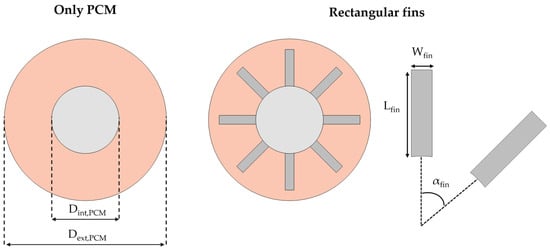
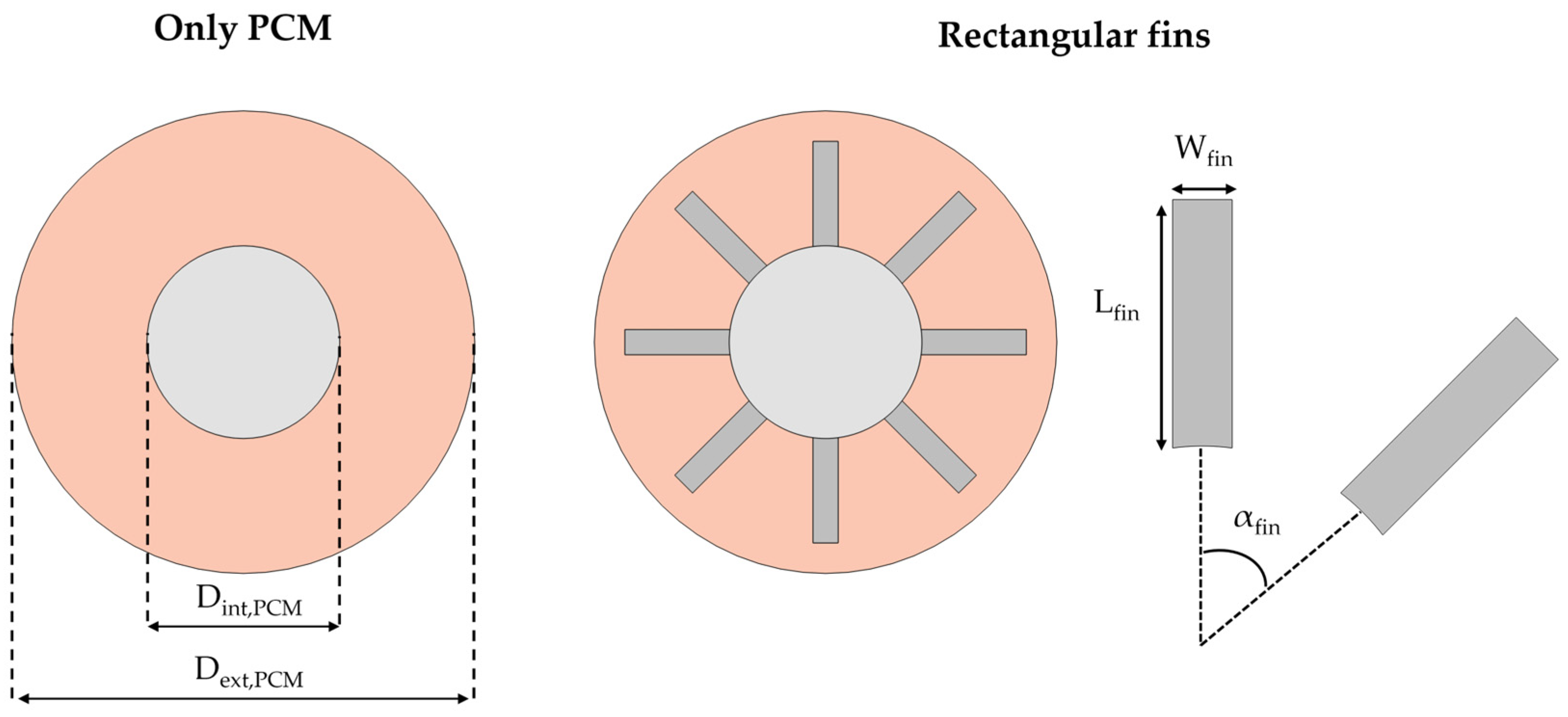
To improve thermal performance, rectangular aluminum fins are added to promote heat transfer within the PCM, accelerate the melting process, and maintain the maximum battery temperature below the critical threshold for a longer period. The “Only PCM” case and the “Rectangular fins” case (battery + PCM + aluminum fins) are illustrated in Figure 3.
Figure 3.
Cases with only PCM (left), and with PCM and rectangular fins (right).
The internal and external PCM diameters, Dint,PCM and Dext,PCM, are 21 mm and 25 mm, respectively. The fin length Lfin, width Wfin, and angular spacing between two adjacent fins αfin are 11.5 mm, 2.75 mm, and 45°, respectively.
To accurately simulate the PCM region, including configurations with embedded fins, a dedicated numerical model is employed to account for the phase change process. This process is described through a key parameter, , referred to as the melt fraction. The melt fraction represents the portion of PCM that has transitioned to the liquid phase at a given temperature relative to the total PCM volume. The melt fraction varies between 0 and 1, corresponding to the fully solid (s) and fully liquid (l) states, respectively. The PCM is considered fully liquid when its temperature exceeds the upper limit of the melting interval, defined as , where . Conversely, the PCM is fully solid when the temperature is below the lower limit of this symmetric interval. This formulation is summarized in Equation (8):
In this equation, Ts and Tl are the temperatures at which the PCM is fully solid and fully liquid, respectively. To obtain a numerical evaluation of the melt fraction, a step function is adopted in order to obtain a smooth transition from solid to liquid phase. In addition to the evaluation of the amount of melted PCM, the melt fraction is used as an interpolation function to evaluate the effective thermophysical properties of the PCM, between the solid and liquid properties, during the melting stage, i.e., to compute the density (ρPCM), specific heat (cPCM) and thermal conductivity (kPCM) of the PCM as shown in Equation (9).
Finally, the PCM within the computational domain is assumed to be a homogeneous and isotropic material, with negligible volume variation during phase transition. The heat transfer is dominated by conduction, while—considering the 2D model—buoyancy-driven natural convection is considered negligible because of the small temperature gradients and scales involved. For these reasons, no mass or momentum conservation equations are solved in the PCM domain, but only the energy conservation equation, as explained in Equation (10):
where the last term represents the latent heat source term to be considered during the phase change process [14]. In this study, PCMs with different properties, listed in Table 2, have been used, i.e., PureTemp-25 by PureTemp LLC (Minneapolis, MN, USA) [15], Climsel-C28 by Climator, (Skövde, Sweden), Crodatherm-32 by Croda International Plc (Snaith, UK), and LA-SA [16].
Table 2.
Thermophysical properties of each used PCM [15].
As previously stated, the fins are made of aluminum. Their thermophysical properties are assumed to be temperature independent. The density (ρfin), specific heat (cfin), and thermal conductivity (kfin) are equal to 2700 kg m−3, 900 J kg−1 K−1 and 237 W m−1 K−1 at 25 °C, respectively. It is important to note that many PCMs may exhibit supercooling effects, resulting in different temperatures for melting and solidification. In the present study, only the melting process was investigated, since the main objective was to evaluate the PCM’s capability to absorb heat generated by the battery during operation. Therefore, supercooling was not explicitly considered, as it does not significantly affect the melting stage. However, in applications involving repeated thermal cycles, the supercooling effect may become relevant during the cooling and recovery phase. In such cases, delayed solidification may prevent the PCM from fully returning to the solid state before the next operating cycle, reducing the amount of latent heat available for subsequent heat absorption. This aspect becomes particularly important in systems operated through temperature-based control strategies, where the battery is restarted once the temperature falls below a prescribed lower threshold. If supercooling is not considered, the battery may resume operation while the PCM is still partially liquid, thus not fully restoring its latent heat storage capacity and reducing the effectiveness of the subsequent thermal management cycle. To accurately represent these conditions, the current model could be extended by introducing different phase-change temperatures for melting and solidification, or by implementing a thermal hysteresis model able to account for the distinct charging and discharging thermal paths of the PCM.
Beyond short-term hysteresis effects, the long-term thermophysical stability of the PCM under repeated cycling must also be considered. In fact, after numerous charge–discharge cycles, phase change material may exhibit performance degradation. Specifically, slight shifts in melting temperature and broadening of the phase-change temperature range can occur. In addition, the supercooling effect may become increasingly pronounced over prolonged cycling. To mitigate these concerns, producers typically specify a cycle life guarantee within which no significant degradation is expected. For instance, the PureTemp datasheet reports stability for up to 10,000 thermal cycles before noticeable degradation occurs.
2.3. Topology Optimization Approach
In both the “Only PCM” and the “Rectangular fins” configurations, the maximum battery temperature does not always remain below the prescribed critical limit. Therefore, an optimization procedure is required. A topology optimization (TO) approach is adopted to design improved fin geometries that enhance heat transfer from the battery to the PCM and promote a more uniform temperature distribution within the PCM domain. A more uniform temperature field leads to a more homogeneous melting process and improved thermal performance. In this study, a density-based topology optimization method is employed.
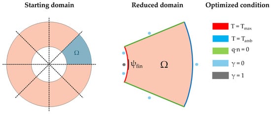
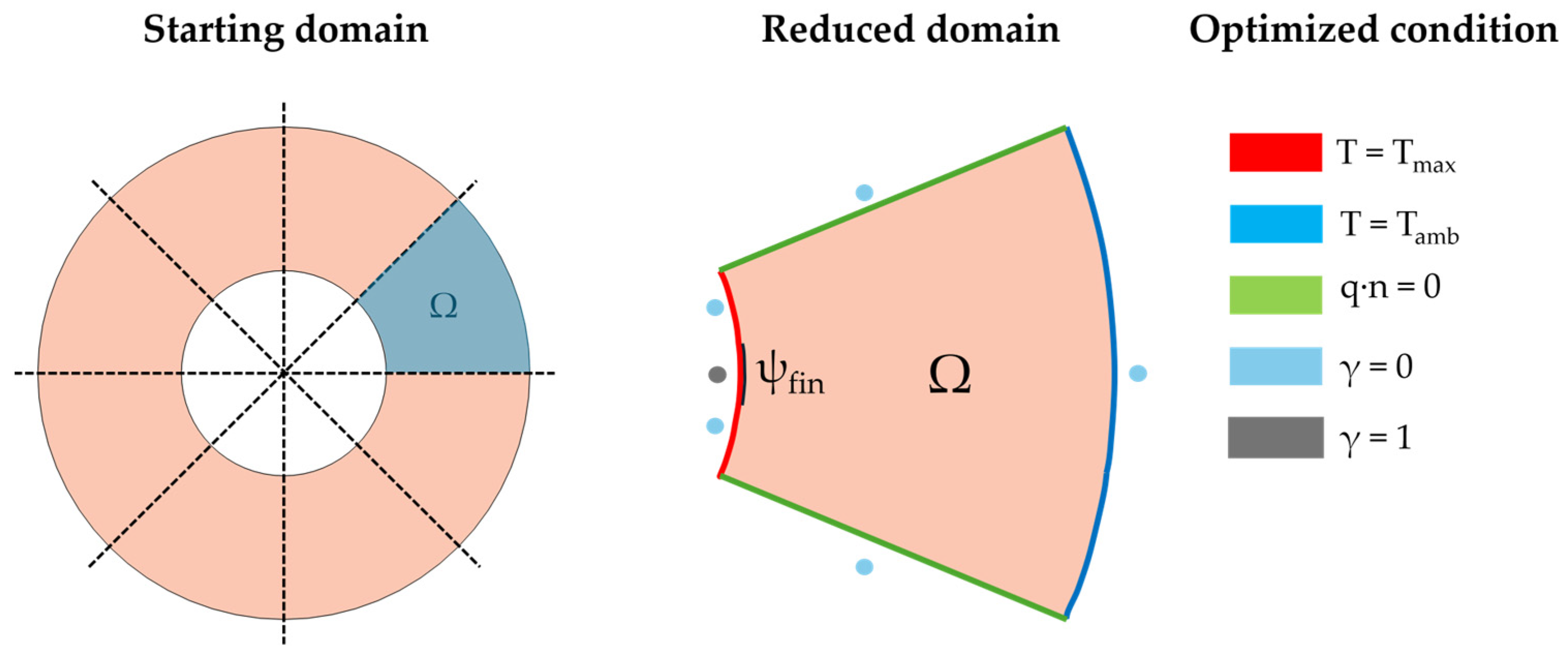
Owing to thermal and geometric symmetry, the computational design domain is reduced to the portion shown in Figure 4, corresponding to one-eighth of the total PCM domain. The key geometric parameter is the fin arc length (ψfin), also illustrated in Figure 4. The fin arc length (ψfin) is defined as the arc of the circumference used to determine the base of the fin. The value in millimeters is given by the distance along the y-axis between the two points. This parameter defines the base of the topology-optimized fins and is assumed equal to the arc length of the rectangular fin configuration to ensure a consistent comparison. In the optimization framework, the arc length region is treated as a solid material zone and imposed as a boundary condition. All remaining external boundaries of the design domain are defined as void regions, preventing the optimized fins from extending to the outer PCM boundary.
Figure 4.
Schematic representation of the design domain and boundary conditions for the topology optimization problem.
Since the objective is to generate optimized fins in direct thermal contact with the battery, a dielectric layer with negligible thermal resistance is assumed at the interface. Under this assumption, heat transfer within the design domain is governed by the heat conduction equation, modified to include the design variable , as follows:
In detail, the density-based approach relies on γ, which varies from 0 to 1, with 0 for PCM and 1 for fins. The effective thermal conductivity (k)—which depends on γ according to the solid isotropic material with penalization (SIMP) scheme [17]—is defined as follows:
where ks is the thermal conductivity of the solid (aluminum), while kPCM is the thermal conductivity of the PCM. η is the penalization factor, assumed equal to 4 [17]. To avoid intermediate values of γ, the Helmholtz filter and hyperbolic tangent projection [18] are applied to the design variable, as follows:
where Rf, and are the diffusion coefficient for the Helmholtz equation [18], the filtered design variable, and the initial design variable value, respectively. Looking at Equation (14), is the projection point while is the projection slope, set equal to 0.5 and 8, respectively. The topology optimization problem is assessed with the method of moving asymptotes (MMA), which allows one to update the values of and calculate the sensitivity of the objective function.
As regards boundary conditions for the optimization problem, first-type (Dirichlet) boundary conditions are prescribed on both internal and external surfaces, as shown in Figure 4. The internal temperature is set to Tmax, representing the critical temperature value of the battery, while the external is set to T = 25 °C, assuming a constant temperature at that interface to simulate effective cooling with high heat transfer coefficients. Lateral surfaces are considered adiabatic due to symmetry, as shown in Figure 4. The optimization objective is to maximize the average temperature inside the PCM domain. This choice aims to improve thermal performance by reducing the maximum temperature reached by the battery, which is critical for battery safety and efficiency. However, to promote a lightweight design, one has to prevent excessive material usage; thus, a reasonable assumption is to consider the same amount of material used with respect to the rectangular fins case. Therefore, a volume fraction constraint is imposed. Specifically, the solid-to-total volume ratio within the design domain is limited to 0.15.
It is worth noting that the fins obtained through topology optimization are made of a different material than the rectangular aluminum fins. Specifically, the aluminum alloy AlSi10Mg is considered, as it is widely employed in additive manufacturing (AM), particularly in powder bed fusion processes, due to its good printability and suitability for complex geometries. This makes it a practical choice for manufacturing topology-optimized designs. However, this material selection represents a limitation of the present study, since AlSi10Mg exhibits a lower thermal conductivity compared to pure aluminum. Therefore, the comparison between rectangular and topology-optimized fins is influenced not only by geometry but also by material properties.
Its thermophysical properties are assumed to be temperature independent. The density (ρTO,fin), specific heat (cTO,fin), and thermal conductivity (kTO,fin) are equal to 2670 kg m−3, 900 J kg−1 K−1 and 138 W m−1 K−1 at 25 °C, respectively.
2.3.1. Topology Optimization Results
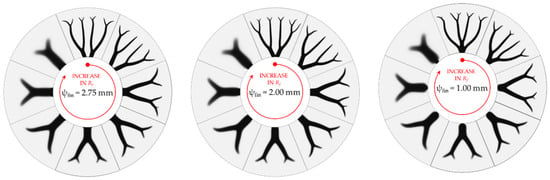
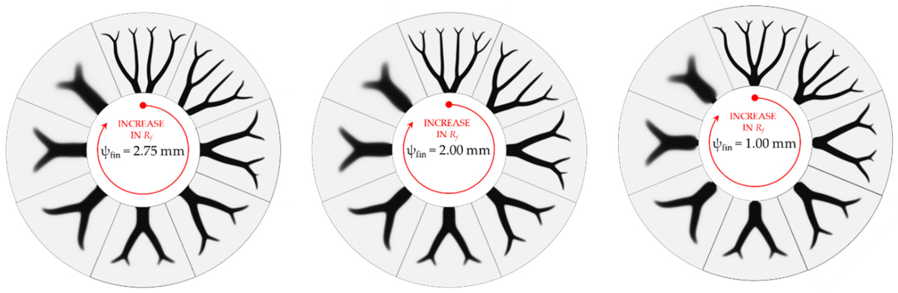
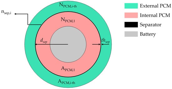
In this context, fin arc length (ψfin), i.e., the arc of the circumference used to determine the base of the fin, and diffusion coefficient (Rf) have a primary role in TO design, so some parametric analysis is first performed. In particular, structures have been obtained for values equal to 2.75 mm, 2.00 mm and 1 mm for fin arc length and 0.10 mm, 0.15 mm, 0.20 mm, 0.30 mm, 0.50 mm, 0.75 mm and 1 mm for the diffusion coefficient, as shown in Figure 5.
Figure 5.
Topology optimization results obtained for different values of fin arc length, equal to 2.75 mm, 2.00 mm and 1.00 mm, and diffusion coefficients ranging from 0.10 mm to 1.00 mm.
Figure 5 shows that variations in the diffusion coefficient and the fin arc length lead to different optimized geometries. A lower diffusion coefficient promotes increased fin branching, allowing the structure to extend further into the PCM domain. In contrast, changes in the fin arc length primarily affect the base structure of the fins, with limited influence on their overall branching pattern. In general, the change in these two parameters involves different temperature results, as shown later. The first comparison between the different configurations was made considering the objective function, i.e., the average temperature of the whole domain (Tavg) as follows in Equation (15), obtained during the topology optimization as listed in Table 3.
Table 3.
Objective function values for different fin arc length and diffusion coefficient values.
Table 3 shows that the objective function exhibits a slight inverse relationship with the diffusion coefficient. Specifically, reducing the diffusion coefficient leads to an increase in the objective function. In contrast, reducing the fin arc length does not alter the overall trend and results only in a marginal decrease in the objective value.
This result can be explained by the increased branching obtained at lower diffusion coefficients, which enhances heat spreading within the PCM domain (higher heat transfer area) and promotes a more uniform temperature distribution. As a result, the average temperature in the PCM increases. This effect significantly influences both the maximum battery temperature and the melting evolution, as discussed in the Results section.
2.3.2. PCM in Series
The maximum temperature reached by the battery strongly depends on the discharge rate. Higher discharge rates, such as 5C, lead to significantly higher temperatures, which may exceed the prescribed critical limit. Therefore, in cases where the critical temperature is exceeded, a series arrangement of PCM layers is implemented to provide additional thermal buffering. The series arrangement of PCMs requires a separating material between adjacent PCM layers to prevent mixing during and after the melting process. Accordingly, a separator is introduced between each PCM layer, with the number of separators depending on the number of PCM layers employed.
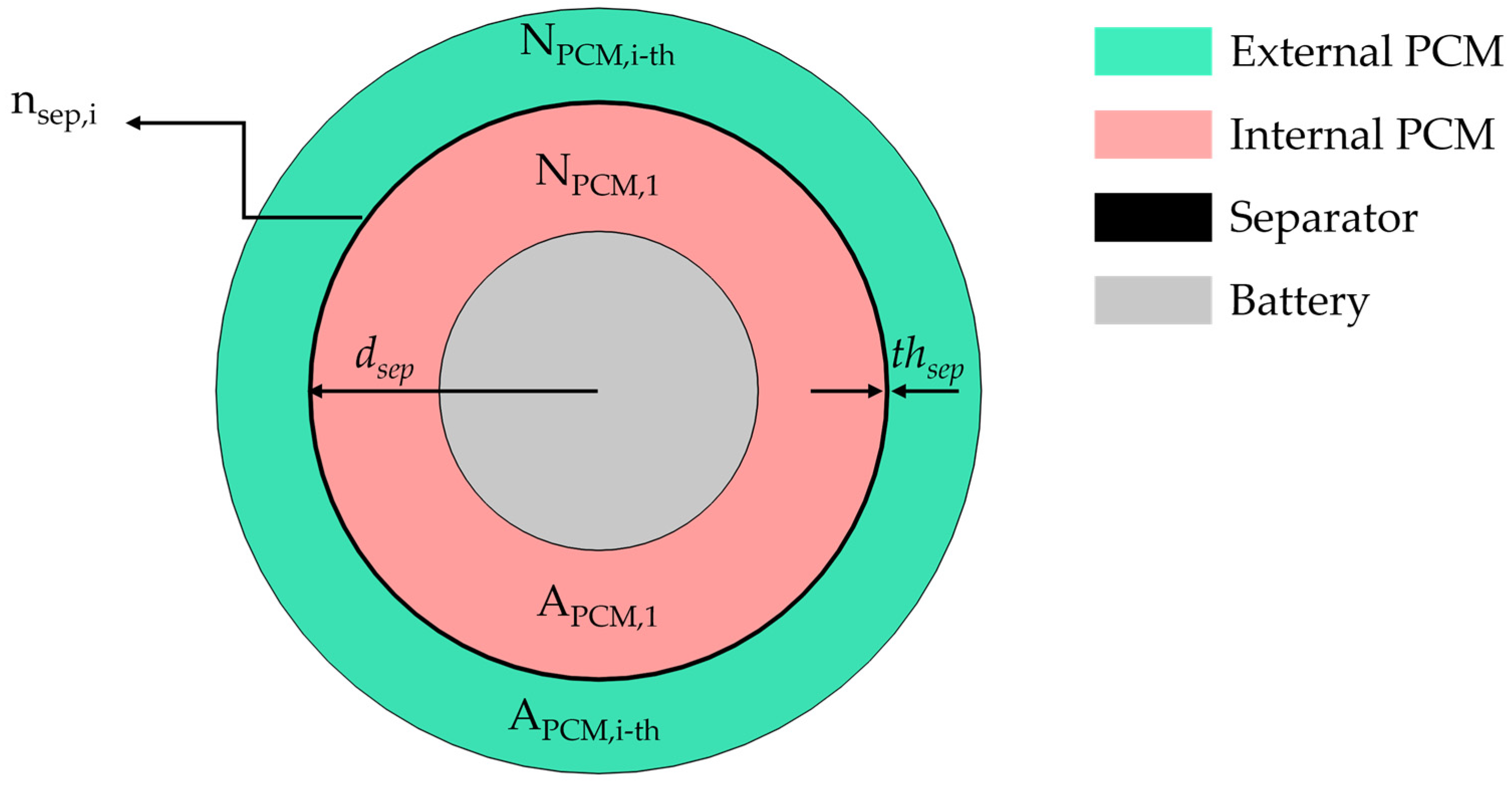
The configuration with N PCM layers in series (NPCM) is illustrated in Figure 6.
Figure 6.
Schematic representation of the PCM-in-series configuration with main dimensions.
In Figure 6, Nsep, dsep and thsep represent the number of separator layers that is equal to the number of PCMs minus 1, the radial distance between the separator to the battery center, which could be a variable, and the thickness of the separator, constrained to be equal to 1.05 mm. In particular, the placement of the separator, i.e., the value of dsep, involves a different amount of PCMs defined by their cross-sectional area (APCM). This solution has been considered only for the case with optimized fins because, as shown later, this allows one to reduce the battery temperatures reached. Different PCMs are evaluated, as reported in Table 2, with particular attention to their melting temperatures. The arrangement of the PCMs is also investigated by placing the low-melting-temperature PCM either adjacent to the battery and the high-melting-temperature PCM beyond the separator, or vice versa.
From a battery pack perspective, energy density is a key design parameter. To avoid penalizing this metric and to have a consistent and reliable comparison, the use of PCM layers in series does not alter the external PCM diameter (Dext,PCM), since a greater volume of PCMs could increase the thermal efficiency of the BTMS. This ensures that the overall size of the individual battery unit remains unchanged. To quantify the variation in battery available operating time (BAOT), a time percentage improvement (TPI) is defined, as reported in Equation (16):
where BAOTnew and BAOTref are the battery available operating time for new solutions, i.e., all new solutions proposed in this study, and for reference case. As already mentioned, the BAOT is defined as the earliest time at which the maximum temperature within the battery reaches the prescribed critical value, . Mathematically, it can be expressed as
where denotes time and is the maximum temperature within the battery domain . Therefore, BAOT represents the minimum time required for the battery temperature to reach the critical threshold. This parameter quantifies the duration of safe operation, as reaching the critical temperature marks the onset of potentially hazardous conditions. Beyond this threshold, continued battery use may lead to severe overheating and, in extreme cases, thermal runaway. Therefore, increasing the BAOT extends the period during which the battery can function safely, reducing the risk of critical thermal events and enhancing overall operational autonomy.
3. Results
In this section, the results regarding the thermal comparison between baseline, only PCM, and rectangular fins cases, in terms of battery available operating time and amount of PCM melted, are shown, considering only one PCM from Table 2, Crodatherm-32, and different battery discharge coefficients. The choice of Crodatherm-32 as the PCM in this first analysis is based on its melting temperature, which is below the critical limit while remaining slightly above external temperature. In addition, Crodatherm-32 has a higher latent heat than the other PCMs listed in Table 2, making it a suitable candidate for this study. Later, a comparison with the rectangular fins case, and the three analyzed fin arc length optimized configurations, obtained with topology optimization, in terms of BAOT and TPI, will be presented. Finally, only the best solution among the three fin arc lengths will be evaluated to study a PCM-in-series configuration to increase the battery available operating time. All these evaluations have been developed considering the time percentage improvement to evaluate the best solution.
3.1. Thermal Comparison Between Baseline, Only PCM, and Rectangular Fins Cases
The first analysis concerns the battery temperature evolution and the corresponding melting behavior over time for the baseline, PCM only, and rectangular fin configurations. The evaluation focuses on the battery available operating time.
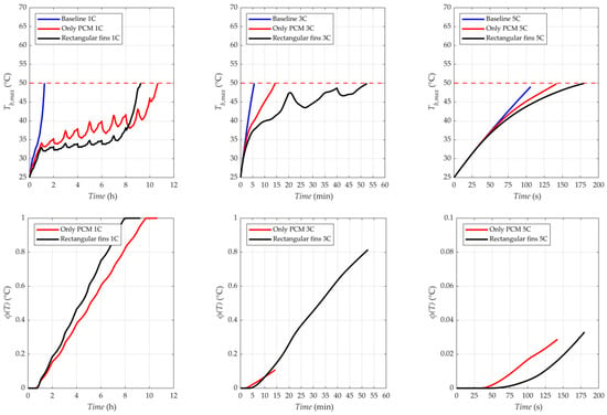
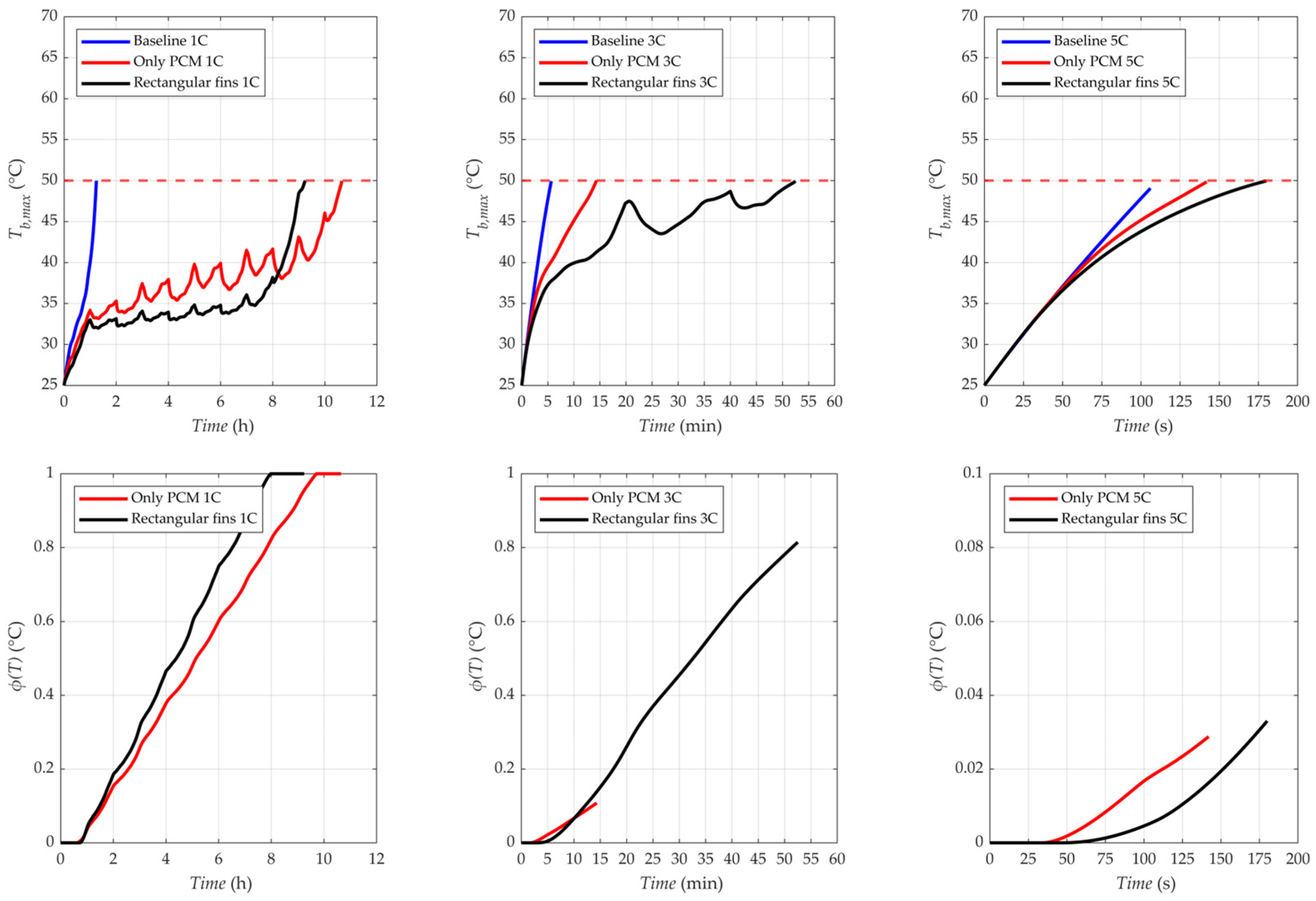
The temperature and melting evolution as a function of time for discharge rates of 1C, 3C, and 5C, are shown in Figure 7.
Figure 7.
Maximum temperature evolution in time of battery (up) and melting evolution in time of the PCM (down) for baseline (left), only PCM (center), and rectangular fins (right) cases for discharge coefficients equal to 1C, 3C and 5C.
Figure 7 illustrates the variation in BAOT as a function of the discharge rate. A substantial reduction in operating time is observed when increasing the discharge coefficient, ranging from several hours under 1C conditions to only a few seconds at 5C. This pronounced decrease is primarily attributed to the significant rise in heat generation—especially for the irreversible heat generation —at higher discharge rates, which also intensifies the temperature gradient between the battery core and the outer region. The magnitude of this radial temperature difference increases with increasing discharge coefficient, accelerating the attainment of the critical temperature limit. Overall, the incorporation of PCM enhances the BAOT due to the latent heat absorption associated with the solid–liquid phase transition. This mechanism effectively delays the temperature rise, allowing the battery to remain below the critical threshold for a longer duration compared to configurations without PCM. However, the addition of fins does not universally improve performance. At low discharge rates, e.g., 1C, a substantial fraction of PCM melts even in the absence of fins. In this regime, fins accelerate heat transfer within the PCM domain, thereby shortening the overall melting duration. As a consequence, the latent heat is depleted more rapidly, the system transitions earlier to sensible heat storage, and the battery temperature rises more abruptly. This behavior ultimately reduces the BAOT. Conversely, at higher discharge rates (3C and 5C), the amount of PCM melted without fins is limited due to insufficient heat diffusion within the PCM domain. In these cases, the presence of fins enhances thermal spreading, promotes a greater fraction of melted PCM, and improves latent heat utilization. As a result, the BAOT increases compared to the corresponding configurations without fins. Table 4 reports the time percentage improvement (TPI), which quantifies the relative variation in BAOT for each configuration with respect to the baseline case, thereby providing a comparative assessment of the effectiveness of the proposed thermal management strategies.
Table 4.
Time percentage improvement (TPI) for only PCM and rectangular fin cases with respect to the baseline case.
In Table 4, it is possible to see that the TPI has a higher increase with rectangular fins for 3C and 5C cases, while for the 1C case using only the PCM is better. The decrease in TPI for the 1C case, so in BAOT, when comparing PCM and rectangular fins, allows one to exclude this case up to now. However, for the next analyses the objective will be to improve this parameter for 3C and 5C cases; thus, emphasis will be given only to 3C and 5C cases.
3.2. Topology Optimized Fins and Comparison with Rectangular Fins Case
Table 3 lists the dependence of the objective function on the diffusion coefficient (Rf), but it needs to be evaluated. For this reason, in this section, a first analysis on maximum temperature reached inside the PCM domain for only one fin arc length value equal to 2.75 mm (since in Table 3 it has been shown that there is not much difference across the cases investigated), is carried out. The objective function analysis was performed by changing the diffusion coefficient (Rf) in order to validate the objective function trend for 3C and 5C cases, as listed in Table 5.
Table 5.
Objective function (Tavg) for different values of diffusion coefficients and discharge coefficients equal to 3C and 5C.
For the 3C configuration, the objective function values show an almost constant trend within the PCM domain for lower diffusion coefficient values, as reported in Table 5, whereas a clear difference is observed between the lowest and highest diffusion coefficients. In contrast, for the 5C configuration, the objective function exhibits a pronounced reduction even at lower diffusion coefficient values and remains significantly different between the first and last cases. The distinct behavior observed at low diffusion coefficients arises from the higher heat generation in the 5C case compared to the 3C case, for which the increased branching associated with lower diffusion coefficients has a more pronounced effect. Overall, the trends observed for both 3C and 5C configurations confirm that reducing the diffusion coefficient—thereby increasing branching—enhances heat dissipation in a more uniform manner within the PCM domain, leading to an increase in the objective function, i.e., the average temperature within the PCM domain.
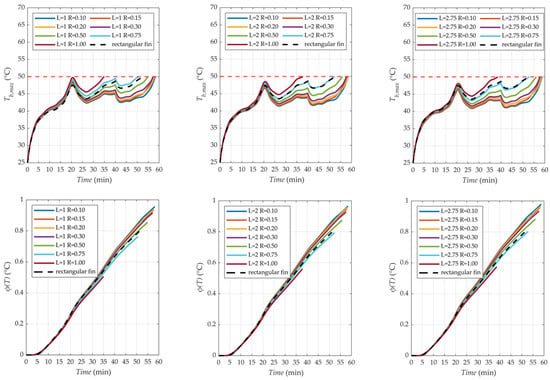
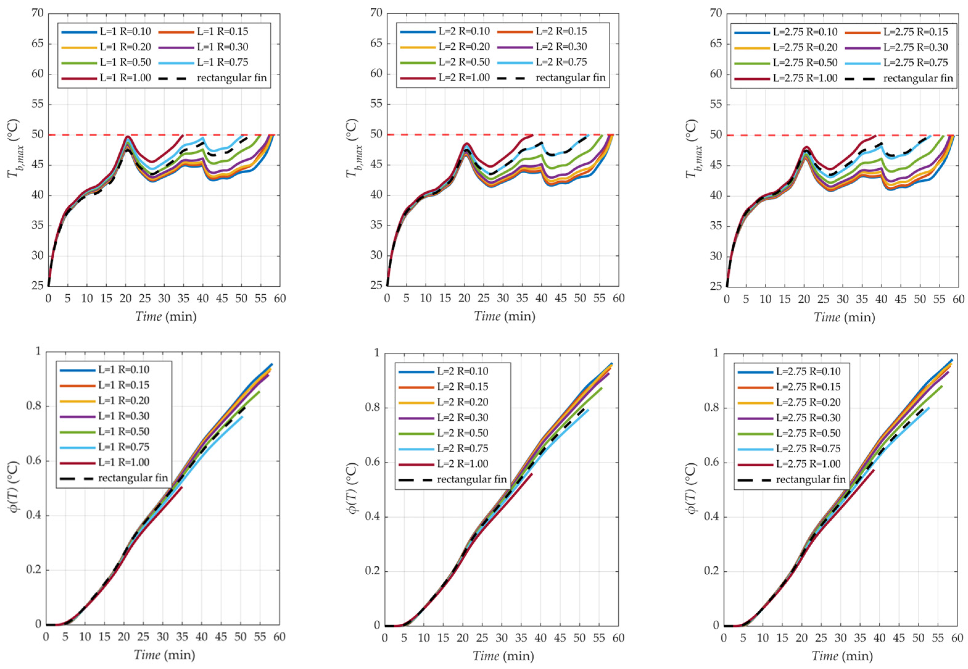
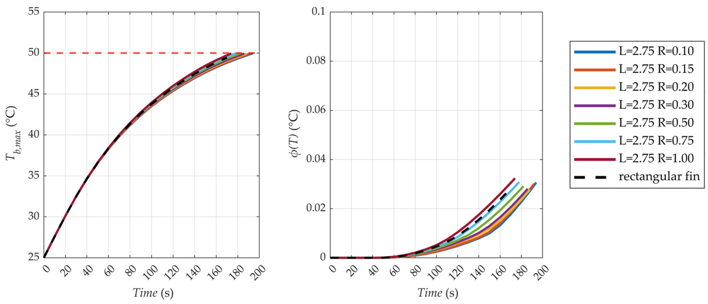
After the objective function comparisons with reference to the average temperature, a comparison in terms of maximum temperature, considering different arc length and diffusion coefficient configurations, was performed, with reference to the case with 3C, as shown in Figure 8. In addition, the melting range for the same cases is shown in order to explain what happens inside the PCM domain with these different configurations.
Figure 8.
Maximum temperature evolution in time of battery (up) and melting evolution in time of the PCM (down) for optimized fin cases with a discharge coefficient equal to 3C, three fin arc length configurations, and all diffusion coefficients.
Overall, the configuration with a fin arc length of 2.75 mm provides a slight increase in the battery available operating time compared to the other configurations. For this specific arc length, only the optimized fin with a diffusion coefficient of 1.00 mm performs worse than the rectangular fin. For lower arc length values, cases with a diffusion coefficient of 0.75 mm also show worse performance than the reference case. Furthermore, the melting behavior analysis highlights that reducing the diffusion coefficient, i.e., increasing the fin branching, leads to a more uniform heat dissipation within the PCM domain. Low diffusion coefficient values allow the optimized fins to reach distant regions of the PCM, promoting a more homogeneous melting process compared to fins characterized by higher diffusion coefficients. As a result, the battery temperature evolution over time differs from that observed with rectangular fins, yielding an overall increase in the available battery operating time. From the analysis of the results (Figure 8) and the TIP evaluation reported in Table 5, it can be concluded that the configuration with a fin arc length of 2.75 mm represents the most suitable solution, and is therefore selected for subsequent analyses. The remaining configurations show a reduction in battery operating time due to the modification of the contact area between the battery and the fin, which negatively affects the heat transfer effectiveness. After the 3C case analysis, it is important to evaluate the 5C case, i.e., the most critical case that would prove the effective improvement in TPI with the use of optimized fins. The temperature evolution in time and the melting range, as shown in Figure 9, are important parameters to understand what happens and why the battery available operating time in this case is very low.
Figure 9.
Battery temperature (left) and melting evolution in time (right) for rectangular fin and optimized fin (ψfin = 2.75 mm) cases for discharge coefficient equal to 5C.
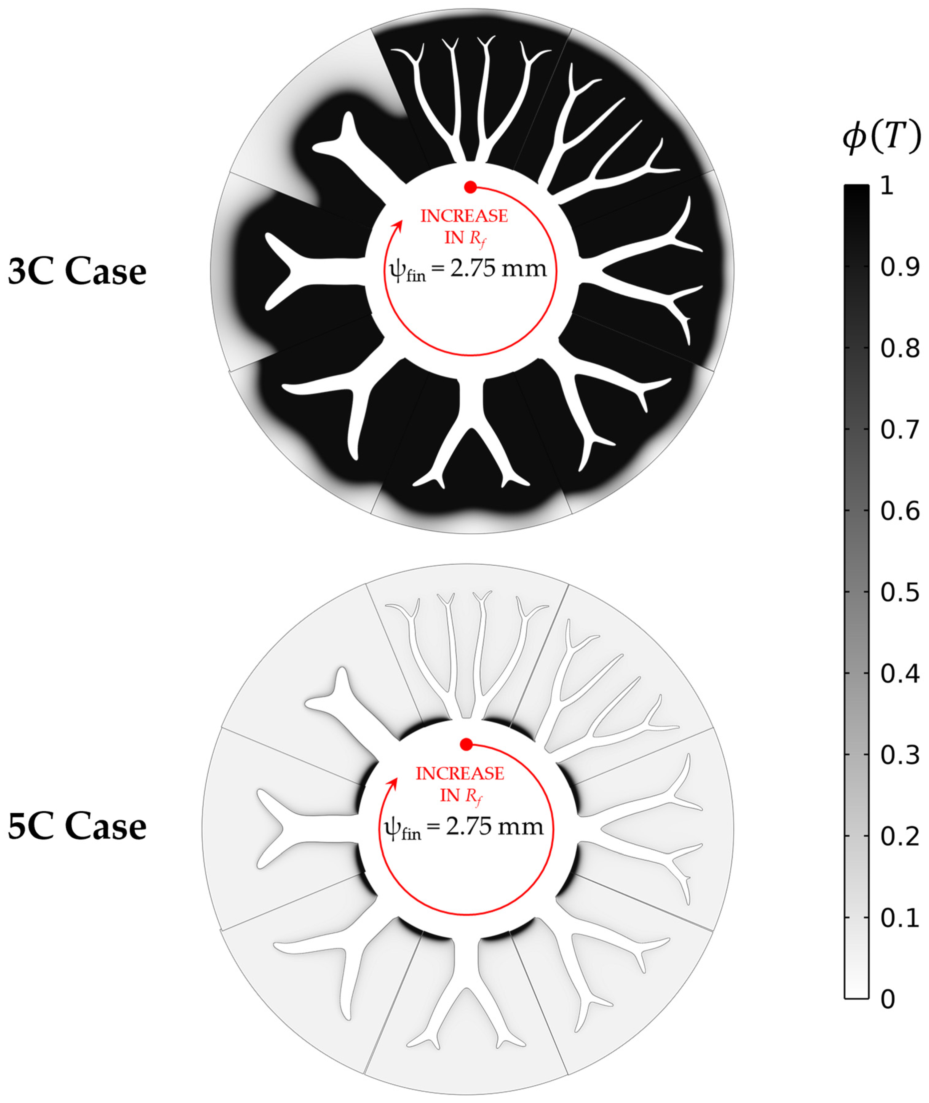
Figure 9 shows that the shorter melting time achieved with topology-optimized fins characterized by low diffusion coefficients leads to a slight increase in the time percentage improvement (TPI), as reported in Table 6. However, for the 5C case, the TPI remains very limited, on the order of only a few seconds. This behavior is attributed to the large temperature gradient between the battery core and the outer region under 5C discharge conditions. In this regime, heat generation is so intense that the fins do not have sufficient time to effectively redistribute heat within the PCM domain, unlike the 3C case. Indeed, for the 3C discharge rate, the fraction of melted PCM at the instant when the battery temperature reaches the critical limit is significantly higher than in the 5C case, as illustrated in Figure 10.
Table 6.
Time percentage improvement (TPI) for different topology solutions with respect to the rectangular fins case.
Figure 10.
Melting field for optimized fin (ψfin = 2.75 mm) cases for discharge coefficients equal to 3C (up) and 5C (down) when the battery temperature, for diffusion coefficients ranging from 0.10 mm to 1.00 mm, reaches the critical limit.
In general, the optimized fin obtained with a diffusion coefficient of 1.00 mm performs worse than the rectangular fin, as also observed for the 3C case. This behavior arises because the optimized fin corresponding to the highest diffusion coefficient exhibits limited branching, resulting in a geometry that is less effective in enhancing thermal spreading. Moreover, the material adopted for the optimized fin has a lower thermal conductivity than that of the rectangular fin, further reducing its heat transfer capability. It is important to emphasize the role of the diffusion coefficient, which significantly influences the melting time, the objective function value (i.e., the mean PCM temperature), and the temporal temperature evolution. Conversely, variations in the fin arc length primarily affect the battery temperature relative to the rectangular fin configuration.
Finally, particular attention should be given to the ability of optimized solutions to extend the battery operating time. The accelerated melting behavior promoted by certain optimized geometries enhances latent heat utilization, thereby delaying the attainment of the critical temperature limit compared to the rectangular fin case.
3.3. Results of PCM in Series
Despite the increase in battery available operating time achieved through the use of optimized fins, an additional configuration is proposed to further enhance the time percentage improvement (TPI). The solution combining optimized fins with a single PCM layer increases the battery available operating time for the 3C and 5C cases, as reported in Table 5, whereas a reduction is observed for the 1C case.
The objective is therefore to further improve this parameter under both moderate and high discharge rates without resorting to alternative strategies, such as active thermal management systems. To this end, a potential solution consists of employing multiple PCMs arranged in series, as illustrated in Figure 6, in order to tailor the melting behavior to the spatial temperature distribution within the battery. For both discharge rates, the objective function remains the average PCM temperature. However, previous results have shown that, in the 3C case, the PCM is not completely melted when the battery reaches the critical temperature limit, whereas in the 5C case, the melting process occurs too rapidly. Accordingly, the design objective differs for the two operating conditions: for the 3C case, the aim is to prolong the time required for complete melting of all PCM layers, while for the 5C case, the goal is to increase the fraction of PCM melted before the critical temperature is reached. The PCMs considered for the series configurations are listed in Table 2. Different combinations were investigated to identify the most effective arrangement. Focusing initially on the 3C case, a two-layer PCM configuration was analyzed using only the optimized fins obtained with diffusion coefficients of 0.10 mm and 1.00 mm, since the remaining cases exhibit intermediate behavior, as shown in Figure 11.
Figure 11.
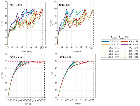
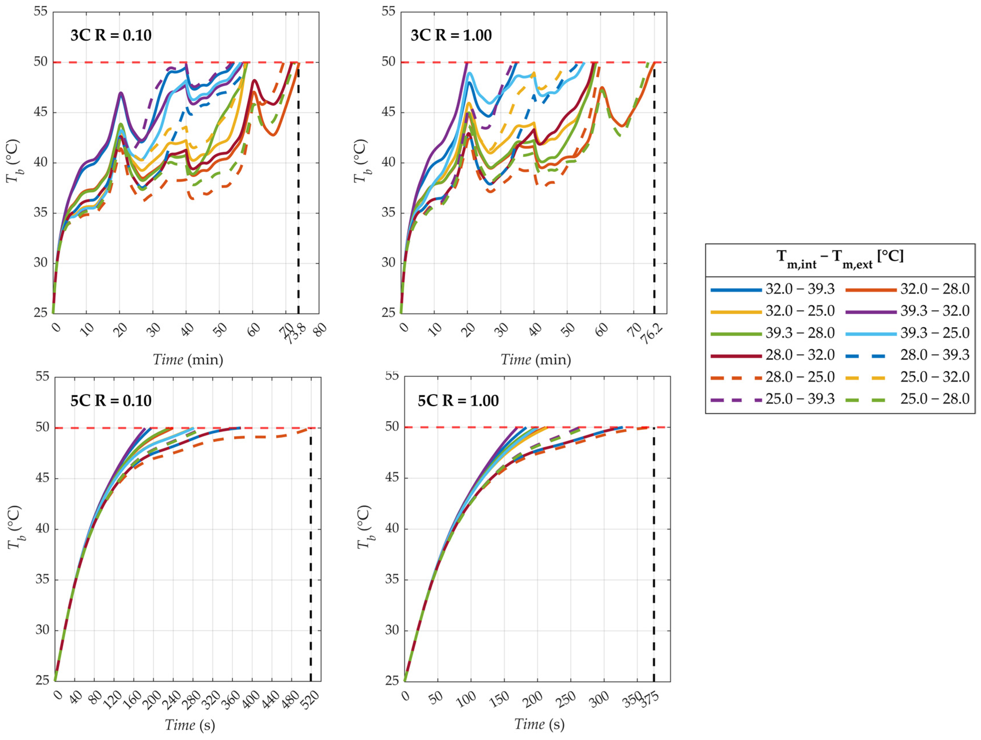
Battery available operating time (BAOT) for optimized fins with different combinations of PCM in series, indicated by melting temperatures, whose properties are shown in Table 2, for diffusion coefficients equal to 0.10 mm (left) and 1.00 mm (right) and discharge coefficients equal to 3C (up) and 5C (down).
Figure 11 demonstrates that arranging PCMs in series extends the battery available operating time (BAOT) in all investigated cases, as evidenced by the melting evolution curves, with a particularly pronounced improvement for the 5C discharge rate. Numerous configurations can be generated by combining the PCMs listed in Table 2. Focusing first on the 3C case, the optimal solution is no longer associated with a low diffusion coefficient, but rather with a higher one. In this regime, a configuration characterized by a reduced heat dissipation capability proves advantageous. Specifically, the lower effective heat spreading associated with the optimized fin having a diffusion coefficient of 1.00 mm increases the time required for complete melting of the PCM. Although this fin exhibits lower thermal conductivity than the rectangular fin, its limited branching reduces heat transfer toward regions distant from the fin arc. As a result, the melting process is more gradual, which is beneficial under 3C conditions.
The most effective PCM arrangement for the 3C case consists of a material with a higher melting temperature in the inner region and a material with a lower melting temperature in the outer region. In this configuration, the external PCM melts first, facilitating heat transfer toward the outer boundary, while the internal PCM undergoes phase change at a later stage. This sequential melting process significantly increases the BAOT.
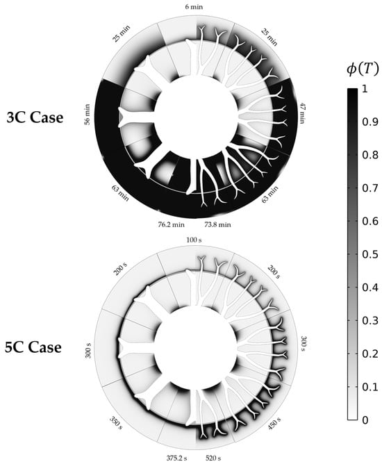
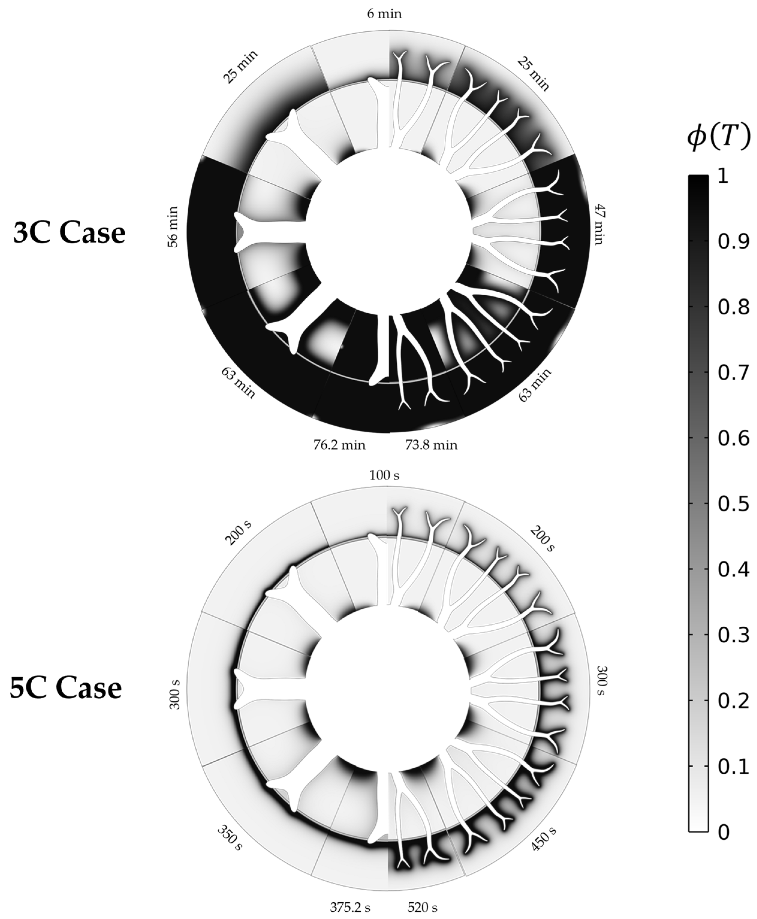
For the 5C case, the optimal solution remains the configuration with a diffusion coefficient of 0.10 mm, as this arrangement enables more effective heat dissipation compared to the other geometries. The results further indicate that selecting a PCM with an excessively low melting temperature does not improve the BAOT, since premature melting limits the effective utilization of latent heat and prevents adequate thermal buffering. Consequently, the optimal PCM arrangement for the 5C case is in agreement with that identified for the 3C case: the PCM with the lower melting temperature should be placed in the outer region to ensure rapid melting under intense heat generation. Moreover, the PCM pair that yields the best performance differs between the two discharge rates. In particular, for the 3C case, a PCM with a higher melting temperature can be adopted compared to the optimal PCM selected for the 5C case. This happens because, in the 5C case, a much larger amount of heat must be dissipated in a shorter time compared to the 3C case, and this can only be achieved by using PCMs with a lower melting temperature. To further elucidate the different thermal behaviors under 3C and 5C conditions, the melting fields for both cases are shown in Figure 12.
Figure 12.
Melting field of PCM-in-series best solutions (32–28 for 3C and 28–25 for 5C) for diffusion coefficients equal to 0.10 mm and 1.00 mm, discharge coefficients equal to 3C and 5C, and for different simulation times.
The corresponding increase in time percentage improvement (TPI), evaluated between the best two-PCM configuration and the best single-PCM configuration (i.e., the case with a diffusion coefficient of 0.10 mm), is reported in Table 7. The BAOT for the single-PCM configuration is denoted as BAOT1PCM, whereas the BAOT for the two-PCM configuration is denoted as BAOT2PCM. Figure 12 shows that for the 3C case, the use of the optimized fin with a high diffusion coefficient allows one to increase the time until the PCM is fully melted. In addition, Table 6 confirms the increase in TPI for the solution with PCM in series compared to the one with one PCM.
Table 7.
Time percentage improvement (TPI) between best solutions with PCM in series (BAOT2PCM), configurations 32–28 and 28–25 for 3C and 5C cases, respectively, and the best solution with one PCM (BAOT1PCM) at ψfin = 2.75 mm.
Following this analysis, battery temperature uniformity should also be considered as a key performance indicator. Specifically, the evaluation was conducted for 3C and 5C cases considering the baseline case, rectangular fins case, and only the optimal solution for optimized fins cases with one PCM and PCMs in series. This parameter is listed in Table 8 as the temperature difference between the maximum and minimum temperature inside the battery domain. The time considered for this comparison is the moment when the temperature in the baseline case reached critical condition.
Table 8.
Uniformity of battery temperature, in terms of temperature difference, at the time when the baseline case reached critical condition.
It is worth noting that this thermal gradient becomes more pronounced as the BAOT increases. This occurs because enhanced cooling significantly lowers the outer surface temperature, thereby inducing a steeper internal gradient. However, this localized variance should not be a major cause for concern. The most critical temperature uniformity issues typically involve temperature imbalances between different cells, whereas the gradient discussed here reflects an intra-cell variance at a single snapshot in time. Ultimately, this internal gradient is an intrinsic consequence of the battery’s low radial thermal conductivity, where the internal battery layers (electrodes, separators, and current collector) act as thermal resistances in series, a limitation that has also been analyzed by [19].
4. Discussion
The analysis of the battery available operating time (BAOT) and the time percentage improvement (TPI) demonstrates that employing PCM layers arranged in series significantly enhances both metrics, thereby extending the duration of safe and efficient battery operation. Importantly, when the same initial PCM domain diameter is maintained, the volumetric energy density of the prospective battery pack remains unaffected.
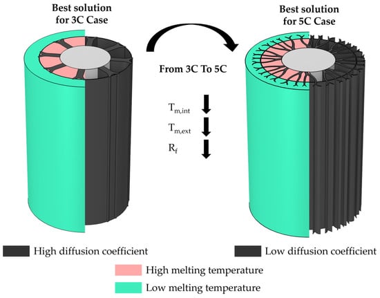
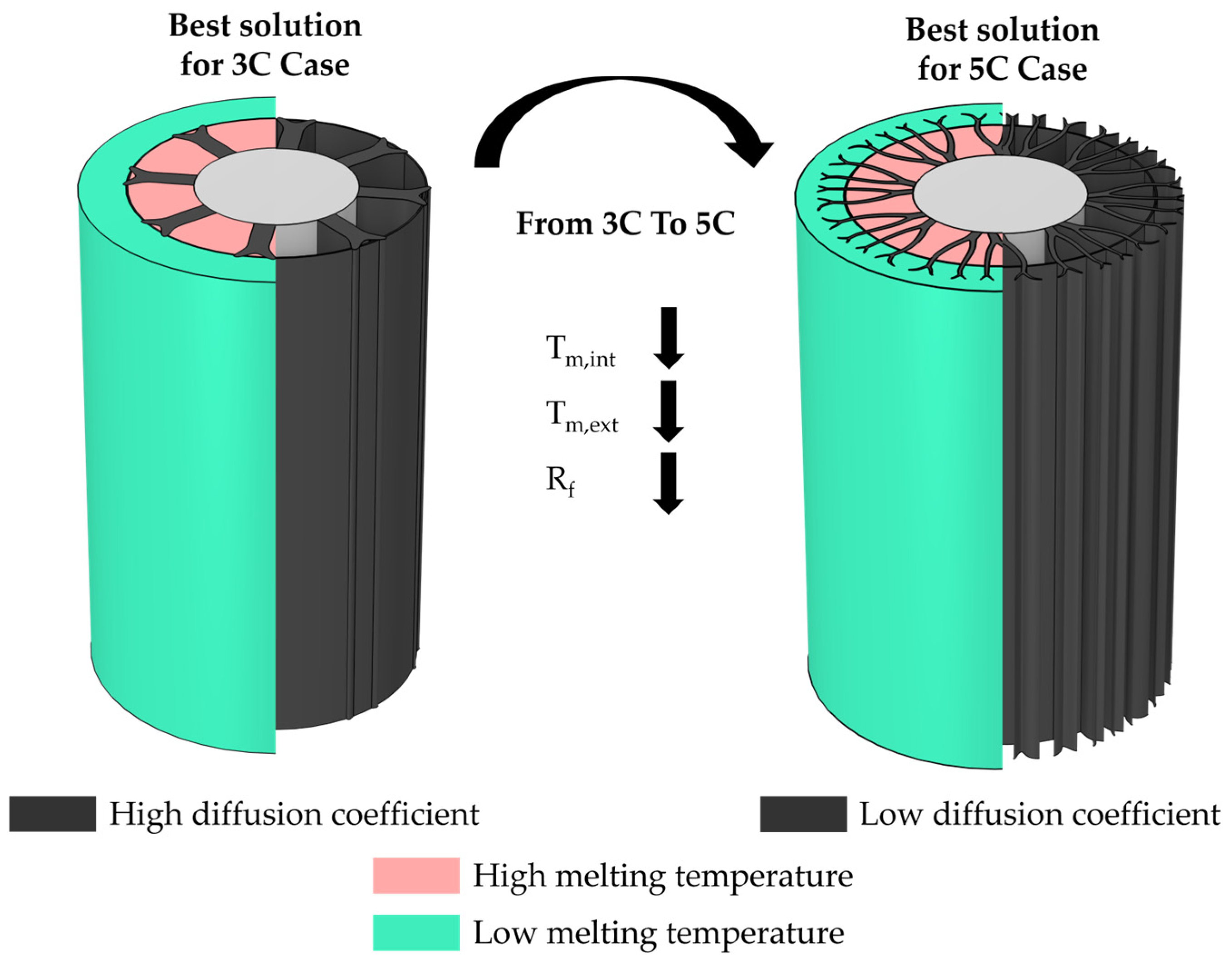
A key outcome of this study is the identification of distinct optimal PCM combinations and topology-optimized fin configurations, characterized by different diffusion coefficients, for 3C and 5C discharge rates. This result provides practical guidelines for selecting the most appropriate passive thermal management configuration according to the expected operating conditions of the battery.
Specifically, under moderate discharge rates (3C), the preferred configuration consists of a PCM arrangement with a relatively high diffusion coefficient and a melting temperature that decreases radially from the inner to the outer layer. At high discharge rates (5C), the optimal configuration is characterized by a lower diffusion coefficient, a radially decreasing melting temperatures from the inner to the outer, and a lower melting temperature of the PCMs employed, as illustrated in Figure 13. These differing configurations reflect the distinct thermal management requirements of the two operating conditions: for 3C discharge, it is advantageous to prolong the complete melting time of the PCM, whereas for 5C discharge, maximizing the fraction of melted PCM is more beneficial.
Figure 13.
Best solutions for series PCMs at discharge coefficients of 3C (left) and 5C (right).
Regarding the separator between PCM layers, the same material used for the topology-optimized fins was adopted. This choice enables the fabrication of a single integrated component, comprising both fins and separators, via additive manufacturing. Electrical conduction is prevented by the presence of an insulating layer positioned between the battery and the fins.
5. Conclusions
This study presented a comprehensive numerical investigation of a passive battery thermal management system based on topology-optimized fins coupled with phase change materials (PCMs), considering both single-PCM and PCM-in-series configurations. The primary objective was to extend the battery available operating time (BAOT), defined as the time required for the battery temperature to reach the critical limit of 50 °C, under different discharge rates. A density-based topology optimization framework was adopted to design fins by varying fin arc lengths and diffusion coefficients. This approach enabled the identification of optimized fin geometries and heat transfer characteristics tailored to specific operating conditions. PCMs were selected as a passive solution due to their no-energy requirement, while the choice of the PCM type was constrained by safety considerations and melting temperature requirements. The results highlight intrinsic limitations of PCMs in battery thermal management, since rapid charge–discharge cycles limit sufficient solidification time and reduce full exploitation of latent heat storage. The discharge rate was identified as a key parameter governing the effectiveness of fins and PCMs. At low discharge rates, fins are not recommended as they accelerate PCM melting and reduce the BAOT. Conversely, at medium and high discharge rates (e.g., 3C and 5C), topology-optimized fins significantly enhance thermal performance. For single-PCM configurations, the numerical results consistently indicate that fins characterized by low diffusion coefficients provide the best performance, independently of the discharge rate, with BAOT improvement, quantified by a time percentage improvement (TPI), of 10.61% and 7.69% for the 3C and 5C cases, respectively. Performance is further enhanced by combining four PCMs with different melting temperatures in a two-series arrangement. A clear dependence on the discharge rate is observed. At moderate conditions (3C), the optimal configuration uses fins with high diffusion coefficients and a decreasing melting temperature from the inner to the outer PCM layer. At high discharge rates (5C), the best solution involves fins with low diffusion coefficients combined with a decreasing melting temperature gradient across the Phase Change Material (PCM) layers, utilizing PCMs with overall lower melting points in both sections compared to the 3C case. These contrasting trends observed at different discharge rates—specifically the shift in optimal diffusion coefficients and the variation in PCM melting temperatures—stem from distinct thermal management requirements: at 3C, extending PCM melting time is crucial, while at 5C, maximizing the melted PCM fraction is dominant. The results demonstrate that a single, universal arrangement for the series-PCM configuration is not optimal across all operating conditions. These optimized PCM-in-series configurations significantly improve the BAOT, with TPI values of 22.92% (3C) and 62.50% (5C) compared to the single PCM solution with the same diffusion coefficient Rf and fin arc length ψfin. Overall, coupling topology-optimized fins with tailored PCM arrangements is an effective passive strategy for battery thermal management under medium-to-high discharge rates. The results provide design guidelines for selecting appropriate fin diffusion properties and the optimal arrangement of PCM melting temperatures, enabling longer battery operating times without increasing system complexity or energy consumption. Possible future developments may focus on the integration of the proposed passive PCM–fin systems with active thermal management solutions. Such hybrid strategies could combine the advantages of latent heat storage with on-demand active cooling, reducing energy waste while still ensuring efficient and reliable thermal control of battery systems under a wide range of operating conditions.
Author Contributions
Conceptualization, V.O., A.F., M.I. and N.B.; methodology, V.O., F.P. and A.F.; software, V.O. and A.F.; validation, V.O., A.F. and M.I.; formal analysis, V.O., A.F. and M.I.; investigation, M.I., A.F. and F.P.; resources, M.I., N.B. and R.F.D.M.; data curation, M.I., F.P. and A.F.; writing—original draft preparation, V.O. and A.F.; writing—review and editing, M.I., N.B., F.P. and R.F.D.M.; visualization, V.O., A.F. and F.P.; supervision, M.I., N.B. and R.F.D.M.; project administration, M.I., N.B. and R.F.D.M.; funding acquisition, M.I. and R.F.D.M. All authors have read and agreed to the published version of the manuscript.
Funding
This work was supported by the Italian Government MUR Grant No. P2022NYPHL–PRIN 2022 PNRR “VISIONS: eVolutIonary deSign of InnOvative heat traNsfer deviceS”, funded by the European Union—Next Generation EU.
Data Availability Statement
The original contributions presented in this study are included in the article. Further inquiries can be directed to the corresponding author.
Conflicts of Interest
The authors declare no conflicts of interest.
Abbreviations
The following abbreviations are used in this manuscript:
| Latin Letters | ||
| Symbol | Description | Unit |
| A | area | (m2) |
| Bi | Biot number | (-) |
| C | capacity | (C) |
| c | specific heat | (J kg−1 K−1) |
| D | diameter | (m) |
| d | distance | (m) |
| dVoc/dT | entropic coefficient | (mV K−1) |
| H | height | (m) |
| hconv | convective heat transfer coefficient | (W m−2 K−1) |
| I | current intensity | (A) |
| k | thermal conductivity | (W m−1 K−1) |
| L | length | (m) |
| LH | latent heat | (kJ kg−1) |
| heat generation | (W) | |
| R | internal resistance | (Ω) |
| Rf | diffusion coefficient | (m) |
| SoC | State of Charge | (-) |
| th | thickness | (m) |
| t | time | (s) |
| T | temperature | (K) |
| Tm | melting temperature | (K) |
| ΔTm | melting temperature range | (K) |
| Vn | nominal voltage | (V) |
| VOC | open circuit voltage | (V) |
| W | width | (m) |
| Subscripts | ||
| Symbol | Description | |
| amb | environment | |
| avg | average | |
| b | battery | |
| ext | external | |
| fin | fin | |
| int | internal | |
| irr | irreversible | |
| l | liquid | |
| r | radial direction | |
| ref | reference | |
| rev | reversible | |
| s | solid | |
| sep | separator | |
| z | axial direction | |
| Greek Letters | ||
| Symbol | Description | Unit |
| α | angular spacing between fins | (°) |
| γ | design variable | (-) |
| filtered design variable | (-) | |
| projection point | (-) | |
| projection slope | (-) | |
| melting fraction | (-) | |
| Ψ | arc length | (mm) |
| ƞ | penalization factor | (-) |
| ρ | density | (kg m−3) |
| Abbreviations | ||
| Symbol | Description | |
| AM | Additive Manufacturing | |
| BAOT | Battery available operating time | |
| BTMS | Battery thermal management system | |
| EV | Electric vehicle | |
| Li-ion | Lithium-ion | |
| PCM | Phase change material | |
| TO | Topology optimization | |
| TPI | Time percentage improvement |
References
- Zhu, Y.; Chen, Z. Predicting the Temperature of the Lithium-Ion Battery and Liquid Fraction of PCM in PCM-Based Thermal Management Systems: A Numerical Study. Therm. Sci. Eng. Prog. 2025, 67, 104195. [Google Scholar] [CrossRef] [Scilit]
- Olabi, A.G.; Abbas, Q.; Shinde, P.A.; Abdelkareem, M.A. Rechargeable Batteries: Technological Advancement, Challenges, Current and Emerging Applications. Energy 2023, 266, 126408. [Google Scholar] [CrossRef] [Scilit]
- Wang, Y.; Wang, C.; Li, D.; Xi, H. Numerical Investigation for a Coupled Fin-PCM-Liquid Cooling System under Multi-Scenario of Thermal Management and Thermal Runaway Mitigation in Lithium-Ion Battery Modules. J. Energy Storage 2025, 140, 119078. [Google Scholar] [CrossRef] [Scilit]
- Rodrigues, M.-T.F.; Babu, G.; Gullapalli, H.; Kalaga, K.; Sayed, F.N.; Kato, K.; Joyner, J.; Ajayan, P.M. A Materials Perspective on Li-Ion Batteries at Extreme Temperatures. Nat. Energy 2017, 2, 17108. [Google Scholar] [CrossRef] [Scilit]
- Shahid, S.; Agelin-Chaab, M. A Review of Thermal Runaway Prevention and Mitigation Strategies for Lithium-Ion Batteries. Energy Convers. Manag. X 2022, 16, 100310. [Google Scholar] [CrossRef] [Scilit]
- Buidin, T.I.C.; Mariasiu, F. Battery Thermal Management Systems: Current Status and Design Approach of Cooling Technologies. Energies 2021, 14, 4879. [Google Scholar] [CrossRef] [Scilit]
- He, Z.; Li, R.; Yang, L.; Mikulčić, H.; Wang, J.; Čuček, L. Performance Analysis of a Battery Thermal Management System Based on Phase Change Materials with Micro Heat Pipe Arrays. Energy Convers. Manag. 2024, 311, 118506. [Google Scholar] [CrossRef] [Scilit]
- Li, W.; Zhao, J.; Zhang, L.; Wang, J.; Zhang, X.; Zhu, Y.; Zhao, J. Thermal Management Optimization Strategy for Lithium-Ion Battery Based on Phase Change Material and Fractal Fin. J. Energy Storage 2024, 102, 114159. [Google Scholar] [CrossRef] [Scilit]
- Xiang, X.; Yang, R.; Sun, H.; Hoffman, D. Performance Improvement of a Hybrid Battery Thermal Management System with Pseudo-3D Topology Optimization. Int. J. Heat Mass Transf. 2025, 240, 126632. [Google Scholar] [CrossRef] [Scilit]
- Bernardi, D.; Pawlikowski, E.; Newman, J. A General Energy Balance for Battery Systems. J. Electrochem. Soc. 1985, 132, 5–12. [Google Scholar] [CrossRef] [Scilit]
- Wu, Q.; Huang, R.; Yu, X. Measurement of Thermophysical Parameters and Thermal Modeling of 21,700 Cylindrical Battery. J. Energy Storage 2023, 65, 107338. [Google Scholar] [CrossRef] [Scilit]
- Bergman, T.L.; Incropera, F.P.; DeWitt, D.P.; Lavine, A.S. Fundamentals of Heat and Mass Transfer; John Wiley & Sons: Hoboken, NJ, USA, 2011. [Google Scholar]
- Herbinger, F.; Groulx, D. Experimental Comparative Analysis of Finned-Tube PCM-Heat Exchangers’ Performance. Appl. Therm. Eng. 2022, 211, 118532. [Google Scholar] [CrossRef] [Scilit]
- Brent, A.D.; Voller, V.R.; Reid, K.J. Enthalpy-Porosity Technique for Modeling Convection-Diffusion Phase Change: Application to the Melting of a Pure Metal. Numer. Heat Transf. 1988, 13, 297–318. [Google Scholar] [CrossRef] [Scilit]
- Nazari Sam, M.; Caggiano, A.; Mankel, C.; Koenders, E. A Comparative Study on the Thermal Energy Storage Performance of Bio-Based and Paraffin-Based PCMs Using DSC Procedures. Materials 2020, 13, 1705. [Google Scholar] [CrossRef] [Scilit] [PubMed]
- Fan, Z.; Zhao, Y.; Liu, X.; Shi, Y.; Jiang, D. Thermal Properties and Reliabilities of Lauric Acid-Based Binary Eutectic Fatty Acid as a Phase Change Material for Building Energy Conservation. ACS Omega 2022, 7, 16097–16108. [Google Scholar] [CrossRef] [Scilit] [PubMed]
- Bendsøe, M.P.; Sigmund, O. Topology Optimization; Springer: Berlin, Heidelberg, 2004; ISBN 978-3-642-07698-5. [Google Scholar]
- Sigmund, O.; Maute, K. Topology Optimization Approaches: A Comparative Review. Struct. Multidiscip. Optim. 2013, 48, 1031–1055. [Google Scholar] [CrossRef] [Scilit]
- Taheri, P.; Yazdanpour, M.; Bahrami, M. Transient Three-Dimensional Thermal Model for Batteries with Thin Electrodes. J. Power Sources 2013, 243, 280–289. [Google Scholar] [CrossRef] [Scilit]

Disclaimer/Publisher’s Note: The statements, opinions and data contained in all publications are solely those of the individual author(s) and contributor(s) and not of MDPI and/or the editor(s). MDPI and/or the editor(s) disclaim responsibility for any injury to people or property resulting from any ideas, methods, instructions or products referred to in the content. |
© 2026 by the authors. Licensee MDPI, Basel, Switzerland. This article is an open access article distributed under the terms and conditions of the Creative Commons Attribution (CC BY) license.