


Abstract
Small-scale excavations with depths of approximately 1 to 3 m are widely conducted for purposes such as the repair of underground pipelines. In confined construction spaces, earth-retaining systems consisting of lightweight sheet-piles with struts and walers are frequently used. However, comprehensive investigations of the influence of ground conditions on member forces have not yet been conducted. Furthermore, since these temporary structures are generally not designed with seismic considerations, they may suffer damage during earthquakes depending on the soil conditions. Accordingly, this study conducted a comprehensive parametric numerical investigation to evaluate how differences in soil type, such as sandy and cohesive soils, and loading conditions during excavation and earthquake loading affect the internal forces in the supporting members. Excavation analyses using PLAXIS 3D confirmed that as the soil strength parameters (cohesion and internal friction angle) decreased, the demand on the supporting members increased and larger internal forces developed. Dynamic analyses using LIQCA 3D revealed complex behavior in which (i) earth pressure acting on the wall generated compressive forces in the struts, (ii) lateral deformation of the excavation face reduced axial forces in the struts, and (iii) when the ground liquefied, it exhibited a vibration-isolation effect, and the vibration components generated in the structural members became smaller.
1. Introduction
Small-scale excavations with depths of approximately 1 to 3 m are often undertaken for purposes such as the repair of underground pipelines. In narrow or confined areas, lightweight sheet-piles with supporting members (struts and walers) are frequently used for earth-retaining purposes. This arrangement is referred to as a “Braced double sheet-pile wall”.
Several studies have been conducted on braced double sheet-pile walls. For example, Finno et al. conducted field measurements of the deformation of braced retaining walls and adjacent ground in saturated clay during construction and performed finite-element back-analyses [1,2]. Toyosawa carried out centrifuge model tests to investigate differences in failure modes, with particular emphasis on the presence or absence of struts [3]. Karlsrud and Andresen performed a parametric study on the loads acting on retaining walls and struts in soft clay [4]. Wang compiled field monitoring data from several deep excavation projects in the soft ground of Shanghai, including wall displacements and ground surface settlements [5]. Nakai conducted centrifuge model tests using aluminum rods to simulate soil behavior, examined the deformation characteristics of various structural configurations including the present system, and subsequently performed numerical simulations using an original analysis method [6]. Bose and Som performed a finite-element-based parametric study on braced cuts, examining the effects of wall stiffness, embedment depth, and strut stiffness on deformation and internal forces [7]. Yun et al. investigated the seismic response of braced excavation systems in deep sandy ground through dynamic centrifuge tests and evaluated the effects of earthquake loading on the behavior of retaining walls and supporting members [8]. As these studies addressed static conditions, some researchers have extended the investigation to dynamic conditions. For instance, Konai examined the behavior of braced retaining structures under seismic loading through both model experiments and numerical analyses [9,10,11].
Previous studies have mainly focused on relatively large-scale excavations with depths exceeding 3 m. In contrast, studies on small-scale excavations with depths less than 3 m remain limited. In such shallow excavations, the self-supporting effect of the ground becomes relatively more significant due to the lower wall height, and the influence of soil strength parameters, such as cohesion and the internal friction angle, on the behavior of supporting members may differ from that observed in deeper excavations. The author has previously conducted studies on braced double sheet-pile walls for small-scale excavations. For example, a liquefaction analysis was performed for a braced retaining wall with an excavation depth of 2 m, and the influence of strut spacing on member forces was investigated [12]. However, studies focusing on excavations shallower than 3 m remain limited, and the influence of soil conditions on the behavior of supporting members has not yet been comprehensively clarified. Therefore, this study conducts a systematic numerical investigation in which cohesion and internal friction angle are varied to evaluate the influence of soil conditions on the member forces of sheet-piles, struts, and walers in braced double sheet-pile walls under small-scale excavation and seismic loading conditions.
2. Materials and Methods
2.1. Braced Double Sheet-Pile Walls
Braced double sheet-pile walls consist of two parallel rows of sheet-piles supported by walers and struts. In small-scale excavations, lightweight and highly durable aluminum sheet-piles are often used. Fixtures are attached to the tops of the sheet-piles, and walers are installed to connect and stabilize the upper portions of the walls. Struts are then placed between the opposing walers, acting as compression members that resist the lateral earth pressure acting on the sheet-piles. Although the sheet-piles tend to deform toward the excavation side under earth pressure, the struts provide lateral support, thereby maintaining the stability of the retaining system.
2.2. Numerical Method
In this study, PLAXIS 3D (version 2025.1.1) was used for excavation analysis (static analysis), and LIQCA 3D (version 2024) was used for dynamic analysis. The two finite-element analysis codes are described below, respectively. Although PLAXIS can perform dynamic analyses, LIQCA was adopted because this study focuses on effective stress behavior and liquefaction-induced response in saturated ground.
Table 1 summarizes the analysis cases considered in this study. The detailed analysis conditions are described in each corresponding section. Extensive parametric analyses can provide fundamental information for preliminarily assessing the need for detailed numerical analyses or additional reinforcement.
Table 1.
Factorial Table.
2.2.1. Outline of the Numerical Code PLAXIS
PLAXIS is a finite-element software widely used for geotechnical analysis of soil–structure interaction problems. It enables the simulation of excavation processes, deformation behavior, and stress distribution in ground and structures. Various constitutive models, such as Mohr–Coulomb and Hardening Soil models, can be applied to represent soil behavior. The software allows staged construction analysis, which is essential for modeling excavation sequences. In this study, PLAXIS 3D was used to evaluate the deformation and stress characteristics during excavation. For example, Ref. [13] confirmed the reproducibility of PLAXIS 3D analyses by comparing numerical results with model test results for small-scale excavations conducted in dry sand, focusing on the stresses in the sheet-piles and struts. However, the reliability of PLAXIS 3D for the present structural system has not been confirmed for moist soils, in which suction effects may not be negligible. In addition, because its applicability to the seismic behavior of this structural system has not been verified, a different numerical analysis tool, described in the following section, was used for the dynamic analyses.
2.2.2. Outline of the Numerical Code LIQCA
LIQCA is a numerical code for analyzing the seismic behavior and deformation of ground, including liquefaction phenomena, during earthquakes [14,15]. This section includes a discussion of the principles on which LIQCA is based and examples of its application.
The governing equations describing the coupling between the soil skeleton and the pore water pressure were formulated on the basis of the two-phase mixture theory [16], and a u-p formulation (where u, the displacement of the solid-phase soil skeleton, and p, the pore water pressure, are the two unknowns) was adopted in the three-dimensional analysis. The finite-element method was employed for the spatial discretization of the equation of motion, whereas the finite difference method was employed for the spatial discretization of pore water pressure in the continuity equation.
LIQCA was used in numerical analyses of the behaviors of embankments, retaining walls, and buildings, as well as in other constructions, under seismic conditions. The verification of LIQCA analyses was conducted by comparing the LIQCA results with experimental results. It was confirmed that the deformation of a sheet-pile installed in various types of ground during an earthquake can be accurately reproduced by applying LIQCA-based analyses [17]. Because liquefaction analyses have most commonly been conducted for saturated sandy ground with zero cohesion, the liquefaction analysis in this study was also performed only for cohesionless saturated sandy ground.
3. Excavation Analysis
Typical braced double sheet-pile walls were assumed, and numerical analysis was carried out using the finite-element method tool PLAXIS 3D. This tool allows the excavation process to be simulated.
3.1. Numerical Condition
3.1.1. Model
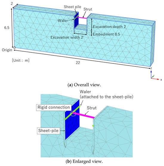
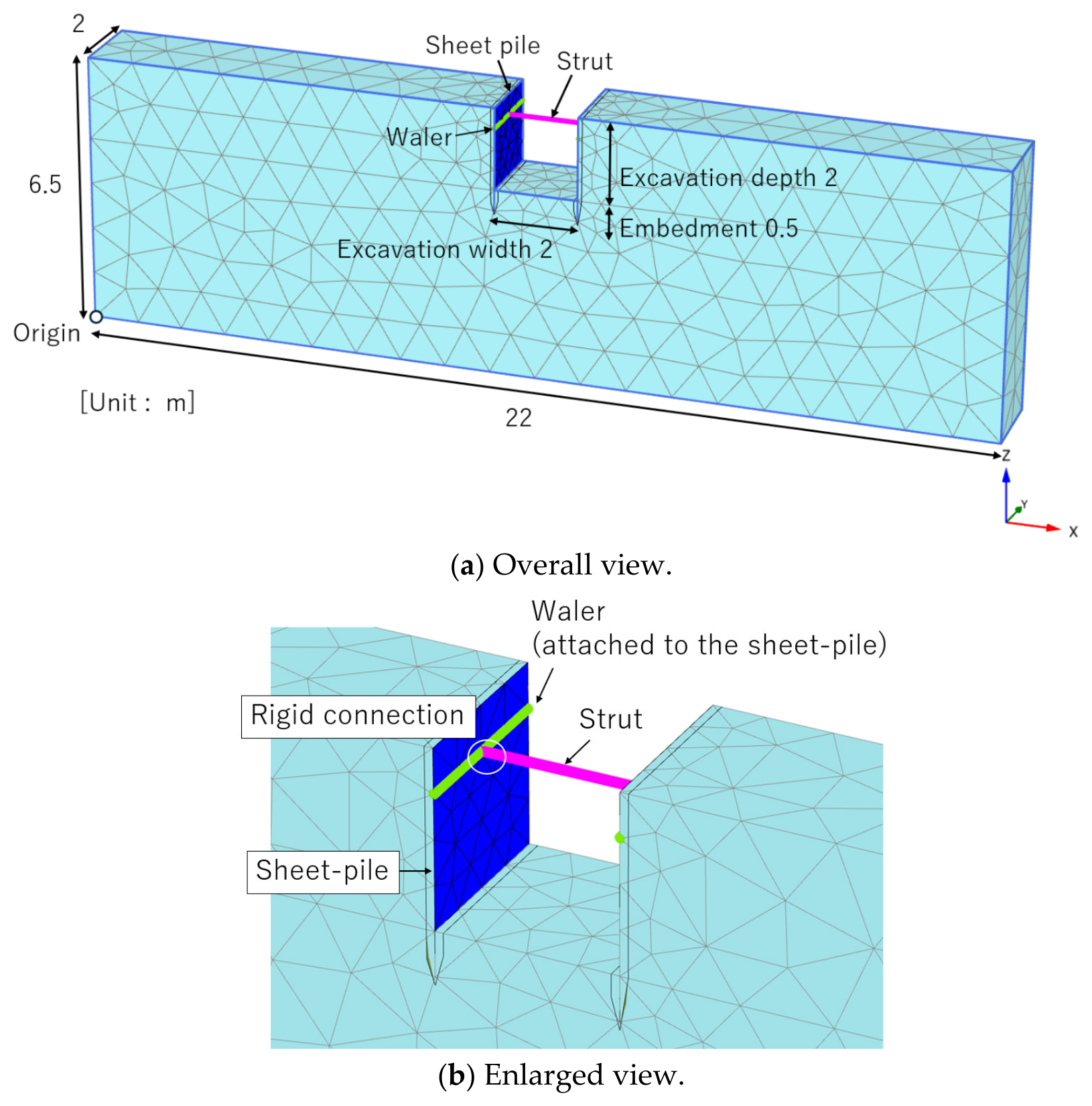
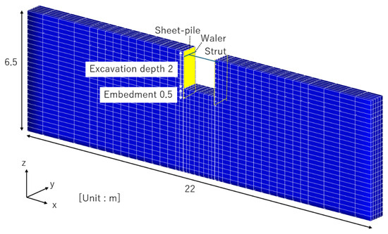
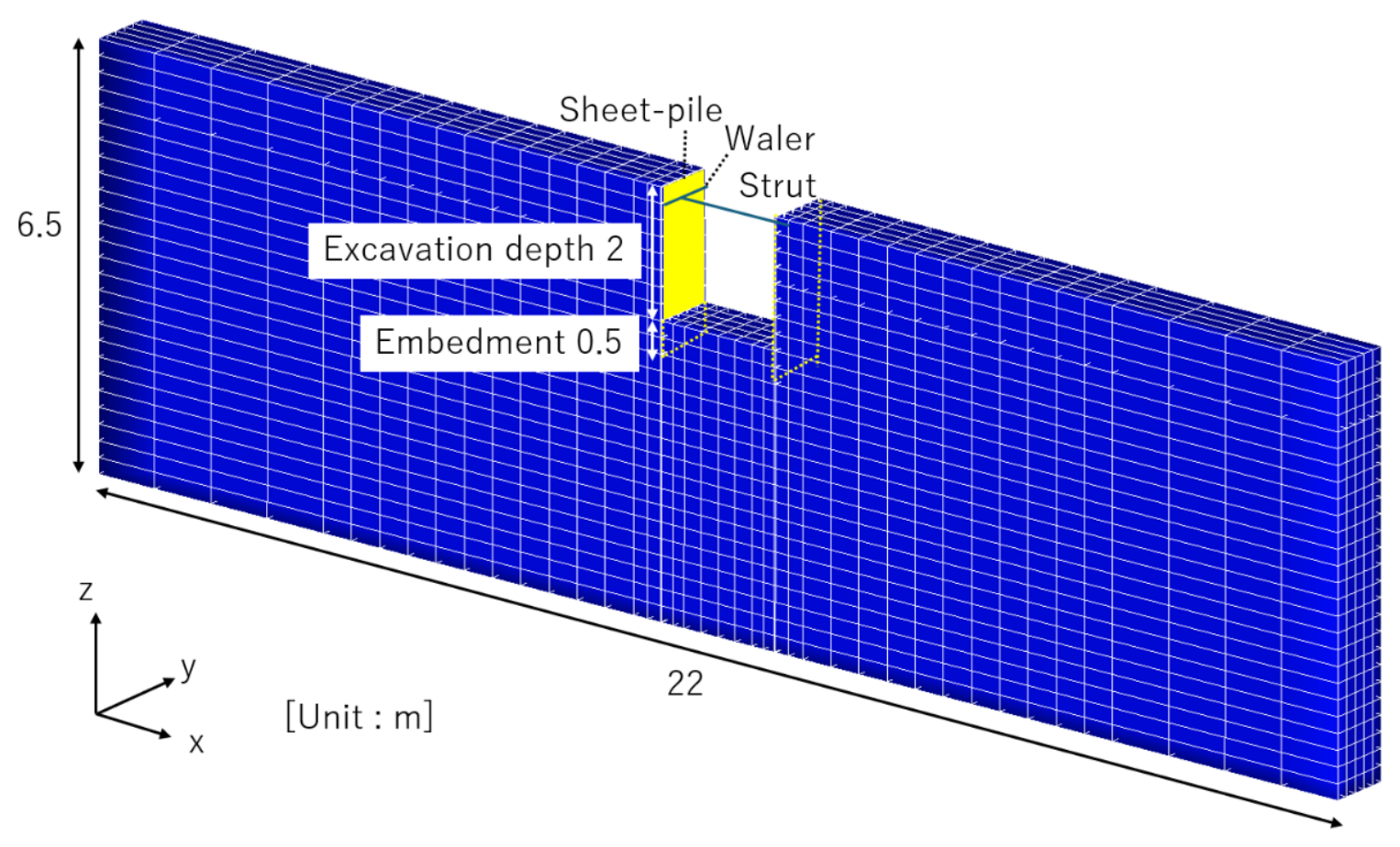
The numerical model is shown in Figure 1 together with the coordinate system. The ground domain extends 22 m in the x-direction, 2 m in the y-direction, and 6.5 m in the z-direction, with an excavation of 2 m in depth and 2 m in width assumed at the center. The analysis model was discretized with tetrahedral elements, consisting of 4339 nodes and 2088 elements.
Figure 1.
Numerical model for excavation analysis.
Retaining walls are installed on both sides of the excavation. Each retaining wall is assumed to be a commonly used type of lightweight sheet-pile (NADS-4.0). The retaining wall was modeled as a plate element, and the plate thickness was adjusted to match the second moment of area of the actual sheet-pile. Walers are installed 0.5 m below the top of the walls along the y-direction, and struts are installed along the x-direction at y = 1.0 m to support the walers. The struts were 2 m in length, and both ends of each strut were rigidly connected to the walers. Groundwater and surcharge loads are not considered in this analysis.
The excavation analysis consisted of two calculation steps. In the first step, the initial ground stress state was generated without the retaining structure. In the second step, the retaining wall and supporting members were activated, and the excavation was performed simultaneously to the target depth.
3.1.2. Material
The material properties of the soil and structural components (lightweight sheet-piles, struts, and walers) are summarized in Table 2 [18]. The soil was modeled as a linear elastic body, and its shear strength was evaluated using the Mohr–Coulomb failure criterion. The Mohr–Coulomb model was adopted because the primary objective of this study was not to reproduce the detailed stress–strain behavior of a specific soil, but to systematically isolate and compare the effects of cohesion and internal friction angle on the internal forces of the supporting members. The relatively simple formulation of this model and its limited number of required input parameters allow the effects of cohesion and internal friction angle to be evaluated directly and consistently over a wide range of parametric cases. For example, although the more advanced Hardening Soil model can represent stress-dependent stiffness and nonlinear soil behavior more realistically, it requires additional parameters describing soil stiffness under triaxial loading, one-dimensional compression, and unloading–reloading conditions. However, reliable values for these parameters were not available for all of the hypothetical soil conditions considered in this study. Assigning assumed values to these parameters could introduce additional uncertainty and obscure the individual effects of cohesion and internal friction angle. Therefore, the Mohr–Coulomb model was considered appropriate for the present comparative parametric investigation. Additionally, in the case of moist sand, apparent cohesion develops due to suction, and this effect is represented in the analysis by assigning a value of c. However, it is difficult to quantitatively evaluate the apparent cohesion induced by suction in actual ground conditions; therefore, although a value of C was assigned in the analysis, it cannot be directly related to soil properties, particularly water content. As described above, the inability of the Mohr–Coulomb model to represent strain-dependent stiffness, stress-dependent stiffness, detailed nonlinear soil behavior, and suction effects accurately is acknowledged as one of the limitations of this study.
Table 2.
Material properties.
The sheet-piles, struts, and walers were also represented as linear elastic elements, and material yielding was not considered in the analysis. The bending stiffness was 101.5 kN·m2. The sheet-piles were modeled using plate elements consisting of 48 elements for one sheet-pile, while the struts and walers were modeled as single beam elements. The struts were attached to the sheet-piles, and the struts and walers were rigidly connected. Interface elements were introduced between the sheet-piles and the surrounding soil to account for soil–structure interaction. No interaction forces were assumed between the ground and the struts or walers.
3.1.3. Boundary Condition
Taking symmetry considerations into account, fixed boundary conditions were assigned at the locations of the side nodes in the x-direction, at x = 0 m and x = 22 m. In the y-direction, fixed boundary conditions were assigned at the locations of the side nodes at y = 0 m and 2 m. These boundary conditions were set so that each model side surface satisfied displacement symmetry conditions. The bottom nodes were fixed in all directions.
3.1.4. Numerical Case
A parametric study was conducted by varying the soil properties, namely cohesion C from 0 to 40 kN/m2 and internal friction angle f from 10° to 40°, with reference to the soil classification and corresponding combinations shown in Table 3 [19]. Strictly speaking, the elastic modulus and unit weight of the soil should vary depending on the soil type; however, in this study, unified values were adopted. Therefore, these combinations of material properties are intended for a parametric investigation and do not necessarily represent actual field soil conditions. The analysis cases are described as “Case C-ϕ.” For example, Case 0–30 represents soil properties with a cohesion of 0 kN/m2 and an internal friction angle of 30°.
Table 3.
Soil types corresponding to combinations of cohesion and internal friction angle.
3.2. Numerical Result
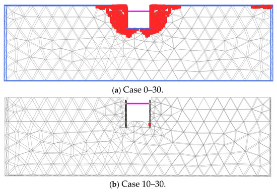
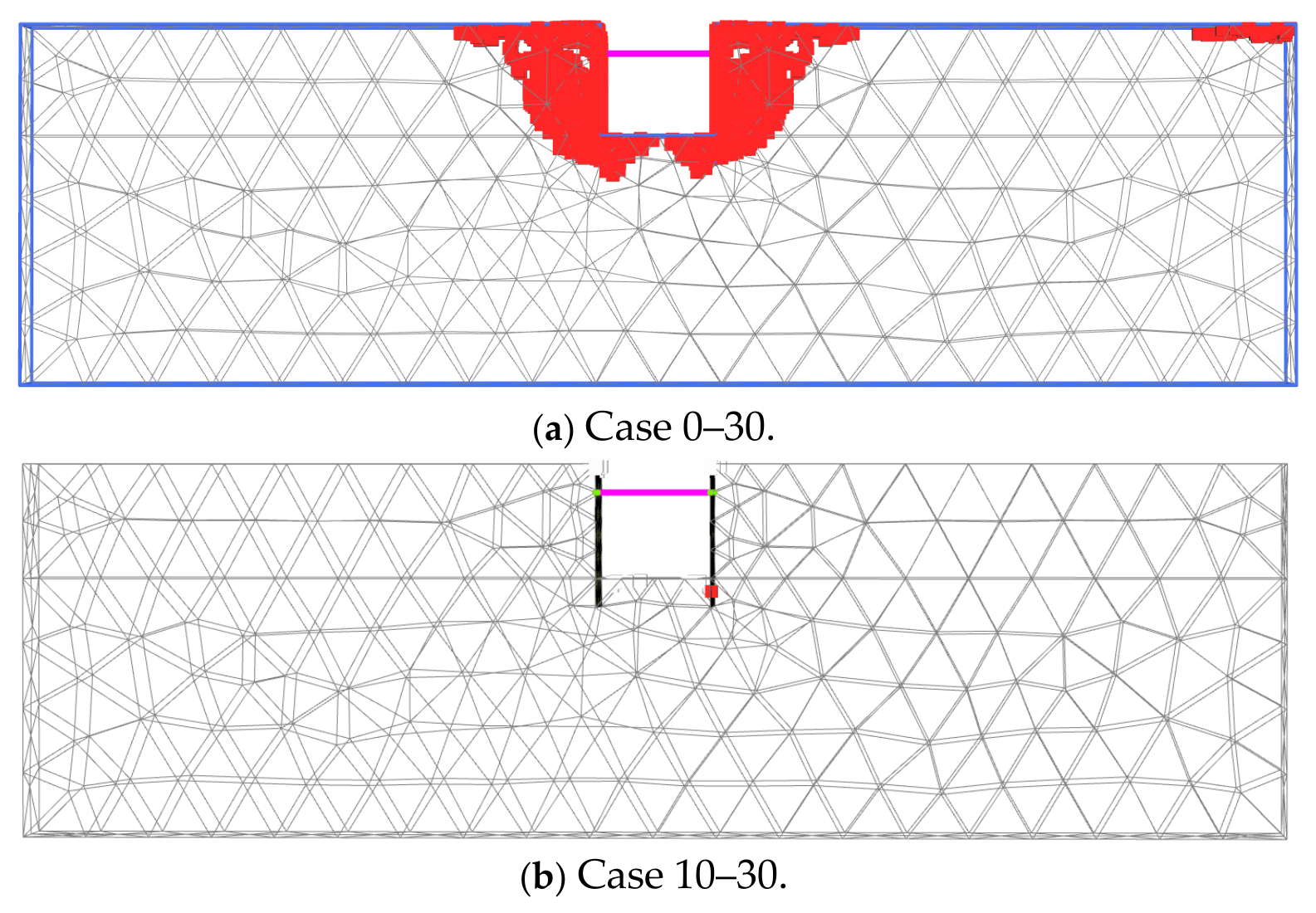
Figure 2 shows the deformation diagrams obtained from the excavation analysis. Figure 2a,b correspond to Case 0–30 and Case 10–30, respectively. Figure 2 also indicates the failure zones. In Case 0–30, wedge-shaped failure zones were observed behind the sheet-piles, indicating that earth pressure acted on the sheet-piles due to shear failure of the backfill ground. In contrast, in Case 10–30, the failure zones disappeared, suggesting that the earth pressure acting on the sheet-piles was small.
Figure 2.
Ground deformation and failure zones after excavation.
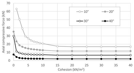
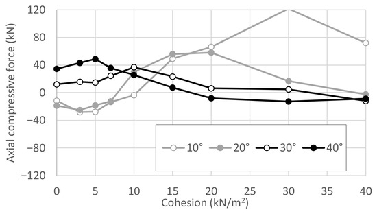
For all cases, the compressive axial force in the struts is summarized in Figure 3. The struts are subjected to compressive forces due to earth pressure acting from both sides. The results showed that the axial force in the struts decreased as the cohesion increased.
Figure 3.
Compressive axial forces in the struts for all cases.
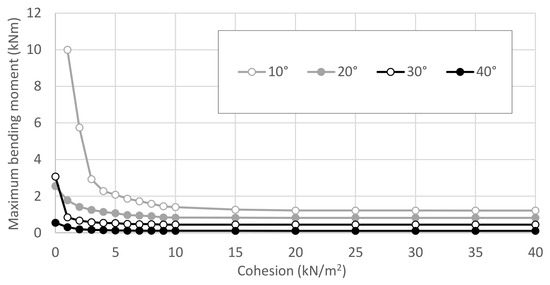
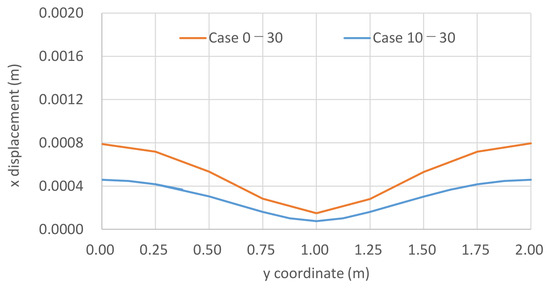
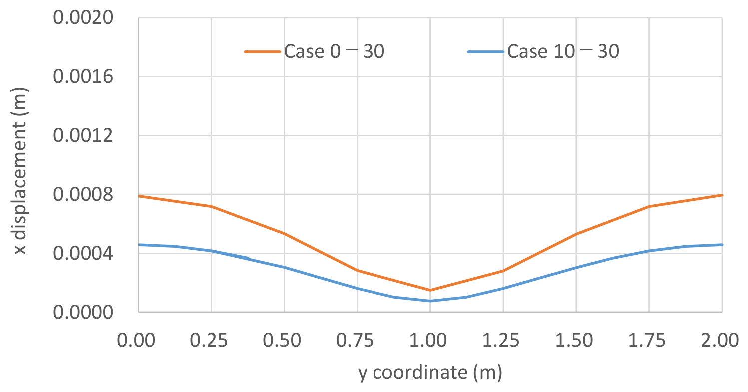
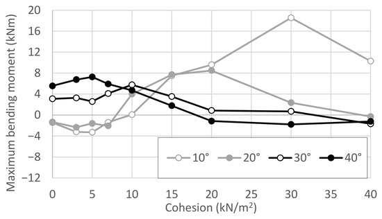
The bending moment at the center of the waler is summarized in Figure 4. Because the struts and walers are structurally connected, the axial forces in the struts and the bending moments in the walers exhibited similar trends. The deformation of the waler is presented in Figure 5 for Cases 0–30 and 10–30, as representative cases. The waler deformed in bending with the connection point to the strut acting as a support, and the maximum bending moment occurred at the supports (y = 1 m). Additionally, the smaller the internal friction angle, the larger the earth pressure, resulting in greater deformation of the walers.
Figure 4.
Maximum bending moments of the walers for all cases.
Figure 5.
Deformation of the left waler after excavation.
From Figure 3 and Figure 4, it can be seen that when C ≤ 10 kN/m2, the member forces were highly sensitive to changes in cohesion, whereas when C ≥ 10 kN/m2, the member forces showed little variation. This is consistent with the observation that, while several failure zones were identified in the lower back of the sheet-piles in Figure 2a, these zones disappeared when the cohesion exceeded 10 kN/m2, as shown in Figure 2b.
Tatsuoka [20] proposed the critical self-standing height of soil based on the Mohr–Coulomb failure criterion, as expressed in Equation (1). Substituting the ground conditions here gives a cohesion of 10.2 kN/m2. In other words, at C = 10 kN/m2, the ground is already nearly self-standing, and further increases in c do not affect the member forces, which was also confirmed from Equation (1):
where Hc is the critical height (m), C is the cohesion (kN/m2), γ is the unit weight (kN/m3), and Ka is the active earth pressure coefficient.
4. Dynamic Analysis
In order to examine the structural member forces during a subsequent earthquake, a dynamic analysis was carried out using the finite-element program LIQCA 3D. Although LIQCA 3D was originally developed for analyzing liquefaction phenomena, it is also an effective analysis tool for ground conditions where liquefaction does not occur.
4.1. Numerical Condition
4.1.1. Model
Since the dimensions, boundary conditions, and other basic settings are essentially the same as in the previous chapter, only the differences are described here. The present model consists of prismatic (hexahedral) elements, with 5411 nodes and 6966 elements shown in Figure 6. The soil was modeled as an elastic–perfectly plastic body, while the struts and walers were represented by beam elements, the same as in the excavation analysis. The sheet-piles were modeled using solid elements with a thickness of 20 mm (I = 6.67 × 10⁻⁷ m4). The Young’s modulus was set to 1.52 × 10⁸ kN/m2, resulting in a bending stiffness of 101.5 kN·m2, equivalent to that of the actual sheet-piles and consistent with the value adopted in the PLAXIS analysis described in the previous section. The analysis procedure consisted of a self-weight analysis under the excavated condition, followed by a dynamic analysis with applied shaking.
Figure 6.
Numerical model for dynamic analysis.
4.1.2. Additional Case
In addition to the excavation analysis cases, one case for saturated ground was included. For the saturated ground, the groundwater table was assumed to be at the ground surface, and the soil parameters are listed in Table 4 [21,22]. The ground was assumed to be saturated medium-dense sand with C = 0 kN/m2, ϕ = 30°, and Dr = 40%, and a cyclic elasto-plastic model for sand was applied [21,22]. This case is referred to as Case 0–30′.
Table 4.
Soil parameters for Case 0–30′.
4.1.3. Input Motion
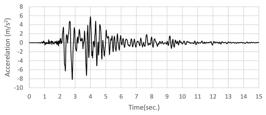
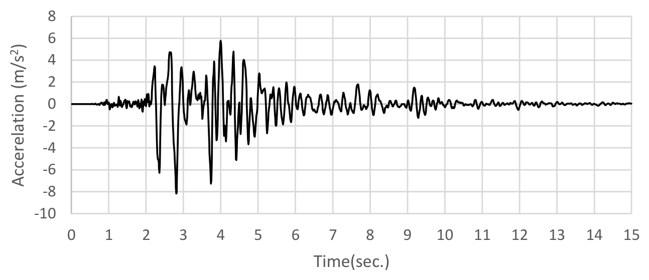
The input motion in the x-direction was a wave with a maximum acceleration of 8.18 m/s2 and a duration of 15 s, as represented by the plot shown in Figure 7 [23]. The input motion was based on a seismic waveform recorded during the 1995 Great Hanshin Earthquake in Japan. The Newmark method was used to solve for the responses of the soil and the structure. An incremental time interval of 0.001 s was adopted to ensure numerical stability and accuracy in the dynamic analysis. The Newmark integration parameters were set to β = 0.3025 and γ = 0.6, which are commonly used values providing unconditional stability and numerical damping of high-frequency responses. A stiffness-proportional Rayleigh damping coefficient of 0.003 was employed, following typical practice in LIQCA-based seismic response analyses. These values were adopted based on the LIQCA user manual [24] and have also been employed in previous studies, such as Refs. [21,22].
Figure 7.
Input motion.
4.2. Numerical Result
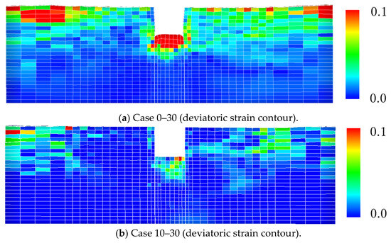
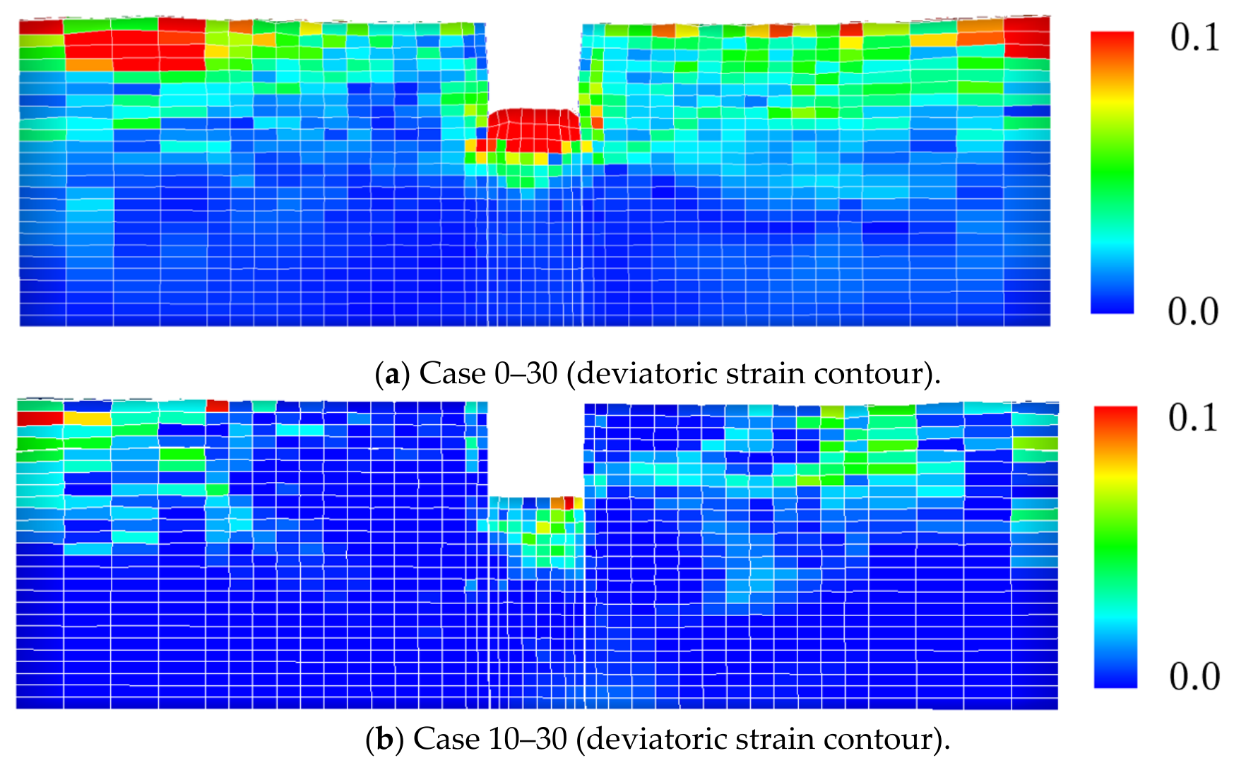
Figure 8 shows the deformation diagrams at the end of shaking (t = 15 s). Figure 8a,b present the deviatoric strain distributions for Cases 0–30 and 10–30, respectively. Figure 9 and Figure 10 show the axial forces in the struts and the maximum bending moments in the walers at the end of shaking (t = 15 s) for Case 0–30 and Case 10–30. The member forces at the onset of shaking were taken as zero.
Figure 8.
Deviatoric strain distributions for Cases 0–30 and 10–30.
Figure 9.
Compressive axial forces of the struts for all cases.
Figure 10.
Maximum bending moments of the walers for all cases.
In Figure 8a, where the cohesion is 0 kN/m2, the ground strength at the excavation face was very low, and strains developed around the excavation face. This suggests that the excavation tended to bulge upward and expand laterally on both sides. As a result, as shown in Figure 9, a compressive force of 12.1 kN developed in the strut. In contrast, in Figure 8b, where the cohesion is 10 kN/m2, such deformation around the excavation face was not evident. As shown in Figure 9, a compressive force of 37.1 kN developed in the strut.
Compared with Case 10–30, the compressive force in the strut was smaller in Case 0–30. In general, higher cohesion reduces the earth pressure acting on the sheet-piles, resulting in a smaller compressive force in the strut. However, in Case 0–30, because the strength at the excavation face was low, the ground deformed outward toward the excavation side. This deformation is considered to have reduced the compressive force in the strut.
As described above, different phenomena occur depending on the magnitudes of cohesion and internal friction angle. These effects interact in a complex manner, and as a result, the axial forces in the struts and the bending moments in the walers cannot be represented by a single consistent trend, as shown in Figure 9 and Figure 10.
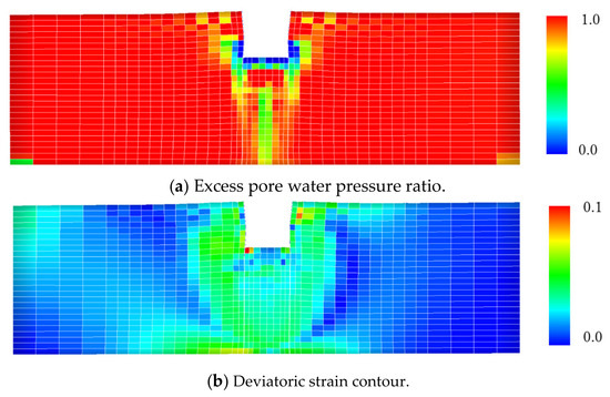
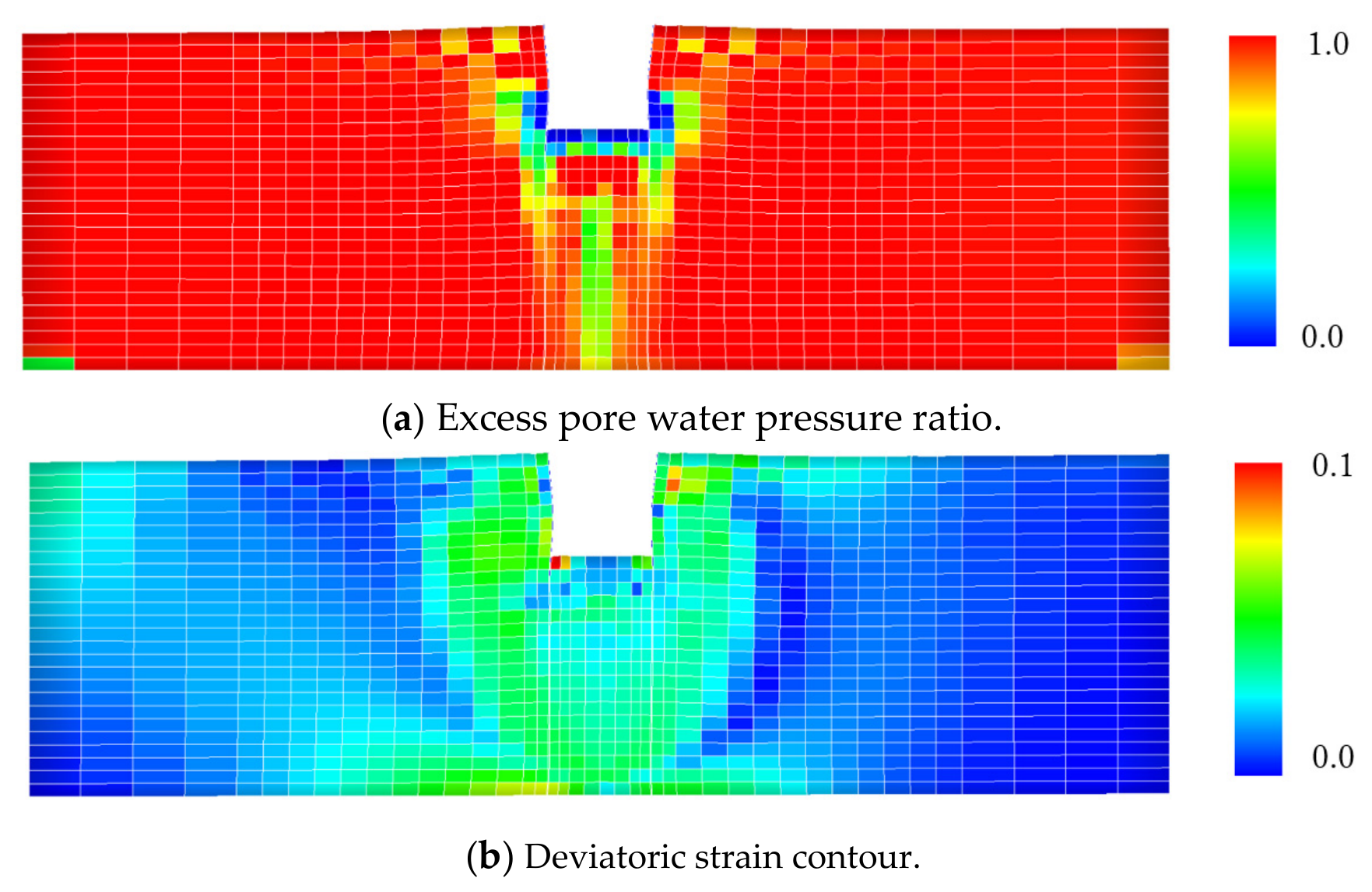
Figure 11a,b show the contour plots of the excess pore water pressure ratio and the deviatoric strain for Case 0–30′ at the end of shaking (t = 15 s), respectively. Figure 11a clearly demonstrates that the ground has undergone full liquefaction. Figure 11b shows that strains develop around the excavation face, and that the excavation face moves upward.
Figure 11.
The deformation diagrams (Case 0–30′).
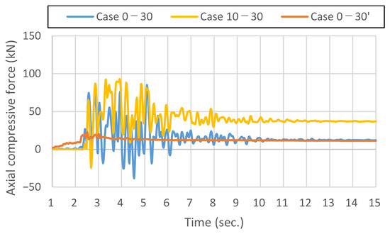
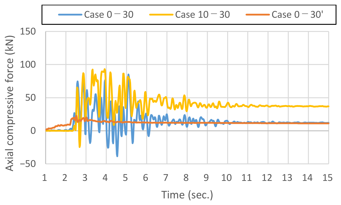
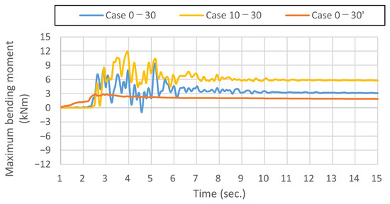
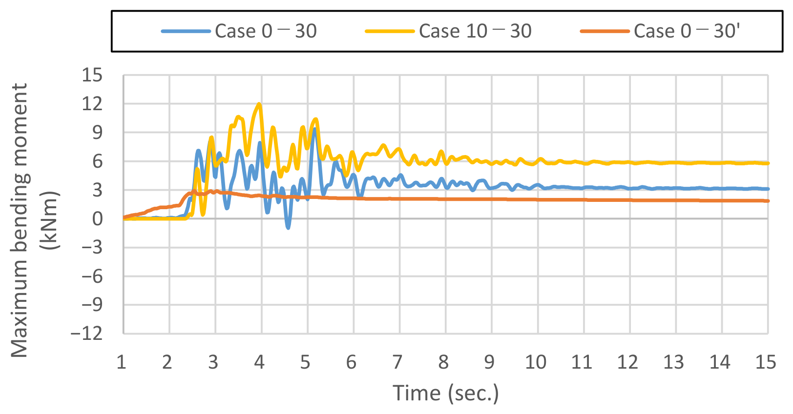
Figure 12 and Figure 13 show the time histories of the axial forces in the struts and the maximum bending moments in the walers for Case 0–30, Case 10–30, and Case 0–30′. The member forces at the onset of shaking were taken as zero. In Figure 12, compressive forces increased in Case 0–30 and Case 10–30. During the shaking, the compressive force in the strut was larger in Case 10–30 than in Case 0–30, which is consistent with the behavior shown in Figure 9. Figure 12 and Figure 13 also include the results of Case 0–30′. The residual member forces were nearly the same as those in Case 0–30. However, the vibration component during shaking was smaller in Case 0–30′ than in Case 0–30. This suggests that liquefaction of the ground induced a vibration-isolation effect, thereby reducing the loads acting on the sheet-piles. A comparison of Figure 12 and Figure 13 indicates that, because the struts and walers were rigidly connected, the development of internal forces in both members exhibited similar behavior for all cases.
Figure 12.
The time histories of the axial forces in the struts.
Figure 13.
The time histories of the maximum bending moment in the walers.
5. Limitations of the Present Study
The findings obtained in this study should be interpreted within the scope of the assumptions adopted in the numerical analyses. The limitations of this study are described below.
- (1)
- Excavation analysis
In the excavation analyses, the Mohr–Coulomb model was adopted to systematically evaluate the effects of cohesion and internal friction angle. Therefore, strain-dependent stiffness, stress-dependent stiffness, detailed nonlinear soil behavior, and suction effects were not accurately represented. In addition, cohesion and internal friction angle were varied, while unified values were adopted for other soil properties, such as Young’s modulus and unit weight. Therefore, the combinations of soil properties considered in this study do not necessarily represent actual field soil conditions.
- (2)
- Dynamic analysis
Only one input ground motion was used in the dynamic analyses. Therefore, it remains unclear whether the conclusions of this study are applicable to earthquake motions with different peak accelerations, durations, and predominant frequencies. In addition, although one saturated-ground case was considered to investigate liquefaction-induced behavior, the effects of differences in groundwater conditions, relative density, and liquefaction characteristics were not systematically examined.
- (3)
- Other limitations
In both the excavation and dynamic analyses, the structural members were assumed to behave elastically, and their plastic behavior under large loading conditions was not considered. In addition, simplified geometric, structural, and material conditions were adopted in the analyses. The threshold values and trends in member forces obtained in this study depend on the adopted excavation geometry, structural configuration, and material properties and should not be directly regarded as universal design criteria.
6. Conclusions
This study focused on the supporting members used in braced double sheet-pile walls and investigated, through finite-element analyses, how differences in soil properties influence the forces acting on these members. The main findings are summarized below.
- (1)
- Excavation analysis
The excavation analyses using PLAXIS 3D showed that decreases in soil strength, represented by cohesion and internal friction angle, increased the demand on the supporting members and resulted in larger internal forces. Because the struts and walers were structurally connected, their internal forces exhibited similar trends. When the soil cohesion exceeded approximately 10 kN/m2, the member forces remained relatively small and showed little variation with further increases in cohesion. This occurred because the ground surrounding the 2 m-deep excavation experienced little failure at this cohesion level.
- (2)
- Dynamic analysis
The dynamic analyses using LIQCA 3D revealed complex interactions between the earth pressure acting on the retaining walls and the deformation of the excavation face. Earth pressure generated compressive forces in the struts, whereas lateral expansion of the excavation face reduced the strut axial forces. The relative contributions of these mechanisms varied depending on the cohesion and internal friction angle. In particular, the reduction in the strut axial forces under zero-cohesion conditions may increase the risk of disengagement when push-type struts are used and therefore requires particular attention. In the dry-ground cases, large vibration components were observed in the strut forces during shaking. In contrast, liquefaction occurred in the saturated-ground case and produced a vibration-isolation effect, resulting in substantially smaller vibration components.
- (3)
- Engineering significance and applicability limitations
The results of this study can identify ground conditions under which large member forces may develop in small-scale excavations and provide fundamental information for preliminarily assessing the need for detailed numerical analyses or additional reinforcement. However, the findings should be interpreted within the range of the excavation geometry, structural configuration, soil properties, and loading conditions adopted in the analyses. In particular, the threshold values and trends in member forces obtained in this study should not be directly regarded as universal design criteria. Future work will include model tests and full-scale experiments to validate the numerical results, with particular emphasis on weak ground conditions under which large member forces were obtained.
Funding
This research received no external funding.
Institutional Review Board Statement
Not applicable.
Informed Consent Statement
Not applicable.
Data Availability Statement
The data supporting the findings of this study are available from the author upon reasonable request.
Conflicts of Interest
The author declares no conflicts of interest.
References
- Finno, R.J.; Harahap, I.S. Finite element analyses of HDR-4 excavation. J. Geotech. Eng. 1991, 117, 1590–1609. [Google Scholar] [CrossRef] [Scilit]
- Finno, R.J.; Harahap, I.S.; Sabatini, P.J. Analysis of braced excavations with coupled finite element formulations. Comput. Geotech. 1991, 12, 91–114. [Google Scholar] [CrossRef] [Scilit]
- Toyosawa, Y.; Horii, N.; Tamura, S. Failure Characteristics of Sheet Pile Wall in Centrifuge Test; NIIS-RR-94; Research Reports of the National Institute of Industrial Safety: Ulsan, Republic of Korea, 1995; pp. 53–62.
- Karlsrud, K.; Andresen, L. Loads on braced excavations in soft clay. Int. J. Geomech. 2005, 5, 107–113. [Google Scholar] [CrossRef] [Scilit]
- Wang, Z.W.; Ng, C.W.W.; Liu, G.B. Characteristics of wall deflections and ground surface settlements in Shanghai. Can. Geotech. J. 2005, 42, 1243–1254. [Google Scholar] [CrossRef] [Scilit]
- Nakai, T.; Farias, M.M.; Bastos, D.; Sato, Y. Simulation of conventional and inverted braced excavations using subloading tij model. Soils Found. 2007, 47, 597–612. [Google Scholar] [CrossRef] [Scilit]
- Bose, S.K.; Som, N.N. Parametric study of a braced cut by finite element method. Comput. Geotech. 1998, 22, 91–107. [Google Scholar] [CrossRef] [Scilit]
- Yun, J.S.; Park, S.J.; Falcon, S.S.; Han, J.-T.; Kim, D.; Choo, Y.W. Seismic response of braced excavation wall supporting deep sand layer using dynamic centrifuge tests. Soil Dyn. Earthq. Eng. 2024, 183, 108782. [Google Scholar] [CrossRef] [Scilit]
- Konai, S.; Sengupta, A.; Deb, K. Behavior of braced wall embedded in saturated liquefiable sand under seismic loading. Earthq. Eng. Eng. Vib. 2021, 20, 361–375. [Google Scholar] [CrossRef] [Scilit]
- Konai, S.; Sengupta, A.; Deb, K. Behavior of braced excavation in sand under a seismic condition: Experimental and numerical studies. Earthq. Eng. Eng. Vib. 2018, 17, 311–324. [Google Scholar] [CrossRef] [Scilit]
- Konai, S.; Sengupta, A.; Deb, K. Seismic behavior of cantilever wall embedded in dry and saturated sand. Front. Struct. Civ. Eng. 2020, 14, 690–705. [Google Scholar] [CrossRef] [Scilit]
- Fujiwara, K. Numerical analysis of small-scale earth retaining structures during liquefaction. GEOMATE J. 2026, 30, 77–85. [Google Scholar] [CrossRef] [Scilit]
- Yan, B.; Fujiwara, K. Study on Small-Scale Excavation Focusing on the Cohesion of Sand. In Proceedings of the 60th Japan National Conference on Geotechnical Engineering; Paper No. 23-6-2-01; Japanese Geotechnical Society: Tokyo, Japan, 2025. (In Japanese) [Google Scholar]
- Oka, F.; Yashima, A.; Shibata, T.; Kato, M.; Uzuoka, R. FEM-FDM coupled liquefaction analysis of a porous soil using an elasto-plastic model. Appl. Sci. Res. 1994, 52, 209–245. [Google Scholar] [CrossRef] [Scilit]
- Oka, F.; Yashima, A.; Tateishi, A.; Taguchi, Y.; Yamashita, A. A cyclic elasto-plastic constitutive model for sand considering a plastic-strain dependence of the shear modulus. Géotechnique 1999, 49, 661–680. [Google Scholar] [CrossRef] [Scilit]
- Biot, M.A. Mechanics of deformation and acoustic propagation in porous media. J. Appl. Phys. 1962, 33, 1482–1498. [Google Scholar] [CrossRef] [Scilit]
- Fujiwara, K.; Taenaka, S.; Otsushi, K.; Yashima, A.; Sawada, K.; Hara, T.; Ogawa, T.; Takeda, K. Study on coastal levee reinforcement using double sheet-piles with partition walls. Int. J. Offshore Polar Eng. 2017, 27, 310–317. [Google Scholar] [CrossRef] [Scilit]
- Hoshin Co., Ltd. Available online: https://hoshin.co.jp/products/dodome/ (accessed on 5 May 2026).
- Bowles, J.E. Foundation Analysis and Design, 5th ed.; McGraw-Hill: New York, NY, USA, 1996. [Google Scholar]
- Tatsuoka, F. Earth pressure in the presence of soil cohesion. Kiso-Ko (Found. Eng.) 2011, 39, 98–101. [Google Scholar]
- Fujiwara, K.; Kobori, Y.; Yashima, A.; Sawada, K.; Taenaka, S.; Otsushi, K.; Toda, K. Study on reinforcement effect of double sheet-pile wall installed in dyke as the countermeasure against large scale earthquake. Jpn. Geotech. J. 2017, 12, 109–122. [Google Scholar] [CrossRef] [Scilit]
- Fujiwara, K.; Ogawa, N.; Nakai, K. 3-D numerical analysis of partial floating sheet-pile method as countermeasure for liquefaction. J. JSCE 2021, 9, 138–147. [Google Scholar] [CrossRef] [Scilit] [PubMed]
- National Research Institute for Earth Science and Disaster Resilience. Strong-Motion Seismograph Networks (K-NET, KiK-net). Available online: https://www.kyoshin.bosai.go.jp (accessed on 29 August 2025).
- LIQCA Liquefaction Geo Research Institute (LIQCARI). LIQCA2D24 and LIQCA3D24 (2024 Release Edition) Materials, Part III: Manual; LIQCA Liquefaction Geo Research Institute (LIQCARI): Osaka, Japan, 2024. (In Japanese) [Google Scholar]

Disclaimer/Publisher’s Note: The statements, opinions and data contained in all publications are solely those of the individual author(s) and contributor(s) and not of MDPI and/or the editor(s). MDPI and/or the editor(s) disclaim responsibility for any injury to people or property resulting from any ideas, methods, instructions or products referred to in the content. |
© 2026 by the author. Licensee MDPI, Basel, Switzerland. This article is an open access article distributed under the terms and conditions of the Creative Commons Attribution (CC BY) license.