Article

Innovative Surface Treatment Techniques for Carbon Fiber-Based Polymer Matrix Composites

1
Structural Design Engineering, Turkish Aerospace, Ankara 06980, Türkiye
2
Department of Mechanical Engineering, Graduate School of Natural and Applied Sciences, Gazi University, Ankara 06570, Türkiye
3
Department of Mechanical Engineering, Izmir Institute of Technology, Izmir 35430, Türkiye
*
Author to whom correspondence should be addressed.
Solids 2026, 7(1), 11; https://doi.org/10.3390/solids7010011
Submission received: 31 December 2025 / Revised: 30 January 2026 / Accepted: 5 February 2026 / Published: 9 February 2026
(This article belongs to the Special Issue Young Talents in Solid-State Sciences)

Abstract

Adhesive bonding has emerged as a promising technology for joining carbon fiber reinforced polymer (CFRP) structures in aircraft, offering advantages over traditional mechanical fastening such as weight reduction and uniform stress distribution. This study evaluates the effectiveness of innovative laser ablation and electrospinning surface treatments compared to the conventional peel-ply method for secondary bonding. Surface features and wetting behavior were characterized using scanning electron microscopy (SEM) and contact angle measurements, while mechanical performance was assessed via single lap shear tests. Results demonstrate that laser ablation (30 W power, 10 m/s speed) achieved the highest bond strength at 20.68 MPa, followed by electrospinning (18.20 MPa) using 10 wt% PA-66 nanofibers. Both advanced techniques significantly outperformed the peel-ply method, which yielded the lowest shear strength of 15.18 MPa. SEM analysis confirmed that laser treatment facilitated direct fiber exposure with minimal damage, while nanofibers provided enhanced physical interlocking. In conclusion, laser ablation proved to be the most effective technique for enhancing interfacial bonding in aerospace-grade CFRP structures, followed by electrospinning, offering a superior alternative to traditional surface preparation.

1. Introduction

Carbon fiber reinforced polymer (CFRP) composites are widely used in aviation due to their strength-to-weight ratio, fatigue and impact resistance, and high modulus [1,2,3]. While mechanical fastening is commonly used for CFRP assembly, it presents a few disadvantages, such as weight penalty, higher stresses around holes, and high assembly costs. Adhesive bonding has emerged as a favorable alternative, offering a lightweight solution with uniform stress distribution and enhanced structural integrity [4,5]. Nevertheless, the performance of these joints relies on the adhesion between adhesive and substrate, making the surface condition of the CFRP the decisive factor. Before bonding, a clean surface with increased wettability is required to increase the adhesion performance between CFRP and adhesive.
Diverse surface pretreatments are employed to enhance CFRP adhesion [3], typically categorized as chemical or mechanical. Chemical methods like acid etching [4,6,7] are often avoided due to their high environmental damage, lack of automation potential, and the risk of fiber degradation. Mechanical alternatives include peel-ply, grit-blasting, and polishing [2,5]. The disadvantage of the grid blasting treatment method is that it is inevitable to damage the fibers [2,3,4,6,7,8,9,10]. The disadvantage of the peel-ply treatment method is that the outside resin layer prevents the direct connection between the adhesive and the fibers. The peel-ply removal operation is quite critical to clean all contaminants after the peel-ply is removed, not to decrease the bonding performance [3,10]; while polishing [5] provides a cleaned surface for bonding, this method decreases the mechanical interlocking, surface roughness, wettability, and free energy of the surface. Instead, recent studies presented that laser and electrospinning surface treatment methods are good options due to their advantages for industrial applications [11,12,13].
An aspiring alternative is laser surface treatment, which utilizes thermal energy to selectively ablate the polymer matrix [14]. By adjusting the energy levels relative to the material’s irradiation thresholds, specific layers can be evaporated with high precision. For CFRP laminates, this process enhances adhesive bonding by (i) removing inert release agents that prevent adhesion [10,11,12,13,14,15], (ii) cleaning the underlying carbon fiber layers through matrix removal, and (iii) improving the surface’s overall wettability [1,16]. As a result, obtaining a direct attachment to the reinforcement elements is possible while increasing the wettability and removing the contamination on the surface [2,17].
Another promising surface treatment method is electrospinning. In recent years, electrospinning of nanofibers has gained importance in enhancing material properties [18,19,20,21,22]. Coating low-weight thermoplastic nanofiber increased mode I and mode II fracture toughness of carbon fiber/epoxy laminates [23,24]. From the surface treatment perspective, before the bonding process, some studies [25,26,27] reported that the absorption properties of nanofiber coating are quite high. These properties increase wettability by decreasing the contact angle. Also, some studies [18,28] found that bond strength is increased by toughness mechanisms of the bridging effect of nanofibers until optimum coating time.
This work aims to compare laser and electrospinning techniques with optimized parameters as compared to the traditional peel-ply technique. Surface features and wetting behavior were characterized by using the scanning electron microscope (SEM) technique and contact angle measurements. An optimum range for the laser and electrospinning parameters for an appropriately treated CFRP composite surface was determined within the study. A single lap shear test was performed to evaluate the effects of preparation parameters as compared to those with the peel-ply technique.

2. Materials and Methods

2.1. Materials and Specimen Manufacturing

CFRP composite specimens were manufactured with unidirectional HexPly® M91/34%/UD194/IM7-12K material with a stacking sequence ([45/0/ −45/90/ −45/0/45]s) of 14 layers of carbon/epoxy prepregs. This unidirectional (UD) prepreg was preferred in primary aerospace structures with a high-performance and tough epoxy matrix. A secondary bonding method with a three-layer Solvay FM® 300K film adhesive was used to bond the process. Each side of CFRP specimens was manufactured by stacking under a vacuum, followed by a curing stage performed at 180 °C and 7 bar for 2 h with an autoclave technique. The thickness of each ply was 0.184 mm, and the total thickness of the specimen was 2.576 mm. The CFRP lamination lay-up is schematically illustrated in Figure 1.

2.2. Surface Treatment Techniques

Three different surface preparation techniques were evaluated to enhance the bonding performance of the CFRP structures.

2.2.1. Peel Ply Treatment

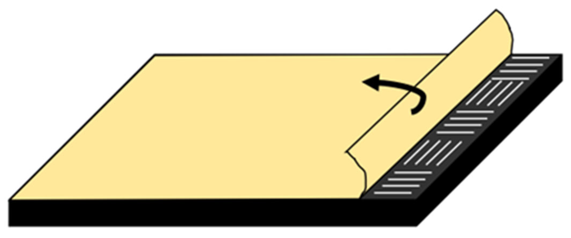
Peel ply is the most common surface preparation technique in the industry. Peel ply is laid on a bonding surface before curing and cured with the structural part. It has been removed before the bonding process. Peel-ply fabrics have different patterns, transferring the same pattern to the liquefied resin top on the structural part. It helps to increase the bonding surface area and protect the bonding interface against environmental effects such as dust and oil until the bonding process starts. The present study uses Hexcel BI9842 polyester fabric as a peel-ply. Figure 2 represents the peel-ply removal from the cured CFRP part before bonding.

2.2.2. Laser Ablation

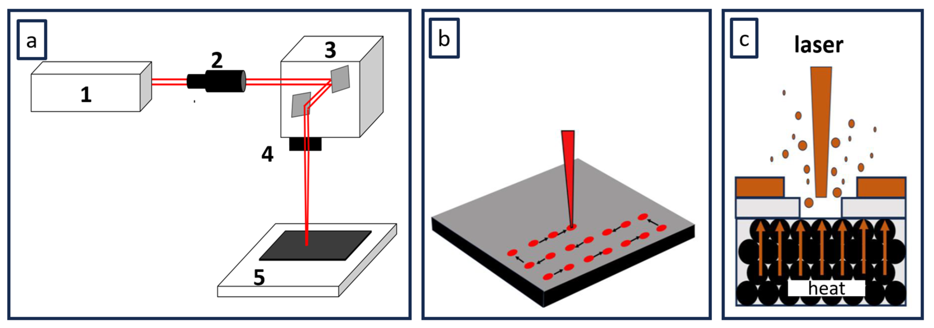
Laser is a promising surface preparation technique that is affected by many parameters. It is quite important to optimize those parameters to obtain the best bonding performance. The primary purpose of laser surface preparation is to reach fibers by ablating the resin from the top surface of the CFRP structure without damaging the carbon fibers underneath. If epoxy ablates completely from the top surface of CFRP, adhesive could directly bind load-carrying fibers to each other. If excess laser power is applied to the surface, fibers are damaged, and the load-carrying capacity of CFRP decreases. In the case where less laser power is applied to the surface, the laser power is not sufficient for complete ablation of the resin, and it does not result in the best structural bonding [29]. As reported in the literature [2,4,6,7,8,9,10,11,13,14,15,16,17,29], the parameters that affect laser efficiency are wavelength (355 nm, 1064 nm, etc.), laser source (excimer, CO2, Yb:YAG, etc.), interaction time (nanosecond, picosecond, femtosecond), number of pulses, laser power, scanning speed, scanning pattern, pulse frequency, hatch distance, laser diameter, etc. The laser treatment was carried out using an IR-Yb (Ytterbium) fiber nanosecond laser (FLAST-NanoMARK-50w) with the following parameters: a wavelength of 1064 nm, a frequency of 100 kHz, a spot diameter of 30 µm, a pulse width of 100 ns, a positioning resolution of 16 bits, and a processing rate of 2.5 m/s. Thirty µm represents the nominal focal spot size, which was determined based on the F-theta scan lens (f = 163 mm) and the input beam diameter according to the manufacturer’s optical specifications. The laser system’s focus was calibrated to ensure consistent energy density on the CFRP surface during the ablation process. The laser system is illustrated in Figure 3a, which represents the components of the laser ablation mechanism (1. Laser Source; 2. Beam Shaping Device; 3. Galvanometer Scanner; 4. Lens; and 5. Specimen). The laser was applied on a surface with single scanning and equal spacing, as shown in Figure 3b.

2.2.3. Electrospinning

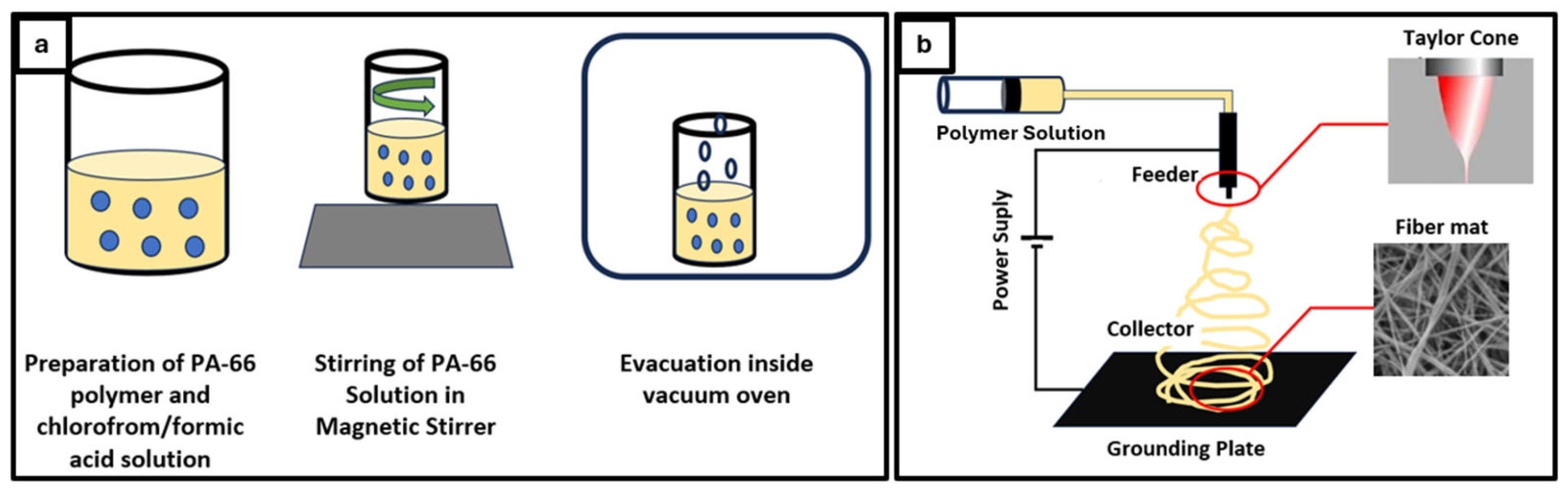
Electrospinning is a method for manufacturing fine polymeric fibers as coating or filtering layers; however, it laid the groundwork for CFRP surface or interface treatment. The working principle of electrospinning involves the formation of continuous thermoplastic nanofibers using an electrical field and a polymer solution and coating the produced fibers on a surface, such as bulk surfaces or technical fabrics. Figure 4b shows a detailed illustration of this principle.
In composite structures, incorporation of electro-spun nanofibers within the interlaminar region provides enhanced interfacial bonding and interlaminar fracture toughness. In this study, PE300TM, Inovenso (Istanbul, Türkiye) was used for the production of the thermoplastic nanofiber coatings on the carbon fiber-based epoxy prepregs. The parameters that affect electrospinning efficiency are the type of polymer, type of solvent, properties of solution (viscosity, conductivity, surface tension), molecular weight, distribution and architecture of polymer, concentration of solution, coating time, electrical field and voltage, feeder geometry (needle, disc, cylinder or spherical), flow rate of polymer solution, distance between feeder and collector, type of current (AC or DC), temperature, moisture, air flow rate, vacuum, etc. Within this study, thermoplastic nanofibers were coated with the following parameters: a flow rate of 20 mL/h (1 mL/h for each nozzle) and an applied voltage of 30 kV were selected, and the distance between the feeder and the collector was set as 12 cm. Polyamide-66 (PA-66) was chosen as a thermoplastic polymer because PA-66 is the most preferred polymer for industrial applications, which has superior properties such as high mechanical strength, high melting temperature, low heat deflection temperature, high processability, exceptional fiber-forming ability, high compatibility with uncured resin, and low moisture absorption capacity for electrospinning. PA-66 was dissolved using a chloroform/formic acid solution. While formic acid dissolves the PA-66 polymer, chloroform changes viscosity for a more homogeneous solution. The preparation of the polymer solution is shown in Figure 4a.
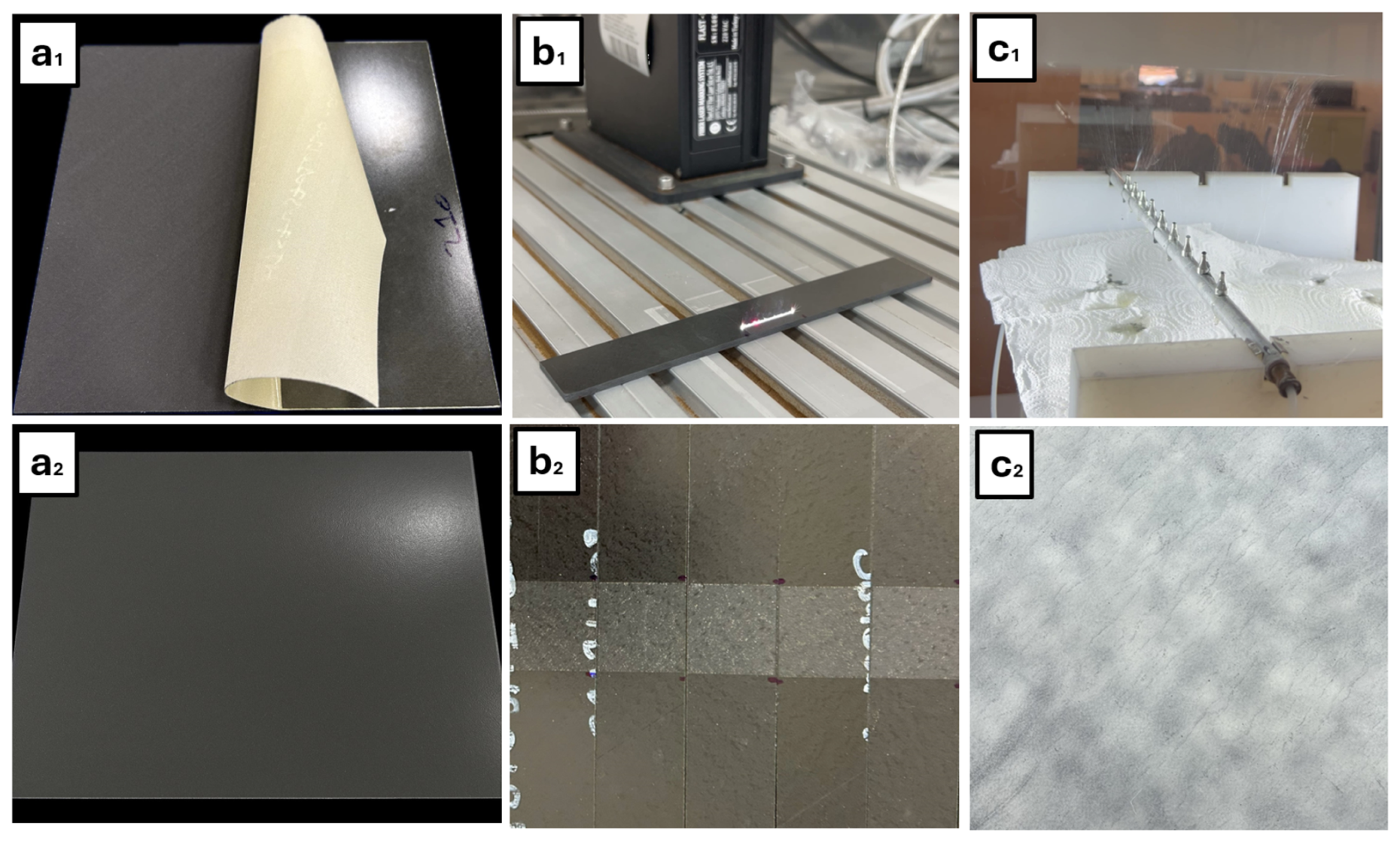
Figure 5 summarizes the three different surface treatment techniques that are investigated in the study. Figure 6 shows some example photos during the processing stages.

2.3. Surface Characterization

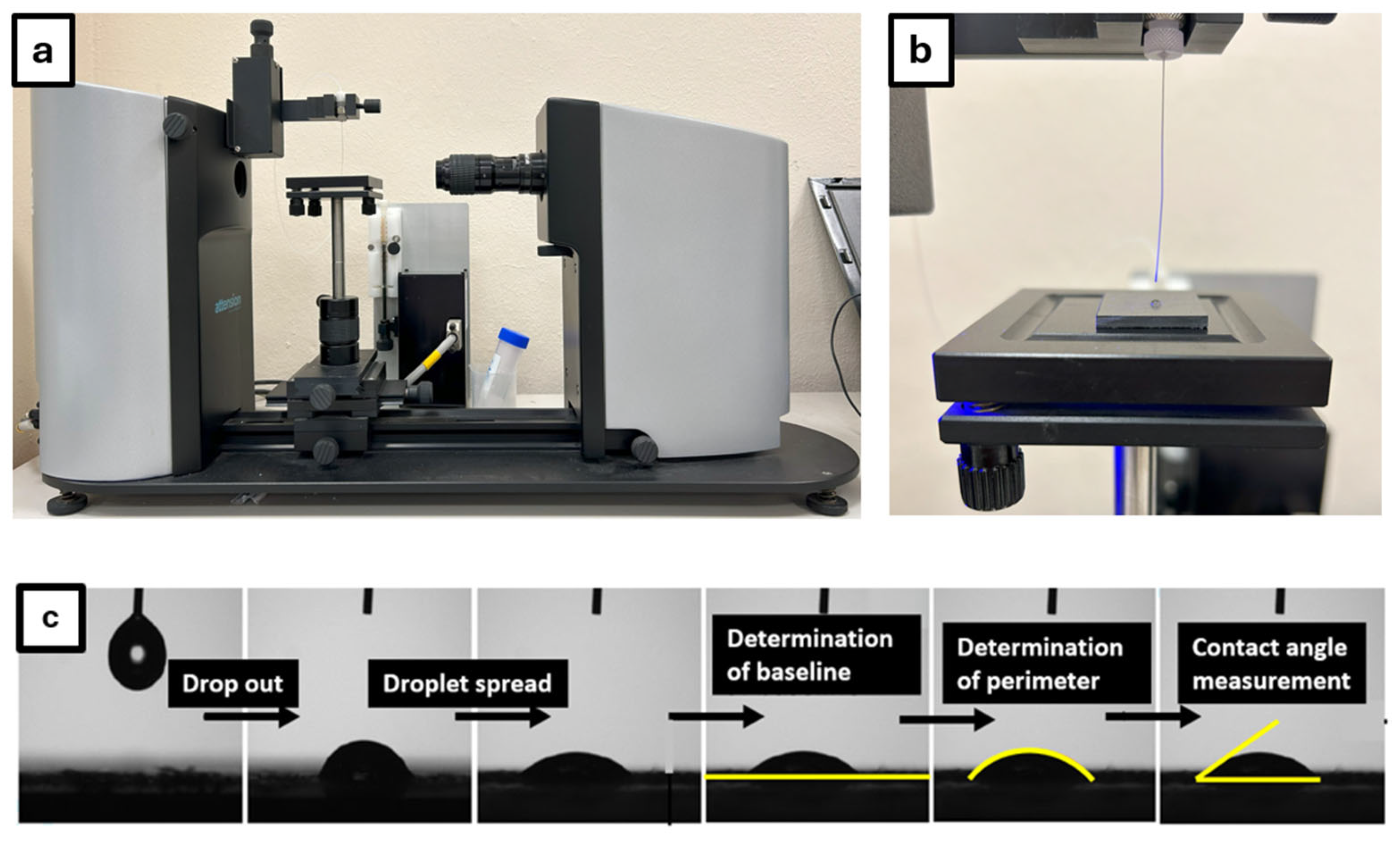
Surface morphology was examined using SEM, while wettability was evaluated through contact angle measurements Theta, Biolin Scientific (Gothenburg, Sweden). As illustrated in Figure 7, the measurement process involved depositing a droplet on the surface and capturing an image after a specific propagation time. The contact angle was then determined by defining the baseline and droplet perimeter, calculating the angle at their point of intersection. In this study, all contact angles were calculated automatically by the software of the contact angle measurement device.

2.4. Parameter Optimization

CFRP structures have inhomogeneous thermal properties because of the difference between the coefficient of thermal conductivity of carbon fiber and epoxy (kEpoxy = 0.1 W/mK and kCarbonFiber = 50 W/mK). Inhomogeneous thermal properties of CFRP cause two different thermal behaviors according to applied laser scanning speed. Most of the laser energy is absorbed by carbon fibers because epoxy is transparent to IR, and this energy is converted into heat and transmitted through the fiber structures during the laser operation. Low scanning speeds induce significant in-plane heat transfer through the carbon fibers, resulting in an extensive heat-affected zone (HAZ) and limited material removal. Conversely, higher scanning speeds restrict this heat dissipation, enabling the thermal energy to selectively remove the epoxy matrix with negligible fiber degradation. This behavior is governed by the thermal conductivity of CFRP; low speeds facilitate heat conduction between consecutive laser spots, whereas higher speeds localize the energy for more efficient ablation. As a result, the applied energy turns more into heat instead of removing the epoxy. Figure 8 shows the heat transfer and ablation mechanism and wettability of surfaces for different laser scanning speeds [29].
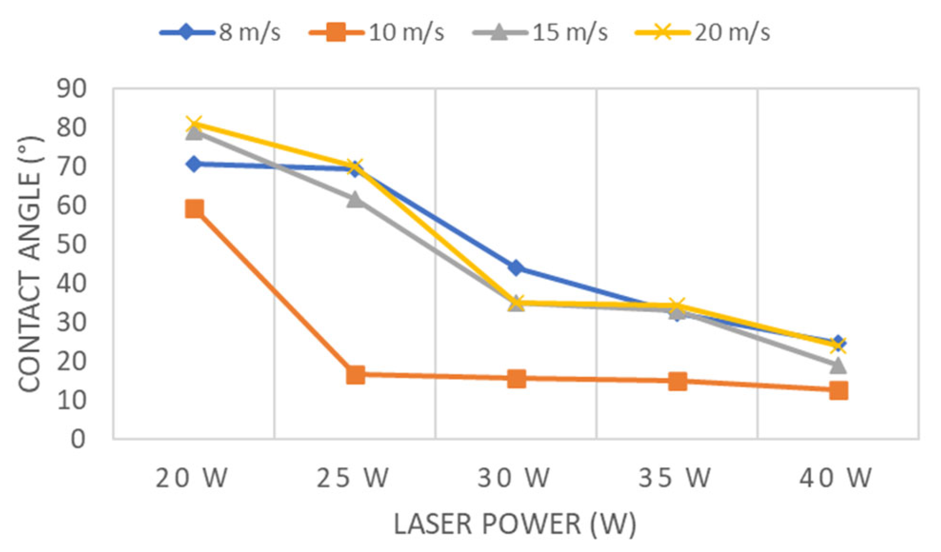
Based on a previous study [29], it was found that 10 m/s laser scanning speed and 30 W laser power parameters are the optimized parameters for the composite system (M91/34%/UD194/IM7-12K), which has the same bonding orientation. This combination gives the best wettability to the surface, which is crucial for bonding. Figure 9 shows the contact angle values for different laser powers and scanning speeds. According to these values, 10 m/s scanning speed is the most suitable for each laser power.
Comparison of contact angle measurement is not adequate to evaluate surface performance before bonding. The main purpose of surface preparation by laser is complete ablation of the epoxy top surface on CFRP to enable adhesive to bind load-carrying fibers directly to each other to obtain the best bonding performance. In the case of partial ablation or complete ablation with damage to fibers, lower contact angles can be observed. This does not imply that the surface is prepared well for bonding. Accordingly, wetting and epoxy ablation should be checked separately. An SEM examination is mandatory to see the presence of residual resin or damaged fiber.
An SEM examination may assist in determining the parameters; for example, it may help in determining which laser power at a 10 m/s scanning speed can ablate the top resin without damaging the fiber. In a previous study [29], the ablation capability of different laser powers has been compared for a 10 m/s scanning speed by SEM images. SEM images for the laser power between 20 W and 40 W are shown in Figure 10. Results show that there are epoxy removals at 20 W and 25 W laser power, which means 20 W and 25 W are not enough for the ablation of the epoxy. The lowest fiber damage was observed at 30 W laser power with totally ablated epoxy, and the highest fiber damage was observed at 40 W laser power. In conclusion, 30 W is the optimum laser power because it can ablate the top resin with minimal or no damage to fibers. Based on a previous study [29] for the same material, scanning speed and fiber orientation on the bonding surface, 30 W laser power has been chosen as the most suitable laser power for 10 m/s in terms of surface cleaning by ablation.
Also, the SEM images for 8 m/s, 10 m/s and 15 m/s laser scanning speeds for 30 W laser power are shown in Figure 11. It can be concluded that while the amount of unablated resin is high at higher speeds, the amount of damaged fibers increases at lower speeds.
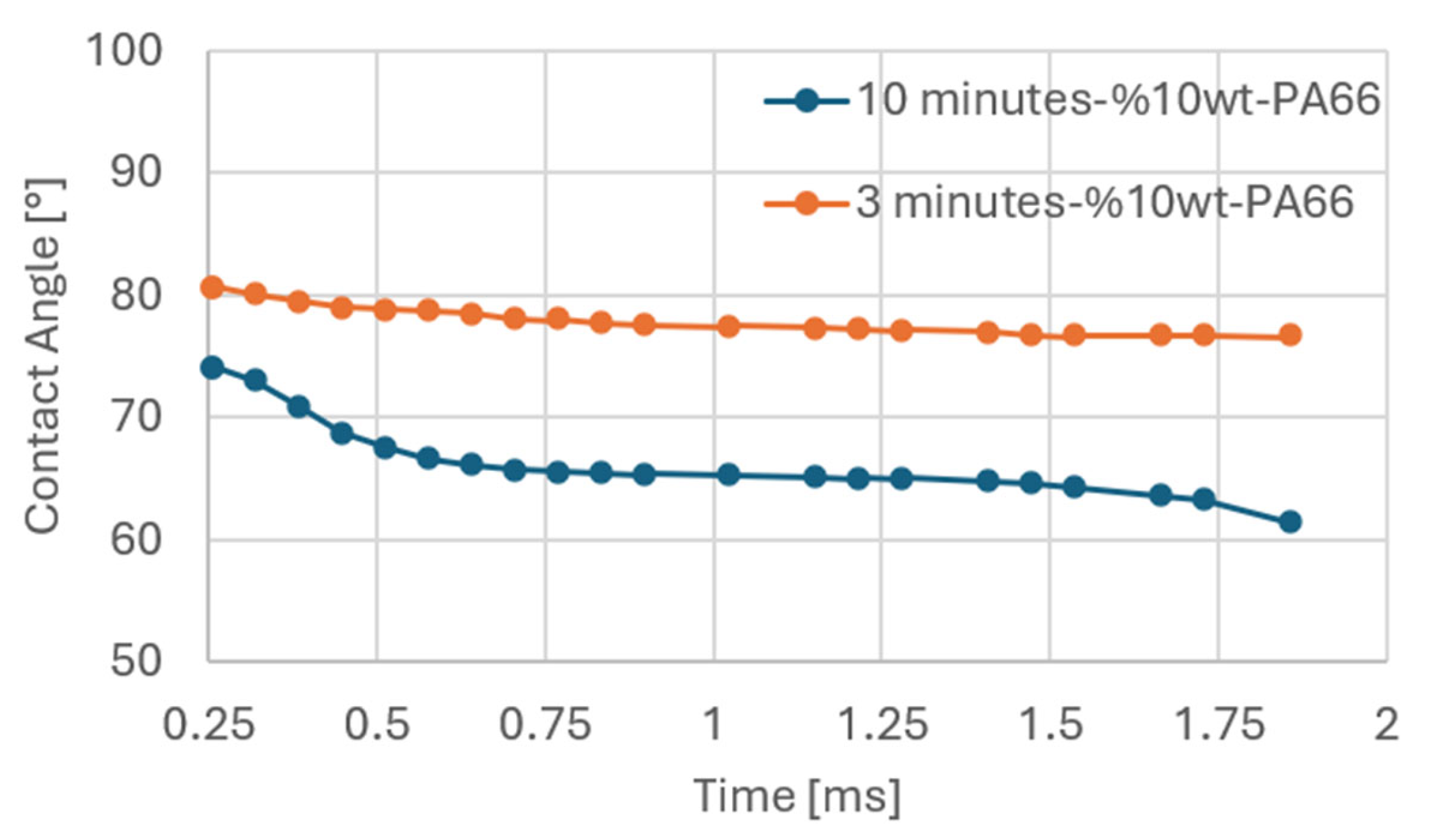
The following conditions are expected to occur for good surface preparation, i.e., minimal or no fiber damage, low residual resin, and a lower contact angle for bonded surfaces. For the electrospinning approach, it has been concluded that [30] 10-min coating time and %10 PA-66 concentration parameters are the optimized parameters for the used composite systems (M91/34%/UD194/IM7-12K) with the same bonding orientation. This combination gives the best wettability to the surface, which is quite crucial for bonding. Also, it is impossible to obtain residual resin because there is no ablation or peeling operation on the surface. Accordingly, contact angle analysis is considered an appropriate method for evaluating the wettability of bonded surfaces. Contact angle values as a function of different coating times are shown in Figure 12. Based on these values, a 10-min coating gives lower contact angles as compared to those for a 3-min coating. This means wettability for the 10-min coating is better and more suitable in terms of surface preparation.
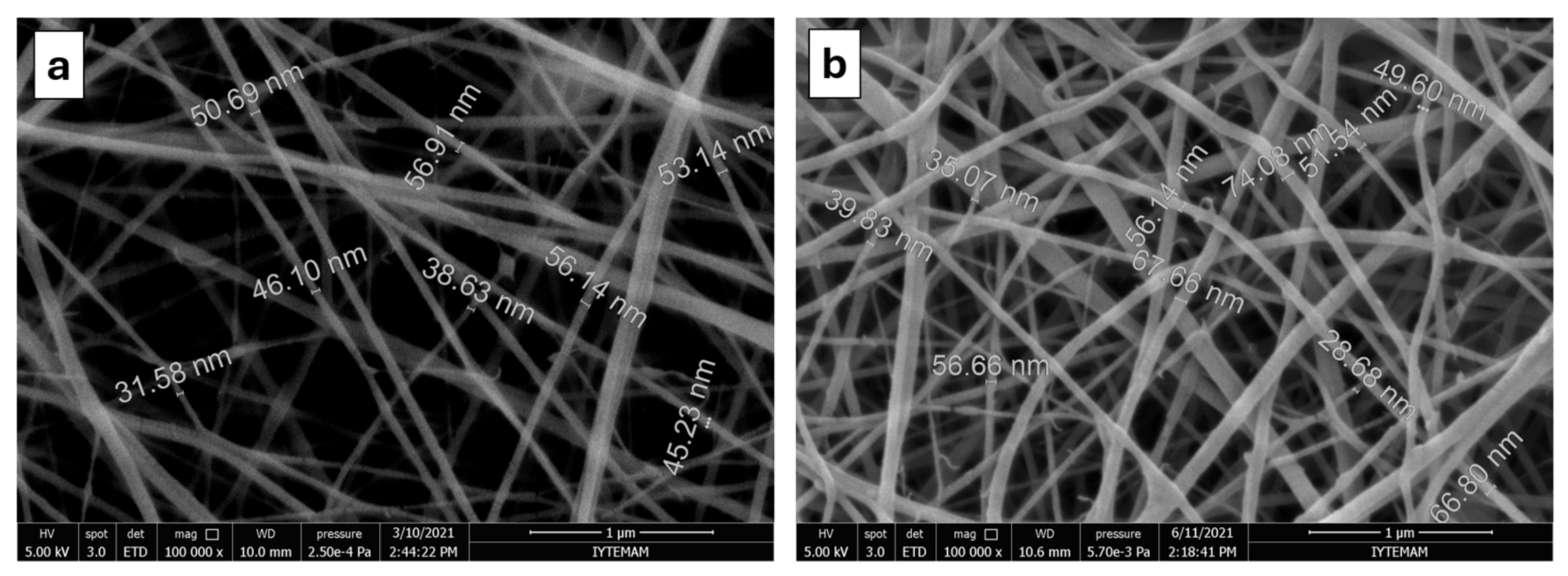
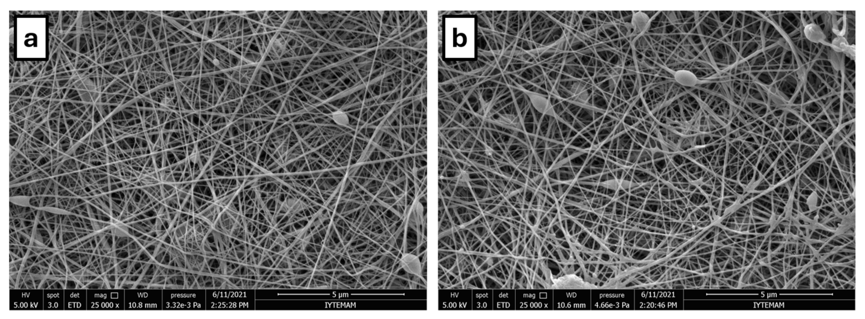
The amount of nanofibers increases with increasing coating time, as shown in Figure 13. The effect of coating time on areal weight density is 0.525 and 1.782 gsm for 3 and 10 min, respectively. The total weight increase of the prepregs due to nanofiber coating is lower than 1%. For the thickness effect of the coated polymer, it is 0.006 mm for 3 min coating and 0.020 mm for 10 min coating, respectively [30]. It has been assumed that thickness increase has no or negligible effect on test results.
Scanning electron microscopy (SEM) examination and a single lap shear test were performed to determine which solution concentrations are better in reference to bonding strength. Inhomogeneity and the number of beads increase with an increase of the PA-66 concentration of the solution, as shown in Figure 14. The inhomogeneities and formation of beads along fiber sections are not desired since these defects negatively affect the bonding performance. So, it was found that the %10 PA-66 concentration is suitable for coating nanofibers. Also, single-lap shear test results supported that a %10 PA-66 concentration gives the best structural performance.

2.5. Mechanical Testing

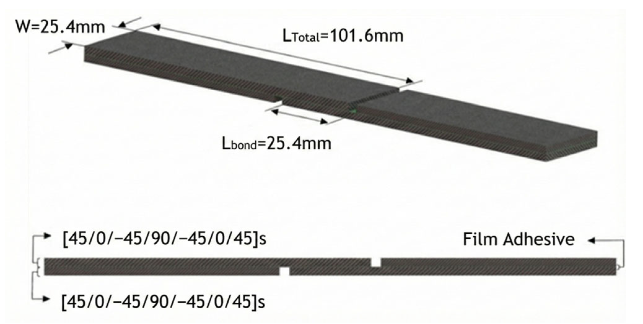
Single lap shear tests were performed in accordance with ASTM D5868 for each surface preparation technique. The dimensions and stacking sequence of the test specimen are given in Figure 15.
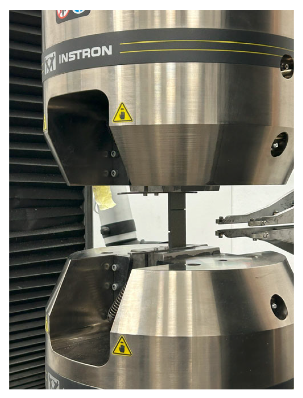
The Instron 5985 servo-hydraulic test setup used to perform single-lap shear tests within this study is shown in Figure 16.

3. Results

The mechanical performance of the carbon fiber reinforced polymer (CFRP) composites treated with three different surface preparation methods, i.e., peel-ply, laser ablation, and electrospinning, was evaluated within the study. The effectiveness of each method was assessed through single lap shear tests conducted in accordance with ASTM D5868. The aim is to compare the bonding strength achieved by each surface treatment and to identify the most effective technique in terms of enhancing adhesive joint performance for secondary bonded aerospace-grade composite structures.
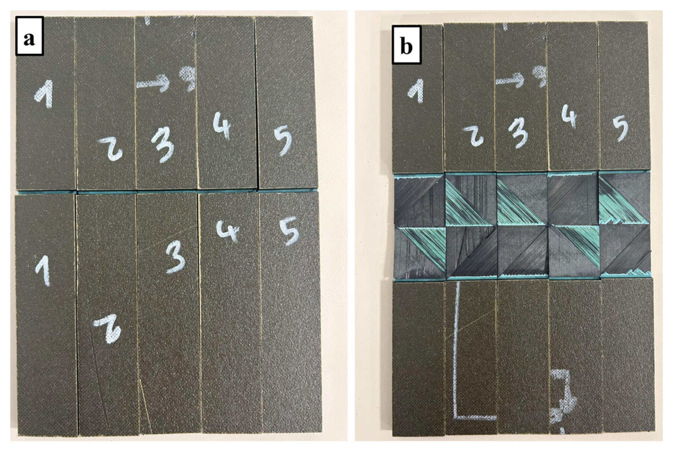
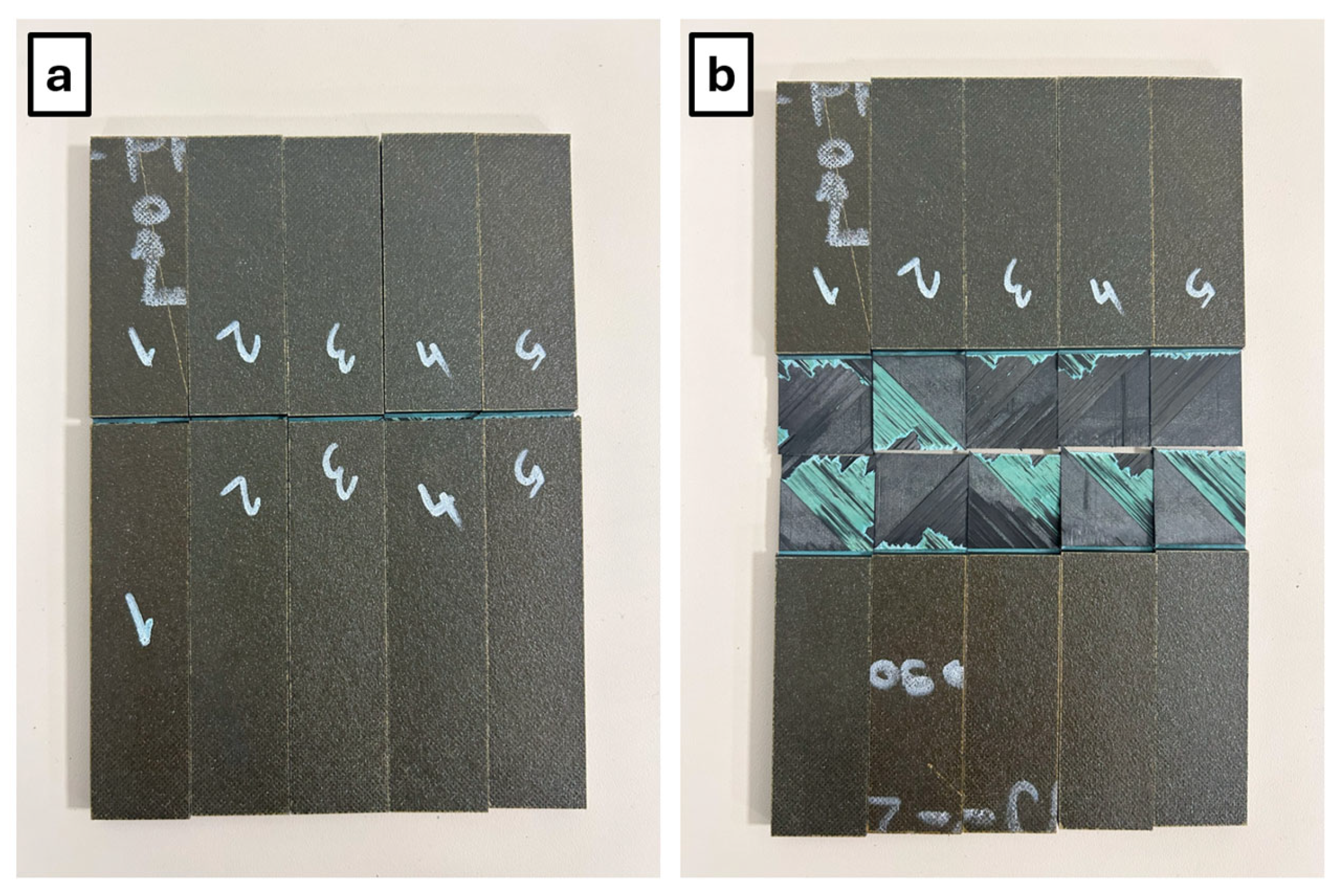
The single lap shear test results for specimens treated by the peel-ply method are shown in Figure 17 and Table 1. Based on the results, the failure mode of specimens was observed as both fiber tear and adhesive. The average shear strength of the specimens treated by peel-ply was measured as 15.18 MPa, as listed in Table 1.
A single lap shear test was performed on specimens treated by the laser ablation technique with the previously established optimum (30 W laser power and 10 m/s scanning speed) parameters [29]. The single lap shear test results are shown in Figure 18 and Table 1. Based on the results, the failure mode of the specimens was observed as both fiber tear and adhesive. The average shear strength of the specimens treated by laser ablation was measured as 20.68 MPa, as listed in Table 1.
A single lap shear test was performed on specimens treated by the electrospinning method. Two different concentrations of solutions (%10 and 14%) have been investigated in this study. Single lap shear test results are shown in Table 1 and Figure 19. Based on the results, the failure mode of the specimens was observed as both fiber tear and adhesive. The average shear strength of the specimens treated by electrospinning was measured as 18.20 MPa for %10 PA-66 and 16.77 MPa for %14 PA-66, as listed in Table 1.

Summary of the Mechanical Performance with Significance Test

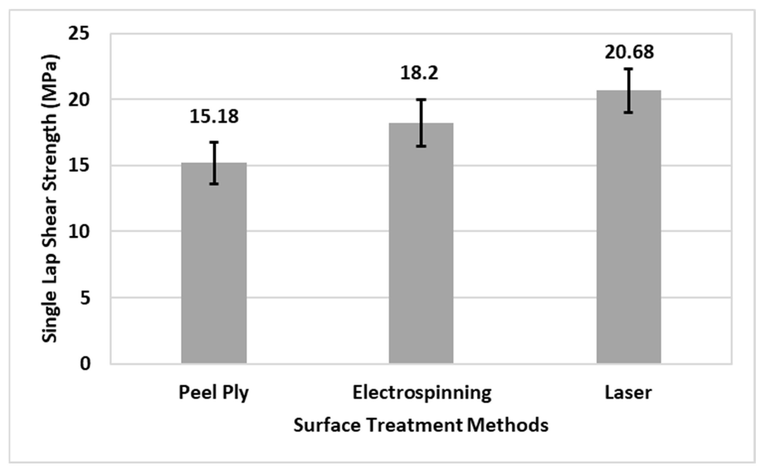
To evaluate the statistical significance of the different surface treatments, a one-way ANOVA was performed, followed by a Tukey HSD post hoc test according to Table 1. The analysis revealed a significant effect of the surface treatment method on the lap shear strength (F(2,12) = 11.53, p = 0.0008). Post hoc comparisons indicated that both laser ablation (20.68 ± 1.66 MPa, p < 0.001) and electrospinning (18.20 ± 1.76 MPa, p = 0.034) provided significantly higher bond strength compared to the peel-ply method (15.18 ± 1.60 MPa). While the laser treatment yielded the highest average strength, the difference between laser and electrospinning was not found to be statistically significant (p = 0.093).
Figure 20 shows the single lap shear strength values for comparison of three different surface treatment techniques that are investigated in this study.

4. Discussion

This study presents a comprehensive evaluation of three different surface treatment methods—peel-ply, laser ablation, and electrospinning—for the enhancement of adhesive bonding in carbon fiber reinforced polymer (CFRP) composites. Through systematic characterization of surface morphology, wettability, and mechanical performance, the investigation demonstrates the comparative advantages and limitations of each technique with the secondary bonding joining method.
The peel-ply method, although widely adopted in the aerospace industry for its simplicity and low cost, showed the lowest bond strength, with an average lap shear value of 15.18 MPa. Surface analysis revealed that the retained resin layer and potential contamination post-peel removal limit its bonding effectiveness, despite its moderate surface roughness profile.
Laser ablation, applied with previously established optimum parameters [29] (30 W power and 10 m/s scanning speed), yielded the highest performance with an average lap shear strength of 20.68 MPa. SEM analyses confirmed complete epoxy removal with minimal fiber damage under these conditions. Moreover, contact angle measurements showed a significant reduction, indicating enhanced surface wettability. The enhanced performance of laser-treated surfaces is likely linked to the direct exposure of carbon fibers and the qualitative improvement in surface wettability. Although specific surface free energy analysis was not performed to quantify the energetic changes, the reduction in contact angles suggests a more favorable interface for bonding. Furthermore, the removal of resin-rich potential weak boundary layers is proposed as a contributing mechanism based on the SEM morphological evidence. It should be noted, however, that since surface chemical characterization (such as XPS or FTIR) was not conducted, this mechanism remains inferred from the morphological observations rather than directly measured. Consequently, the relationship between the observed wettability and the resulting lap shear strength is treated as qualitative, and further studies are needed to provide a comprehensive energetic and chemical mapping of the interface.
Electrospinning, implemented using 10 wt% PA-66 solutions and a 10-min coating duration, resulted in a substantial improvement in bond strength (18.20 MPa). The nanofiber coatings provided a physically interlocked, high-energy surface without material removal, preserving laminate integrity while enhancing adhesion. Excess polymer concentration (14 wt%) was found to induce bead formation and inhomogeneities, degrading bonding efficiency. The electrospinning technique offers notable flexibility, being applicable to both cured and uncured surfaces, and introduces minimal additional weight (<1%).
All tested specimens exhibited a mixed failure mode, involving both adhesive and fiber-tear characteristics. This outcome indicates a generally strong interfacial bond, although the presence of localized adhesive failure suggests that further optimization of surface treatment parameters may enhance bond uniformity and strength. Fiber tear is the desired failure mode for joining; however, localized adhesive failure mode is attributed to improper surface cleaning after peeling for the peel-ply method, inhomogeneous energy density for the laser method, and inhomogeneous nanofiber accumulation on the surface for the electrospinning method, respectively.
It should also be noted that the single lap shear test conducted according to ASTM D5868 is inherently subject to secondary bending effects and load eccentricity. Although alignment tabs (pads) were utilized at the specimen ends to minimize initial eccentricity within the grips, the offset between the neutral axes of the two adherends still generates a local bending moment during load transfer. This phenomenon introduces significant peel stresses at the overlap ends, which contributes to the observed fiber-tear failure modes rather than pure adhesive shear failure. While these mechanics influence the absolute shear strength values, the comparative assessment of the surface treatment techniques remains valid, as all specimens featured identical geometry and material systems.
In summary, laser ablation proved to be the most effective technique in terms of interfacial bonding strength and surface conditioning, followed by electrospinning, while peel-ply remains the least effective among the three. However, both advanced techniques require precise control of process parameters to avoid surface damage or coating defects.
For future studies, researchers may focus on the homogeneity of laser application on the surface and homogeneous distribution of nanofibers on the surface for electrospinning to enhance the bonding performance.
The present investigation provides a benchmark for innovative surface treatments using a high-performance UD carbon/epoxy system with the same or similar resin content. However, it is important to note that surface chemistry and matrix thermal properties significantly influence ablation thresholds and nanofiber compatibility. Consequently, the results may vary for other composite systems, such as thermoplastic-based composites or glass-fiber-reinforced polymers, which remain a focus for future comparative studies.

Author Contributions

Conceptualization, M.E.I., M.T. and E.S.; methodology, M.E.I., M.T. and E.S.; validation, M.E.I. and S.D.; formal analysis, M.E.I., H.I. and G.E.; investigation, M.E.I., H.I. and G.E.; resources, M.T. and S.D.; data curation, M.E.I., H.I. and G.E.; writing—original draft preparation, M.E.I.; writing—review and editing, M.T., E.S. and S.D.; visualization, M.E.I.; supervision, M.T. and E.S.; project administration, M.T. and S.D.; funding acquisition, M.T. and S.D. All authors have read and agreed to the published version of the manuscript.

Funding

This research was funded by the Scientific and Technological Research Council of Türkiye (TUBITAK), grant number 218M701, and the APC was funded by the authors.

Data Availability Statement

The data presented in this study are available within the article.

Acknowledgments

This work was supported by the Scientific and Technological Research Council of Türkiye (TUBITAK) under Grant Number 218M701. The authors acknowledge Turkish Aerospace Industries Inc. (TUSAS) of Turkey for providing all materials and testing services and the IZTECH Center of Composite Materials for laser and electrospinning machines in this study.

Conflicts of Interest

The authors declare no conflict of interest. The funders had no role in the design of the study; in the collection, analyses, or interpretation of data; in the writing of the manuscript; or in the decision to publish the results.

Abbreviations

The following abbreviations are used in this manuscript:
ASTMAmerican Society for Testing and Materials
CFRPCarbon Fiber Reinforced Polymer
FTIRFourier Transform Infrared Spectroscopy
GSMGram per Square Meter
IRInfrared
IZTECHIzmir Institute of Technology
N/ANot Applied
PA-66Polyamide-66
SEMScanning Electron Microscopy
TUBITAKThe Scientific and Technological Research Council of Türkiye
TUSASTurkish Aerospace Industries
UDUnidirectional
XPSX-Ray Photoelectron Spectroscopy

References

  1. Sun, C.; Min, J.; Lin, J.; Wan, H.; Yang, S.; Wang, S. The effect of laser ablation treatment on the chemistry, morphology and bonding strength of CFRP joints. Int. J. Adhes. Adhes. 2018, 84, 325–334. [Google Scholar] [CrossRef] [Scilit]
  2. Li, X.; Ehrhardt, M.; Lorenz, P.; Han, B.; Lai, S.; Zimmer, K.; Xu, L.; Nan, P.; Ni, X. Influence of surface treatment with infrared nanosecond laser on adhesion performance of adhesion-bonded carbon fiber/epoxy composite. J. Adhes. Sci. Technol. 2019, 34, 1399–1425. [Google Scholar] [CrossRef] [Scilit]
  3. Fischer, F.; Kreling, S.; Jäschke, P.; Frauenhofer, M.; Kracht, D.; Dilger, K. Laser surface pre-treatment of CFRP for adhesive bonding in consideration of the absorption behaviour. J. Adhes. 2012, 88, 350–363. [Google Scholar] [CrossRef] [Scilit]
  4. Xie, Y.; Yang, B.; Lu, L.; Wan, Z.; Liu, X. Shear strength of bonded joints of carbon fiber reinforced plastic (CFRP) laminates enhanced by a two-step laser surface treatment. Compos. Struct. 2019, 232, 111559. [Google Scholar] [CrossRef] [Scilit]
  5. Li, S.; Sun, T.; Liu, C.; Yang, W.; Tang, Q. A study of laser surface treatment in bonded repair of composite aircraft structures. R. Soc. Open Sci. 2018, 5, 171272. [Google Scholar] [CrossRef] [Scilit]
  6. Nattapat, M.; Marimuthu, S.; Kamara, A.M.; Esfahani, M.R.N. Laser surface modification of carbon fiber reinforced composites. Mater. Manuf. Process. 2015, 30, 1450–1456. [Google Scholar] [CrossRef] [Scilit]
  7. Galantucci, L.M.; Gravina, A.; Chita, G.; Cinquepalmi, M. Surface treatment for adhesive-bonded joints by excimer laser. Compos. Part A Appl. Sci. Manuf. 1996, 27, 1041–1049. [Google Scholar] [CrossRef] [Scilit]
  8. Zhan, X.; Chen, S.; Li, Y.; Wang, H.; Yang, Y. Effect of surface cold ablation on shear strength of CFRP adhesively bonded joint after UV laser treatment. Int. J. Adhes. Adhes. 2019, 94, 13–23. [Google Scholar] [CrossRef] [Scilit]
  9. Oliveira, V.; Sharma, S.P.; de Moura, M.F.S.F.; Moreira, R.D.F.; Vilar, R. Surface treatment of CFRP composites using femtosecond laser radiation. Opt. Lasers Eng. 2017, 94, 37–43. [Google Scholar] [CrossRef] [Scilit]
  10. Rauh, B.; Kreling, S.; Kolb, M.; Geistbeck, M.; Boujenfa, S.; Suess, M.; Dilger, K. UV-laser cleaning and surface characterization of an aerospace carbon fibre reinforced polymer. Int. J. Adhes. Adhes. 2017, 82, 50–59. [Google Scholar] [CrossRef] [Scilit]
  11. Ledesma, R.I.; Palmieri, F.L.; Lin, Y.; Belcher, M.A.; Ferriel, D.R.; Thomas, S.K.; Connell, J.W. Picosecond laser surface treatment and analysis of thermoplastic composites for structural adhesive bonding. Compos. Part B Eng. 2020, 191, 107939. [Google Scholar] [CrossRef] [Scilit]
  12. Botana-Galvin, M.; Blanco, G.; Gonzalez-Rovira, L.; Rodriguez, M.A.; Botana, F.J. Adhesive behaviour of carbon fibre reinforced plastic panels manufactured using woven and unidirectional tape after ultraviolet laser surface treatment. J. Compos. Mater. 2017, 52, 1891–1903. [Google Scholar] [CrossRef] [Scilit]
  13. Leone, C.; Genna, S. Effects of surface laser treatment on direct co-bonding strength of CFRP laminates. Compos. Struct. 2018, 194, 240–251. [Google Scholar] [CrossRef] [Scilit]
  14. Reitz, V.; Meinhard, D.; Ruck, S.; Riegel, H.; Knoblauch, V. A comparison of IR- and UV-laser pretreatment to increase the bonding strength of adhesively joined Aluminum/CFRP components. Compos. Part A Appl. Sci. Manuf. 2017, 96, 18–27. [Google Scholar] [CrossRef] [Scilit]
  15. Li, Y.; Meng, S.; Gong, Q.; Huang, Y.; Gan, J.; Zhao, M.; Liu, B.; Liu, L.; Zou, G.; Zhuang, D. Experimental and theoretical investigation of laser pretreatment on strengthening the heterojunction between carbon fiber-reinforced plastic and aluminum alloy. ACS Appl. Mater. Interfaces 2019, 11, 22005–22014. [Google Scholar] [CrossRef] [Scilit] [PubMed]
  16. Bora, M.O.; Coban, O.; Akman, E.; Oztoprak, B.G.; Kutluk, T. Comparison of novel surface treatments of Al 2024 alloy for Al/CFRP adhesive bonded joints. Int. J. Adhes. Adhes. 2020, 103, 102721. [Google Scholar] [CrossRef] [Scilit]
  17. Gao, Q.; Li, Y.; Wang, H.; Liu, W.; Shen, H.; Zhan, X. Effect of scanning speed with UV laser cleaning on adhesive bonding tensile properties of CFRP. Appl. Compos. Mater. 2019, 26, 1087–1099. [Google Scholar] [CrossRef] [Scilit]
  18. Beylergil, B.; Tanoglu, M.; Aktas, E. Enhancement of interlaminar fracture toughness of carbon fiber–epoxy composites using polyamide-6, 6 electrospun nanofibers. J. Appl. Polym. Sci. 2017, 134, 45244. [Google Scholar] [CrossRef] [Scilit]
  19. Kim, C.; Park, S.H.; Lee, W.J.; Yang, K.S. Characteristics of supercapacitor electrodes of PBI-based carbon nanofiber web prepared by electrospinning. Electrochim. Acta 2004, 50, 877–881. [Google Scholar] [CrossRef] [Scilit]
  20. Lam, H.L. Electrospinning of Single Wall Carbon Nanotube Reinforced Aligned Fibrils and Yarns. Ph.D. Thesis, Drexel University, Philadelphia, PA, USA, 2004. [Google Scholar]
  21. Lyons, J.; Li, C.; Ko, F. Melt-electrospinning part I: Processing parameters and geometric properties. Polymer 2004, 45, 7597–7603. [Google Scholar] [CrossRef] [Scilit]
  22. Mohan, A. Formation and Characterization of Electrospun Nonwoven Webs. Ph.D. Thesis, Textile Management and Technology, North Carolina State University, Raleigh, NC, USA, 2002. [Google Scholar]
  23. Aljarrah, M.T.; Abdelal, N.R. Improvement of the mode I interlaminar fracture toughness of carbon fiber composite reinforced with electrospun nylon nanofiber. Compos. Part B Eng. 2019, 165, 379–385. [Google Scholar] [CrossRef] [Scilit]
  24. Beckermann, G.W.; Pickering, K.L. Mode I and Mode II interlaminar fracture toughness of composite laminates interleaved with electrospun nanofibre veils. Compos. Part A Appl. Sci. Manuf. 2015, 72, 11–21. [Google Scholar] [CrossRef] [Scilit]
  25. Kang, D.H.; Kang, H.W. Surface energy characteristics of zeolite embedded PVDF nanofiber films with electrospinning process. Appl. Surf. Sci. 2016, 387, 82–88. [Google Scholar] [CrossRef] [Scilit]
  26. Beigmoradi, R.; Samimi, A.; Mohebbi-Kalhori, D. Fabrication of polymeric nanofibrous mats with controllable structure and enhanced wetting behavior using one-step electrospinning. Polymer 2018, 143, 271–280. [Google Scholar] [CrossRef] [Scilit]
  27. Stachewicz, U.; Barber, A.H. Enhanced wetting behavior at electrospun polyamide nanofiber surfaces. Langmuir 2011, 27, 3024–3029. [Google Scholar] [CrossRef] [Scilit]
  28. Beylergil, B.; Tanoglu, M.; Aktas, E. Effect of polyamide-6,6 (PA 66) nonwoven veils on the mechanical performance of carbon fiber/epoxy composites. Compos. Struct. 2018, 194, 21–35. [Google Scholar] [CrossRef] [Scilit]
  29. Iplikci, H.; Barisik, M.; Turkdogan, C.; Martin, S.; Yeke, M.; Nuhoglu, K.; Esenoglu, G.; Tanoglu, M.; Aktas, E.; Dehneliler, S.; et al. Effects of nanosecond laser ablation parameters on surface modification of carbon fiber reinforced polymer composites. J. Compos. Mater. 2023, 57, 2825–2839. [Google Scholar] [CrossRef] [Scilit]
  30. Esenoglu, G.; Barisik, M.; Tanoglu, M.; Yeke, M.; Turkdogan, C.; Iplikci, H.; Martin, S.; Nuhoglu, K.; Aktas, E.; Dehneliler, S.; et al. Improving adhesive behavior of fiber reinforced composites by incorporating electrospun polyamide-6,6 nanofibers in joining region. J. Compos. Mater. 2022, 56, 4385–4400. [Google Scholar] [CrossRef] [Scilit]
Figure 1. The illustration of CFRP panel development by stacking the 14 layers of unidirectional carbon/epoxy prepregs.
Solids 07 00011 g001
Figure 2. Peel ply removal from cured CFRP part before bonding.
Solids 07 00011 g002
Figure 3. (a) Working principle of the laser system; (b) laser pulse pattern; (c) resin ablation mechanism.
Solids 07 00011 g003
Figure 4. (a) Preparation of PA-66 solution for electrospinning; (b) Working principle of electrospinning.
Solids 07 00011 g004
Figure 5. Illustration of (a) peel ply removal; (b) laser ablation; (c) thermoplastic nanofiber coating.
Solids 07 00011 g005
Figure 6. (a) Peel ply removal; (b) laser ablation; (c) nanofiber coating; (a1,b1,c1) before; (a1,b2,c2) after.
Solids 07 00011 g006
Figure 7. (a) Contact angle measurement device; (b) Droplet dispersion; (c) Stage of contact angle measurement with water droplet.
Solids 07 00011 g007
Figure 8. Illustration of thermal behaviors for different laser scanning speeds: (a) low laser scanning speed; (b) high laser scanning speed.
Solids 07 00011 g008
Figure 9. Contact angle measurement for different laser power and scanning speed.
Solids 07 00011 g009
Figure 10. SEM examination for (a) 20 W; (b) 25 W; (c) 30 W; (d) 35 W; (e) 40 W laser powers; (a1,b1,c1,d1,e1) 500× magnification; and (a2,b2,c2,d2,e2) 2500× magnification.
Solids 07 00011 g010
Figure 11. SEM examination for 30 W laser power: (a) 8 m/s; (b) 10 m/s; (c) 15 m/s.
Solids 07 00011 g011
Figure 12. Contact angle measurements for different coating times.
Solids 07 00011 g012
Figure 13. SEM examination for the (a) 3 min coating time (b) 10 min coating time.
Solids 07 00011 g013
Figure 14. Inhomogeneity and bead creation for (a) %10 PA-66 concentration; (b) %14 PA-66 concentration.
Solids 07 00011 g014
Figure 15. Dimensions of the single lap shear test specimen in accordance with the ASTM D5868 standard.
Solids 07 00011 g015
Figure 16. Test setup for the single lap shear test.
Solids 07 00011 g016
Figure 17. Single lap shear specimens for the peel-ply method (a) before testing; (b) after testing.
Solids 07 00011 g017
Figure 18. Single lap shear specimens for the laser method (a) before testing; (b) after testing.
Solids 07 00011 g018
Figure 19. Single lap shear specimens for the electrospinning method (%10 PA-66) (a) before testing; (b) after testing; (%14 PA-66); (c) before testing; (d) after testing.
Solids 07 00011 g019
Figure 20. Comparison of single lap shear strength for different surface treatment methods.
Solids 07 00011 g020
Table 1. Summary of the single lap shear test results with the significance test.
Surface TreatmentAverage Max Load (kN)Mean Shear Strength (MPa)Significance Group *
Laser Ablation13.35 ± 1.0620.68 ± 1.66a
Electrospinning (%10 PA-66)11.77 ± 1.1418.20 ± 1.76ab
Peel-Ply9.80 ± 1.0315.18 ± 1.60b
Electrospinning (%14 PA-66)10.83 ± 1.1616.77 ± 1.80N/A
* Means not sharing a common letter are significantly different (p < 0.05).
Disclaimer/Publisher’s Note: The statements, opinions and data contained in all publications are solely those of the individual author(s) and contributor(s) and not of MDPI and/or the editor(s). MDPI and/or the editor(s) disclaim responsibility for any injury to people or property resulting from any ideas, methods, instructions or products referred to in the content.