


Abstract
The mining industry faces escalating challenges in safely managing mine waste, particularly tailings storage facilities (TSFs), which are subject to a persistent risk of failure. The failure of these structures can have devastating consequences for both human safety and the environment. With the increasing number of active mines and TSFs, coupled with the effects of climate change, this situation is likely to worsen. To avoid the construction of conventional TSFs, the total co-disposal of tailings and waste rock within an integrated structure is particularly promising. Waste rock is well known for its favorable mechanical and hydraulic properties, which can help accelerate the drainage and consolidation of tailings while improving their mechanical behavior. The consolidated tailings, combined with the strong waste rock, can significantly enhance the stability of the integrated structure. If properly designed, this structure can ensure that tailings and waste rock mix upon failure, thereby preventing catastrophic mudflows. To achieve such a design, a thorough understanding and quantification of the flow behavior of tailings and waste rock are required. However, studies on this aspect are currently lacking in the literature. To fill this gap, three sets of laboratory tests were conducted to evaluate the flow behavior of tailings slurry in contact with waste rock. The tested tailings and waste rock were provided by a hard-rock gold mine. The first set of tests was performed using a small flume to evaluate the influence of the tailings–waste rock mixtures on the runout distance. The second was conducted in a large flume to evaluate the flow of tailings confined within a waste rock cell with lateral restrictions, while the third set investigated tailings confined within a waste rock cell without these restrictions. The results showed that the presence of waste rock contributes to mitigating the flow of tailings. In particular, the runout distance decreases with an increasing waste rock-to-tailings ratio, higher pulp density, and longer settling times. In contrast, this distance increases with larger waste rock cell diameters and higher elevations. Nevertheless, the runout distance can be entirely controlled or reduced to zero by limiting the size of the waste rock cell, increasing the tailings pulp density, or prolonging the settling time. The results also indicate that conventional filter or retention criteria need to be improved by considering pulp density, hydraulic gradient, and other influencing factors when evaluating the migration of tailings slurry through waste rock.
1. Introduction
Mining operations generate large quantities of non-economic materials, primarily waste rock and tailings. The safe and sustainable management of these mine wastes remains one of the most critical challenges facing the mining industry. Traditionally, waste rock and tailings have been managed separately, with waste rock stored in waste rock piles and tailings deposited in tailings storage facilities (TSFs) [1,2]. Despite decades of research and engineering advances, these facilities, particularly TSFs, continue to present significant geotechnical and environmental challenges. A TSF failure can result in the rapid and uncontrolled release of large volumes of tailings capable of traveling considerable distances [3,4,5], potentially causing severe impacts on the environment, infrastructure, economic activities, and human lives [6]. A prominent example is the failure of Dam I at the Córrego do Feijão mine near Brumadinho, Brazil, on 25 January 2019. Approximately 12 million m3 of tailings were released, resulting in 270 fatalities alongside extensive environmental and infrastructural damage [7,8].
To mitigate the risks associated with conventional slurry tailings deposition, filtered tailings, commonly referred to as “dry stack” tailings, have increasingly been considered and adopted. This approach is particularly favored where water recovery, reduced water storage, or site-specific environmental constraints are critical. By removing a substantial portion of the process water prior to deposition, filtering reduces the volume of free water stored within the facility and thereby limits both the mobility and the consequences of a potential failure compared to conventional slurry-based facilities. However, “dry-stack” tailings are not entirely dry, and their degree of saturation can fluctuate over time depending on the regional climate, including rainfall and snowfall. Consequently, their performance depends heavily on material properties, moisture content, compaction, drainage conditions, stack geometry, construction quality, and climatic conditions. In regions characterized by high precipitation or a positive water balance, infiltration and subsequent changes in water content can adversely affect the mechanical behavior and stability of the stack.
Recent events demonstrate that dry stacking is not inherently immune to geotechnical instability. On 18 February 2026, a major landslide occurred at a tailings disposal area operated by PT QMB New Energy Materials in the Indonesia Morowali Industrial Park (IMIP), Central Sulawesi, resulting in the death of an excavator operator and the rapid displacement of tailings material that engulfed several pieces of heavy equipment [9]. Based on an examination of video footage, a hydrogeologist and mine waste expert identified the failure mechanism as consistent with the liquefaction of a filtered-tailings stack [9]. This incident underscores the fact that dewatering alone does not eliminate the potential for rapid post-failure tailings mobility and that the geotechnical behavior of filtered-tailings stacks remains critically dependent on factors such as water content, drainage, material properties, stack geometry, foundation conditions, and construction practices [10].
These recent incidents, coupled with the persistent failure of conventional TSFs, emphasize the urgent need to investigate alternative and potentially more resilient approaches to mine waste management. One such approach is integrated mine-waste management, where tailings and waste rock are managed within a single, unified disposal system rather than in completely separate facilities [2,11,12]. While various configurations have been proposed, the associated terminology remains inconsistent across the literature. Following the framework adopted by Habte and Bocking [13], three broad configurations can be distinguished based on the degree of interaction or mixing between the two waste streams: co-mingling, co-placement, and co-deposition.
Co-mingling involves actively mixing tailings and waste rock to produce a relatively homogeneous composite material. Mechanical equipment may be required to facilitate the mixing process and to promote the filling of voids within the coarse waste rock by the finer tailings [13,14]. Although this approach can provide a relatively uniform and controlled material, it may require additional handling, processing, and energy, which can increase operational complexity and cost.
Co-deposition involves transporting tailings and waste rock separately but depositing them in a manner that allows some degree of mixing to occur during or as a result of deposition. The resulting degree of mixing is therefore dependent on the deposition method, material properties, and operating conditions and may be less controlled than in co-mingling [13,14].
Co-placement involves transporting the two waste streams separately and placing them within the same disposal area while maintaining a relatively low degree of intentional mixing. Examples include the incorporation of waste rock within a tailings facility, the construction of waste rock inclusions or internal structures, and the placement of tailings and waste rock within an open pit [15,16,17,18]. The regulatory acceptability of such configurations depends on the characteristics of the waste materials and the applicable regulatory requirements. In Québec, for example, Directive 019 provides requirements for the management and disposal of mine waste, including waste rock and tailings, but does not categorically prohibit their co-disposal. The acceptability of a specific configuration depends on factors including the geochemical characteristics of the materials and the design and environmental performance of the disposal facility [19].
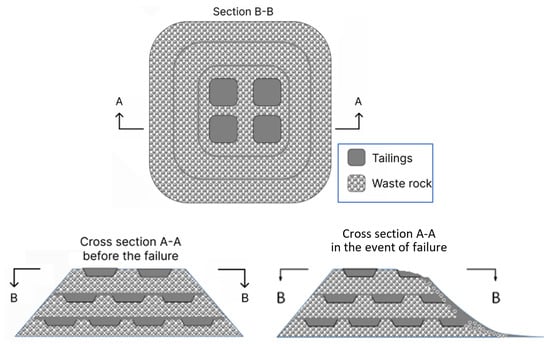
Figure 1 presents the concept of the total co-disposal of chemically non-reactive tailings and waste rock in an integrated structure, referred to here as CtRS [20]. Despite the similarity of Figure 1 to the layered or “sandwich” co-disposal concept described by Leduc and Smith [14] and its strong resemblance to Figure 15.6 in Hawley and Cunning [21], this concept was entirely inspired by the conference and seminar presentations of Aubertin and co-workers on the waste rock inclusion approach [2,16,22]. In this configuration, waste rock layers or cells are incorporated within the tailings deposit. The high permeability of the waste rock may facilitate the drainage of excess pore water from the tailings, thereby accelerating consolidation in both the vertical and horizontal directions. In addition, the relatively high shear strength and stiffness of the waste rock may contribute to the overall mechanical performance and geotechnical stability of the integrated structure [20]. As successive layers of waste rock and tailings are placed, the surcharge imposed by the overlying materials may promote further consolidation of the previously deposited tailings, potentially increasing their density and shear strength while reducing their volume. These processes may improve the overall stability of the disposal system and reduce its environmental footprint. However, their effectiveness depends on the hydraulic and mechanical properties of the constituent materials, as well as the geometry and construction sequence of the structure.
Figure 1.
Concept of total co-disposal of non-reactive tailings and waste rock in an integrated structure, CtRS [20].
An additional potential advantage of the proposed configuration is its behavior in the event of a structural failure. If the CtRS structure is appropriately designed and constructed, the mechanical interaction between the waste rock and tailings may provide additional resistance to tailings mobility, potentially reducing the runout distance and limiting the extent of the tailings spread. This interaction could consequently mitigate the consequences of a failure and reduce the likelihood of the released tailings developing into a catastrophic flow. Nevertheless, such behavior cannot be assumed a priori. In particular, the post-failure interaction between the waste rock and tailings, specifically the possibility of tailings migrating through the voids of the waste rock, must be evaluated experimentally and analytically before this configuration can be considered a reliable means of reducing failure consequences.
Despite the potential advantages of total co-disposal, the design of an integrated tailings–waste rock structure requires a fundamental understanding of its behavior under both normal operating conditions and potential failure scenarios. In particular, the post-failure flow and runout behavior of tailings interacting with waste rock remain insufficiently understood. While several studies have focused on estimating the runout distances of conventional tailings [23,24,25,26,27,28,29,30], filtered tailings [31], and waste rock piles [32,33], no published study currently addresses the runout distance of integrated tailings and waste rock structures. The ability of waste rock to restrict tailings mobility, the mechanisms governing tailings migration through waste rock voids, and the parameters controlling the resulting runout distance all require further investigation.
To address this knowledge gap and understand the key factors influencing the runout distance of co-disposal structures, a series of laboratory flow tests was conducted using three configurations: (i) tailings alone, (ii) a homogeneous mixture of tailings and waste rock, and (iii) tailings confined within a waste rock cell. These configurations were designed to investigate the role of waste rock in restricting tailings mobility and reducing runout distance. The effects of the waste rock cell diameter (equivalent to the volume of tailings slurry), the base thickness of the waste rock, the pulp density of the tailings slurry, the settling time of the tailings, and the waste rock-to-tailings ratio on the resulting runout behavior were evaluated experimentally. Although laboratory-scale investigations cannot fully reproduce the complexity of field-scale co-disposal structures, they provide a valuable first step toward identifying the governing mechanisms controlling post-failure behavior. The objective of the present study is therefore not to predict the response of full-scale facilities, but rather to investigate the effects of key variables on runout behavior under controlled experimental conditions. Ultimately, these results provide insight into the mechanisms governing tailings–waste rock interaction during flow and contribute to the development of design criteria for integrated mine-waste disposal structures.
2. Laboratory Tests
2.1. Materials
The tailings used in this study were obtained from a mine located in northern Quebec (Canada). These tailings are chemically non-reactive, and the mine does not experience issues with acid mine drainage or neutral contaminated drainage. The waste rock consisted of a multi-source mixture that had been stored in the laboratory for several years. It is similarly considered chemically non-reactive, as it showed no signs of chemical reaction or color change.
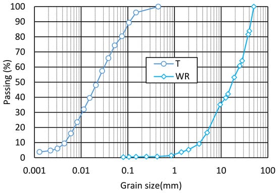
Figure 2 presents the particle size distribution (PSD) of the tailings (T) in accordance with ASTM D7928-21e1 [34] and the waste rock (WR) in accordance with ASTM D6913/D6913M-17 [35]. The characteristic particle diameters of the tailings are D10 = 0.0045 mm, D30 = 0.01 mm, and D60 = 0.031 mm (where Dn represents the particle diameter at n% passing), resulting in a coefficient of uniformity (Cu) of 6.8. For the WR, the particle size ranged from 0.08 to 50 mm, and the characteristic particle diameters D10, D30, and D60 are 3.5, 8, and 25 mm, respectively, yielding a coefficient of uniformity of 7.1. The specific gravity of the tailings was 2.73, determined in accordance with ASTM D854-021 [36]. The specific gravity of the waste rock was not determined due to the heterogeneous nature of the multi-source mixture.
Figure 2.
Particle size distributions (PSD) of the tested tailings (T) and waste rock (WR).
2.2. Experimental Setup
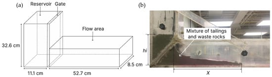
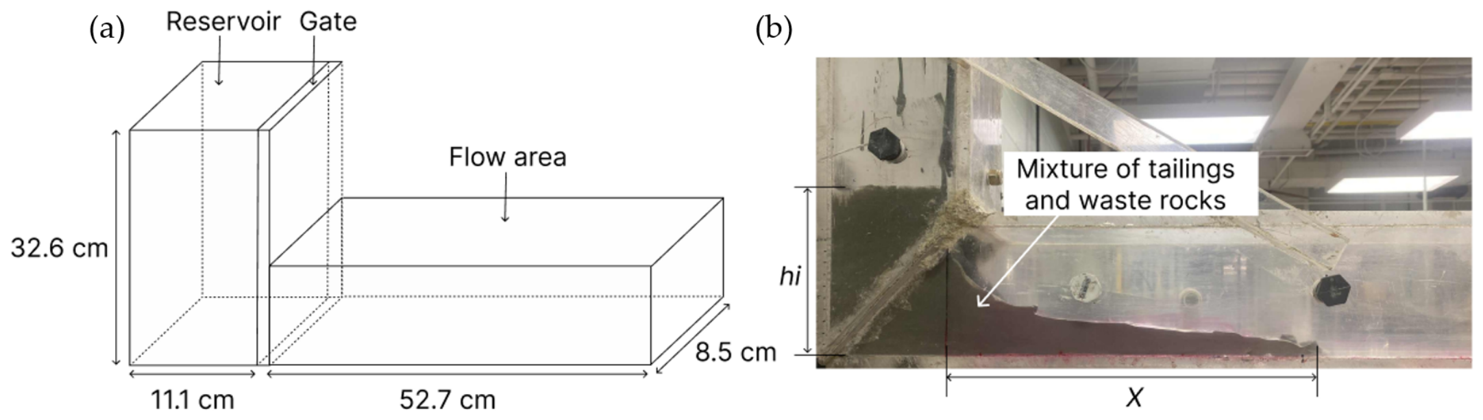
In this study, preliminary flow tests were conducted using a small flume available at the beginning of the project. Figure 3a shows a schematic representation of this flume, which is equipped with a gate to trigger the flow. The flume reservoir measures 11.1 cm × 8.5 cm × 32.6 cm, and the channel is 52.7 cm long. Figure 3b presents a photograph of the Plexiglas flume. The variable hi designates the initial height of the material inside the reservoir, and X represents the runout distance measured from the gate to the flow front.
Figure 3.
The small flume: (a) schematic representation; (b) photograph.
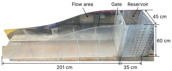
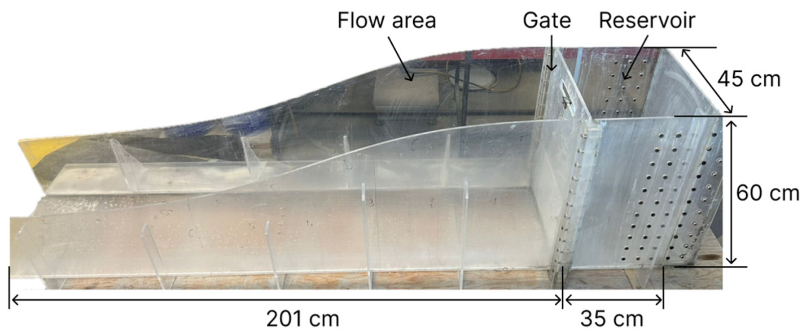
Subsequently, a large-scale Plexiglas flume was constructed. Figure 4 illustrates a photograph of the large flume, which consists of a reservoir (35 cm long, 45 cm wide, and 60 cm high), a gate, and a 201 cm-long channel. The length and the width of the reservoir are adjustable.
Figure 4.
Photograph of the large Plexiglas flume.
2.3. Flow Testing Program
In this study, three sets of flow tests were conducted. The first set was performed using the small flume to evaluate the influence of the tailings–waste rock mixtures on the runout distance. The second set was conducted in the large flume to evaluate the flow of tailings confined within a waste rock cell with lateral restrictions, while the third set investigated tailings confined within a waste rock cell without any lateral restrictions.
2.3.1. Flow Tests on Tailings and Waste Rock Mixtures
In this series, the flow behavior of pure tailings slurry and homogeneous tailings–waste rock mixtures was evaluated using the small flume. The tailings were first thoroughly mixed at five different pulp densities (P, also referred to as the solid percentage, defined as the ratio of dry tailings mass to total slurry mass): 65%, 67%, 69%, 71%, and 73%. The waste rock was sieved to prepare three distinct particle size fractions: 3.36–5 mm, 5–8 mm, and 8–12.5 mm, respectively. The waste rock-to-tailings mass ratio (RWT/T), defined as the ratio of waste rock mass to tailings slurry mass, ranged from 0 to 0.8. This ratio was varied by increasing the mass of waste rock while keeping the mass of the tailings slurry constant. The required mass of waste rock (MWR) was determined using a simple calculation as follows:
where MT is the mass of the tailings slurry, and a dry-solids-based waste rock-to-tailings (WR/T) ratio, DRWR/T, can subsequently be calculated as follows:
A tailings sample was taken to validate the pulp density immediately prior to testing. The initial height (hi) of the material inside the reservoir was then measured (Figure 3b). Following failure triggered by lifting the gate, the final runout distance (X) was recorded. Table 1 presents the testing program conducted with the small flume to evaluate the influence of the WR/T ratio (RWR/T). The corresponding DRWR/T values are listed in Table 2.
Table 1.
Testing program conducted in the small flume to evaluate the influence of the WR/T ratio.
Table 2.
Dry-solids-based WR/T ratio, DRWR/T.
2.3.2. Flow Tests on Tailings Confined Within a Waste Rock Cell
In this series, the large flume was used to evaluate the post-failure flow behavior of tailings confined within a waste rock cell with lateral restriction. In this setup, the waste rock was assumed to act as an obstacle and to provide surface roughness to dissipate the kinetic energy of the tailings during flow.
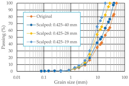
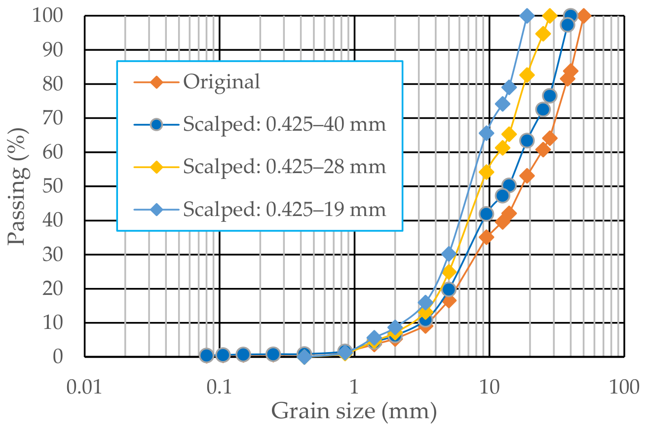
Unlike the waste rock preparation described in Section 2.3.1, the waste rock samples for each test were prepared by applying the double scalping technique [37,38,39,40,41,42,43], with maximum particle sizes (dmax) of 40, 28 and 19 mm, respectively. The minimum particle size (dmin) of the waste rock samples was kept at 0.425 mm. The PSD curves of the scalped waste rock samples, along with the original waste rock curve, are shown in Figure 5. Applying the scalping technique consequently increased the percentage of fine particles in the scalped samples.
Figure 5.
PSD curves of the double-scalped waste rock samples with dmax of 40, 28, and 19 mm and dmin = 0.425 mm, compared to the original waste rock PSD.
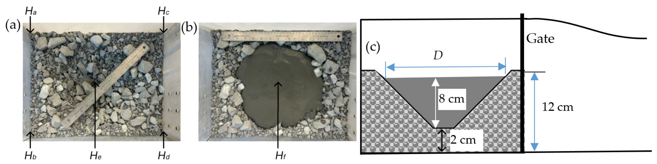
The waste rock was homogenized and placed into the flume reservoir to form a cell with a diameter (D) of approximately 30 or 38 cm. The initial height of the waste rock was measured using a laser sensor at five points (labeled a, b, c, d, and e), as shown in Figure 6a. The average value of the measured heights Ha, Hb, Hc, and Hd was approximately 12 cm, while He was approximately 2 cm. Tailings with a pulp density (P) of approximately 66% were mixed to ensure homogeneity and then poured into the cell. The thickness of the tailings slurry was approximately 8 cm, determined by subtracting He from the total height (Hf) measured with the same laser instrument (Figure 6b). A schematic representation of the longitudinal cross-section is presented in Figure 6c. The gate was abruptly removed to trigger the tailings flow. The runout distance traveled by both types of mine waste was measured, and the flow pattern was photographed.
Figure 6.
A waste rock cell: (a) before pouring the tailings; (b) after pouring the tailings; and (c) schematic representation of the longitudinal cross-section.
2.3.3. Tailings Confined Within a Waste Rock Cell Without Lateral Restrictions
While flume tests provide valuable insights into tailings flow behavior with or without waste rock, the lateral restriction imposed by the channel walls does not correspond to field conditions involving a wide plateau. In addition, the volume of tested material is limited by the reservoir dimensions. This third series of flow tests on an unconfined platform is therefore necessary to understand and evaluate tailings flow behavior in the absence of lateral boundary effects.
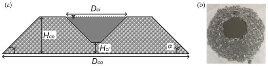
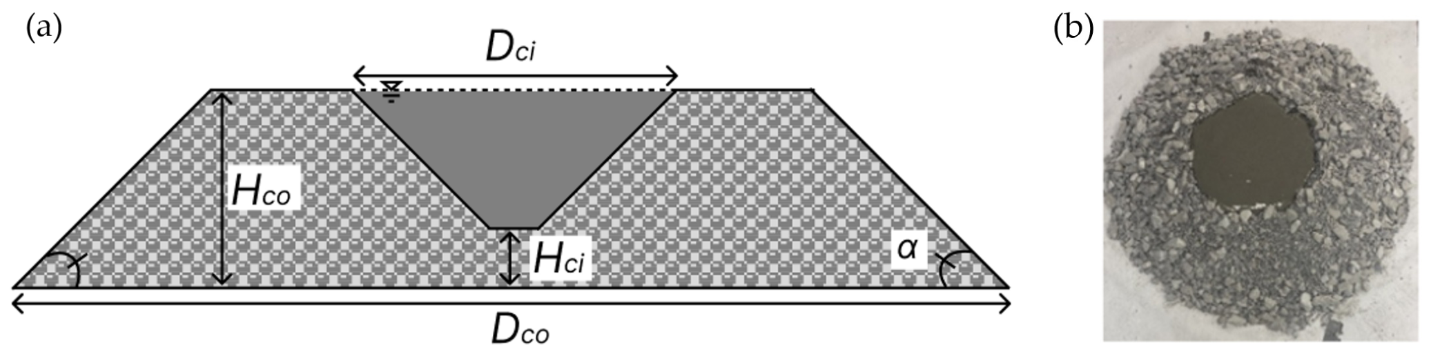
Figure 7 shows a schematic representation (Figure 7a) and a photograph (Figure 7b) of a single waste rock cell constructed in the laboratory using the co-disposal technique (CtRS). In Figure 7a, Dci and Dco represent the top and base diameters of the cell, respectively; Hci and Hco are the inside and outside heights of the waste rock cell, respectively; and α is the slope angle (equal to the angle of repose of the waste rock).
Figure 7.
(a) Schematic representation of a single waste rock cell containing tailings before failure, and (b) photograph of the experimental setup.
The double scalping technique was applied to obtain three scalped waste rock samples [37,38,39,40,41,42,43]. The resulting samples had maximum particle sizes (dmax) of 40, 28, and 19 mm, respectively, while the minimum particle size (dmin) was kept at 0.425 mm. The PSD curves of these scalped waste rock samples are presented in Figure 5.
The thoroughly mixed tailings slurry was poured into the waste rock cell, as shown in Figure 7b. The failure of the structure and the subsequent tailings flow were triggered by progressively or abruptly removing a section of the waste rock at a chosen location.
Table 3 presents the testing program designed to evaluate the influence of the cell internal diameter (Dci), the base layer thickness (Hci), the waste rock PSD, the pulp density (P), and the tailings settling time (ts) on the tailings runout distance. For the tests investigating various cell diameters, the required mass of waste rock was increased by 22% for the 45 cm cell and by 37% for the 55 cm cell, compared to the 30 cm reference cell. For the tests with various base-layer thicknesses, the waste rock mass in the base was increased while keeping the mass of the tailings slurry constant within the same cell volume. For the tests investigating the effect of waste rock dmax, the cell geometry and waste rock mass were kept constant, while the mass of the poured tailings was varied. This variation was necessary because coarser waste rock particles allowed more tailings to migrate through the interstitial voids; consequently, a larger mass of tailings was required to fully fill the cell.
Table 3.
Testing program for a single CtRS waste rock cell.
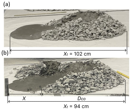
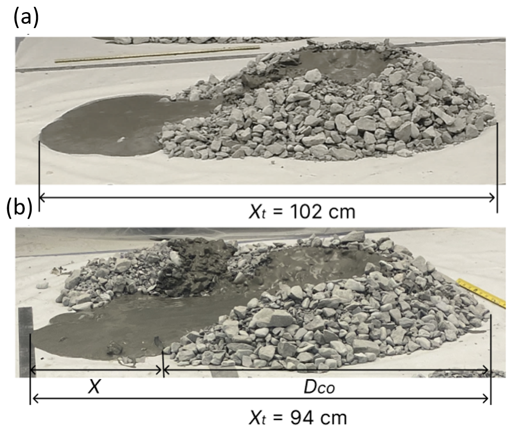
Two types of tests were conducted to induce failure and subsequent tailings flow: progressive removal (Case 1) and instantaneous removal (Cases 2, 3, and 4) of the waste rock particles at the front of the cell. Figure 8 shows photographs of the final flow state of the tailings following progressive failure (Figure 8a) and instantaneous failure (Figure 8b). These two tests were conducted under identical initial conditions, including the same waste rock particle size fraction (0.425–28 mm), the same tailings pulp density (≈67%), and the same initial cell geometry. The progressive failure was induced by manually removing the waste rock particles from the front of the cell using a spoon. This method resulted in a gradual and controlled release of the confined tailings, with minimal integration of waste rock particles into the flow (Figure 8a). In contrast, the instantaneous failure was triggered by the rapid removal of the frontal waste rock using a shovel in a single motion. This method produced a sudden, uncontrolled, and massive release of both tailings and waste rock (Figure 8b). Since this study focuses on simulating an uncontrolled, sudden failure event, the instantaneous failure mode was adopted for all remaining tests.
Figure 8.
Final flow states for different failure modes: (a) progressive failure, and (b) instantaneous failure.
Following each failure event, the total distance (Xt) between the flow front and the initial back edge of the structure was measured. The final runout distance (X) was then calculated by subtracting the outside cell diameter (Dco) from the total measured distance (Xt) as follows:
3. Results and Discussion
3.1. Flow Tests on Tailings and Waste Rock Mixtures
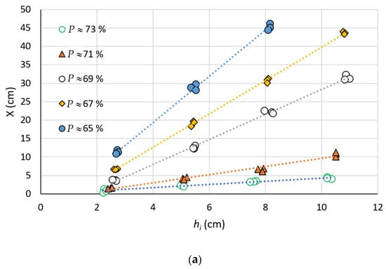
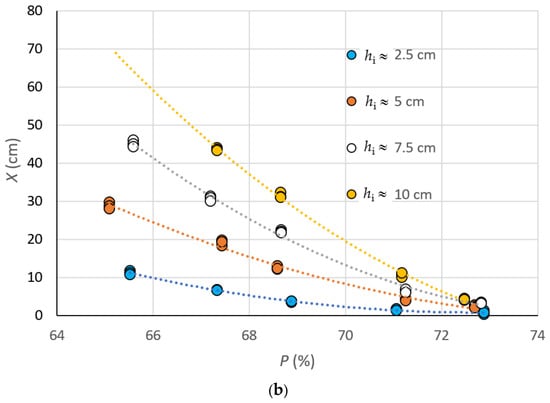
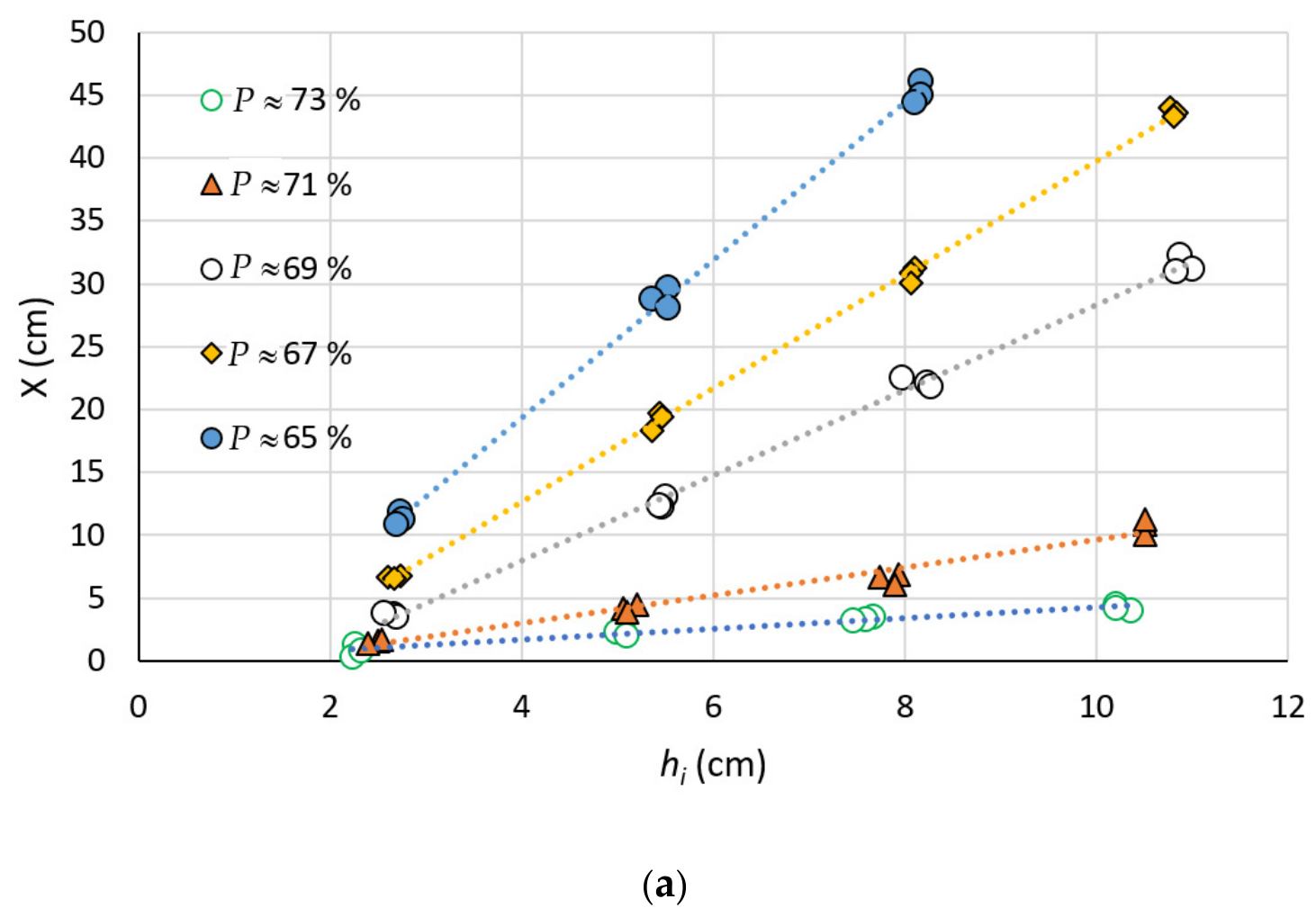
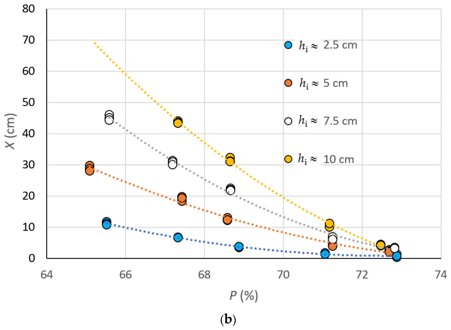
Figure 9 shows the variation in the runout distance of the pure tailings as a function of the initial height for different pulp densities (Figure 9a) and the variation as a function of the pulp density for different initial heights (Figure 9b). For a given pulp density, the runout distance increases linearly with the initial height of the tailings slurry. This upward trend is consistent with the expected physical behavior. With a greater initial height, the tailings slurry possesses a higher volume and greater potential energy, which are transformed into greater kinetic energy once the gate is lifted, resulting in a longer runout distance. However, the empirical solutions of Rico et al. [25] and Larrauri and Lall [27] predict a nonlinear relationship with increasing initial height. A plausible explanation for this discrepancy is that the range of initial heights evaluated in this study is insufficiently wide. More tests are thus necessary.
Figure 9.
Runout distance of pure tailings as a function of (a) initial height (hi) for different pulp densities (P) and (b) pulp density for different initial heights.
Conversely, for a given initial height, the runout distance decreases exponentially with increasing pulp density. This trend corresponds to that predicted by the model of Jeyapalan et al. [23,24]. With a higher pulp density, the tailings exhibit higher yield stress and viscosity [44,45,46,47,48,49], increasing flow resistance and resulting in a shorter runout distance.
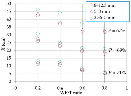
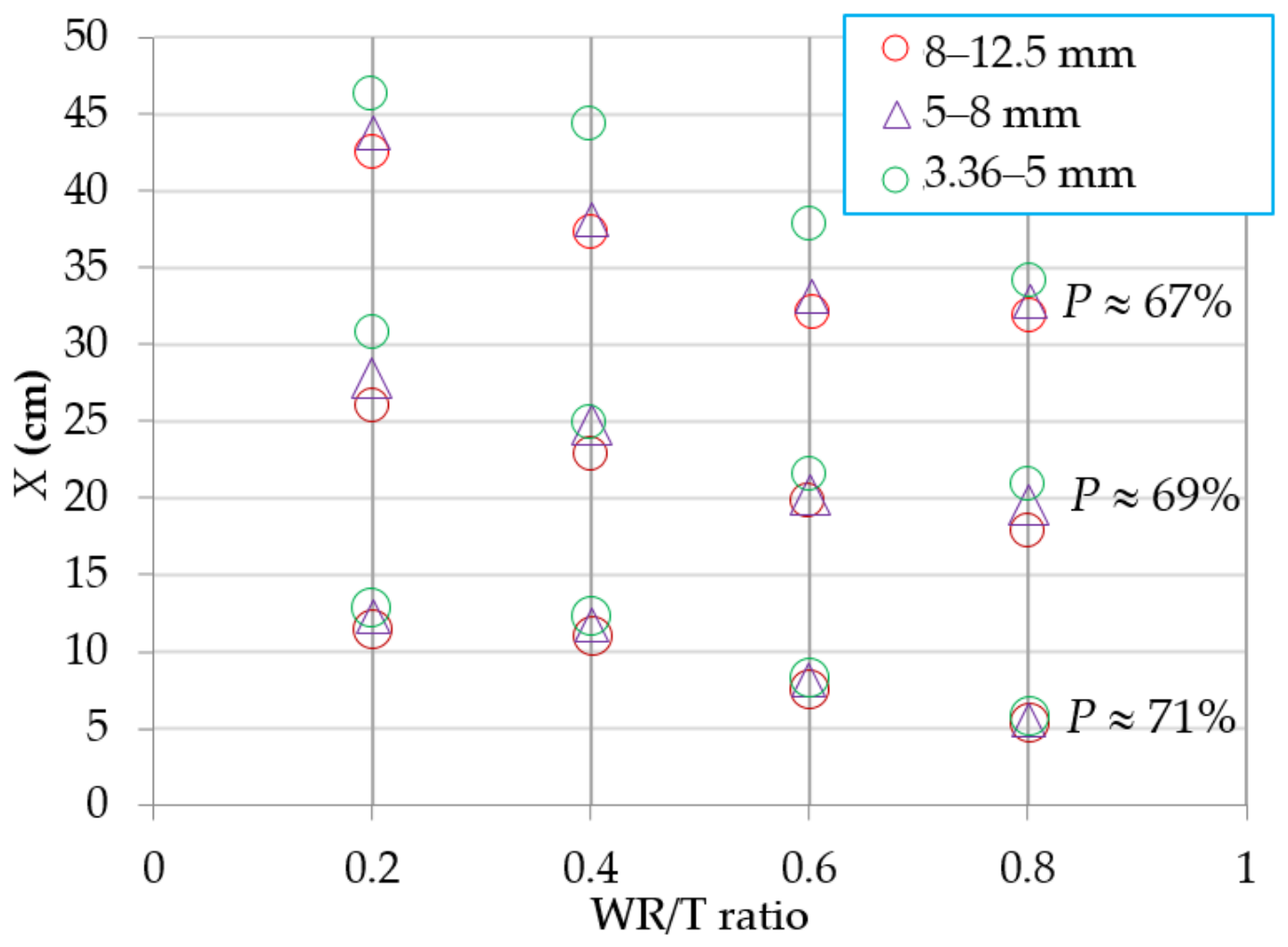
Figure 10 presents the variation in the runout distance as a function of the WR/T ratio for different pulp densities and waste rock particle sizes. For a given WR/T ratio, the runout distance decreases as the tailings pulp density increases, similar to the case of pure tailings shown in Figure 9.
Figure 10.
Runout distance as a function of the WR/T ratio for various waste rock particle sizes and tailings pulp densities.
For a given pulp density, the runout distance of the mixture decreases with an increasing WR/T ratio. This reduction occurs even though the total volume and initial height of the mixture increase with the WR/T ratio due to the addition of waste rock. These results indicate that incorporating waste rock particles into tailings effectively restricts tailings mobility. This trend is consistent with expectations. For a given pulp density, an increase in the WR/T ratio via the addition of waste rock indirectly increases the total solid content, which in turn enhances the mechanical and rheological properties of the mixture. This impedes flow, leading to a shorter runout distance. This behavior can be explained by the improved mechanical properties of tailings following the addition of waste rock, as reported by Wickland et al. [11], but contradicts the finding of Hane et al. [50]. The latter reported that the rheological properties of cemented paste tailings aggregate fill do not change with an increasing volume percentage of aggregates.
For a given pulp density and WR/T ratio, the runout distance slightly decreases with increasing waste rock particle size, although this trend is not very pronounced. These results are also consistent with expectations. When the waste rock particles in the mixture are larger, more potential and/or kinetic energy is required to trigger and sustain their movement. For a given configuration with a given potential energy, coarser waste rock particles consume more kinetic energy to initiate movement, thereby acting as obstacles to the tailings flow.
While the results for both the pure tailings slurry and the tailings–waste rock mixtures indicate that the runout distance largely depends on the pulp density, none of the existing theoretical, numerical, or empirical models directly accounts for this parameter. Rather, most theoretical and numerical models indirectly account for it through rheological properties [23,24,30,32,51], which in turn depend not only on the pulp density but also on the PSD and mineralogy [47,50,52,53,54]. Consequently, detailed chemical, mineralogical, and microstructural characterizations of tailings and waste rock through X-ray diffraction (XRD) and scanning electron microscopy (SEM) are necessary [55,56].
3.2. Flow Tests on Tailings Confined Within a Waste Rock Cell
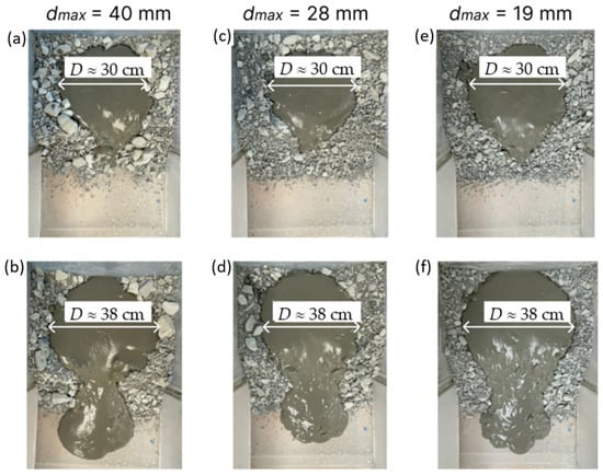
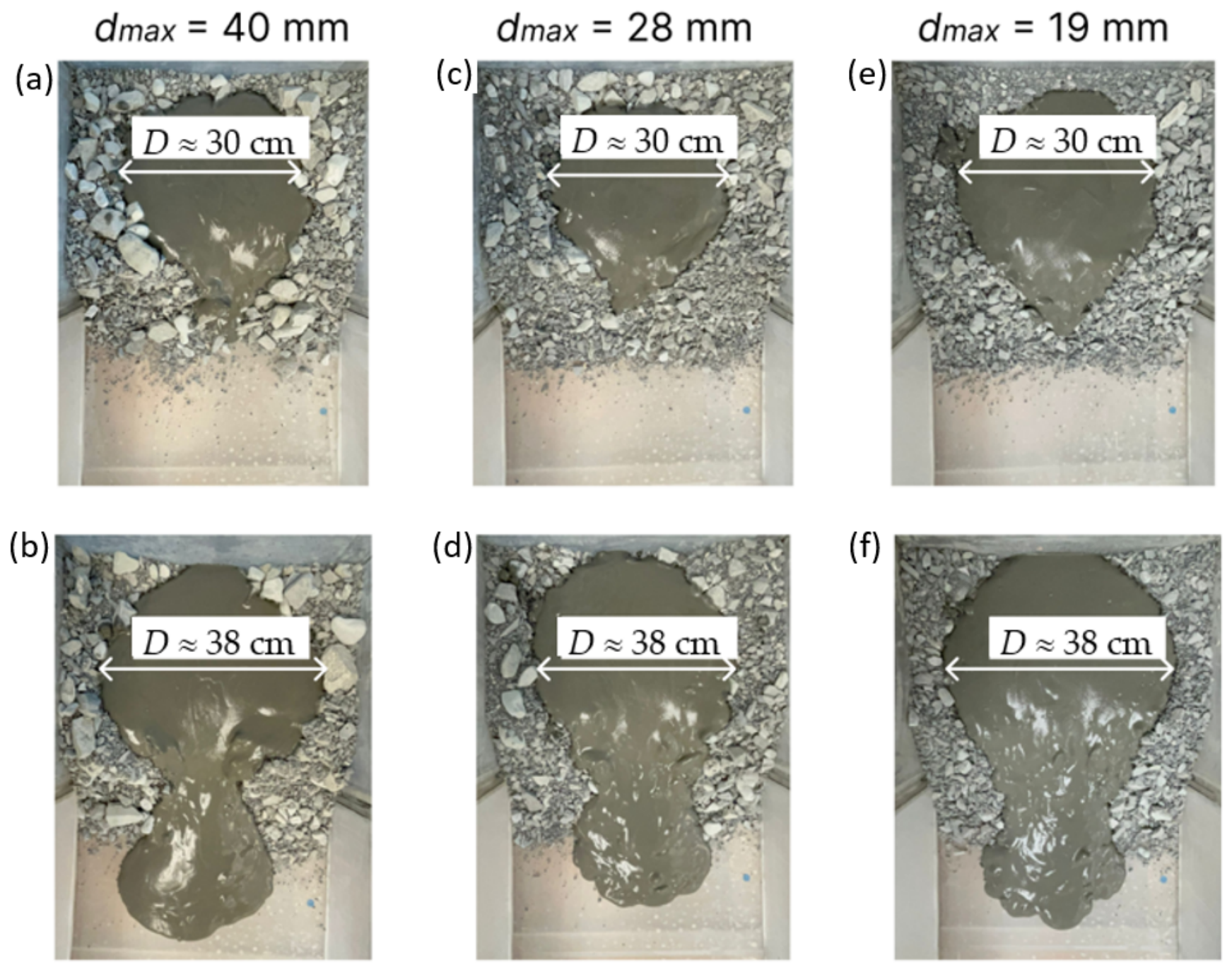
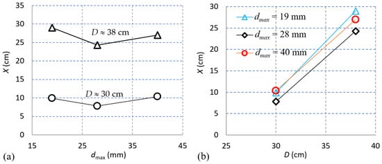
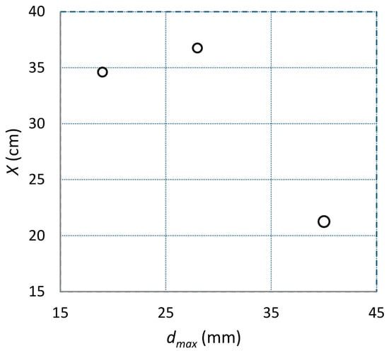
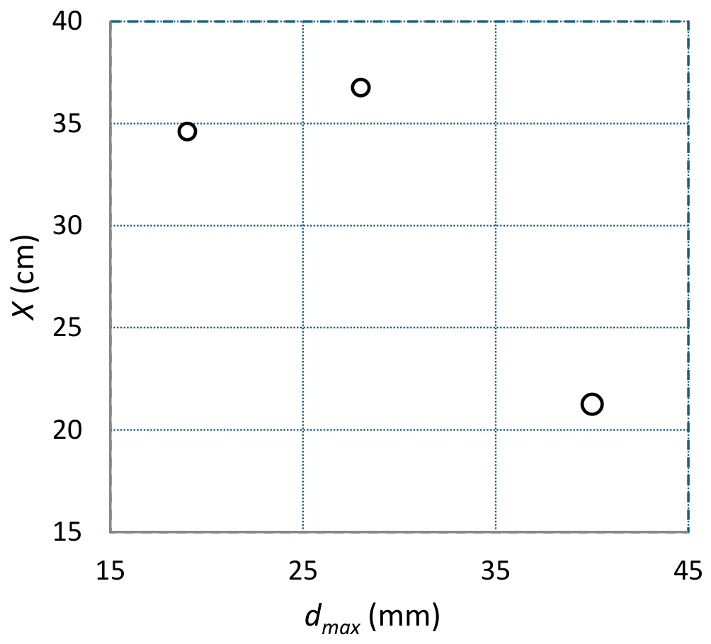
Figure 11 presents photographs of the stabilized tailings flow following the instantaneous failure of the cell, comparing cell diameters (D) of approximately 30 cm (Figure 11a,c,e) and 38 cm (Figure 11b,d,f) for different dmax values of the waste rock. The tailings pulp density was approximately 66%. The results indicate that the runout distance does not change significantly as the waste rock dmax decreases from 40 to 19 mm, suggesting that the tailings runout distance is not sensitive to changes in the dmax of the scalped waste rock samples. This trend is further confirmed by the quantitative results presented in Figure 12a, which differs from that observed for the tailings–waste rock mixture in Section 3.1.
Figure 11.
Photographs of the stabilized tailings flow following the instantaneous failure of a cell with a diameter (D) of approximately 30 cm (a,c,e) and 38 cm (b,d,f) for various dmax values of the waste rock.
Figure 12.
Variation in the tailings runout distance (at a pulp density of approximately 66%) as a function of (a) the waste rock dmax and (b) the waste rock cell diameter (D).
This insensitivity likely arises because the waste rock particles used to construct the cell do not participate in the mixing process upon failure. Furthermore, as the settling time was zero, the improved hydraulic conductivity associated with coarser waste rock did not facilitate accelerated drainage or consolidation of the tailings slurry, thereby rendering the runout distance insensitive to variations in the waste rock dmax. Consequently, this insensitivity, as illustrated in Figure 12a, is consistent with the experimental conditions. Further tests are nonetheless necessary to confirm this conclusion. If this trend is validated by larger-scale testing, it would be possible to predict the runout distance of tailings confined by waste rock under field conditions based on small-scale tests using scalped waste rock samples.
Figure 12b presents the variation in the runout distance as a function of the waste rock cell diameter (D). The results consistently show that the runout distance increases as the cell diameter (D) increases. For a given cell geometry, a larger diameter allows for a greater volume of confined tailings. For a given pulp density, this larger volume inherently leads to a longer runout distance, following the volume-conservation principle implemented in numerical models such as MADflow [30,32].
3.3. Tailings Confined Within a Waste Rock Cell Without Lateral Restrictions
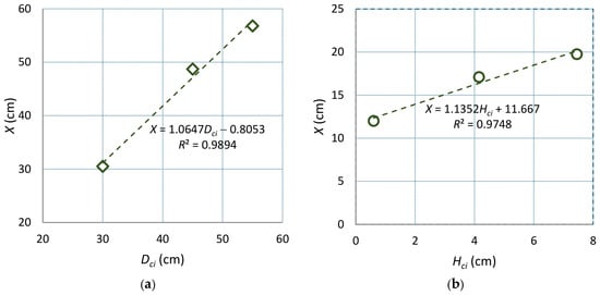
Figure 13 illustrates the variation in the runout distance as a function of the cell internal diameter (Dci) (Figure 13a) and the base layer thickness (Hci) (Figure 13b). The runout distance increases almost linearly with increasing Dci and Hci. With a larger cell internal diameter (Dci), the runout distance is longer because the volume of tailings slurry is larger, thereby sustaining the flow longer. When the base layer thickness (Hci) is greater, the potential energy of the stored tailings is higher. Upon failure, the stored tailings slurry possesses greater kinetic energy, leading to a longer runout distance. These results indicate that Dci and Hci must be limited to prevent the tailings flow from accelerating into a catastrophic release. Crucially, these results were obtained without considering tailings drainage and consolidation through the waste rock. When the base layer thickness (Hci) is insufficient, the downward drainage of the tailings slurry may be restricted. Therefore, optimization is required to determine the optimal thickness (Hci).
Figure 14 presents the variation in the tailings runout distance as a function of the waste rock dmax. No clear correlation could be established between the runout distance and the waste rock dmax. However, these results do not necessarily indicate that the runout distance is insensitive to variations in the dmax of the waste rock, as demonstrated by the large-scale flume tests shown in Figure 12a. Rather, the results generally tend to show that the runout distance decreases as the waste rock dmax increases, even though a larger volume of tailings must be added to completely fill the waste rock cell when the waste rock particles are coarser. One could thus expect a clear decreasing trend in the runout distance with an increasing dmax value if the tests were carried out with the same volume of tailings slurry.
Figure 14.
Runout distance as a function of the waste rock dmax (see Table 2, Case 3).
A plausible explanation for these results can be linked to the testing procedure. A back-analysis of the recorded photographs and videos reveals that a significant delay occurred between tailings slurry pouring and flow triggering. As the cell was relatively large, while the bucket used to pour the tailings slurry was small, filling the cell completely required at least three separate pours. Additionally, instead of failure and subsequent flow being triggered immediately, several tens of seconds elapsed following the completion of the pouring operation. The delay between pouring and abruptly removing the waste rock to trigger the flow varied from several tens of seconds to almost two minutes. During this interval, drainage, consolidation, and the migration of tailings particles through the waste rock envelope occurred [57,58,59,60,61,62]. As the pore sizes, porosity, and hydraulic conductivity increase with an increasing dmax value of the waste rock, more drainage and consolidation of the tailings took place, thereby increasing tailings density, strength, and viscosity, which ultimately led to a shorter runout distance.
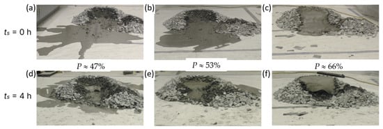
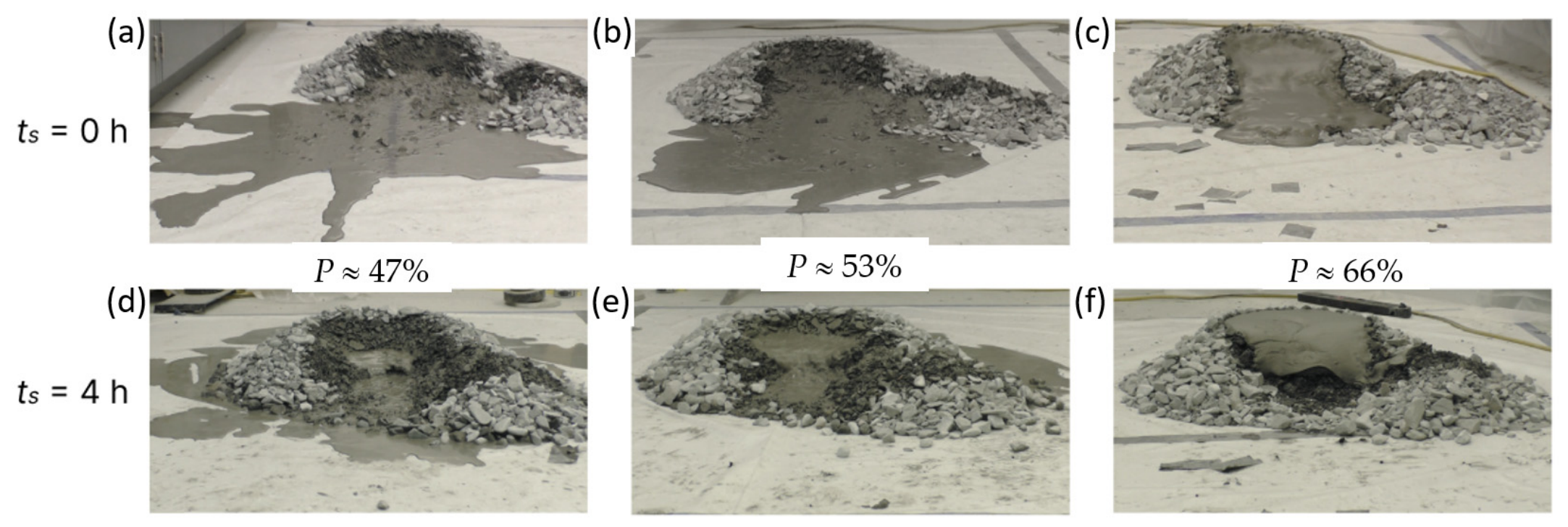
Figure 15 presents the post-failure flow behavior of the tailings after a settling time of 0 h at pulp densities of 47% (Figure 15a), 53% (Figure 15b), and 66% (Figure 15c), as well as after a settling time of 4 h at pulp densities of 47% (Figure 15d), 53% (Figure 15e), and 66% (Figure 15f). As expected, the runout distance decreases with increasing pulp density. A higher pulp density increases the matrix viscosity and flow resistance of the tailings, resulting in a shorter runout distance.
Figure 15.
Influence of ts and P on the unconfined flow behavior of tailings slurry initially confined within a waste rock cell (see Table 2, Case 4): (a–c) after a settling time of 0 h at pulp densities of 47%, 53%, and 66%, respectively; (d–f) after a settling time of 4 h at pulp densities of 47%, 53%, and 66%, respectively.
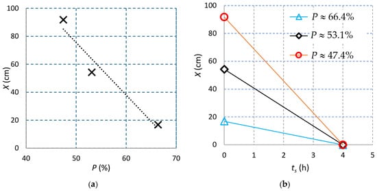
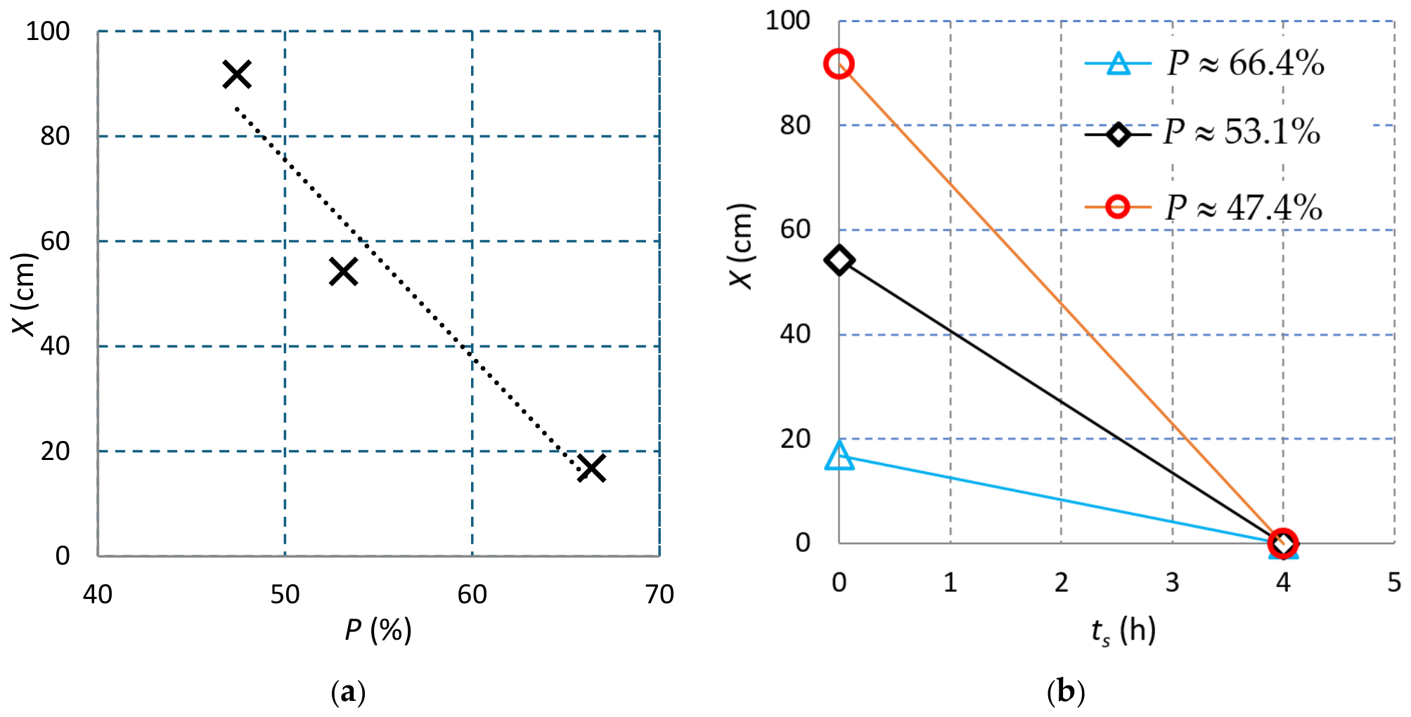
Figure 16 shows the tailings runout distance as a function of the pulp density (P) for different settling times (Figure 16a), and as a function of the settling time for different pulp densities (Figure 16b). The results indicate that the runout distance decreases almost linearly with increasing pulp density (Figure 16a). For a given pulp density, Figure 16b demonstrates that the runout distance decreases significantly as the settling time increases from 0 to only 4 h. This reduction highlights the effective drainage of the tailings slurry through the highly permeable waste rock. However, further experimental work is necessary to describe the variation in X as a function of tf in a more realistic manner.
Figure 16.
Runout distance as a function of (a) tailings pulp density for a 0 h settling time and (b) settling time (ts) for various pulp densities (see Table 2, Case 4).
These trends are consistent with expectations. For a given pulp density, a longer settling time allows for tailings drainage and consolidation [63,64,65,66], which increases tailings density, strength and viscosity. Consequently, upon failure of the confining structure, the increased shear strength and viscosity of the tailings slurry impede flow, yielding a shorter runout distance.
3.4. Comparisons with Existing Empirical Solutions
While studies on the runout distance of co-disposal tailings and waste rock structures are still lacking in the literature, a number of publications have been devoted to estimating the runout distance of tailings flows following the breach of conventional tailings dams [23,24,25,26,27,28,29,30], filtered tailings stacks [31], and waste rock dumps [32,33]. It is therefore of interest to compare the experimental results of this study with these existing solutions.
Rico et al. [25] proposed an empirical solution based on historical tailings dam failure statistics:
where XF (in km) is the runout distance, VF (in Mm3) represents the volume of released tailings, and Hd (in m) designates the tailings dam height at the time of failure.
Subsequently, Larrauri and Lall [27] proposed an improved relationship as follows:
where VT (in Mm3) is the total volume of tailings, with the other parameters being the same as in Equation 1.
Recently, based on historical flow statistics of much larger material flows, Ghahramani et al. [28] proposed a more general empirical solution for a variety of materials as follows:
where Af (in m2) is the inundation area, Vf (in m3) represents the flow volume, and c is a constant. Ghahramani et al. [28] suggested a value of c = 80 for tailings, c = 200 for lahars, c = 12 to 20 for rock avalanches, and c = 17 to 20 for waste dumps and debris flows.
For the first series of flume tests, the runout distance (Xf, in m) can subsequently be derived from Equation (6) as follows:
where w (in m) is the channel width, with w = 0.085 m for the small flume and w = 0.45 m for the large flume. The empirical solution of Ghahramani et al. [28] cannot be applied to the experimental results of the second and third test series because the flow patterns deviated significantly from rectangular geometry, and the irregular flow areas were not measured.
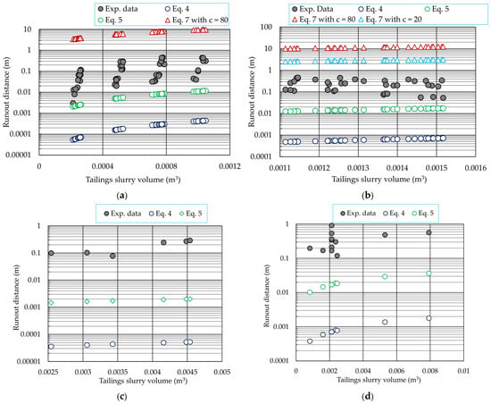
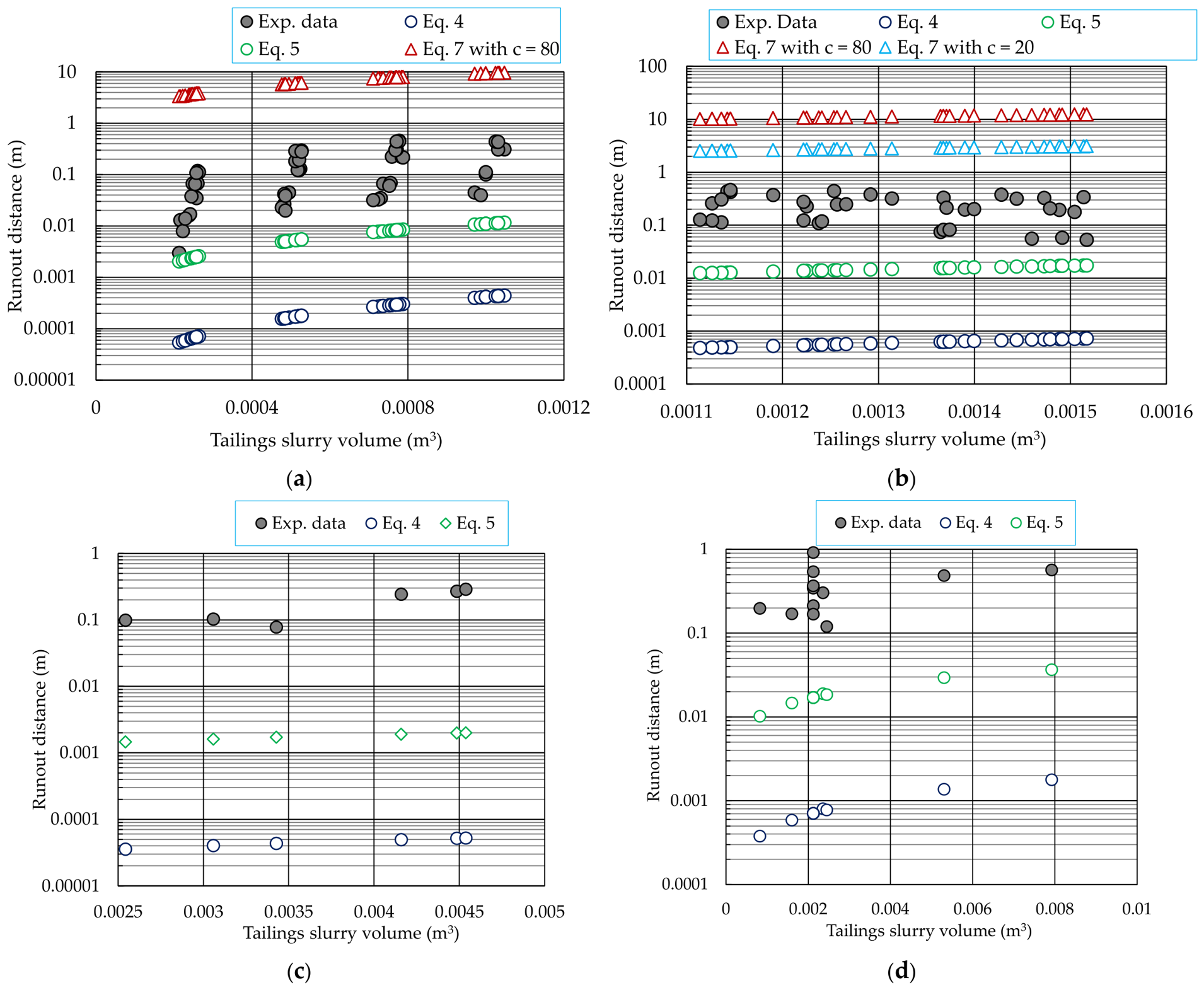
Figure 17 shows the variation in runout distance as a function of the tailings slurry volume obtained from all experimental tests, along with the values predicted by the three empirical solutions, assuming VF = VT. For pure tailings slurry (Figure 17a) and tailings–waste rock mixtures (Figure 17b), predictions using the equations of Rico et al. [25] (Equation (4)), Larrauri and Lall [27] (Equation (5)), and Ghahramani et al. [28] (Equation (7)) were performed by considering Hd = hi. For tailings confined within a waste rock cell in the large flume (Figure 17c), the predictions with these three empirical solutions were obtained using Hd = 0.1 m. Finally, for tailings confined within a waste rock cell without lateral restrictions (Figure 17d), the predictions with the solutions of Rico et al. [25] and Larrauri and Lall [27] were carried out by considering Hd = Hc0.
Figure 17.
Comparison between observed and predicted runout distances as a function of tailings slurry volume under different test conditions: (a) pure tailings slurry (Hd = hi); (b) tailings–waste rock mixtures (Hd = hi); (c) tailings confined within a waste rock cell (Hd = 0.1 m); (d) tailings confined within waste rock without lateral restrictions (Hd = Hc0). All predictions were performed by assuming VF = VT.
In all cases, the empirical solutions of Rico et al. [25] and Larrauri and Lall [27] significantly underestimate the observed runout distances. For pure tailings slurry (Figure 17a) and tailings–waste rock mixtures (Figure 17b), the empirical solutions of Ghahramani et al. [28] significantly overestimate the observed runout distances.
3.5. Migration of Tailings Through Waste Rock
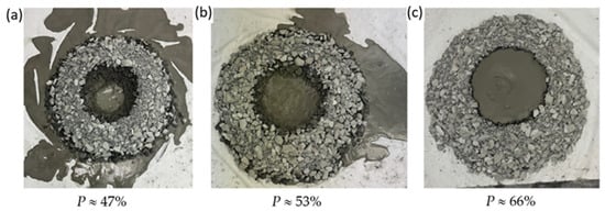
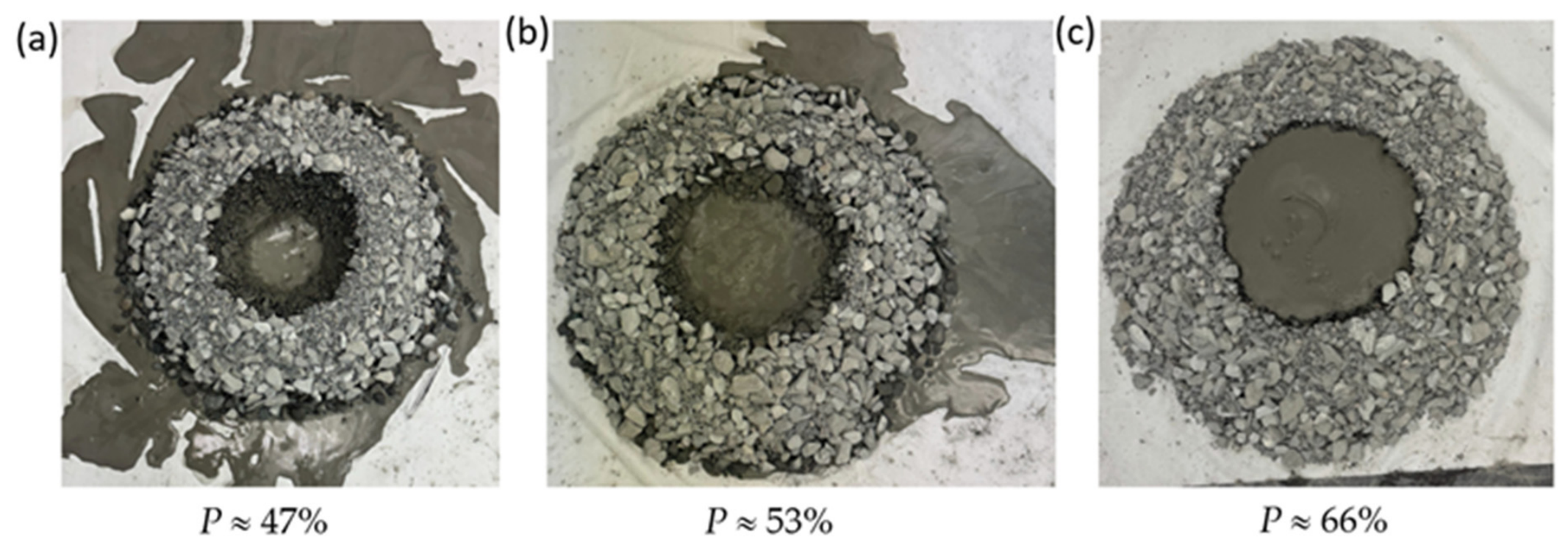
Figure 18 shows the state of the tailings after 4 h of settling before cell breaching. Since no specific measurements were taken to prevent the leakage or migration of tailings through the waste rock cell, significant particle migration of tailings through the waste rock was observed at a pulp density (P) of 47%, whereas this phenomenon was almost absent at a pulp density (P) of 66%. These findings indicate that the migration of tailings particles through waste rock can be controlled or minimized by increasing the pulp density beyond a critical value. Furthermore, the results indicate that conventional filter or retention criteria that solely consider specific particle diameters [67,68,69,70,71,72,73,74], the coefficient of uniformity (Cu) of the base material [75], and particle shapes [76] are insufficient for characterizing the migration of a tailings slurry through waste rock. An extension of classical filter criteria is therefore necessary to incorporate pulp density, the hydraulic gradient, and other influencing factors [59].
Figure 18.
Migration of tailings through waste rock envelope with tailings at pulp densities (P) of (a) 47%, (b) 53%, and (c) 66% after a 4 h settling time (ts).
4. Limitations and Future Studies
In this study, three series of flow tests were conducted to evaluate the influence of tailings–waste rock mixtures and lateral restrictions on the runout distance. The results indicate that waste rock plays a critical role in reducing tailings runout distance. This research contributes to a better understanding and a qualitative evaluation of the different parameters influencing runout behavior. Consequently, these experimental findings are valuable for optimizing the design of integrated CtRS structures. Nevertheless, several limitations inherent to this study should be acknowledged.
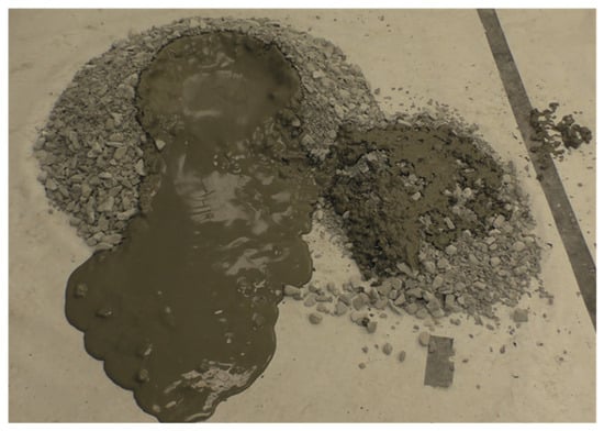
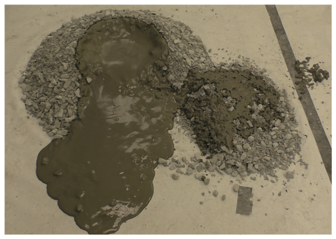
For example, gate lifting, manual waste rock particle removal with a spoon, and single-motion shovel removal do not provide equivalent or easily reproducible failure conditions. Consequently, only a non-significant portion of waste rock particles located adjacent to the flow path was mobilized, as shown in Figure 19. These flow-driven particles settled along the base, thereby increasing the surface roughness for subsequent flow, while the remaining mobilized coarse particles acted as obstacles. Both mechanisms contributed to dissipating the kinetic energy of the tailings flow and reducing the runout distance. More significant mixing between waste rock particles and tailings could be expected if the flow were triggered by the failure of the waste rock slope, instead of completely removing the waste rock at a selected location. Future research should incorporate a mechanically controlled release system to achieve slope failure and better quantification of the breach width.
Figure 19.
Photograph of tailings flow triggered by the single-motion removal of waste rock particles at the front of the cell.
In this study, only two settling times (0 and 4 h) were tested. The reduction in the runout distance is attributed to the effective drainage and consolidation of the tailings slurry facilitated by the pervious waste rock envelope. Further studies are required to better quantify the individual and coupled effects of sedimentation, thixotropic aging, and evaporation in conjunction with these parameters.
Due to the limited availability of the raw materials (tailings and waste rock), a restricted number of runout tests on the co-disposal structures was conducted. Further investigations are necessary to verify the reproducibility of these experimental results.
In this study, the tested co-disposal structure contained only a single cell, whereas the integrated CtRS structure consists of multiple layers with several cells within each layer, as shown in Figure 1. Moreover, the experiments were conducted at a laboratory scale under idealized conditions and therefore cannot fully replicate field-scale conditions, particularly regarding the structural geometry and the waste rock PSD. This limitation stemmed from constraints in the available space and the load-bearing capacity of the experimental facility, making it impractical to replicate full-scale configurations in the laboratory. Therefore, these experiments do not fully reproduce the failure of a full-scale integrated co-disposal facility. Rather, they are simplified laboratory-scale physical models designed to investigate the influence of waste-rock inclusions and tailings properties on post-failure runout behavior. Consequently, the results should be interpreted with caution when applied to the field scale, as scale effects, material heterogeneity, complex failure mechanisms, and site-specific conditions may significantly influence the response of actual co-disposal facilities. Therefore, the present results are intended to provide mechanistic insights rather than direct predictions of field-scale runout distances. The ability of waste rock to restrict tailings mobility, the mechanisms governing tailings migration through waste rock voids, and the parameters controlling the resulting runout distance all require further investigation. Field-scale testing, combined with numerical modeling, is thus necessary to further evaluate the hydraulic and mechanical behavior of CtRS structure under representative field conditions. Future research should focus on:
- Developing reliable numerical models to simulate the failure and flow behavior of integrated CtRS structures;
- Determining the influence of waste rock dmax and hydraulic conductivity on the runout distance to enable field-scale predictions based on laboratory-scale testing;
- Optimizing construction parameters, particularly the WR/T mass ratio and cell geometry, to ensure both safety and economic efficiency;
- Investigating the long-term geotechnical stability of CtRS structures, with a specific focus on the effects of particle migration.
Furthermore, the runout distance is expected to depend on the plasticity, density, and rheological properties of the tailings slurry, as well as the particle shape, density, void ratio, and permeability of the waste rock. These physical, mechanical, and mineralogical properties should be properly characterized in future work to enhance the applicability of the experimental data for quantitative interpretations using numerical or analytical solutions.
It is also necessary to examine the relationships among pulp density, rheological properties, and runout distance by incorporating the Reynolds and Froude numbers to characterize the flow regime and evaluate the scaling similarity between laboratory and field conditions. Additionally, the drainage, consolidation, pore water pressure dissipation, and internal particle migration of the tailings in contact with waste rock should be investigated in future experimental work to quantify their effects on the runout distance.
5. Conclusions
The total co-disposal of chemically non-reactive tailings and waste rock (referred to as CtRS) represents a promising approach to mitigate tailings flow and prevent catastrophic runout in the event of failure. This research experimentally evaluated the influence of several factors on tailings runout distance with or without the addition of waste rock. The following conclusions can be drawn:
- In a homogeneous mixture, waste rock contributes to reducing the runout distance by reinforcing the internal structure of the mixture, particularly at higher pulp densities and waste rock-to-tailings ratios.
- In the waste rock cell configuration, the presence of waste rock dissipates the kinetic energy of the tailings flow by acting as a physical barrier and increasing surface roughness during failure.
- The runout distance increases with both the waste rock cell diameter and the base layer thickness. The former implies that the volume of tailings contained in each cell of the integrated CtRS structure must be limited. The latter must be optimized by considering the trade-off between the increase in tailings potential energy (associated with a greater base layer thickness) and the reduction in drainage capacity (associated with an insufficient base layer thickness).
- The runout distance decreases significantly with an increasing pulp density of the tailings slurry.
- Due to the high permeability and drainage capacity of the waste rock, the runout distance of the tailings slurry can be significantly reduced even with a short settling time.
- The runout distance can be effectively minimized by limiting the size of the waste rock cell, increasing the tailings pulp density, and prolonging the settling time.
- Conventional filter or retention criteria, which solely consider some specific particle diameters for the filter and base materials, are inadequate for characterizing the migration of a tailings slurry through waste rock. An extension of classical filter criteria is therefore necessary to incorporate pulp density, the hydraulic gradient, and other influencing factors.
- This study provides preliminary evidence regarding the mechanisms controlling the runout behavior of tailings and waste rock co-disposal configurations. Further large-scale testing and field investigations are required before these findings can be generalized to full-scale facilities.
Author Contributions
L.H.: methodology, conceptualization, experimentation, analysis, validation, visualization, data curation, writing—original draft; L.L.: methodology, conceptualization, formal analysis, funding acquisition, investigation, project administration, resources, supervision, writing—review. All authors have read and agreed to the published version of the manuscript.
Funding
Natural Sciences and Engineering Research Council of Canada (NSERC, grants RGPIN-2024-06859 and ALLRP 566888-21).
Data Availability Statement
The original contributions presented in this study are included in the article. Further inquiries can be directed to the corresponding author.
Acknowledgments
The authors acknowledge the financial support from the Natural Sciences and Engineering Research Council of Canada (NSERC, grants RGPIN-2024-06859 and ALLRP 566888-21), WSP, and the industrial partners of the Research Institute on Mines and the Environment (RIME UQAT–Polytechnique; https://irme.ca/en/, accessed on 12 November 2026). Special thanks are extended to Patrick Bernèche, Mathieu Robidas, Noura El-Harrak, Éric Tuergons, Samuel Chenier, Abu Hamad, Hamed Bahmani, and Ble Franck Liatche for their lab assistance. The authors also gratefully acknowledge the anonymous reviewers for their critical and constructive comments, which significantly helped improve the quality of this manuscript.
Conflicts of Interest
The authors declare no conflict of interest.
References
- Vick, S.G. Planning, Design, and Analysis of Tailings Dams; Bitech Publisher: Richmond, BC, Canada, 1990. [Google Scholar] [CrossRef]
- Aubertin, M.; Bussière, B.; Bernier, L. Environnement et Gestion des Rejets Miniers; Presses internationales Polytechnique: Montréal, QC, Canada, 2002. [Google Scholar]
- Davies, M.P. Tailings impoundment failures: Are geotechnical engineers listening? Geotech. News 2002, 20, 31–36. [Google Scholar]
- Azam, S.; Li, Q. Tailings dam failures: A review of the last one hundred years. Geotech. News 2010, 28, 50–54. [Google Scholar]
- Lyu, Z.; Chai, J.; Xu, Z.; Qin, Y.; Cao, J. A comprehensive review on reasons for tailings dam failures based on case history. Adv. Civ. Eng. 2019, 2019, e4159306. [Google Scholar] [CrossRef] [Scilit]
- Santamarina, J.C.; Torres-Cruz, L.A.; Bachus, R.C. Why coal ash and tailings dam disasters occur. Science 2019, 364, 526–528. [Google Scholar] [CrossRef] [Scilit] [PubMed]
- Robertson, P.K.; de Melo, L.; Williams, D.J.; Wilson, G.W. Report of the Expert Panel on the Technical Causes of the Failure of Feijão Dam I. 2019. Available online: http://www.b1technicalinvestigation.com (accessed on 12 November 2026).
- WISE. Chronology of Major Tailings Dam Failures. World Information Service on Energy Uranium Project. 2025. Available online: https://www.wise-uranium.org/mdaf.html (accessed on 12 November 2026).
- Jong, H.N. Repeated Failures Expose Gaps in Indonesia’s Nickel Waste Management. Mongabay. 13 April 2026. Available online: https://news.mongabay.com/2026/04/repeated-failures-expose-gaps-in-indonesias-nickel-waste-management/ (accessed on 12 November 2026).
- Emerman, S.H.; Moore, E.; Morrill, J.; Ncube, V.; Personius, P.; Sangadji, A. Filtered Tailings in Indonesia: The Catastrophic Failure of a Disruptive Technology. Earthworks. 25 March 2026. Available online: https://earthworks.org/resources/filtered-tailings-in-indonesia-the-catastrophic-failure-of-a-disruptive-technology/ (accessed on 12 November 2026).
- Wickland, B.E.; Wilson, G.W.; Wijewickreme, D.; Klein, B. Design and evaluation of mixtures of mine waste rock and tailings. Can. Geotech. J. 2006, 43, 928–945. [Google Scholar] [CrossRef] [Scilit]
- Bussière, B. Colloquium 2004: Hydrogeotechnical properties of hard rock tailings from metal mines and emerging geoenvironmental disposal approaches. Can. Geotech. J. 2007, 44, 1019–1052. [Google Scholar] [CrossRef] [Scilit]
- Habte, K.; Bocking, K. Co-Disposal Practices in Mine Waste Management; Golder Associates Ltd.: Mississauga, ON, Canada, 2012. [Google Scholar]
- Leduc, M.; Smith, M. Tailings Co-DisposalTM: Innovations for Cost Savings and Liability Reduction; The Latin America Mining Record: Castle Rock, CO, USA, 2003. [Google Scholar]
- Gowan, M.; Lee, M.; Williams, D.J.; Jewell, R.; Fourie, A.B. Co-disposal techniques that may mitigate risks associated with storage and management of potentially acid generating wastes. In Mine Waste 2010: Proceedings of the First International Seminar on the Reduction of Risk in the Management of Tailings and Mine Waste; Jewell, R., Fourie, A., Eds.; Australian Centre for Geomechanics: Crawley, WA, Australia, 2010. [Google Scholar] [CrossRef] [Scilit]
- James, M.; Aubertin, M.; Bussière, B. On the use of waste rock inclusions to improve the performance of tailings impoundments. In Proceedings of the 18th International Conference Soil Mechanics and Geotechnical Engineering, Paris, France, 2–6 September 2013; pp. 735–738. [Google Scholar]
- Ouellet, S.; Chapuis, S.; Ovalle, C. Le projet de co-deposition dans la fosse Canadian Malartic. In Proceedings of the Symposium Rouyn-Noranda 2021 sur l’environnement et les mines, Rouyn-Noranda, QC, Canada, 14–16 June 2021; Available online: https://publications.polymtl.ca/48109 (accessed on 12 November 2026).
- Behlke, F.; Ovalle, C.; Ouellet, S.; Li, L. Évaluation de la migration des résidus et du comportement hydrogéologique du remblayage par co-déposition dans la fosse de la mine Canadian Malartic. In Proceedings of the Mines and Environment Symposium 2025, Rouyn-Noranda, QC, Canada, 8–11 June 2025; Available online: https://publications.polymtl.ca/67542/ (accessed on 12 November 2026).
- MELCCFP. Directive 019 sur L’industrie Minière. Ministère de l’Environnement, de la Lutte Contre les Changements Climatiques, de la Faune et des Parcs, 15 February 2025. Available online: https://www.environnement.gouv.qc.ca/milieu_ind/directive019/directive-019-2025.pdf (accessed on 12 November 2026).
- Li, L. Études du Comportement Hydrogéotechnique des Structures Intégrales de la Co-Disposition Totale des Résidus Miniers et des Roches Stériles (CtRS) Chimiquement Non-Réactifs; Proposal for NSERC Alliance; PolyPublie: Montréal, QC, Canada, 2020. [Google Scholar]
- Hawley, M.; Cunning, J. Guidelines for Mine Waste Dump and Stockpile Design; CRC Press/Balkema: Leiden, The Netherlands, 2017. [Google Scholar]
- Aubertin, M.; Jahanbakhshzadeh, A.; Yniesta, S. The effect of waste rock inclusions on the seismic stability of a tailings impoundment. In Earthquake Geotechnical Engineering for Protection and Development of Environment and Constructions; CRC Press: Boca Raton, FL, USA, 2019. [Google Scholar]
- Jeyapalan, J.K.; Duncan, J.M.; Seed, H.B. Analyses of flow failures of mine tailings dams. J. Geotech. Eng. 1983, 109, 150–171. [Google Scholar] [CrossRef] [Scilit]
- Jeyapalan, J.K.; Seed, H.B.; Duncan, J.M. Investigation of Flow Failures of Tailings Dams. J. Geotech. Eng. 1983, 109, 172–189. [Google Scholar] [CrossRef] [Scilit]
- Rico, M.; Benito, G.; Díez-Herrero, A. Floods from tailings dam failures. J. Hazard. Mater. 2008, 154, 79–87. [Google Scholar] [CrossRef] [Scilit] [PubMed]
- Rico, M.; Benito, G.; Salgueiro, A.R.; Díez-Herrero, A.; Pereira, H.G. Reported tailings dam failures, A review of the European incidents in the worldwide context. J. Hazard. Mater. 2008, 152, 846–852. [Google Scholar] [CrossRef] [Scilit] [PubMed]
- Larrauri, P.C.; Lall, U. Tailings dams failures: Updated statistical model for discharge volume and runout. Environments 2018, 5, 28. [Google Scholar] [CrossRef] [Scilit]
- Ghahramani, N.; Mitchell, A.; Rana, N.M.; McDougall, S.; Evans, S.G.; Take, A. Tailings-flow runout analysis: Examining the applicability of a semi-physical area–volume relationship using a novel database. Nat. Hazards Earth Syst. Sci. 2020, 20, 3425–3438. [Google Scholar] [CrossRef] [Scilit]
- Vergara, A.; Palma, S.; Álvarez, A.; Zandarín, M.T. Hazards in mining: A novel model for the prediction of run-out distances in tailings dams using CFD. Int. J. Rock Mech. Min. Sci. 2022, 153, 105049. [Google Scholar] [CrossRef] [Scilit]
- Chen, H.J.; Cunning, J. A practical tool for tailings dam breach analysis—Numerical modelling of hydraulic erosion and discharge of flowable tailings. Sci. Total Environ. 2025, 980, 179467. [Google Scholar] [CrossRef] [Scilit] [PubMed]
- Roman, B.; Barreto, A.; Villanueva, M. Assessment of the run-out distance of filtered dry stacked tailings using the Material Point Method. In Proceedings of the Tailings and Mine Waste 2025, Banff, AB, Canada, 2–5 November 2025. [Google Scholar]
- Chen, H.J.; Cunning, J. Case Study of Flowslides for Mine Waste Dumps from Mobilization to Runout. In Proceedings of the Tailings and Mine Waste 2025, Banff, AB, Canada, 2–5 November 2025. [Google Scholar]
- Tiwari, A.; Tyeb, M.H.; Mandal, B.B.; Pathak, P.; Tewari, M. Experimental investigation on mobility and deposition characteristics of granular and poly-dispersed mine overburden dump material in inclined channels for hazard assessment. Geomat. Nat. Hazards Risk 2025, 16, 2483803. [Google Scholar] [CrossRef] [Scilit]
- ASTM D7928-21e1; Standard Test Method for Particle-Size Distribution (Gradation) of Fine-Grained Soils Using the Sedimentation (Hydrometer) Analysis. ASTM International: West Conshohocken, PA, USA, 2021.
- ASTM D6913/D6913M-17; Standard Test Methods for Particle-Size Distribution (Gradation) of Soils Using Sieve Analysis. ASTM International: West Conshohocken, PA, USA, 2025.
- ASTM D854-02; Standard Test Methods for Specific Gravity of Soil Solids by Waster Pycnometer. ASTM International: West Conshohocken, PA, USA, 2017.
- Deiminiat, D.; Li, L.; Zeng, F.; Pabst, T.; Chiasson, P.; Chapuis, R. Determination of the Shear Strength of Rockfill from Small-Scale Laboratory Shear Tests: A Critical Review. Adv. Civ. Eng. 2020, 1, 8890237. [Google Scholar] [CrossRef] [Scilit]
- Deiminiat, A.; Li, L. Experimental study on the reliability of scaling down techniques used in direct shear tests to determine the shear strength of rockfill and waste rocks. CivilEng 2022, 3, 35–50. [Google Scholar] [CrossRef] [Scilit]
- Zhang, Y.; Li, L. Experimental study on the natural mixing behaviour of waste rocks poured in a paste backfill. Int. J. Min. Reclam. Environ. 2023, 37, 953–977. [Google Scholar] [CrossRef] [Scilit]
- Zhang, Y.; Li, L. Optimization of discrete element method model to obtain stable and reliable numerical results of mechanical response of granular materials. Minerals 2024, 14, 758. [Google Scholar] [CrossRef] [Scilit]
- Kazemi, P.; Li, L. An Empirical Solution for Estimating the Maximum Allowable Mass of Waste Rock to Prevent Non-Mixing Between Paste Backfill and Dumped Waste Rock. Minerals 2026, 16, 676. [Google Scholar] [CrossRef] [Scilit]
- Zhang, Y.; Li, L.; Ouellet, S.; Gélinas, L.P. Numerical and experimental studies of the natural mixing behavior between an uncemented paste backfill and dumped waste rock in stopes from laboratory toward field conditions. Part I: Calibration and validation of a numerical model. Deep. Resour. Eng. 2026, 3, 100232. [Google Scholar] [CrossRef] [Scilit]
- Zhang, Y.; Li, L.; Gélinas, L.P.; Ouellet, S. Numerical and experimental studies of the natural mixing behavior between an uncemented paste backfill and dumped waste rock in stopes from laboratory toward field conditions. Part II: Application and prediction of the validated and calibrated numerical model. Deep. Resour. Eng. 2026, 3, 100236. [Google Scholar] [CrossRef] [Scilit]
- Paynter, J.T.; Dodd, J.C. The Design, Commissioning and Operation of the Golden Giant Paste Backfill Plant. In Proceedings of the 29th Annual Meeting of the Canadian Mineral Processors (Division of the CIM), Ottawa, ON, Canada, 21–23 January 1997; pp. 382–403. [Google Scholar]
- Hassani, F.; Archibald, J. Mine Backfill. In CD-ROM Manual; CIM: Westmount, QC, Canada, 1998. [Google Scholar]
- Potvin, Y.; Thomas, E.; Fourie, A. Handbook on Mine Fill; Australian Centre for Geomechanics: Crawley, WA, Australia, 2005. [Google Scholar]
- Desriviers, P.; Quintero, A.; Primeau, P. Effects of the mineralogical composition and particle size distribution on the rheology of gold and copper tailings. In Proceedings of the Paste 2019; Paterson, A.J.C., Fourie, A.B., Reid, D., Eds.; Australian Centre for Geomechanics: Perth, WA, Australia, 2019; pp. 505–514. [Google Scholar]
- Dias, N.A.; Moreira Pires, P.J.; Soares, E.J. Rheological Characterization of Tailing Pastes from Ore Mining. Min. Metall. Explor. 2026, 43, 905–914. [Google Scholar] [CrossRef] [Scilit]
- Zhang, M.; Zhang, Q.; Zhang, H.; Shang, X.; Tan, X.; Jiang, Z.; Lin, Y.; Shu, J.; Ma, T.; Shen, L. Rheology of Paste in Mine Backfilling: Mechanisms, Models, and Key Influencing Factors. Fluid Dyn. Mater. Process. 2026, 22, 4. [Google Scholar] [CrossRef] [Scilit]
- Hane, I.; Belem, T.; Benzaazoua, M.; Maqsoud, A. Laboratory investigation into the compressive strength of cemented paste tailings aggregate fills. In Proceedings of the Underground Mining Technology 2017; Hudyma, M., Potvin, Y., Eds.; Australian Centre for Geomechanics: Perth, WA, Australia, 2017; pp. 363–374. [Google Scholar]
- Yu, D.; Tang, L.; Chen, C. Three-dimensional numerical simulation of mud flow from a tailing dam failure across complex terrain. Nat. Hazards Earth Syst. Sci. 2020, 20, 727–741. [Google Scholar] [CrossRef] [Scilit]
- Liu, L.; Song, K.-I.; Lao, D.; Kwon, T.-H. Rheological Properties of Cemented Tailing Backfill and the Construction of a Prediction Model. Materials 2015, 8, 2076–2092. [Google Scholar] [CrossRef] [Scilit]
- Zhang, X.; Wang, H.; Wu, A. Study on Correlations between Tailings Particle Size Distribution and Rheological Properties of Filling Slurries. Minerals 2023, 13, 1134. [Google Scholar] [CrossRef] [Scilit]
- Cai, J.; Sun, C.; Zhang, J.; Wang, B.; Ran, J.; Tang, N. Study on the Rheological Properties and Microstructural Evolution Mechanism of Multicomponent Solid Waste Cementitious Slurry. Materials 2026, 19, 994. [Google Scholar] [CrossRef] [Scilit] [PubMed]
- Panchal, S.; Deb, D.; Sreenivas, T. Mill tailings based composites as paste backfill in mines of U-bearing dolomitic limestone ore. J. Rock Mech. Geotech. Eng. 2018, 10, 310–322. [Google Scholar] [CrossRef] [Scilit]
- Kasap, T.; Yilmaz, E.; Sari, M. Physico-chemical and micro-structural behavior of cemented mine backfill: Effect of pH in dam tailings. J. Environ. Manag. 2022, 314, 115034. [Google Scholar] [CrossRef] [Scilit] [PubMed]
- Essayad, K.; Pabst, T.; Chapuis, R.P.; Aubertin, M. An experimental study of tailings migration through waste rock inclusions. In Proceedings of the GeoEdmonton 2018; Canadian Geotechnical Society: Surrey, BC, Canada, 2018. [Google Scholar]
- Essayad, K.; Aubertin, M. Consolidation of hard rock tailings under positive and negative pore-water pressures: Testing procedures and experimental results. Can. Geotech. J. 2020, 58, 49–65. [Google Scholar] [CrossRef] [Scilit]
- Essayad, K. Évaluation Multi-Échelle de L’instabilité Interne et de la Migration des Résidus à Travers les Inclusions de Roches Stériles. Ph.D. Thesis, École Polytechnique de Montréal, Montréal, QC, Canada, 2021. [Google Scholar]
- Behlke, F.; Ovalle, C.; Li, L. Experimental investigation of drainage and consolidation of tailings slurry in a co-disposal structure. In Proceedings of the GeoMontreal, 2024; Canadian Geotechnical Society: Surrey, BC, Canada, 2024. [Google Scholar]
- Behlke, F.; Ovalle, C.; Ouellet, S.; Li, L. Experimental investigation of mine tailings migration through waste rock in co-disposal structures. In Proceedings of the Tailings and Mine Waste, Banff, AB, Canada, 2–5 November 2025. [Google Scholar]
- Behlke, F.; Ovalle, C.; Ouellet, S.; Li, L. Evaluation of tailings migration and hydrogeological behaviour in co-disposal backfilling of the Canadian Malartic mine pit. In Proceedings of the Mines and Environment Symposium 2025, Rouyn-Noranda, QC, Canada, 6–11 June 2025; CIM: Westmount, QC, Canada, 2025. [Google Scholar]
- Nguyen, N.D.; Pabst, T.; Razavi, S.K.; Jahanbakhshzadeh, A. 3D numerical study of the consolidation of tailings co-disposed with waste rocks in open pits: Development, validation and application. In Proceedings of the GeoMontreal 2024, 77th Canadian Geotechnical Conference, Montréal, QC, Canada, 15–18 September 2024. [Google Scholar]
- Nguyen, N.D.; Pabst, T. Numerical Study of Consolidation of Slurry Tailings Considering Continuous Update of Material Properties. Geotech. Geol. Eng. 2024, 42, 3251–3267. [Google Scholar] [CrossRef] [Scilit]
- Nguyen, N.D.; Pabst, T. Consolidation behavior of various types of slurry tailings co-disposed with waste rock inclusions: A numerical study. Environ. Earth Sci. 2023, 82, 65. [Google Scholar] [CrossRef] [Scilit]
- Nguyen, N.D.; Pabst, T. Acceleration of Consolidation of Tailings in a Pit Using Waste Rocks Co-disposal. Geotech. Geol. Eng. 2024, 42, 1593–1609. [Google Scholar] [CrossRef] [Scilit]
- Terzaghi, K. Failure of dam foundations by piping and means for preventing it. Wasserkr. Z. Gesamte Wasserwirtsch. 1922, 17, 445–449. (In German) [Google Scholar]
- Bertram, G. An Experimental Investigation of Protective Filters; National Academies: Washington, DC, USA, 1940. [Google Scholar]
- Lafleur, J.; Mlynarek, J.; Rollin, A.L. Filter criteria for well graded cohesionless soils. In Filters in Geotechnical and Hydraulic Engineering; Brauns, J., Heibaum, M., Schuler, U., Eds.; Balkema: Cape Town, South Africa, 1993; pp. 97–106. [Google Scholar]
- Sherard, J.L.; Dunnigan, L.P. Critical filters for impervious soils. J. Geotech. Eng. 1989, 115, 927–947. [Google Scholar] [CrossRef] [Scilit]
- Foster, M.A.; Fell, R. Assessing embankment dam filters that do not satisfy design criteria. J. Geotech. Geoenviron. Eng. 2001, 127, 398–407. [Google Scholar] [CrossRef] [Scilit]
- Locke, M.; Indraratna, B. Filtration of broadly graded soils: The reduced PSD method. Géotechnique 2002, 52, 285–287. [Google Scholar] [CrossRef] [Scilit]
- Fell, R.; MacGregor, P.; Stapledon, D.; Bell, G. Geotechnical Engineering of Dams; Taylor & Francis: London, UK, 2005. [Google Scholar] [CrossRef] [Scilit]
- Vakili, A.H.; Selamat, M.R.B.; Aziz, H.B.A. Filtration of broadly graded cohesive dispersive base soils. J. Geotech. Geoenviron. Eng. 2015, 141, 04015004. [Google Scholar] [CrossRef] [Scilit]
- USACE. Filter Experiments and Design Criteria; Army Engineer Waterways Experiment Station: Vicksburg, MS, USA, 1953. [Google Scholar]
- Rather, N.A.; Lone, M.A.; Dar, A.Q.; Eslamian, S.; Mir, B.H.; Dar, B.A. Design criteria of protective filters based on particle shape and gradation parameters. Int. J. Hydrol. Sci. Technol. 2020, 10, 102–122. [Google Scholar] [CrossRef] [Scilit]

Disclaimer/Publisher’s Note: The statements, opinions and data contained in all publications are solely those of the individual author(s) and contributor(s) and not of MDPI and/or the editor(s). MDPI and/or the editor(s) disclaim responsibility for any injury to people or property resulting from any ideas, methods, instructions or products referred to in the content. |
© 2026 by the authors. Licensee MDPI, Basel, Switzerland. This article is an open access article distributed under the terms and conditions of the Creative Commons Attribution (CC BY) license.