


Abstract
This study investigates the influence of unsteady heat and mass transfer processes on the formation of gas composition and thermal conditions in a large cross-section (132 m2) blind-end chamber of a gypsum mine during the operation of diesel-powered mining equipment, including a front-end loader representing the LHD class and a dump truck. The modeled system considers a chamber where the LHD operates continuously, while the dump truck enters periodically to perform haulage cycles. Ventilation is provided from an adjacent panel haulage drift using a booster fan. Numerical simulations were carried out using ANSYS Fluent within the RANS framework, employing the realizable k-ε turbulence model, with consideration of thermal and gas convection. A dynamic mesh approach was applied to explicitly represent the motion of the dump truck. Both steady-state scenarios, corresponding to extreme equipment positions, and a fully transient case involving dump truck entry into the chamber followed by idling were analyzed. The results demonstrate that the movement of the dump truck generates a pronounced piston effect, which alters the jet flow structure and temporarily increases the supply of fresh air to the working face. It is shown that steady-state assumptions based on prolonged equipment presence near the face overestimate the total NOx concentration within the large chamber and may not adequately reflect actual gas conditions over typical loading cycle durations. The analysis of unsteady processes using the dynamic mesh approach reveals significant inertia in contaminant accumulation within the chamber. This finding enables a more accurate estimation of the required airflow rate, reducing excessive safety margins compared to calculations based on the assumption of continuous equipment operation near the face.
1. Introduction
Ensuring safe working conditions in underground mines during the operation of equipment powered by internal combustion engines (ICE) remains one of the most critical challenges in mine ventilation engineering [1,2]. Traditional ventilation design methods, based on steady-state balances of airflow, gas concentrations, heat, and averaged dilution factors, do not account for the complex spatiotemporal dynamics of exhaust gas dispersion and heat transfer. These dynamics are strongly influenced by the motion of mining equipment, the turbulent wakes it generates [3], and associated thermal effects [4].
To achieve a more detailed representation of gas–air mixture transport processes within mine workings, three-dimensional numerical modeling based on computational fluid dynamics (CFD) has become increasingly widespread [5,6]. This progress has been enabled by rapid advances in computational power, as well as improvements in turbulence modeling, numerical algorithms, and simulation software.
A distinct area within the study of blind-end ventilation concerns investigations that account for unsteady processes, particularly those associated with the movement of mining equipment. One of the first systematic studies combining field measurements with three-dimensional CFD modeling that explicitly considered moving mining vehicles was presented in [7], based on experiments conducted at the Missouri S&T experimental mine and industrial sites in the United States. In that work, the species transport model in ANSYS Fluent was validated using data on diesel particulate matter (DPM) dispersion. It was shown that even for properly maintained engines, DPM concentrations in exhaust gases range from 7 to 10 ppm, while for malfunctioning engines they may reach 35 ppm. DPM does not mix instantaneously with the intake airflow, forming persistent contaminant plumes with concentrations exceeding regulatory limits (160 µg/m3) in zones near the exhaust outlet and at distances of 10–20 m downstream, even at high airflow rates in haulage drifts.
Further development of this approach was presented in [8], where a dynamic mesh method was applied for the first time to simulate the shuttle motion of a dump truck in a through mine opening. The authors identified and described three critical unsteady effects not observed in steady-state simulations: (1) a piston effect generating local reverse-flow zones of exhaust gases against the main airflow; (2) buoyancy-driven stratification of DPM under the roof due to heated gases; and (3) displacement of the contaminant plume and peak concentration zone to the driver’s breathing level at vehicle speeds exceeding 3 m/s. It was demonstrated that vehicle motion in the same direction as the ventilation airflow is significantly more hazardous than opposing motion due to repeated accumulation of contaminant concentrations during acceleration and deceleration.
Similar patterns were confirmed in [3] for blind headings in coal mines using monorail locomotives with ICEs. The authors showed that in “aerodynamic shadow” zones along the sides of the locomotive and in stagnant regions behind obstacles, DPM accumulates with concentrations exceeding 1.2⋅10−7 kg/m3 over periods of 15–60 s, while peak contamination (2.91⋅10−7 kg/m3) occurs at a distance of 33 m from the face.
The extension of the dynamic mesh approach to microclimate analysis was presented in [9], where simulation of a continuous mining system in blind headings of deep potash mines demonstrated that accounting for variable heat loads and the motion of shuttle cars is essential for the design of air conditioning systems. The motion of the shuttle car and the associated piston effect temporarily disrupt the ventilation airflow structure, while periodic switching of the cutting machine motors on and off significantly affects the temperature field in the near-face zone.
A separate class of problems concerns the aerodynamic influence of large hoisting conveyances. In [10], the piston effect caused by cage movement in a mine shaft and its impact on ventilation in adjacent haulage drifts were investigated. Using a dynamic mesh approach, it was shown that low-velocity vortex zones in the wake of the cage during counterflow motion generate reverse currents and vortex structures extending up to 70 m from the shaft, reducing the pressure drop in the working by 8.6–11.1 Pa. This disrupts airflow distribution within the ventilation network and necessitates adjustments in main fan operation.
Dynamic mesh techniques have also been applied to assess the influence of unsteady turbulent flow on the dynamic stability of moving conveyances in vertical mine shafts [11,12]. In [11], unsteady airflow distribution in a skip shaft with rope guides was analyzed under conditions of two conveyances in motion. It was shown that the amplitude of transverse oscillations of the conveyances, partially constrained by flexible rope guides, strongly depends on whether their motion is explicitly considered: simulations assuming stationary conveyances underestimate maximum loads by 30–45%, making such approaches unsuitable for evaluating dynamic behavior during operation. Studies [11,12] further demonstrated that oscillation characteristics of moving conveyances in rope-guided shafts depend, among other factors, on the Coriolis force, which can only be captured through explicit modeling of conveyance motion.
Modern studies clearly demonstrate that unsteady aerodynamic effects induced by moving equipment in underground mines cannot be adequately described using steady-state models. The application of dynamic mesh techniques in CFD simulations enables identification of critical contamination zones, optimization of ventilation system parameters, and justified reduction in excessive safety margins in airflow rates through more accurate physical modeling. This forms the basis for improving overall energy efficiency of mine ventilation systems, advancing the concept of ventilation on demand [13], and transitioning from shift-based ventilation control to adaptive systems that integrate both artificial intelligence methods and a deeper understanding of unsteady mass transfer processes [14,15].
The influence of unsteady ventilation effects is particularly pronounced in large cross-section chambers. As the volume of the ventilated space increases, the processes of contaminant accumulation and removal become significantly more inertial [14]. In the presence of even localized heat sources, increasing chamber height leads to a nonlinear intensification of thermal convection [4,15]. At the same time, existing studies mainly address the influence of a single machine on unsteady ventilation in workings with cross-sectional areas up to 30 m2 [10,16,17], which does not allow for a comprehensive characterization of aerodynamic effects specific to large-section chambers. Moreover, the interaction of two or more machines under such conditions remains insufficiently investigated.
In the present study, we investigate airflow and contaminant transport in the working area of a gypsum mine with a cross-sectional area of 132 m2, where a load–haul–dump (LHD) machine operates continuously and a dump truck performs periodic haulage cycles. The aim of the study is to assess how the ventilation behavior of such a chamber changes when transitioning from steady-state consideration of extreme scenarios (truck present in the chamber/truck absent) to a fully transient analysis using a dynamic mesh approach.
The main novelty of this study is that it demonstrates how the motion of heat- and pollutant-emitting mining equipment shapes the transient airflow and contaminant distribution in a large-section blind-end chamber. The work applies a dynamic mesh technique, still rarely used in mine ventilation, to explicitly resolve equipment motion and its impact on unsteady heat and mass transfer.
2. Study Area and Methods
The object of this study is the ventilation system and ventilation processes in mine workings of a gypsum mine operating the Novomoskovskoye deposit at a depth of approximately 120–130 m.
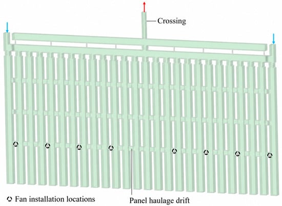
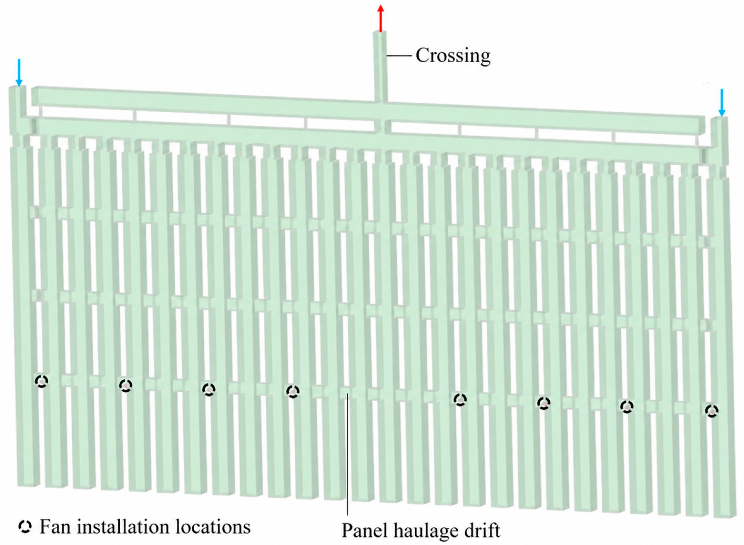
The mine employs a room-and-pillar mining method with rib pillars left between chambers and a protective roof layer. A characteristic feature of this method is the variability of roadway parameters depending on the thickness of the water-protective strata, while all openings are characterized by large cross-sectional dimensions, which directly affect airflow patterns and contaminant distribution in the mine atmosphere. Entries have a rectangular cross-section with widths up to 12 m and heights up to 11 m. Such large dimensions promote the formation of extensive stagnant zones and vertical stratification of contaminants, which must be taken into account in ventilation design. The width of haulage–ventilation crosscuts, where mining equipment is directly operated, does not exceed 8.5 m, with heights ranging from 6.5 to 11 m (see Figure 1).
Figure 1.
Geometry of the gypsum mine panel. Blue arrows indicate the fresh-air supply to the panel, whereas red arrow indicates the return airflow carrying contaminated air away from the panel.
Mining is carried out using the drill-and-blast method with heavy diesel-powered mobile equipment, including Liebherr 566T front-end loaders (Liebherr-Werk Bischofshofen GmbH, Bischofshofen, Austria), CAT R2900 LHD machines (Caterpillar Inc., Irving, TX, USA), and articulated Bell B45E dump trucks (Bell Equipment Ltd., Richards Bay, South Africa). In the present CFD study, the near-face loading operations are represented by a simplified geometric model of a front-end loader (Liebherr 566T class) and a Volvo A40G dump truck (Volvo Construction Equipment, Gothenburg, Sweden) with dimensions and exhaust characteristics typical of the dump trucks used at the mine. Blind-end chambers where equipment operates have lengths up to 70 m, creating conditions for the formation of stagnant zones and accumulation of exhaust gases (NOx, CO) in case of insufficient ventilation.
A central (U-tube) forcing ventilation system is implemented at the mine, which determines the configuration of ventilation equipment and airflow directions. The mine is classified as non-hazardous with respect to gas and dust.
Fresh air from the main fan is supplied to the panels. Auxiliary fans installed in the panel haulage drift generate a high-velocity air jet that intensifies mass transfer and turbulent mixing of flows within the drift and at chamber entrances [18,19]. These booster fans (types VM-6 and VM-8) operate without ventilation stoppings directly within the cross-section of the opening. The VM-6 unit has the following specifications: power 25 kW, airflow rate 16.0 m3/s, total pressure 2500 Pa. Structurally, the unit includes a fan and a Venturi tube with a diffuser (diameter 1.4 m). The fans are installed sequentially along the panel haulage drift and at intersections with crosscuts, creating directed airflow due to the ejection effect (see Figure 1). The return airflow, containing diesel exhaust and blasting products, is removed from the panel haulage drift through ventilation entries via crosscuts toward the shafts.
When formulating the problem of ventilating a large cross-section blind-end chamber from gases emitted by diesel-powered equipment, the following assumptions were adopted:
- The density of the gas–air mixture varies with temperature according to the ideal gas law (Mendeleev–Clapeyron equation).
- Chemical reactions between gases are neglected; gaseous species are treated as passive scalars.
- The realizable k-ε turbulence model is used to simulate turbulent flows generated by auxiliary fans and moving vehicles, as well as the diffusion of NOx and CO.
The mathematical formulation of the problem involves solving the Reynolds-averaged Navier–Stokes (RANS) equations closed with the realizable k-ε turbulence model, which has proven effective for simulating jet flows and separation zones behind obstacles (e.g., mining equipment):
where are indices of the coordinate directions taking values 1, 2, 3 (corresponding to the axes); are spatial coordinates , m; are velocity components, m/s; is time, s; is density, kg/m3; is pressure, Pa; is turbulent kinetic energy, m2/s2; and are the molecular and turbulent dynamic viscosities of the gas–air mixture, Pa·s; is the Kronecker delta, is the gravity vector, m/s2, which in this problem is directed vertically downward (, , ). The gravity term in (2), combined with variable air density, makes it possible to account for thermal and buoyancy-driven gas convection in the air space of the mine workings.
The turbulence equations are written as:
where is the turbulent Prandtl number for ; is the turbulent Prandtl number for ; is the dissipation rate of turbulent kinetic energy, m2/s3; is the production of turbulent kinetic energy due to mean velocity gradients, kg/(m·s3); is the kinematic molecular viscosity, m2/s; is the strain-rate tensor, s−1; are empirical model constants; is the turbulence source term accounting for near-wall effects, kg/(m·s3). In this study, the Menter–Lechner near-wall treatment is employed.
According to our previous studies, the realizable k-ε model outperforms other two-parameter closures when simulating structurally complex turbulent airflows and provides more robust convergence for flows involving rotation, boundary layers with strong adverse pressure gradients, separation and recirculation. These features are crucial for the present problem, which includes jet ventilation, large recirculation zones and the unsteady piston effect induced by moving mining vehicles.
The variation in air temperature in the roadway is governed by the energy equation:
where T is temperature, °C; is the effective thermal conductivity, W/(m·K); is the specific total energy of the gas mixture, J/kg.
The numerical solution of the ventilation problem for the large cross-section blind-end chamber with diesel exhaust was obtained using ANSYS Fluent 2021 R2. A pressure-based solver was employed, and coupling between pressure and velocity was handled with the SIMPLE algorithm. The PRESTO scheme was used for pressure discretization, while second-order schemes were applied for all other variables. The computational domain was discretized with a hexahedral mesh including prism layers near walls; the total number of cells was 8.435 million.
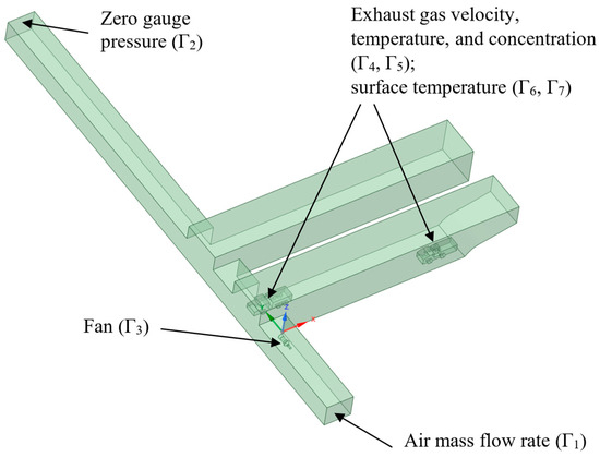
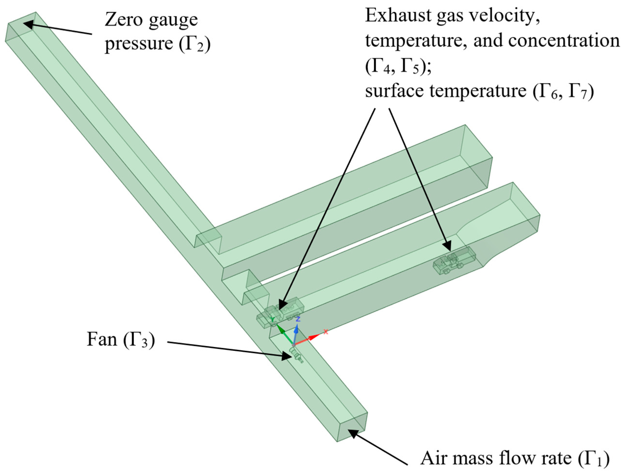
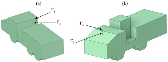
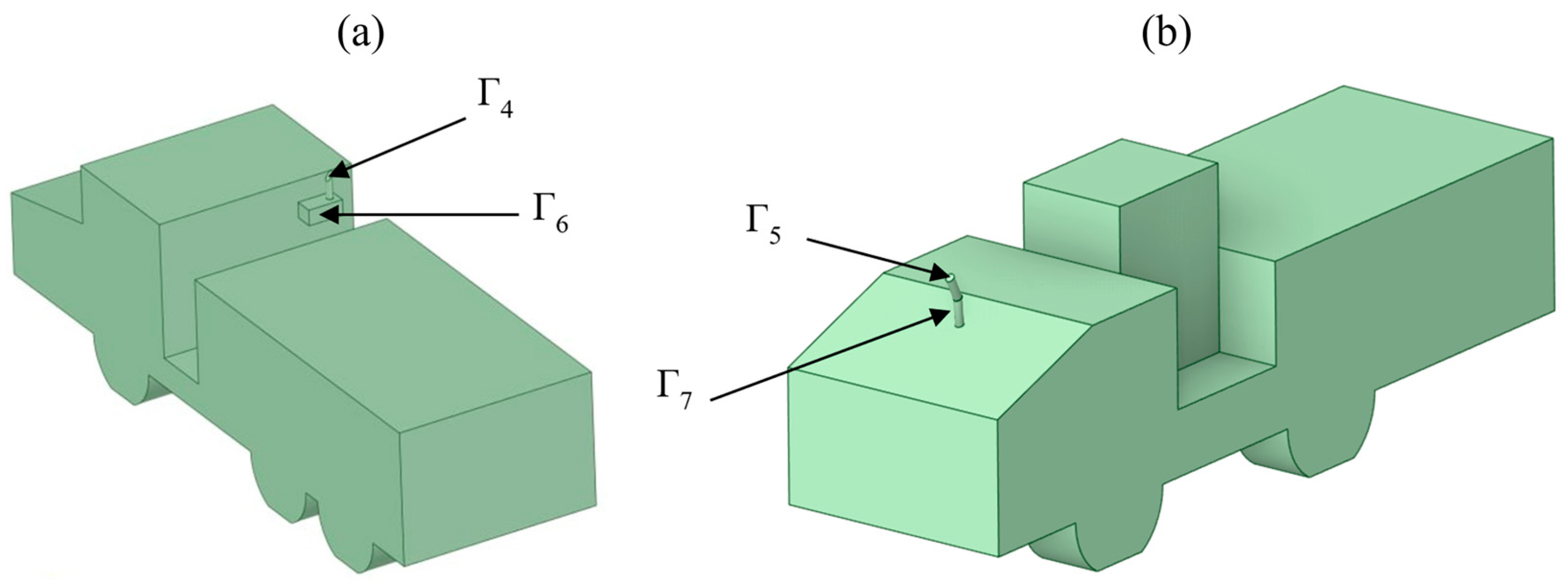
Figure 2 shows the geometry of the computational domain with the surfaces where boundary conditions were prescribed. In this work, not the entire panel was modeled, but a selected segment of the haulage drift with two blind-end chambers, each 70 m long. The cross-section of the haulage drift has a rectangular profile 11 m high and 12 m wide. The blind-end chambers are modeled as rectangular prisms with a cut at the face to represent a rock fall-out. In the first blind-end chamber, two machines are located: a Volvo A40G dump truck and a Liebherr 566T loader. To account for heat release and exhaust emissions from the machines, simplified geometric models of the dump truck and loader were developed (see Figure 3).
Figure 2.
Geometry of the model and notation of surfaces Γi with prescribed boundary conditions.
Figure 3.
Simplified geometric model of the dump truck (a) and loader (b).
The numerical model was parameterized using field measurements collected by the authors at the gypsum mine that served as the study site. The key ventilation and exhaust parameters obtained from these in situ measurements, and subsequently used as input data for the simulations, are summarized in Table 1.
Table 1.
Experimental measurements in the mine workings.
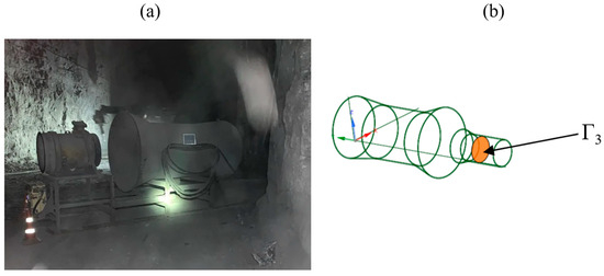
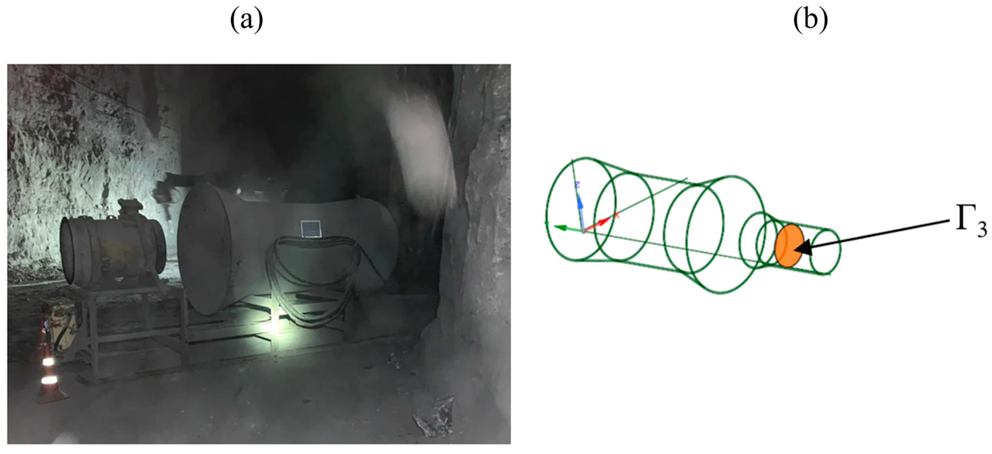
In addition to the general ventilation of the workings, represented by appropriate inlet and outlet boundary conditions on the haulage drift, auxiliary ventilation was also taken into account. An auxiliary ventilation fan is installed in front of the first blind-end chamber at a height of 1.3 m (height to the center of the circular fan cross-section). The fan geometry is shown in Figure 4.
Figure 4.
Auxiliary booster fan: photograph of the actual underground installation (a) and simplified geometric model (b).
The pressure rise across the fan (boundary Γ3) was specified as a quadratic function of the airflow velocity:
where is the magnitude of the air velocity vector prescribed normal to the fan surface, m/s.
At the inlet to the haulage drift (boundary Γ1), the air mass flow rate was set to 27 kg/s (corresponding to an airflow of 1350 m3/min). At the outlet of the drift (boundary Γ2), a zero gauge pressure condition was imposed, modeling free outflow from the computational domain.
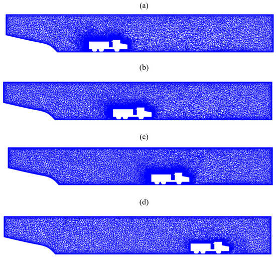
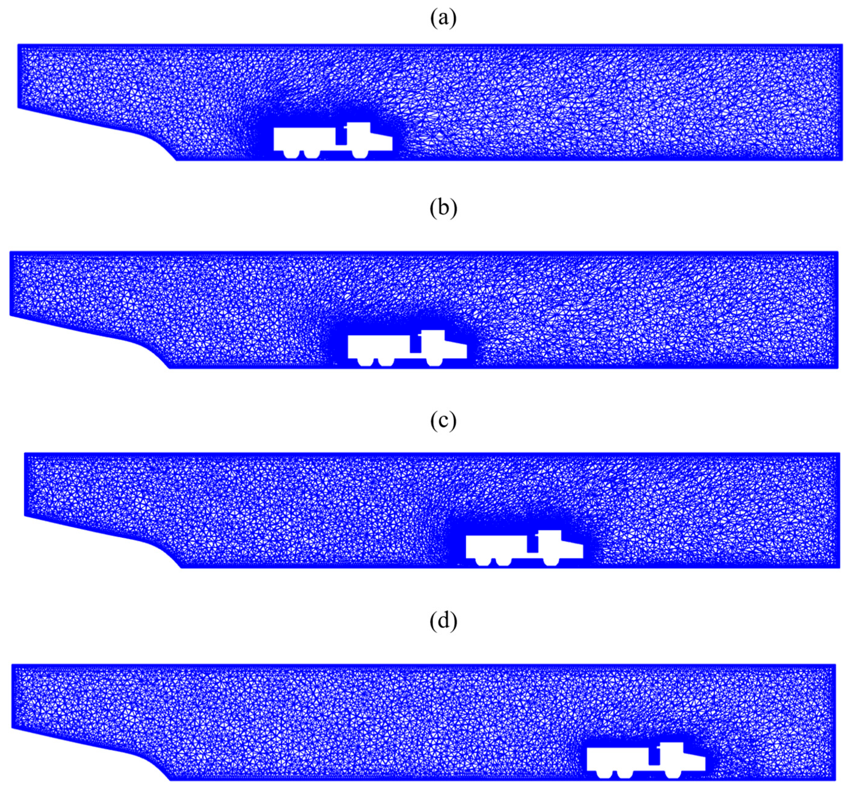
To simulate dump truck motion in the blind-end chamber, the Dynamic Mesh approach was used, providing automatic updating and correction of deforming cells in the computational domain at each time step. Mesh motion was treated using the ALE (Arbitrary Lagrangian–Eulerian) framework, which enables efficient handling of moving boundaries while preserving mesh quality. A combination of diffusion-based smoothing for gradual redistribution of cell deformation and local remeshing with element reconstruction at every second time step was applied, ensuring solution stability under large boundary displacements. An example of mesh evolution at different times is shown in Figure 5.
Figure 5.
Computational mesh in a vertical longitudinal section of the blind-end chamber in the region of the dump truck; parts (a–d) show the mesh at different time instants.
To model exhaust emissions at the outlets of the exhaust pipes of the mining machines, fixed gas velocity, concentration, and temperature were prescribed (boundaries Γ4 and Γ5). The velocity vector was set normal to the outlet cross-section:
where n is the outward normal to the surface; is the velocity vector, m/s; is the velocity component normal to the surface representing the exhaust gas outflow. A no-penetration condition is imposed on all other solid surfaces.
Boundary conditions for the gas mixture composition at the exhaust outlets (boundaries Γ4 and Γ5) were specified via species mass fractions calculated from the initial NOx and CO concentrations. The mass fraction values prescribed at the exhaust sources were:
- Dump truck: and ;
- Loader: and .
These parameters define the proportion of each species in the total exhaust gas mixture.
A constant temperature was specified at the exhaust pipe outlets:
where Texh is the exhaust gas temperature for both the dump truck and the loader.
Heat release from the exhaust system was taken into account by prescribing a fixed temperature on the external surfaces of the engine compartments (boundaries Γ6 and Γ7):
where Teng is the surface temperature of the dump truck and loader engines. Heating of the surrounding air in the model occurs through convective heat transfer as the airflow passes over these surfaces.
At the mine working walls, a similar boundary condition to expressions (8) and (9) was applied, with a constant rock mass surface temperature of 12 °C (see Table 1).
A detailed mesh convergence analysis was carried out for the steady-state configuration in which the dump truck is located at the entrance to the first blind-end chamber. Two monitoring quantities were selected: the maximum air velocity of the jet entering the chamber and the maximum air velocity along the panel haulage drift. Six hexahedral meshes with prism layers near the walls were generated, with the total number of cells ranging from 3.95 million to 13.01 million. As shown in Table 2, starting from the mesh with approximately 8.44 million cells, both monitored velocities become practically insensitive to further refinement. The maximum jet velocity in the chamber varies from 4.42 m/s to 4.39 m/s when the cell count is increased from 8.44 to 13.9 million, while the maximum drift velocity changes from 16.10 m/s to 15.99 m/s, corresponding to relative differences below 1%. On this basis, the mesh with 8.44 million cells was adopted for all subsequent steady-state and transient simulations as providing an optimal balance between numerical accuracy and computational cost.
Table 2.
Mesh convergence study for the steady-state case with the dump truck at the chamber entrance.
In the transient simulations with moving equipment, an adaptive time-stepping strategy was employed. The time increment was primarily controlled by mesh deformation criteria to prevent deterioration of mesh quality between successive remeshing operations. As the dump truck moved through the chamber, the time step was automatically reduced in regions of intense mesh distortion; in the most demanding phases of the motion, the minimum time step reached 8 × 10⁻⁴ s. This constraint was more restrictive than the usual Courant condition applied in transient convection–dominated flows, so that the convective Courant number remained well below unity throughout the computational domain. Under these conditions, the transient solution did not exhibit any numerical instabilities associated with mesh motion, and the temporal resolution was sufficient to capture the piston-induced airflow fluctuations and contaminant transport.
3. Results and Discussion
The first stage of the study involved steady-state numerical simulation of heat and mass transfer in the blind-end chamber. This was followed by unsteady simulations with explicit representation of mining equipment motion. Steady and unsteady results were then compared to identify characteristic features arising when unsteady processes are taken into account. A separate part of the work, presented below, is an assessment of the gas accumulation rate in the blind-end chamber, obtained from the transient simulation results.
3.1. Steady-State Simulation
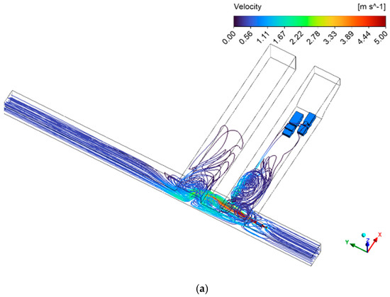
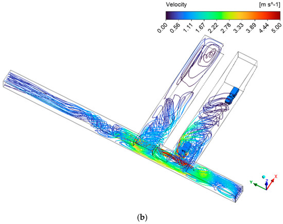
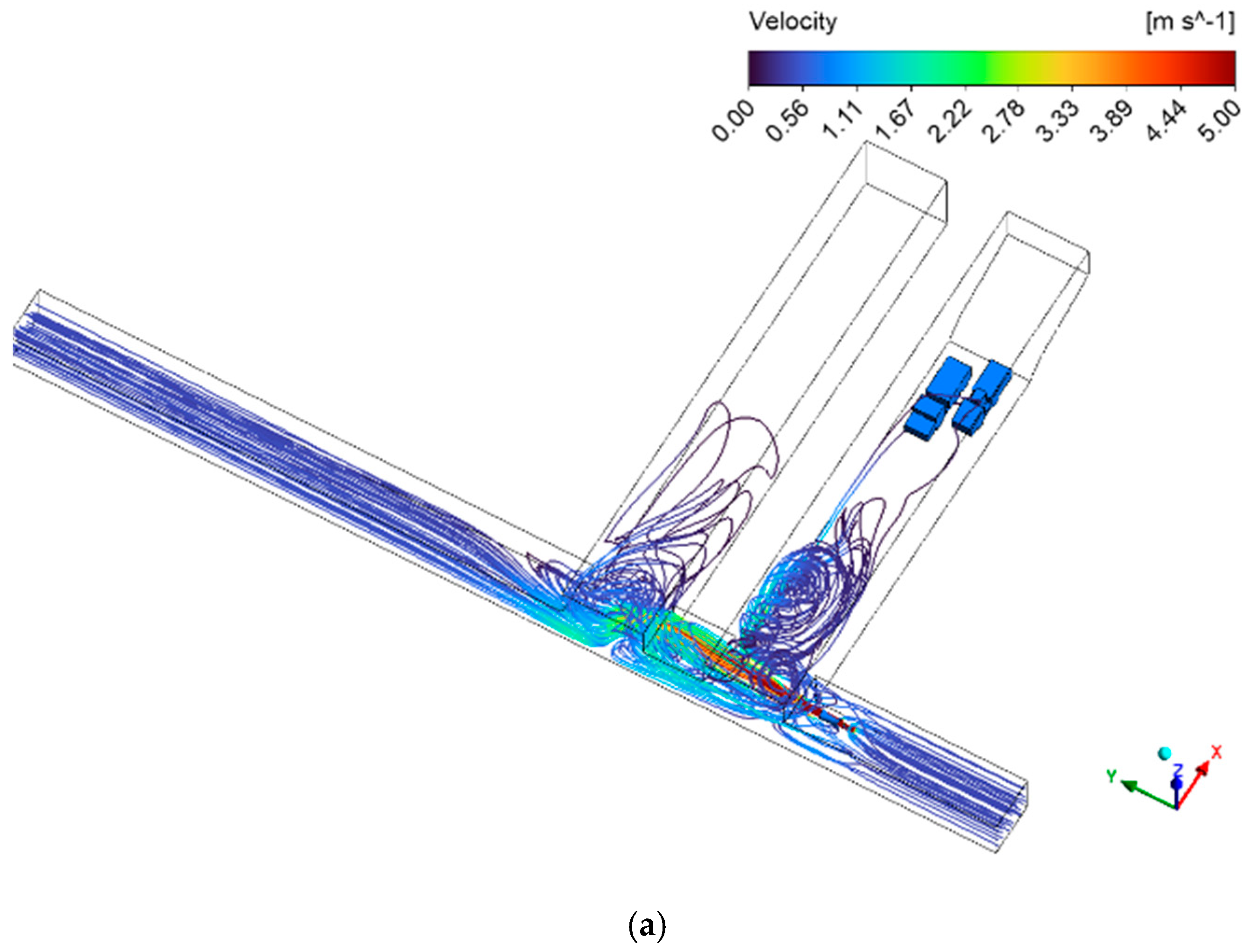
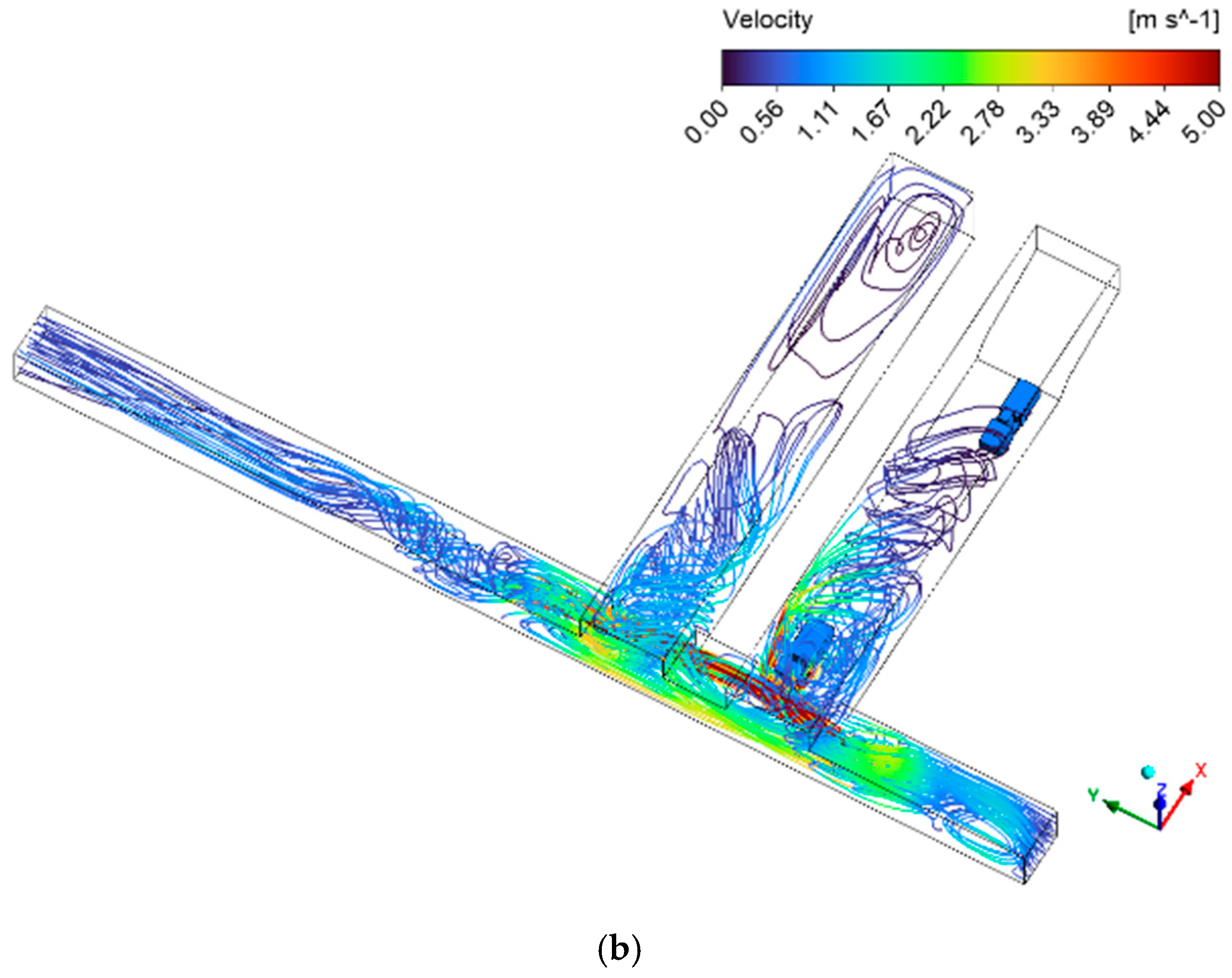
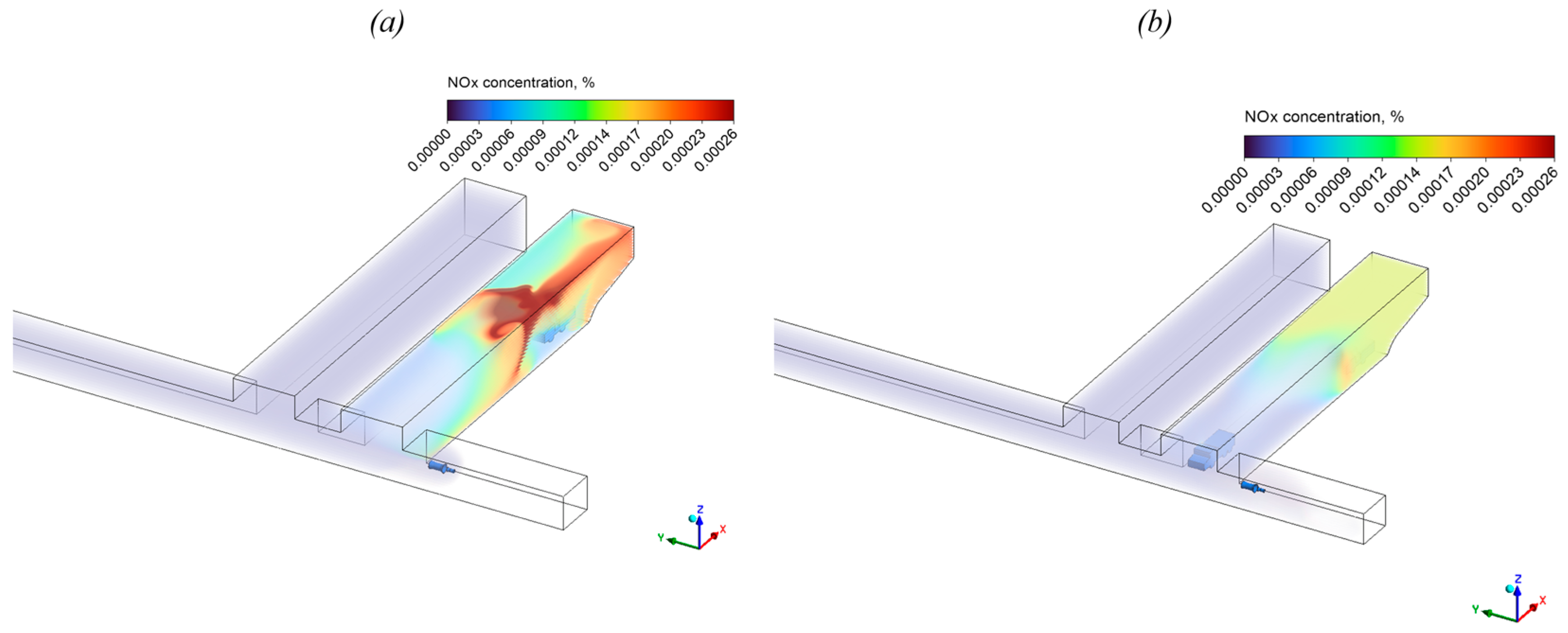
For the steady-state analysis, two cases were considered: (1) the dump truck and the loader are both located inside the chamber near its entrance; (2) the dump truck is positioned at the chamber entrance, while the loader is located inside the chamber. The numerical results for these two configurations, shown in Figure 6 and Figure 7, demonstrate a pronounced influence of the dump truck position on the airflow structure in the chamber and in the panel haulage drift.
Figure 6.
Airflow streamlines colored by velocity magnitude: dump truck at the face (a); dump truck exiting the chamber (b).
Figure 7.
NOx concentration distribution within the chamber volume: dump truck at the face (a); dump truck exiting the chamber (b).
Streamlines colored by air velocity magnitude (Figure 6) show that a dump truck exiting the chamber substantially modifies and effectively “breaks up” the ventilation jet. As a result, part of the jet is directed more intensively into the first chamber, and the flow in the second chamber is also somewhat enhanced. It should be noted that in both cases the jet penetration distance remains limited, and a recirculation zone forms in the vicinity of the fan in the panel haulage drift.
With regard to gas conditions, steady-state simulations reveal extensive stagnant zones in the deeper part of the chamber, especially near the face. This leads to localized regions of elevated concentrations of exhaust contaminants in the immediate vicinity of the exhaust outlets, as well as under the roof of the opening (in the case where both units of equipment are positioned at the face; see Figure 7a). Local exceedances of NOx concentration are particularly pronounced for case no. 1, when both machines are located near the chamber entrance. In case no. 2, most of the contaminants emitted by the dump truck are immediately carried out of the chamber into the panel haulage drift (see Figure 7b).
It is important to note that the present study also analyzed CO concentration distributions in the blind-end chamber. However, the simulations showed that in all steady-state scenarios the CO concentration remained within acceptable limits (below 0.0017%), and therefore the corresponding results are not presented graphically. Overall, analysis of the two limiting equipment configurations indicates that a steady-state approach, which neglects vehicle motion and the dynamics of contaminant accumulation and removal, yields a gas distribution that is strongly dependent on the instantaneous equipment position.
3.2. Transient Simulation
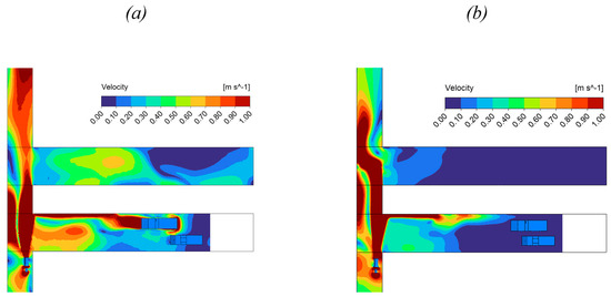
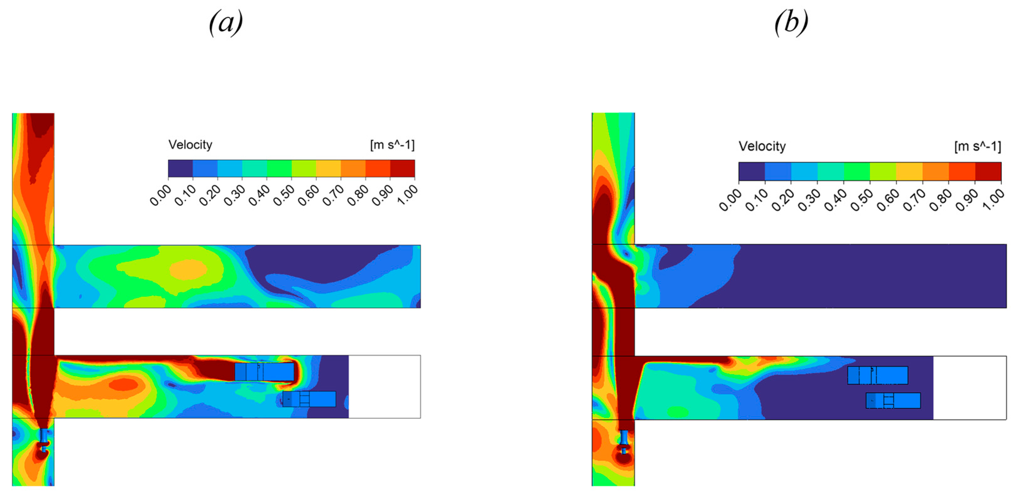
The second part of the study was devoted to simulating dump truck motion in reverse, from the chamber entrance to the loading position, at a speed of 1.94 m/s (7 km/h). The main results are presented in Figure 8 and Figure 9.
Figure 8.
Velocity distribution in a horizontal section at a height of 1.3 m above the floor of the workings: transient simulation at the moment when the dump truck has approached the loader at the chamber entrance (a); steady-state simulation with the dump truck stationary next to the loader (b).
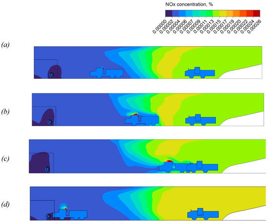
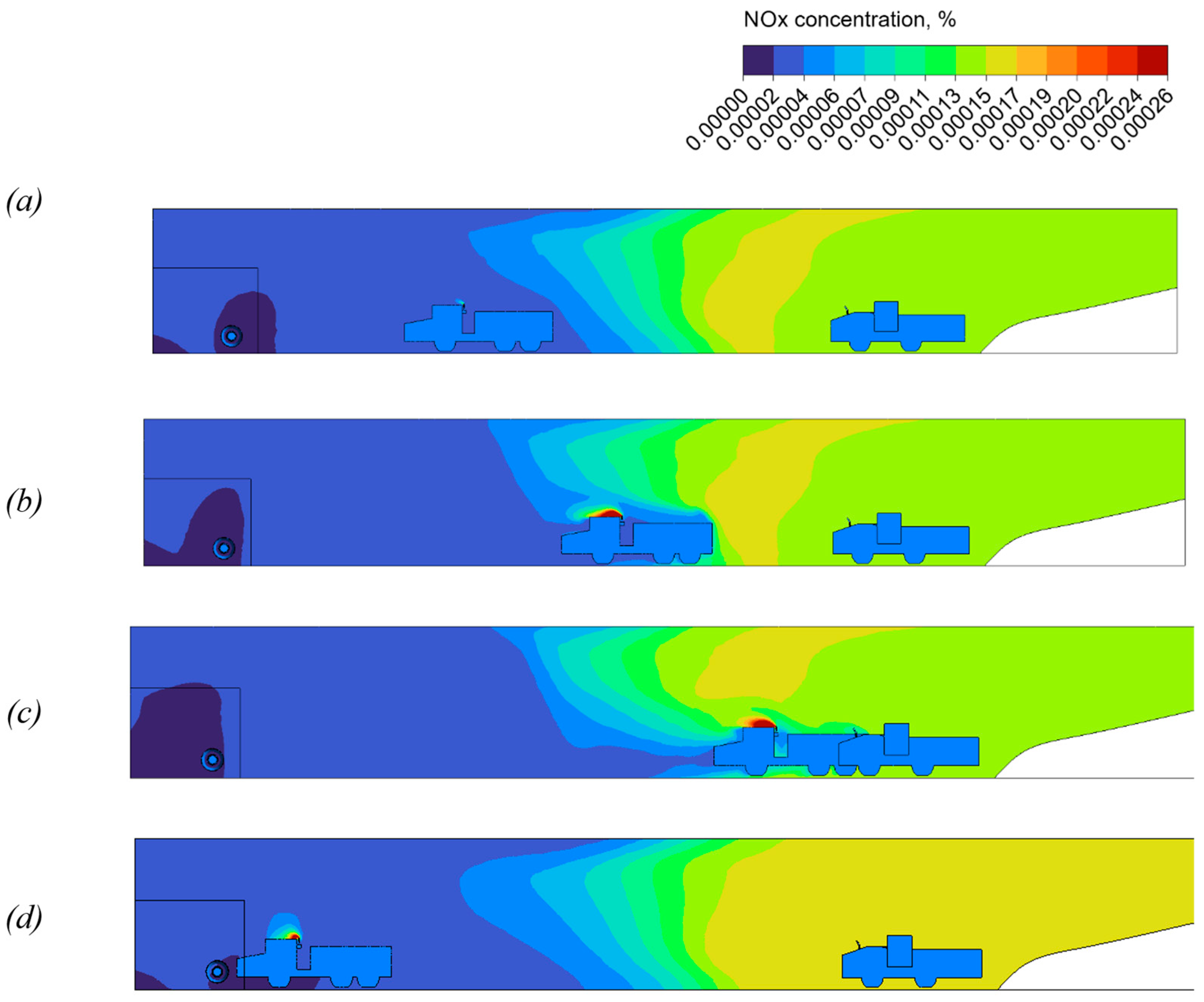
Figure 9.
NOx concentration distribution in a section passing through the dump truck exhaust stack: (a) transient simulation, dump truck has traveled 12 m; (b) transient simulation, 24 m; (c) transient simulation, 36 m; (d) steady-state simulation, dump truck at the chamber entrance.
Visualization of the velocity field during vehicle motion (Figure 8) shows that the moving dump truck acts as a piston. A comparison of the plots demonstrates that the transient velocity field within the chamber is substantially more intense than in the steady-state case. As the vehicle moves, the co-current airflow in the chamber cross-section, directed from the entrance toward the face, undergoes pronounced fluctuations that reflect the reorganization of the aerodynamic flow structure behind the moving obstacle.
The key differences between the transient and steady-state approaches are also evident in the NOx concentration distribution at the driver’s cab level (Figure 9). Analysis of NOx concentrations in a vertical section passing through the exhaust stack and the driver’s cab of the dump truck shows that, on average, the transient simulation yields lower contaminant concentrations in the chamber air volume compared with steady-state case no. 2, where the dump truck is positioned at the chamber entrance and the loader is located inside the chamber near the face (Figure 9d). Over the considered time interval, the transient simulation also predicts lower contaminant levels than in steady-state case no. 1, where the dump truck is located near the face.
The reason for this behavior is that over the relatively short time interval (about 20 s while the dump truck moves from the entrance to the face), the overall transient gas distribution pattern does not have time to adjust from situation 2 to situation 1. Therefore, despite the presence of two machines in the chamber, the concentration fields remain closer to steady-state situation 2, when the dump truck is located near the chamber exit: the distribution of contaminants simply does not have time to reorganize, since this would require a time interval on the order of the air exchange time in the chamber, , where is the chamber volume (about 132 m2 in cross-section and 70 m in length) and is the average airflow rate (on the order of 10 m3/s). At the same time, the moving dump truck generates a piston effect, entraining part of the air mass and producing a slight positive effect over the considered time interval: the mean NOx concentrations in Figure 9 are somewhat lower than in Figure 7b. At the same time, local exceedances of permissible concentrations persist near the exhaust outlet (in the upper part of the vehicle).
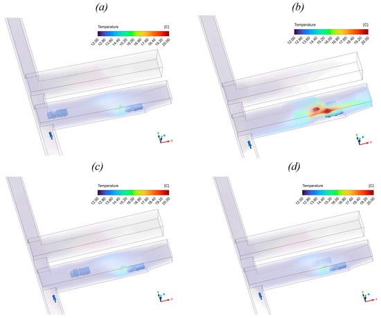
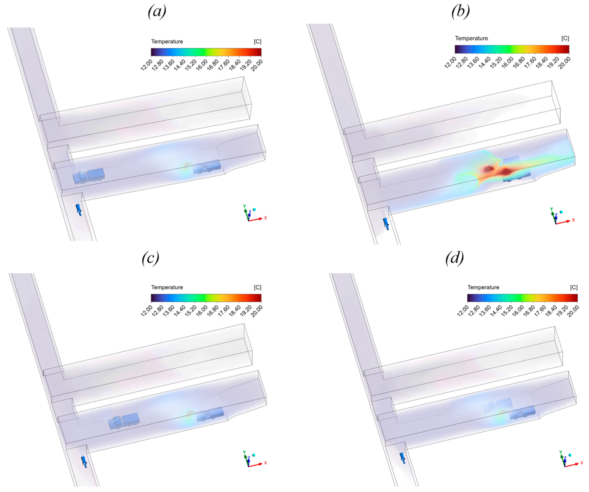
An analogous effect is observed for the temperature field dynamics as well. Figure 10 presents volume renderings of the temperature field in the computational domain for four different scenarios.
Figure 10.
Volume rendering of the temperature field in the computational domain for steady-state and transient scenarios of dump truck positioning in the blind-end chamber: steady-state simulation with the dump truck at the chamber entrance (a); steady-state simulation with the dump truck stationary next to the loader (b); transient simulation with the dump truck having traveled 12 m (c); and transient simulation with the dump truck having traveled 36 m (d).
The figure shows that, on average, the temperature field in both transient cases remains close to that of the steady-state scenario with the dump truck at the chamber entrance. The amount of heat required for the system to approach the state shown in Figure 10b simply does not have time to be released during the period in which the dump truck travels toward the loader at the chamber entrance.
The modeled transient scenario does evolve toward a quasi-steady regime similar to the solution obtained in Section 3.1, but only over a much longer time scale, comparable to the air exchange time in the blind-end chamber. Analysis of this process is presented in the following subsection, Section 3.3.
3.3. Transient Solution over a Longer Time Period
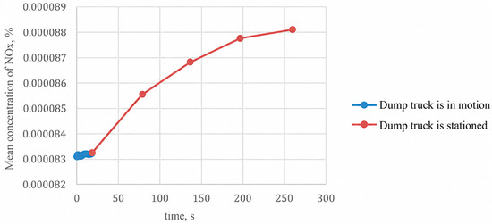
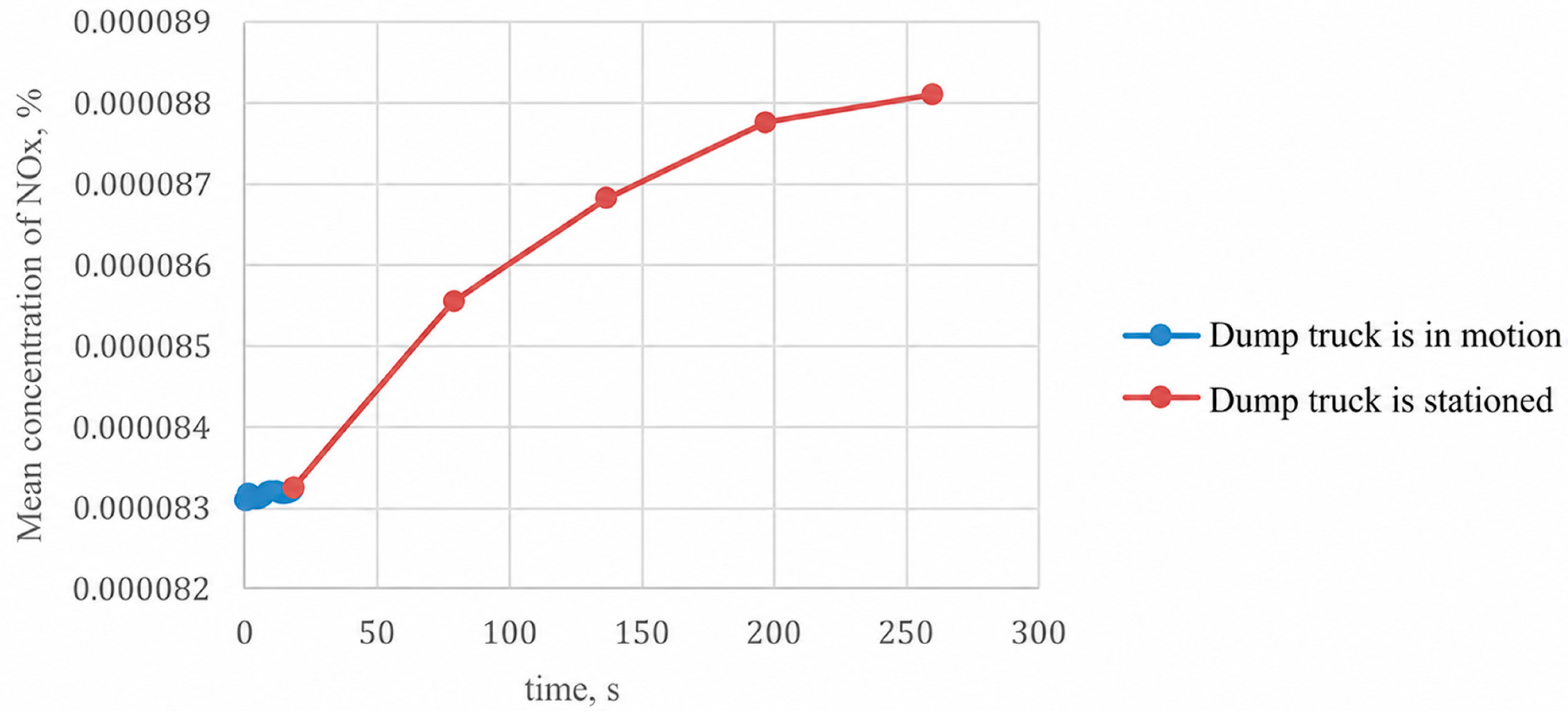
A longer time interval (4 min) is considered, which includes the dump truck entry (≈20 s), modeled with moving equipment, followed by a period of stationary operation with the engine idling next to the loader, modeled with fixed equipment. The evolution of the mean NOx concentration during dump truck motion into the chamber is shown in Figure 11.
Figure 11.
Evolution of mean NOx concentration in the chamber with mining equipment.
Contaminant accumulation occurs over several minutes: by the end of the fourth minute of simulation, the mean concentration has not yet fully reached the strictly steady-state value, but it has approached it closely. The initial value corresponds to the steady-state case with the dump truck stationary at the chamber entrance, whereas in the long-time limit the solution (red curve) tends toward the steady-state case with the dump truck at the chamber face, for which the mean NOx concentration is 0.000091%.
Figure 11 clearly shows that the contaminant buildup process is relatively slow and becomes significantly more pronounced only after the dump truck arrives and stops next to the loader, that is, when the piston effect due to its motion ceases. This time scale is generally comparable to the typical residence time of the dump truck in the chamber during loading. As a result, the total amount of gas in the blind-end chamber (indirectly characterized by the volume-averaged concentration) may not reach its maximum value within a single loading cycle. Consequently, it is reasonable to estimate the required airflow rate in the chamber without relying on an extremely conservative and practically unattainable scenario in which all equipment remains near the face for an indefinitely long time. The use of CFD modeling in combination with the dynamic mesh approach makes it possible to analyze a situation that is much closer to real operating conditions. This, in turn, offers the potential to reduce excessive safety margins in the design airflow required for ventilating such chambers. At the same time, these conclusions require further confirmation, primarily through experimental studies.
4. Conclusions and Future Work
Numerical simulation of unsteady heat and mass transfer processes in a large cross-section (132 m2) blind-end chamber of a gypsum mine with operating diesel equipment, performed using a dynamic mesh approach, allows the following conclusions to be drawn:
- The motion of the dump truck entering and leaving the chamber induces substantial disturbances in the airflow, temporarily altering the air volume flow rate in the chamber cross-sections and intensifying turbulent mixing. The highest airflow toward the face is observed when the vehicle is located at the chamber entrance, due to deflection and redirection of the fresh air jet into the chamber.
- The steady-state approach to assessing gas conditions in the blind-end chamber is sensitive to how the locations of mining equipment are prescribed and does not provide an adequate estimate of gas pollution in the near-face zone. It fails to account for the piston effect of the moving vehicle, the dynamics of interaction between the exhaust plume and the driver’s cab, and the process of gas accumulation after the vehicle has entered the chamber.
- It is shown that a steady-state simulation for the case where all mining equipment is located at the chamber face overestimates the total amount of contaminants in the chamber volume and may yield values that are not actually reached in operation if the duration of a loading cycle is shorter than the characteristic gas accumulation time in a large chamber. This effect is associated with the high inertia of contaminant buildup processes in such large cross-sectional volumes.
The present conclusions are based on numerical simulations of airflow, temperature, and contaminant transport parameterized using in situ measurements from the gypsum mine. Although the predicted trends are physically consistent and engineeringly plausible, independent validation of the flow and contaminant distributions in large blind-end chambers remains an important subject for future research.
Future work will focus on dedicated field measurements to validate and refine the numerical model. Particular attention will be paid to improving the specification of pollutant emissions from diesel-powered machinery, as this strongly influences contaminant concentrations within the working area. In addition, simulation results obtained with different turbulence models will be compared with field measurements to identify the most suitable turbulence model and calibration parameters.
Once validated, the model will be used to investigate a broader range of ventilation configurations, including alternative fan locations, the application of forcing or exhaust ventilation ducts, and modifications to the chamber geometry. Another promising direction is the development of microzoning ventilation strategies, in which ventilation is concentrated only in zones occupied by personnel or operating equipment rather than throughout the entire chamber volume. Such an approach is particularly attractive for large underground chambers, where full-volume ventilation may be inefficient.
Author Contributions
Conceptualization, L.L. and O.P.; methodology, L.L., O.P. and M.S.; investigation, S.M.; numerical modeling and formal analysis, I.P. and M.B.; visualization, S.B. and I.L.; writing—original draft preparation, M.S.; writing—review and editing, S.M., S.B. and I.L.; supervision, L.L. and O.P.; project administration, L.L. All authors have read and agreed to the published version of the manuscript.
Funding
This research was carried out with the support of the Russian Science Foundation under Project No. 26-97-20006.
Data Availability Statement
The data presented in this study are available from the corresponding author upon reasonable request.
Conflicts of Interest
The authors declare no conflict of interest.
References
- Gendler, S.G.; Seregin, A.S.; Belekhov, P.A. Study of the effects of operational and design characteristics of diesel equipment on gas contamination in underground mine workings. Russ. Min. Ind. 2025, 2025, 170–177. (In Russian) [Google Scholar]
- Kobylkin, S.S.; Kaledina, N.O.; Kobylkin, A.S.; Senatorov, V.A. Diesel exhaust gas dynamics in underground mines. Gorn. Zhurnal 2023, 2023, 94–102. (In Russian) [Google Scholar] [CrossRef] [Scilit]
- Duan, J.; Zhou, X.; Wang, H. CFD numerical simulation on diffusion and distribution of diesel exhaust particulates in coal mine heading face. Adv. Powder Technol. 2021, 32, 2891–2903. [Google Scholar] [CrossRef] [Scilit]
- Zhou, H.; Zhang, X.; Zhang, S. Sensitivity analysis of heat and mass transfer at working face in high-temperature mine. PLoS ONE 2024, 19, e0306269. [Google Scholar] [CrossRef] [Scilit] [PubMed]
- Xu, G.; Luxbacher, K.D.; Ragab, S.; Xu, J.; Ding, X. Computational fluid dynamics applied to mining engineering: A review. Int. J. Min. Reclam. Environ. 2017, 31, 251–275. [Google Scholar] [CrossRef] [Scilit]
- Yi, H.; Kim, M.; Lee, D.; Park, J. Applications of computational fluid dynamics for mine ventilation in mineral development. Energies 2022, 15, 8405. [Google Scholar] [CrossRef] [Scilit]
- Zheng, Y. Diesel Particulate Matter Dispersion Analysis in Underground Metal/Nonmetal Mines Using Computational Fluid Dynamics. Ph.D. Dissertation, Missouri S&T, Rolla, MO, USA, 2011. [Google Scholar]
- Zheng, Y.; Li, Y.; Thiruvengadam, M.; Lan, H.; Tien, J.C. DPM dispersion inside a single straight entry using dynamic mesh model. Int. J. Min. Sci. Technol. 2017, 27, 783–789. [Google Scholar]
- Levin, L.; Semin, M.; Maltsev, S.; Luzin, R.; Sukhanov, A. Numerical Analysis of the Impact of Variable Borer Miner Operating Modes on the Microclimate in Potash Mine Working Areas. Computation 2025, 13, 85. [Google Scholar] [CrossRef] [Scilit]
- He, X.; Li, Y.; Zhang, X. Influence of piston effect caused by cage operation on airflow field in transportation lane. J. Loss Prev. Process Ind. 2023, 82, 105012. [Google Scholar]
- Semin, M.A.; Maltsev, S.V.; Kolesov, E.V. Study of the influence of aerodynamic processes in a mine shaft with cable reinforcement on vibrations of a moving skip. Perm. J. Pet. Min. Eng. 2022, 22, 192–200. [Google Scholar]
- Wu, R.; Zhu, Z.; Cao, G. Computational fluid dynamics modeling of rope-guided conveyances in two typical kinds of shaft layouts. PLoS ONE 2015, 10, e0118268. [Google Scholar] [CrossRef] [Scilit] [PubMed]
- Saleem, H.A. Energy consumption reduction in underground mine ventilation system: An integrated approach using mathematical and machine learning models toward sustainable mining. Sustainability 2025, 17, 1038. [Google Scholar] [CrossRef] [Scilit]
- Yang, X.; Li, H. Digital twin-driven deep learning prediction and adaptive control for coal mine ventilation systems. Sci. Rep. 2025, 16, 940. [Google Scholar] [CrossRef] [Scilit] [PubMed]
- Clausen, E. Mine Ventilation in the 21st Century-Development Towards Adaptive Ventilation Systems. Min. Rep. 2017, 153, 8. [Google Scholar]
- Fedorov, D.A. Study of the Influence of Frontal Aerodynamic Resistance on Air Distribution in a Mine Ventilation Network. Ph.D. Thesis, MISIS, Moscow, Russia, 2026; 137p. (In Russian) [Google Scholar]
- Kobylkin, S.S.; Fedorov, D.A.; Kuznetsov, I.I. New classification of mine ventilation resistance. Russ. Min. Ind. 2025, 2025, 92–96. (In Russian) [Google Scholar]
- Addis, J.; Gangrade, V.; Harris, M.; Mohamed, K.; Raj, K.V.; Sarkar, S. Enhancing Ventilation and Development Planning in Underground Stone Mines: Insights from a CFD-Based Study; CDC Stacks: Cdc:215673; NIOSH: Cincinnati, OH, USA, 2024. [Google Scholar]
- de Vilhena Costa, L.; da Silva, J.M. Analysis of heat sources: Alternatives for improving environmental conditions in an underground gold mine. Res. Soc. Dev. 2023, 12, e0812239651. [Google Scholar] [CrossRef] [Scilit]

Disclaimer/Publisher’s Note: The statements, opinions and data contained in all publications are solely those of the individual author(s) and contributor(s) and not of MDPI and/or the editor(s). MDPI and/or the editor(s) disclaim responsibility for any injury to people or property resulting from any ideas, methods, instructions or products referred to in the content. |
© 2026 by the authors. Licensee MDPI, Basel, Switzerland. This article is an open access article distributed under the terms and conditions of the Creative Commons Attribution (CC BY) license.