


Abstract
This article examines the performance of negative-sequence overcurrent protection during short circuits in the presence of current asymmetry caused by single-phase loads, such as those encountered in AC railway traction systems. The impact of unbalanced loads on the generation of negative-sequence currents is analyzed using field test data and a mathematical model. Various operating modes of an electric power network under unbalanced loading conditions are simulated in MATLAB Simulink R2015a. It is shown that under significant load asymmetry, negative-sequence currents can reach magnitudes comparable to those of short-circuit currents, thereby increasing the risk of false protection operation. To address this issue, a modified negative-sequence overcurrent protection scheme is proposed that ensures both sensitivity and selectivity. The modification is based on analyzing the ratio of negative-sequence to positive-sequence current phasors and monitoring the rate of change of the negative-sequence current. A faulted phase selector is also incorporated into the protection scheme. Simulation results confirm the effectiveness of the modified protection in reliably identifying unsymmetrical short circuits under varying unbalanced load conditions, including remote faults with high fault resistance.
1. Introduction
The digitalization of the electric power industry is gradually leading to the replacement of analog relay protection (RP) complexes with microprocessor-based devices. Although this transition has not resulted in fundamentally new types of protection, the implementation of individual RP functions in digital form has become less resource-intensive. A prominent example is RP based on symmetrical component filters (SCFs), in particular, negative-sequence overcurrent protection (NSOCP), which is highly sensitive to unbalanced short circuits (SCs) [1,2,3,4].
Despite the apparent maturity of NSOCP theory, its practical application reveals significant vulnerabilities, particularly in networks with non-traditional load profiles. The widespread integration of heavy single-phase AC traction loads, such as those in AC railway systems, generates sustained negative-sequence (NS) currents in normal operating modes that can reach magnitudes comparable to SC currents [5,6,7]. This fundamentally challenges the traditional design assumptions of NSOCP.
This paper focuses on this critical vulnerability: the performance of NSOCP under conditions of stochastic, high-magnitude load asymmetry. While existing literature extensively covers NSOCP in symmetrical systems or addresses modern challenges like inverter-based resources, the specific problem of protection selectivity under heavy traction load asymmetry remains insufficiently explored. The main contribution of this work is the development of a modified NSOCP scheme based on the logical interlocking of three criteria: the complex ratio of NS to PS current phasors, the rate of change of the NS current, and a built-in faulted phase selector (FPS). While these concepts exist separately in prior literature, their integration creates a non-linear logical barrier that overcomes the physical limitations of each individual method when applied to heavy traction load asymmetry.
The remainder of this paper is organized as follows: Section 2 reviews the literature and identifies the research gaps. Section 3 analyzes NS currents caused by unbalanced traction loads using field data. Section 4 and Section 5 present the simulation models for unbalanced load and short-circuit modes, respectively. Section 6 details the proposed NSOCP algorithm. Section 7 evaluates its performance, and Section 8 concludes the paper.
2. Literature Review
2.1. Analysis of Negative-Sequence Overcurrent Protection Application Approaches in Symmetrical Systems
Most research on the application of NSOCP is devoted to networks with symmetrical loads or systems dominated by three-phase consumers. In [8,9,10], the feasibility of using NSOCP as backup or primary protection for 110 kV and higher transmission lines is substantiated. The authors highlight its advantages over zero-sequence overcurrent protection (ZSOCP), such as eliminating the need to account for mutual induction between parallel lines and providing a more stable equivalent circuit for SC current calculations. Specifically, reference [8] demonstrates that NS components can significantly enhance the sensitivity of distance protection during unbalanced SCs, while refs. [9,10] detail the improvements in directional protection and selectivity in complex network configurations with bidirectional power flow.
Furthermore, NSOCP is being increasingly proposed as a sensitive element in multi-parameter and adaptive protection systems [11], as well as for faulted phase selection algorithms that operate reliably even under high fault resistance [12].
However, a critical analysis of these foundational and modern studies reveals a common underlying assumption: the NS current in the normal operating state is considered negligible (typically not exceeding 5–10% of the rated current). While this assumption holds true for networks with symmetrical loads, it becomes fundamentally invalid in the presence of high-power single-phase consumers. This creates a critical gap in protection selectivity that this study addresses.
2.2. Current Research on the Problem of Unbalanced Loads in Networks with Traction Power Supply
In recent years, the integration of non-traditional loads and distributed generation has introduced new challenges for RP. While significant attention has been given to the impact of inverter-based resources on NSOCP performance [13,14,15,16], the specific issues arising from high-power single-phase traction loads require dedicated investigation.
For traction power supply systems, reference [17] examines the impact of asymmetric traction loads on RP operation, substantiating that NS currents caused by traction can exceed those arising during out-of-step conditions. Similarly, the study in [18] demonstrates that NSOCP offers the widest operating range for phase-to-phase faults compared to traditional elements, particularly in scenarios where fault currents are lower than load currents.
Despite these findings, the stochastic nature of electric rolling stock, combined with the specific asymmetry introduced by traction power supply systems, necessitates a more focused analysis of protection selectivity under these conditions.
2.3. The Problem of Negative-Sequence Overcurrent Protection Selectivity Under Asymmetric Loads
In [19,20,21], it is noted that NS currents from single-phase electric rolling stock can reach values comparable to SC currents on the external power supply side of traction substations. This creates a risk of maloperation of NSOCP on lines feeding traction substations, as well as on adjacent network elements.
The study in [22] considers the application of energy storage systems for regulating the maximum demand of traction substations. It is shown that the use of an energy storage system can effectively reduce NS currents generated by traction load. The research proposes a method for active maximum demand regulation based on short-term forecasting, which can be used to reduce the level of asymmetry in normal operating conditions.
The main contradiction identified in the literature is as follows: on the one hand, NSOCP theoretically possesses high sensitivity to unbalanced SCs; on the other hand, this same sensitivity makes the protection vulnerable to sustained asymmetric loads. Moreover, there are no standardized methods for coordinating NSOCP against load asymmetry, and existing recommendations are limited either to coarse setting adjustments (which reduces sensitivity) or to the use of additional blocking elements, whose parameters require thorough justification.
2.4. Critical Assessment of Proposed Methods for Improving Selectivity
Various authors have proposed algorithms for distinguishing SCs against the background of asymmetric loads. In [23], a method based on analyzing the ratio of NS to positive-sequence (PS) currents is proposed. In [24], the rate of change of NS currents is used to differentiate smooth variations caused by locomotive movement from a sharp increase during a SC. In [25], a combined protection scheme with an FPS based on comparison of phase current increments is considered.
However, a critical analysis of these works reveals a number of systematic shortcomings:
- Lack of a comprehensive approach. Most studies only consider one criterion (the unbalance ratio or the rate of change) without integrating them into a single algorithm adapted to actual operating conditions.
- Insufficient validation on real-world data. The proposed methods are often tested on idealized models that do not account for the stochastic nature of traction loads, transient processes during locomotive switching, or the asymmetry introduced by traction power supply systems.
- Neglect of higher harmonic effects. Traction loads generate significant harmonic distortions that can affect the performance of digital SCFs. Issues related to the noise immunity of NSOCP under actual harmonic pollution conditions are virtually unaddressed.
2.5. Justification for the Need to Modify Negative-Sequence Overcurrent Protection
Based on the critical analysis, the following key gaps can be identified that have not been adequately addressed in existing studies:
- The absence of a methodology that combines, in a single algorithm, the analysis of the ratio of NS to PS currents with monitoring of the rate of change of the NS current;
- Insufficient development of FPS algorithms capable of unambiguously identifying the faulted phase during unbalanced SCs against the background of non-stationary load asymmetry;
- Unresolved issues of coordination against external unbalanced SCs and ensuring selectivity under high transient current components;
- Lack of experimental validation of the proposed algorithms for remote faults with high fault resistance, which is particularly important for networks with traction loads.
Thus, existing approaches to the design of NSOCP cannot be directly applied in networks with variable load asymmetry without substantial modification. This justifies the need to develop a modified protection scheme that combines criteria ensuring reliable detection of unbalanced SCs with an FPS algorithm adapted to traction load conditions.
This study analyzes unbalanced load currents and develops measures to ensure correct operation of NSOCP during SCs under conditions of current asymmetry caused by traction load.
3. Analysis of Negative-Sequence Currents Caused by Unbalanced Load from Traction Substations
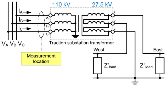
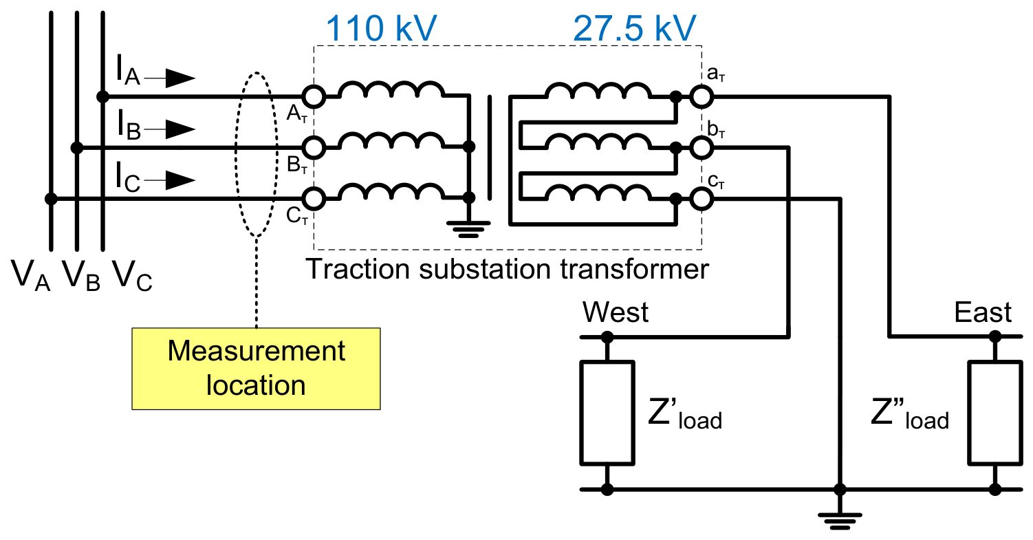
The traction load of AC railways operating at 27.5 kV consists of single-phase power receivers—specifically, electric locomotives—connected to one of the phase-to-phase voltages (Figure 1). Variations in power consumption during locomotive movement and the transition of locomotives from one substation to another cause the electrical loads on the substations to change over time.
Figure 1.
Electrical diagram of a traction substation indicating the measurement location.
A distinctive feature of the performed power quality measurements is that they only provided information on the RMS values of phase and line voltages, without information on their phase angles. When a three-phase four-wire connection scheme is used for the measurement device, the voltage is taken as the reference voltage with an initial phase of zero. To determine the initial phases of the vectors and with respect to , formulas (1) and (2) were applied, which are based on the law of cosines and utilize only the magnitudes of the phase voltages , , and and line voltages and :
It is important to emphasize that the application of the law of cosines in this context provides an exact geometric solution for the phase angles, rather than an approximation. In a three-phase system, the magnitudes of phase and line-to-line voltages strictly determine the angular relationships within the voltage triangle, ensuring that the reconstructed phasors are mathematically rigorous and free from the discrepancies typically associated with heuristic estimation methods.
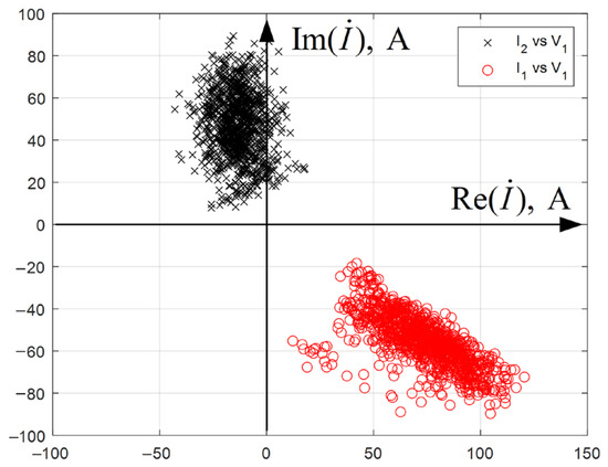
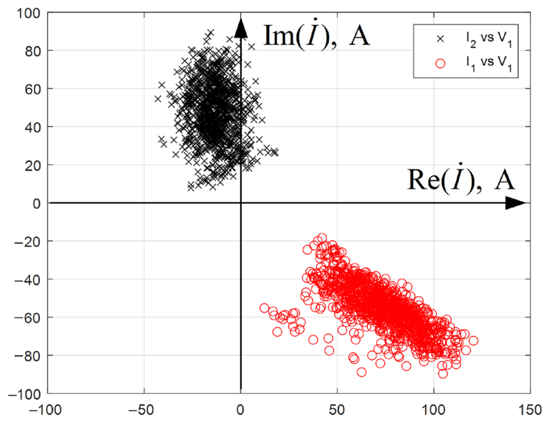
The obtained phase voltage and current vectors—the angles of the currents relative to the phase voltage vectors are recorded by the measurement device—enabled the application of the method of symmetrical components and the calculation of PS and NS current vectors. An example of processing measurements taken during the day on the 110 kV side of a step-down traction substation transformer is shown in Figure 2.
Figure 2.
Result of decomposition into symmetrical components of the load current on the 110 kV side of a traction substation, displayed on the complex plane: positive-sequence and negative-sequence currents, plotted relative to positive-sequence voltage.
It can be seen that the NS currents—plotted by default relative to the NS voltage, as is customary in directional RP—do not have a predominant location area; they occupy all four quadrants. At the same time, the PS currents, plotted in Figure 2 relative to the PS voltage, form a compact region of points in the fourth quadrant.
For subsequent analysis, it is necessary to reference both current phasors to the same reference vector, for which the PS voltage is proposed. This is an important distinction from directional RP, where the symmetrical voltage component of the same sequence is used as the reference vector. The correction of the NS current vectors was performed using the following formula:
The resulting plots of the corrected PS and NS current vectors are shown in Figure 2. It can be seen that the PS and NS currents obtained from (3) lie in different quadrants, and their regions do not overlap.
4. Simulation of Unbalanced Load Modes
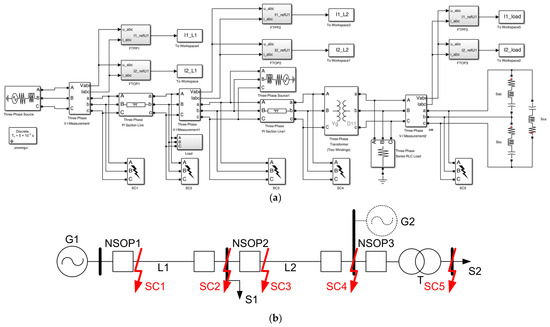
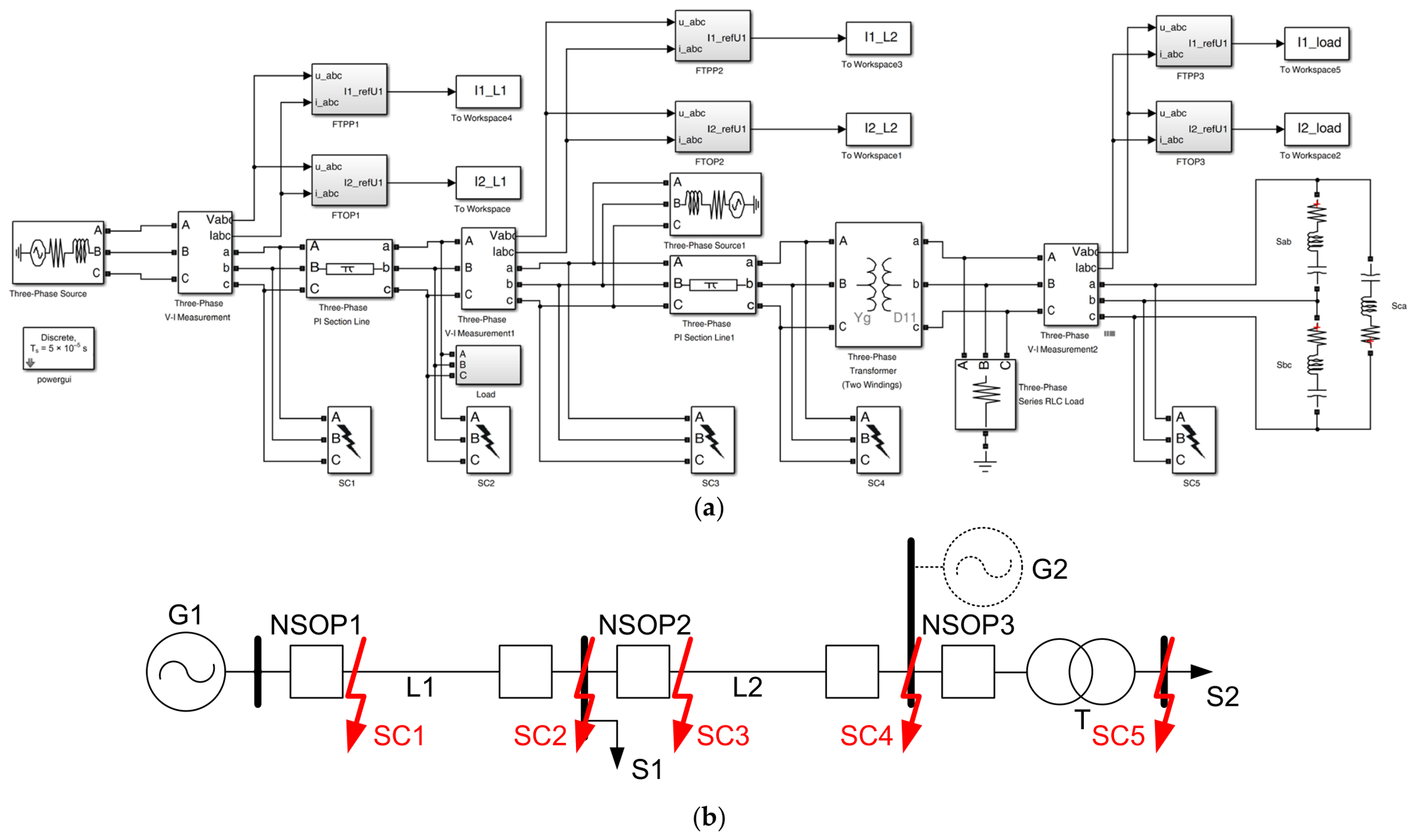
For an extended analysis of NS currents under unbalanced load conditions, a simulation model of a traction substation and the external electrical network was developed in the MATLAB Simulink environment (Figure 3a). The network design diagram (Figure 3b) comprises a generalized 110 kV electrical system G1, a 110 kV power line L1 of 30 km length terminated with an unbalanced load S1, and a 110 kV power line L2 of 60 km length feeding a three-phase 110/27.5 kV traction substation transformer T rated at 25 MVA. A randomly varying unbalanced load S2 is connected on the 27.5 kV side. NSOCP is provided at the beginning of each power line and at the transformer. The model also allows connecting system G2 to analyze protection operation during reverse faults. Five fault points (SC1–SC5) are included to simulate various damage types. To implement NSOCP, SCFs with the necessary PS voltage reference vectors are assembled.
Figure 3.
Simulation model in MATLAB Simulink (a) developed for a 110 kV electrical network with unbalanced load (b).
The random temporal variation of loads S1 and S2 was modeled using the Monte Carlo method to obtain different values of PS and NS currents. For each iteration, a steady-state operating point was simulated with random phase loads ranging from 0 to 5 MW at a power factor of 0.8. The power distribution over this interval was assumed to be uniform to generate diverse combinations of phase powers. The maximum power of 5 MW was chosen based on the actual power of electric locomotives observed during field tests. A uniform distribution was intentionally selected for the Monte Carlo simulations as a conservative bounding approach. By testing the protection algorithm across the entire possible operating space (0 to 5 MW) without assuming a specific probabilistic peak, we ensure that the derived load regions remain valid and robust under any realistic, non-uniform railway operating conditions.
To ensure the reproducibility of the results, the Monte Carlo simulation was configured with specific parameters. The simulation performed 10,000 steady-state iterations. In each iteration, the active power of the unbalanced loads S1 and S2 was randomly generated using a uniform distribution between 0 and 5 MW, with a fixed power factor of 0.8 lagging. The phase connection of the single-phase loads was also randomized across the available phase-to-phase combinations (e.g., AB, BC, CA) to cover all possible asymmetry scenarios. For each iteration, the steady-state PS and NS current phasors were recorded at the NSOCP location. This steady-state phasor sweep approach, rather than a full electromagnetic transient simulation, was intentionally chosen to isolate and rigorously test the fundamental selectivity boundaries of the proposed phase-based protection algorithm against the entire spectrum of possible load asymmetry conditions, independent of site-specific transient noise.
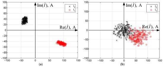
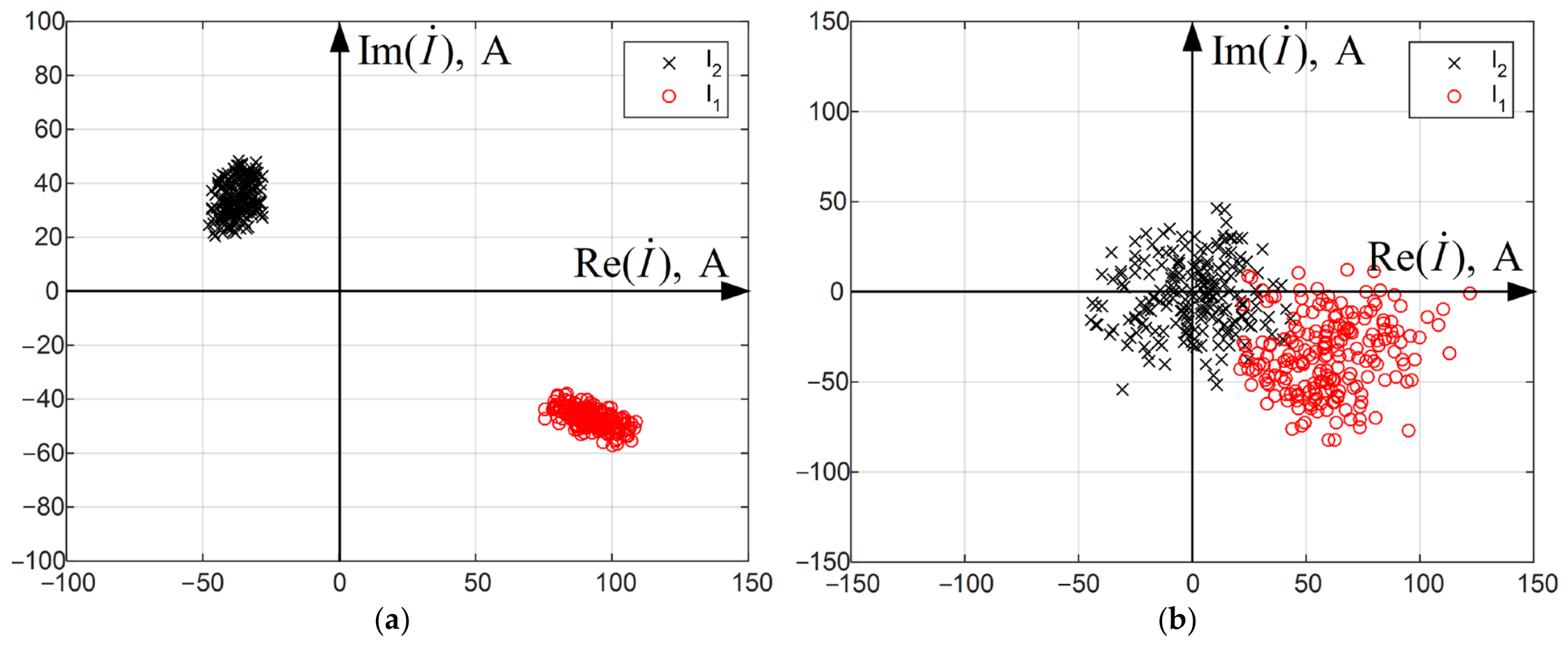
First, the case where the load is connected to only two of the three transformer phases (as in the scheme shown in Figure 1) was considered. The regions of PS and NS current points obtained from the Monte Carlo tests, plotted relative to the PS voltage on the HV side of the substation transformer, are shown in Figure 4a. A distinctive feature of the validation approach is that the comparison between field measurements and simulation results is performed in the complex plane of symmetrical component phasors, rather than in the time domain. Due to the stochastic nature of traction loads and the lack of precise operational data regarding the exact number and power of electric locomotives during the field measurements, an exact quantitative match of current amplitudes is physically impossible. More importantly, an exact amplitude match is irrelevant to the validation of the proposed protection algorithm, which operates based on the phase relationships (angular positions) of the current phasors. Therefore, the quantitative validation metric for this study is the coincidence of the quadrant locations of the PS and NS current phasors relative to the PS voltage. The exact match of these complex-plane regions with Figure 2 confirms that the model correctly reproduces the angular distribution of asymmetry, which is the exact parameter required to validate the phase-based protection logic, ensuring that no important discrepancies are concealed.
Figure 4.
Regions of positive-sequence currents (marked as O) and negative-sequence currents (marked as X) on the complex plane when simulating an unbalanced load on two phase-to-phase voltages (a) and on three phase-to-phase voltages (b).
Simulation was also performed for the case where an unbalanced random load is connected across all three phases. The resulting regions of PS and NS currents in this mode are shown in Figure 4b. It can be seen that under a three-phase unbalanced load, PS and NS currents may appear in all four quadrants, which will complicate the direct identification of fault currents against the background of load currents.
Admittedly, validation by quadrant coincidence is an oversimplification. However, comparing time-domain waveforms or exact current amplitudes is infeasible due to the stochastic nature of traction loads and the absence of precise operational data on the number and power of electric locomotives during field measurements. To provide a quantitative metric beyond visual quadrant coincidence, a statistical comparison of the normalized complex ratio was performed between field measurements and Monte Carlo simulation. Normalizing the NS current to the PS current inherently eliminates the amplitude mismatch caused by unknown train compositions. Table 1 presents the statistical parameters for both datasets. The mean magnitudes differ by less than 9%, and both phasors reside in the same quadrant. The angular difference is physically explained by the uniform distribution of phase connections and constant power factor assumed in the simulation, contrasting with real-world operational constraints. Notably, the standard deviation of the experimental data (0.033) is smaller than that of the simulation (0.096), confirming that the real-world load occupies a constrained subset of the conservative bounding space mapped by Monte Carlo.
Table 1.
Statistical comparison of the normalized complex ratio under unbalanced load conditions.
5. Simulation of Unsymmetrical Short Circuits
Using the same MATLAB Simulink simulation model (Figure 3a), NS and PS currents were obtained for unsymmetrical SCs occurring in various sections of the electrical network under pre-fault load asymmetry. The simulated fault locations included the beginning and end of both power lines, as well as the secondary side of the traction substation transformer (Figure 5). The following fault types were considered: single-phase-to-ground and double-phase-to-ground faults within the 110 kV network (points SC1–SC4), and phase-to-phase faults at all fault points (SC1–SC5). Three-phase faults are not addressed in this paper, as they do not produce sustained current asymmetry and are cleared by protection functions based on a different operating principle (e.g., distance protection).
Figure 5.
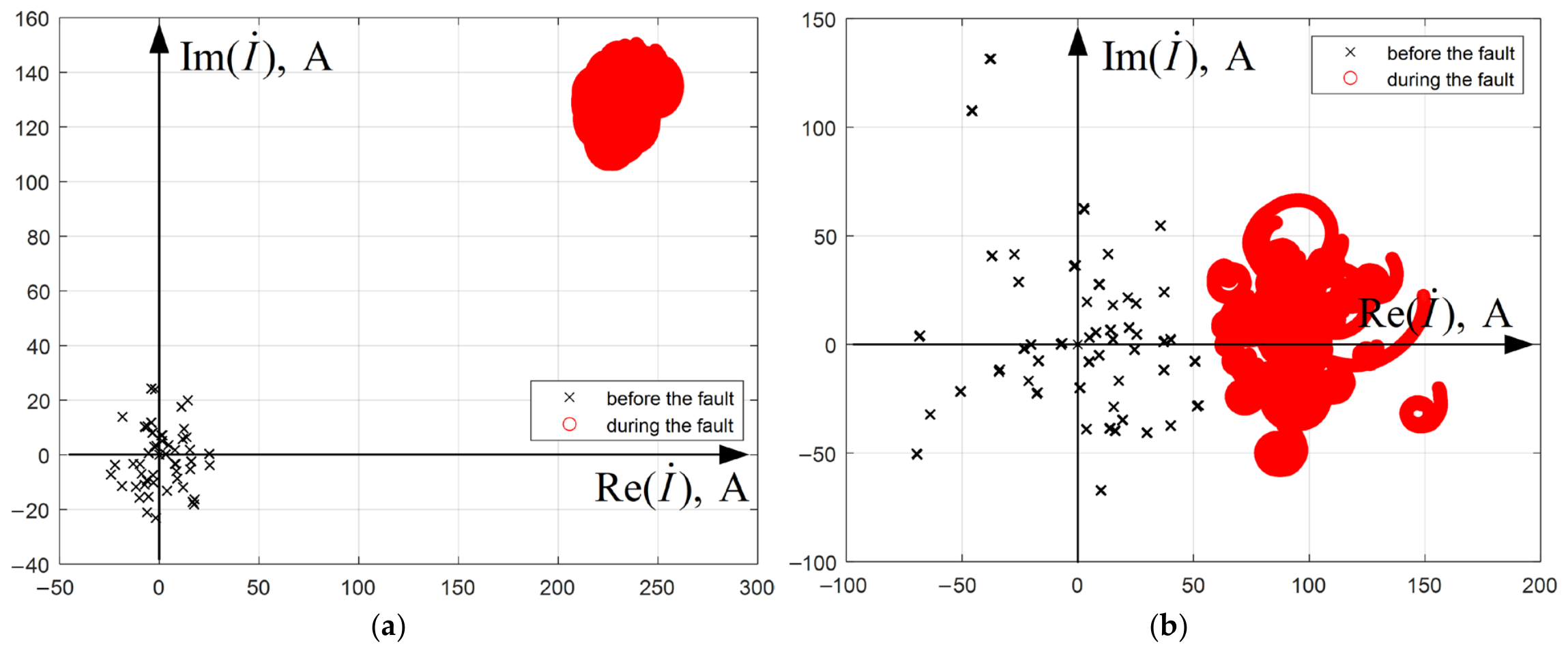
Example of plotting negative-sequence current regions in load mode (marked as X) and during short circuits (marked as O) on the complex plane when simulating a solid phase-to-phase fault with minimal load asymmetry (a) and when simulating a phase-to-phase fault through a transition resistance of 10 Ohm under conditions of significant load asymmetry (b).
It was found that during unsymmetrical SCs, the region of the NS current on the plane, formed according to the previously stated rules, can also be located in different quadrants depending on the fault type and combination of damaged phases, as is the case with unbalanced load. However, the NS current during a fault differs significantly from the load NS current in amplitude (e.g., Figure 5a). While bolted SC currents are typically significantly higher than load currents, in networks with moderate SC levels or during remote faults with high transition resistance, the fault-induced NS current can drop to magnitudes comparable to those generated by heavy single-phase traction loads. For instance, a 5 MW traction load can reflect 1.0–1.5 kA of NS current to the 110 kV side, which may overlap with the current of a high-resistance remote fault. However, with great fault remoteness and significant fault resistance, the NS current during a fault becomes practically indistinguishable from the NS current caused by load asymmetry (Figure 5b). Thus, implementing a sensitive and selective NSOCP with a setting based solely on current magnitude becomes impossible under conditions of significant load asymmetry and fault remoteness. This specific boundary condition is the primary challenge that the proposed modified NSOCP is designed to resolve.
For example, in the simulation of a phase-to-phase fault with a 10 Ohm transition resistance (Figure 5b), the absolute magnitude of the NS current drops significantly, becoming nearly indistinguishable from that caused by load asymmetry. However, the complex ratio remains anchored to its characteristic fault region, demonstrating the method’s robustness in detecting high-impedance faults where traditional magnitude-based NSOCP would fail.
6. Modified Negative-Sequence Overcurrent Protection Ensures Sensitivity and Selectivity Under Load Asymmetry Conditions
While the representation of symmetrical components on a complex plane is an established concept in RP, the genuine novelty of the proposed method lies in the specific combination of two criteria: the use of the complex ratio to form distinct, load-independent fault clusters, and the integration of a rate-of-change () criterion. This dual-criteria approach dynamically discriminates between actual faults and sudden load pickups that might momentarily enter the fault clusters, addressing a critical gap in existing single-criterion methods.
To identify SCs against the background of unbalanced load conditions, the ratio of the NS and PS current vectors (4) is proposed as the operating quantity, denoted as a complex coefficient :
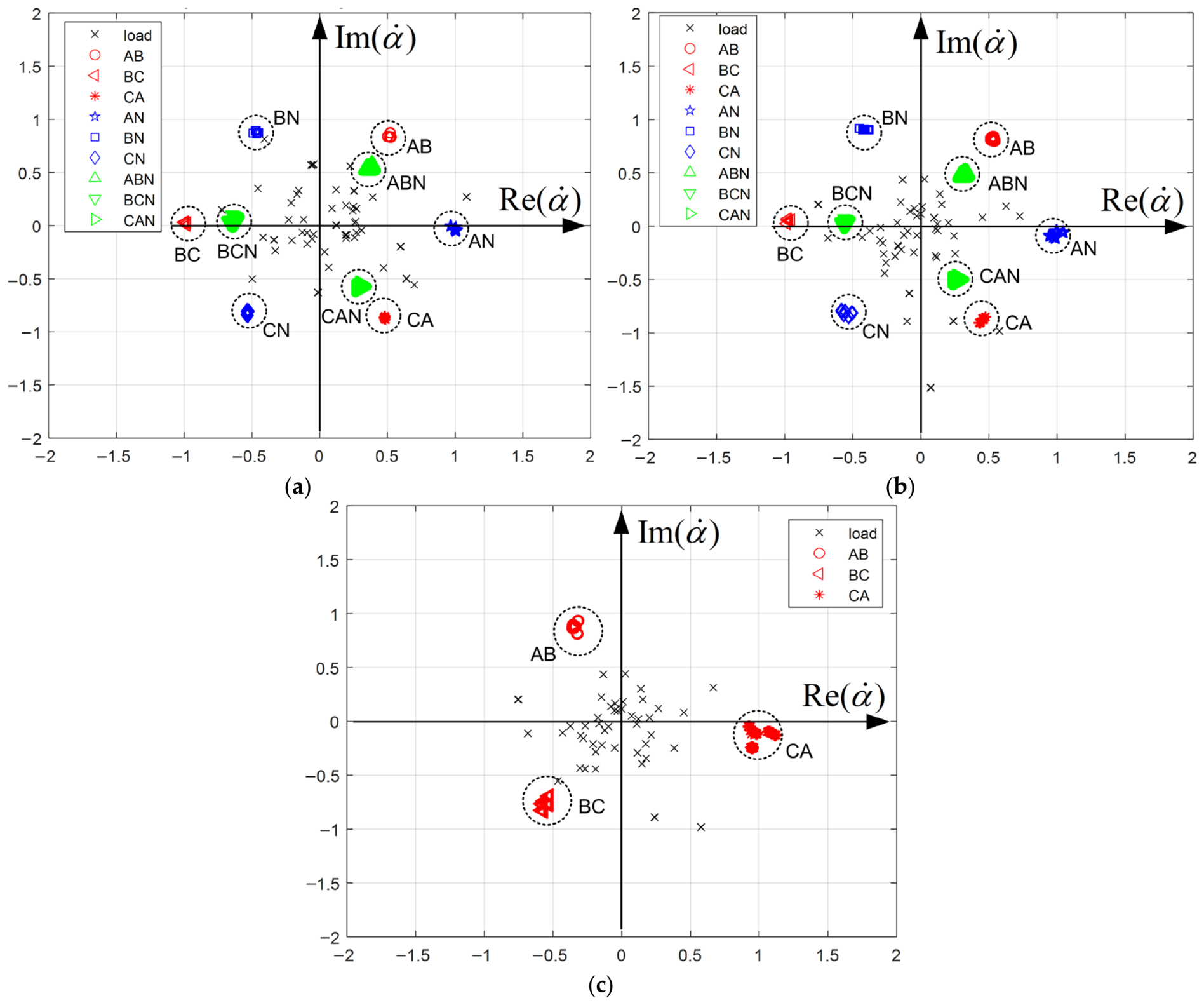
It is necessary to investigate the behavior of this coefficient on the complex plane under both load conditions and SCs at various points in the network shown in Figure 3. Figure 6 presents a summary of the computational experiments. As an example, the values of the coefficient measured by the protection NSOCP2 installed at the beginning of power line L2 (Figure 3a) are shown for all types of unsymmetrical faults at the beginning of line L2 (point SC3), at the end of L2 (point SC4), and behind the traction substation transformer T (point SC5). Simulation of a reverse fault (point SC2) with system C2 connected was also performed. The regions of the most probable location of the coefficient for all unsymmetrical faults are obtained and indicated by dashed circles in Figure 6.
Figure 6.
Regions of coefficients on the complex plane in load mode (marked as X) and during unsymmetrical faults at point SC3 (a), point SC4 (b), and point SC5 (c), measured by protection NSOCP2 in Figure 3b.
Simulation of the pre-fault mode shows that the coefficient can fall into the operating regions (indicated by the dashed circles) even in the absence of a fault. Therefore, to distinguish between unbalanced load conditions and unsymmetrical faults, monitoring the rate of change of the NS current per industrial frequency cycle can be considered. The complex plane defines the static fault signature, but the rate of change of the NS current serves as the main dynamic blocking mechanism. This temporal evolution criterion is the key innovation that prevents maloperation during sudden load pickups, which might momentarily enter the static fault clusters on the complex plane. The setting for the rate of change of the NS current should be detuned from the maximum possible rate caused by energization of an unbalanced load on the given feeder. For example, for a single-phase load connected to a single phase-to-phase voltage (for definiteness, phase-to-phase AB) and consuming a current , the maximum increment of NS current upon its connection will be:
where is the rotation operator. By detuning the coarse stages of the NSOCP from the setting in (5), neither the sudden connection of an unbalanced load nor its subsequent variations during operation will cause the modified NSOCP to trip. Thus, the settings for this element can be determined analogously to the starting elements based on the NS current increment used in phase comparison protection of power lines.
Comparison of Figure 6a,b shows that the regions of the coefficient for the same fault types are practically independent of the fault distance. This indicates the necessity of retaining a starting element based on the magnitude of the NS current in the NSOCP.
The difference in the operating regions shown in Figure 6c from those in the other two figures is explained by the fact that point K5 is located behind a transformer with a vector group of 11 (e.g., YNd11). This introduces a 60° phase shift (30° twice, due to the division of NS and PS currents with opposite sign shifts) compared to faults on the 110 kV side in Figure 6a,b.
Thus, for the proposed modified NSOCP to operate, the following conditions must be met:
- The NS current magnitude exceeds the setting of the corresponding NSOCP stage;
- The coefficient lies within one of the regions indicated by the dashed lines in Figure 6;
- The rate of increase of the NS current, memorized for a time sufficient for the NSOCP stage to operate, is above a setting reliably detuned from the maximum NS current change during unbalanced load pickup;
- The NS directional power element is operating (if directional NSOCP is implemented).
It is worth noting that the use of the coefficient does not provide inherent directionality, as its phase angle is determined by fault type and network impedance ratios rather than power flow direction. Therefore, to ensure NSOCP selectivity in a network with two-way power supply, a conventional NS directional power element remains a necessary component of the protection suite. The functional novelty of the proposed method lies not in replacing directional elements, but in ensuring reliable fault/load discrimination under heavy asymmetry where traditional magnitude-based criteria fail.
An additional advantage of the modified NSOCP is the built-in FPS, implemented using the regions of the coefficient in Figure 6. ZSOCP, which measures the magnitude of the ZS current and its phase relative to the ZS voltage (when directional protection is used), does not have the capability to determine the faulted phase. Using the phase relationships between PS and NS currents allows an FPS to be embedded within the protection itself rather than relying on separate elements. Known FPS implementations utilize distance elements [25,26], elements based on the phase relationships of NS and ZS currents [26,27], and elements based on current and voltage magnitudes and their fault components [26,27,28,29], which significantly complicates the protection. An important distinction of the proposed NSOCP compared to these FPS options is that the FPS is not intended for implementing single-phase autoreclosing, but rather serves as a by-product of ensuring selectivity by determining the fault type.
It should be explicitly noted that this embedded FPS is primarily intended to enhance protection selectivity by identifying the fault type for the correct operating region selection, rather than to support Single-Phase Autoreclosing (SPAR) logic, which requires additional criteria such as secondary arc extinction monitoring.
7. Performance Evaluation of the Modified Negative-Sequence Overcurrent Protection
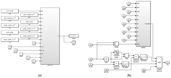
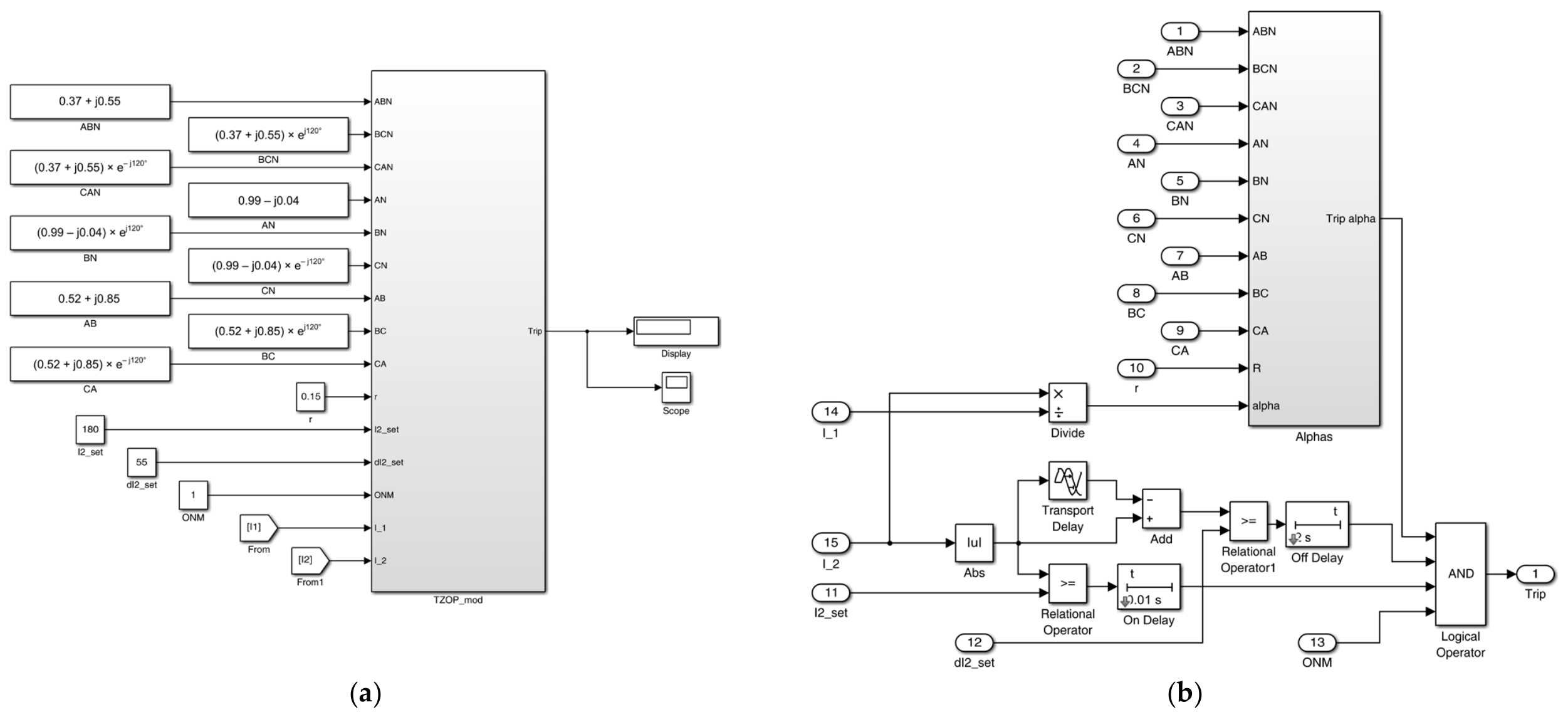
To evaluate the performance of the modified NSOCP with FPS under load asymmetry conditions, a model of the protection logic was developed in MATLAB Simulink. Figure 7a shows an overview of the NSOCP model implementing the described protection logic with the coefficient and the NS current increment element. Figure 7b shows the block diagram of the protection measuring elements. The equation that implements a circular operating characteristic [30,31] in the complex plane of the coefficient is as follows:
where is the coordinate of the center of the circular operating region for the considered steady-state fault type, determined from simulation as the mathematical expectation of the coefficient ; is the radius of the operating region, taken as 0.15 p.u.
Figure 7.
General view of the block diagram of the simulation model of the modified negative-sequence overcurrent protection in MATLAB Simulink (a) and its measuring elements for the negative-sequence current, its increment, and the coefficient (b).
The settings for each type of unsymmetrical fault, obtained from simulation, are given in Table 2 and can be configured as default (non-editable) protection settings.
Table 2.
coefficients, which correspond to the centers of operating regions for different types of unsymmetrical short circuits.
Strictly speaking, the coefficients obtained from simulation can also be determined analytically. These coefficients can be calculated using unsymmetrical faults with phase A taken as the reference. For instance, from [30], the relationships between PS and NS currents at the fault point for various unsymmetrical fault types are known and summarized in Table 3.
Table 3.
Analytical expressions for positive-sequence and negative-sequence currents during unsymmetrical faults with special phase A and corresponding calculated values of coefficients .
The radius of the circular operating region is set to 0.15 p.u. This value is analytically justified by standard microprocessor relay engineering margins. It provides a 15% tolerance to accommodate combined CT/VT measurement errors (typically 3–5%), relay calculation inaccuracies (up to 5%), transient DC offset effects, and minor variations in ZS impedance during double-phase-to-ground faults. Furthermore, deterministic phase shifts introduced by transformer vector groups (e.g., the 60° shift for YNd11 transformers) are predictable and can be compensated for in the relay settings, similar to phase compensation in conventional transformer differential protection elements, ensuring the portability of the method.
Changes in system parameters such as line length and source strength primarily affect the absolute magnitude of the fault current, but the ratio for a specific fault type remains relatively stable, as demonstrated by the analytical expressions in Table 3. The residual variance from these parameters is fully absorbed by the 0.15 p.u. safety margin, which is designed to cover standard measurement and calculation errors. Furthermore, the analytical assumption of equal PS and NS impedances () and identical source EMFs may fail in heterogeneous grids. In real networks, the actual centers of the operating regions are determined via simulation (Table 2) or field tuning. The discrepancies caused by the violation of the assumption and source EMF mismatches are mostly absorbed by the 0.15 p.u. radius of the circular operating characteristic.
It should also be noted that modern microprocessor relays calculate symmetrical components using a Full-Cycle Discrete Fourier Transform (DFT) filter. The DFT inherently rejects steady-state integer harmonics (e.g., 3rd, 5th, 7th) typical of traction loads. Therefore, the calculated fundamental frequency phasors remain stable, and any minor transient distortion falls well within the 0.15 p.u. safety margin of the proposed operating regions.
Since most power supply schemes for unbalanced loads are radial, the equivalent circuit for a network with two-way power supply can be reduced to a two-beam circuit, where one beam (denoted in Table 3 with a single prime) corresponds to the NSOCP location, and the other beam (denoted with double primes in Table 3) corresponds to the remaining branches feeding the fault point. Assuming that the electromotive forces in each of the two equivalent beams are identical and that the PS and NS impedances of each network element are approximately equal, the analytical values of the coefficients according to Table 3 can be found. The obtained values agree well with the simulation results shown in Figure 6 and Table 2. Adjustment of the operating region may only be needed for double-phase-to-ground faults, as the ratio between NS and PS currents for this fault type varies somewhat depending on the ZS impedance.
As a result of simulating various load and fault conditions, it was found that for all unsymmetrical SCs, the modified NSOCP operates and correctly identifies the combination of damaged phases under conditions of pre-fault asymmetry. At the same time, no false tripping of the modified NSOCP occurs during sudden connection of an unbalanced load or during sudden load pickups. The settings for the modified NSOCP are only the pickup current (as in traditional NSOCP) and the maximum possible NS current increment in normal mode, which can be calculated using formula (5).
Quantitative analysis of the simulation results indicates that the modified NSOCP maintains a sensitivity margin of at least 20% above the maximum expected load-induced increment while achieving fault detection times comparable to traditional instantaneous overcurrent stages (typically within 20–40 ms, depending on the specific relay processing cycle).
To provide a summary of the proposed method’s performance and to clearly demonstrate the necessity of each modification step, Table 4 compares the operational outcomes of three protection variants across critical scenarios. To demonstrate the robustness of the proposed method under the most challenging conditions, the SC scenarios correspond to fault point SC4, which is located at the end of the backup protection zone (at the end of the adjacent line). For each fault type, 50 simulations were performed, combining random pre-fault load asymmetry states and random fault inception angles. Additionally, 200 sudden load pickup scenarios were simulated. The results confirm that while conventional magnitude-based NSOCP suffers from massive maloperations under loading (1588 false trips) and sensitivity loss during high-resistance faults (71 missed faults), the introduction of complex-plane regions significantly reduces these errors (down to 35 false trips and 30 missed faults). However, it remains vulnerable to transient load pickups. The final integration of the rate-of-change criterion creates a robust logical barrier, ensuring 100% correct classification across all 10,400 simulated scenarios with zero errors.
Table 4.
Comparative performance of negative-sequence overcurrent protection variants across critical scenarios.
Additional protection, e.g., distance protection, would be needed to detect and clear symmetrical three-phase faults. For this reason, the modified NSOCP is better suited for protecting equipment in networks of 110 kV and above, as it replaces ZSOCP and partially performs the functions of distance protection for phase-to-phase faults. Consequently, the proposed NSOCP is not designed to operate as a standalone, universal protection function. In practical applications, it must be integrated into a comprehensive protection suite, where it replaces ZSOCP and provides sensitive backup for phase-to-phase faults, while symmetrical three-phase faults are cleared by conventional distance or phase overcurrent protection elements.
It is also worth noting that NSOCP, unlike ZSOCP, responds to unsymmetrical faults on the low-voltage side of step-down transformers with appropriate setting selection. However, since distance protection has the same feature, the selectivity of the modified NSOCP can be ensured by choosing its settings either as for overcurrent cutoffs with a limited zone of operation (for high-speed stages) or using time delay (for the last stages).
8. Conclusions
The analysis of NS currents in load and fault conditions, along with the study of NSOCP operation under such conditions presented in this study, demonstrates the potential effectiveness of the protection during unsymmetrical faults. However, the high sensitivity of NSOCP to load asymmetry necessitated a modification of the protection algorithm.
The proposed modified NSOCP, which employs the ratio of NS to PS currents and monitors their rate of change, ensures both selectivity and sensitivity. Thanks to the modification, it becomes possible to distinguish between fault and load conditions even under time-varying asymmetry. Characteristic operating regions on the complex plane were obtained for all unsymmetrical fault types, enabling the implementation of an FPS based on the protection’s operating principle.
The implementation of the improved NSOCP is particularly relevant for electrical networks of 110 kV and above, where it can replace ZSOCP. Thus, the modified NSOCP represents a promising solution for digital RP in electrical networks with unbalanced loads.
Author Contributions
Conceptualization, D.F., I.I., K.S. and I.S.; methodology, D.F., H.B., I.I. and I.S.; validation, I.B., H.B. and D.F.; formal analysis, D.F., I.I., I.B., K.S. and I.S.; investigation, D.F., I.I., A.S., I.B., H.B., K.S. and I.S.; resources, D.F. and K.S.; data curation, D.F., K.S., I.I. and I.B.; writing—original draft preparation, D.F., I.I., A.S., I.B., H.B., K.S. and I.S.; writing—review and editing, D.F., I.I., A.S., I.B., H.B., K.S. and I.S.; visualization, D.F.; supervision, D.F. and K.S.; project administration, K.S.; funding acquisition, I.I. All authors have read and agreed to the published version of the manuscript.
Funding
This study is co-financed by the European Union through the Program “Research, innovation and digitalization for smart transformation 2021–2027”, project Center of Competence “Blue Coastal Marine and Riverine Innovative & Sustainable Management of Environments and Resources (Blue Cristal)”, contract № BG16RFPR002-1.014-0016-C01.
Data Availability Statement
The original contributions presented in this study are included in the article. Further inquiries can be directed to the corresponding authors.
Conflicts of Interest
The authors declare no conflict of interest
References
- Ciontea, C.I. The use of symmetrical components in electrical protection. In Proceedings of the 72nd Conference for Protective Relay Engineers (CPRE), College Station, TX, USA, 25–28 March 2019. [Google Scholar] [CrossRef] [Scilit]
- Saha, M.M.; Izykowski, J.; Rosolowski, E. Fault Location on Power Networks; Springer: Berlin/Heidelberg, Germany, 2010. [Google Scholar]
- Nasir, M.; Bhatti, A.A. A microcomputer-based methodology for distance protection on long UHV transmission lines using symmetrical components. In Proceedings of the 2012 Asia-Pacific Power and Energy Engineering Conference, Shanghai, China, 27–29 March 2012. [Google Scholar] [CrossRef] [Scilit]
- Nassif, A.B.; Loi, E.; Wheeler, K.A.; Bahramirad, S. Impact of IBR Negative-Sequence Current Injection on Ground Fault Temporary Overvoltage and Ground Overcurrent Protection. In Proceedings of the 2022 IEEE/PES Transmission and Distribution Conference and Exposition (T&D), New Orleans, LA, USA, 25–28 April 2022. [Google Scholar] [CrossRef] [Scilit]
- Buryanina, N.; Korolyuk, Y.; Koryakina, M.; Lesnykh, E.; Suslov, K. Algoritm of Current Protection Based on Three Instantane-ous-Value Samples. In Proceedings of the 2019 IEEE Pes Innovative Smart Grid Technologies Europe ISGT Europe 2019, Bucharest, Romania, 29 September–2 October 2019. [Google Scholar] [CrossRef] [Scilit]
- Achitaev, A.; Suslov, K.; Volkova, I.; Kozhemyakin, V.; Dvoryansky, Y. Development of an algorithm for identifying single-phase ground fault conditions in cable and overhead lines in the networks with isolated neutral. Energy Rep. 2023, 9, 1079–1086. [Google Scholar] [CrossRef] [Scilit]
- Luo, P.; Luo, R.; Yang, Z.; Guo, Q.; Lei, Z.; Yao, Y. Research on Coordinated Control Strategy of Negative Sequence Current Compensation for Traction Power Supply System Under Unbalanced AC Grid. In Proceedings of the 2022 25th International Conference on Electrical Machines and Systems (ICEMS), Chiang Mai, Thailand, 29 November–2 December 2022. [Google Scholar] [CrossRef] [Scilit]
- Ohura, Y.; Matsuda, T.; Suzuki, M.; Andow, F.; Kurosawa, Y.; Takeuchi, A. A digital distance relay using negative sequence current. IEEE Trans. Power Deliv. 1990, 5, 79–84. [Google Scholar] [CrossRef]
- Zimmerman, K.; Costello, D. Fundamentals and improvements for directional relays. In Proceedings of the 63rd Annual Conference Protective Relay Engineers, College Station, TX, USA, 29 March–1 April 2010; pp. 1–13. [Google Scholar] [CrossRef] [Scilit]
- Alamshah, A.; Ramli, S.P.; Mansor, N.N.; Usama, M.; Mokhlis, H.; Suyono, H. Recent Developments of Directional Overcurrent Relay Coordination in Ring Distribution Network Based on Hybrid Optimization Techniques. IEEE Access 2024, 13, 14961–14982. [Google Scholar] [CrossRef] [Scilit]
- Ferrer, H.J.A.; Schweitzer, E.O. Modern Solutions for Protection, Control, and Monitoring of Electric Power Systems; Schweitzer Engineering Laboratories: Pullman, WA, USA, 2010. [Google Scholar]
- Costello, D.; Zimmerman, K. Determining the faulted phase. In Proceedings of the 63rd Annual Conference Protective Relay Engineers, College Station, TX, USA, 29 March–1 April 2010. [Google Scholar] [CrossRef] [Scilit]
- Ekic, A.; Wu, D.; Jiang, J.N. Impact of solar inverter dynamics during grid restoration period on protection schemes based on negative-sequence components. Energies 2022, 15, 4360. [Google Scholar] [CrossRef] [Scilit]
- Kumar, P.; Singh, S. Investigation on impact of IBR on negative sequence impedance based directional protection. In Proceedings of the 3rd IEEE International Conference Power Electronics, Intelligent Control and Energy Systems (ICPEICES), Delhi, India, 26–28 April 2024; pp. 615–620. [Google Scholar] [CrossRef] [Scilit]
- Moghaddam, R.K.; Jalilian, A.; Hagh, M.T. Transmission line protection challenges influenced by inverter-based resources: A review. Prot. Control Mod. Power Syst. 2022, 7, 1–17. [Google Scholar] [CrossRef] [Scilit]
- Opoku, K.; Dimitrovski, A.; Ferrari, M.; Li, D. An admittance-based protection scheme for microgrids. In Proceedings of the 2023 IEEE PES Innovative Smart Grid Technologies Latin America (ISGT-LA), San Juan, WA, USA, 6–9 November 2023; pp. 265–269. [Google Scholar] [CrossRef] [Scilit]
- Soltani, S.; Abedini, M. Sanaye-Pasand Power Swing Detection Using Concentric Characteristics Method: Challenges and Solutions. IEEE Syst. J. 2024, 18, 294–305. [Google Scholar] [CrossRef] [Scilit]
- Cunha, A.; Santos, L.F.; Oliveira, M. Análise da aplicação da função de proteção de sobrecorrente baseado no elemento de sequência negativa: Comparação do desempenho com os tradicionais elementos de fase e de sequência zero. In Proceedings of the 16th IEEE International Conference Industry Applications (INDUSCON), São Sebastião, Brazil, 14–17 October 2025; pp. 101–108. [Google Scholar] [CrossRef] [Scilit]
- Liu, Y.; Hu, H.; Wang, K.; Ge, Y.; Huang, Y.; He, Z. Coordinated Maximum Power Demand Shaving of Multitraction Substations With Train Timetable Optimization. IEEE Trans. Transp. Electrif. 2025, 11, 1705–1714. [Google Scholar] [CrossRef] [Scilit]
- Wang, X.; Guo, Q.; Tu, C. A dynamic active fault-tolerant control for hybrid advanced traction power supply device. IEEE J. Emerg. Sel. Top. Power Electron. 2024, 12, 4249–4258. [Google Scholar] [CrossRef] [Scilit]
- Suslov, K.; Kryukov, A.; Cherepanov, A.; Batukhtin, A.; Luo, Y. A novel balance method for determining the energy efficiency of electric traction networks. Glob. Energy Interconnect. 2025, 8, 640–656. [Google Scholar] [CrossRef] [Scilit]
- Zhou, F.; Tang, Z.; Zhang, X.; Chou, L.; Tan, D. An energy storage system for regulating the maximum demand of traction substations. Energies 2024, 17, 131. [Google Scholar] [CrossRef] [Scilit]
- Chen, H.; Fang, C.; Dong, J.; Lu, S.; Pires, V.; Martins, J.; Aguirre, M.P. Diagnosis of Interturn Short-Circuit of SRM Based on Ratio of Current Components. IEEE Trans. Transp. Electrif. 2023, 9, 3319–3327. [Google Scholar] [CrossRef] [Scilit]
- Beikbabaei, M.; Lindemann, M.; Kapourchali, M.H.; Mehrizi-Sani, A. Machine Learning-Based Protection and Fault Identification of 100% Inverter-Based Microgrids. In Proceedings of the 2024 IEEE 33rd International Symposium on Industrial Electronics (ISIE), Ulsan, Republic of Korea, 18–21 June 2024. [Google Scholar] [CrossRef] [Scilit]
- Ojaghi, M.; Gharehpetian, Z.S. A new fault detection and classification method for transmission lines based on instantaneous currents. Int. J. Power Energy Convers. 2011, 2, 353–364. [Google Scholar] [CrossRef] [Scilit]
- Arumuga, M.; Reddy, M.J.B. Distance Protection Methodology for Detection of Faulted Phase and Fault Along With Power Swing Using Apparent Impedance. IEEE Access 2022, 10, 43583–43597. [Google Scholar] [CrossRef] [Scilit]
- Benmouyal, G. A combined directional and faulted phase selector element based on incremental quantities. IEEE Trans. Power Deliv. 2001, 16, 478–484. [Google Scholar] [CrossRef]
- Espinoza, R.F.; Dias, O.; Tavares, M.C.; Molina, Y.P. Application of a robust faulted phase selector to high-resistance and weak-infeed fault conditions on a 1000-kV UHV transmission line. Electr. Power Syst. Res. 2021, 197, 107244. [Google Scholar] [CrossRef] [Scilit]
- Mahamedi, B.; Zhu, J.G. Fault classification and faulted phase selection based on the symmetrical components of reactive power for single-circuit transmission lines. IEEE Trans. Power Deliv. 2013, 28, 2326–2332. [Google Scholar] [CrossRef] [Scilit]
- de Mattos, L.M.N.; Tavares, M.C.; Mendes, A.M.P. New Fault Detection Method for Single-Phase Autoreclosing. IEEE Trans. Power Deliv. 2018, 33, 2874–2883. [Google Scholar] [CrossRef] [Scilit]
- Fabrikant, V.L. Distance Protection: Textbook for Universities; Vysshaya Shkola: Moscow, Russia, 1978; 215p. (In Russian) [Google Scholar]

Disclaimer/Publisher’s Note: The statements, opinions and data contained in all publications are solely those of the individual author(s) and contributor(s) and not of MDPI and/or the editor(s). MDPI and/or the editor(s) disclaim responsibility for any injury to people or property resulting from any ideas, methods, instructions or products referred to in the content. |
© 2026 by the authors. Licensee MDPI, Basel, Switzerland. This article is an open access article distributed under the terms and conditions of the Creative Commons Attribution (CC BY) license.