


Abstract
Modern power systems involving high voltage direct current (HVDC) transmission connecting the mainland grid to renewable energy sources (RESs), such as PV clusters, local AC loads and energy storage system (ESS) installations located near the RESs, have been extensively studied under novel coordinated control strategies. To investigate system stability and control, the accurate nonlinear dynamic model of the entire system is first deployed to avoid linear approximations that may affect the results. In the second stage, appropriate control schemes are applied to the AC/DC and DC/DC power interfaces, where some innovative assets are introduced to enable coordinated power regulation of the HVDC link transmission, simultaneously ensuring effective operating conditions for the ESS. System stability is established by demonstrating that input-to-state stability (ISS) is achieved. Theoretical analysis and extensive simulations show that the HVDC link control enables fast voltage regulation under severe weak-grid conditions on both AC sides of the HVDC link. Voltage and reactive power control effectively regulate the AC voltage profiles on both sides. The overall coordinated control scheme is integrated by achieving maximum power point tracking (MPPT) for the PV and improved cooperative power-sharing control between the HVDC link and the ESS, as implemented on the locally controlled AC/DC and both DC/DC converter interfaces, respectively.
1. Introduction
The growing concerns about the environmental impact of fossil fuels have motivated the use of renewable energy sources (RESs) for electric power production. As widespread RES penetration changes the structure and operation characteristics of the traditional electrical grid [1], new demands arise, which provide main incentives to the scientific community for new studies and technological innovations [2,3,4,5]. For large RES plants connected to the AC grid, the transmission system operators (TSOs) provide plant operators with the desired active/reactive power references that are further dispatched to the individual RES units. In many cases, multiple RES plants are being connected to the same point as a cluster. In such cases, especially for long-distance connections, high voltage direct current (HVDC) transmission is a feasible option [6,7]. For instance, when offshore or on islands far away from the mainland AC grid RESs produce large amounts of power, HVDC technology plays a key role [8,9,10,11,12]. The German North Sea HVDC project [13] is an example of such a long-distance wind park connection. The HVDC link between island of Crete and the mainland AC grid in Greece [14] connects RESs to the onshore grid.
Recently, due to technical and economic factors, energy storage systems (ESSs) installed close to RES generation facilities [15,16]. The roles of ESS are to shift the electrical power injection to match the load demands and to reduce operating costs [17]. However, studies of such cases of power systems with HVDC links for transmitting RES generation that additionally feeds local AC loads, with simultaneous ESS installations near the RES, have not been widely addressed to date [18]. The main challenge arises because decoupling between RES production and the mainland AC grid caused by the intermediate HVDC interface makes the local AC grid weak and vulnerable to dynamic voltage events. Furthermore, the HVDC connection at the mainland AC grid side usually relies on long-distance AC lines. This also results in a weak connection. Hence, it is expected to result in unacceptable AC transmission dynamics if sufficient care has not been taken to maintain the AC voltage profile (amplitude and angle) within acceptable limits [19]. Similar effects may also occur in frequency dynamics due to the reduced rotating inertia of the system [20].
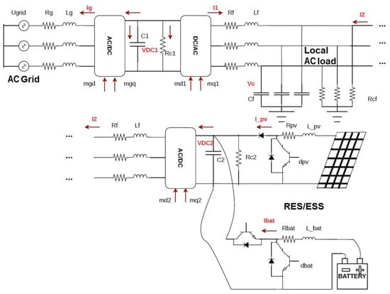
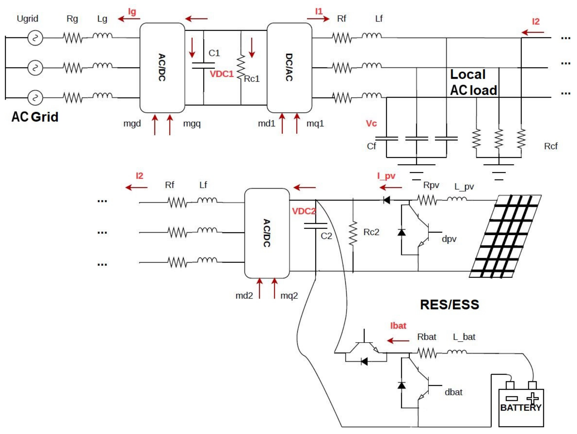
The present study considers a power system configuration as described above and shown in Figure 1. To analyze such a complex system, the exact nonlinear model is first formulated in the synchronously rotating d-q reference frame [21]. For all power converter interfaces, including the three AC/DC voltage source converters (VSCs) and the two DC/DC converters, mean-value dynamic models are used [22]. The DC/DC converters consist of a unidirectional converter at the PV output and a bidirectional converter at the ESS output. Instead of using linearized models around a particular equilibrium, the proposed model enables analysis of the system under dynamic, steady-state, and transient conditions within a unified framework. This allows reliably apply different scenarios that may result in different equilibria. The complete system model can be readily assessed for stability because it is in the CIAT form [23]. According to [23], the open-loop system is input-to-state stable (ISS) [24]. Furthermore, as proposed in [25], it satisfies the conditions to converge to equilibrium when bounded inputs are applied.
Figure 1.
Power system configuration.
Based on the nonlinear model, PI control schemes was applied [26,27,28] in a cascaded and suitably saturated mode, with current inner loops and voltage outer loops. The cascaded controllers’ outputs directly provide the duty-ratio components applied to each converter. While HVDC link control is implemented in a standard form [8,9,10], control tasks are required for sharing the RES power between the loads and the main grid with an efficient charging–discharging ESS operation. New control features are introduced in the command inputs of the RES/ESS side current and voltage controllers, resulting in coordinated control schemes that achieve the desired control objectives. Then, the PI controllers’ tasks, at the implementation level, can be summarized as follows: (1) voltage and reactive power regulation at both AC sides of the HVDC link, (2) maximum power point tracking (MPPT) at the PV side, and (3) coordinated control of the state of charge (SoC) at the ESS where charging–discharging demands are combined with solar irradiance and SoC. Based on the control capabilities, three different scenarios are considered: (1) a study of the whole system response under PV generation changes, (2) a permanent 3-phase short-circuit case at the mainland AC connection line, and (3) a large variation of the local load at the point of connection of the RES/ESS with the HVDC link. In all cases, the response of the system indicates stable and satisfactory performance under varying and dynamic conditions. The controllers effectively cooperate to achieve their tasks and to enhance the overall performance.
2. System Configuration and Modeling
2.1. Physical Configuration
Figure 1 shows the power system under study. In the upper-left part of Figure 1, the AC side of the HVDC link is connected to the mainland AC grid through a double AC line circuit. The other side of the HVDC link is connected to a local AC load at a common point where a PV cluster with an ESS is connected at the DC side of a local AC/DC VSC power device. To allow power flow in both directions, i.e., to and from the batteries, the PV cluster is regulated by an intermediate unidirectional DC/DC converter, while the ESS cluster is regulated by a bidirectional DC/DC converter.
2.2. Mathematical Description
According to the configuration presented in Figure 1, the mainland AC grid-side VSC converter dynamics of the HVDC link are described as follows:
where Lg and Rg are the AC grid-side line inductance and resistance, respectively; ω is the angular velocity, set to ; mgd and mgq are the duty-ratio inputs; Igd and Igq are the AC grid line currents; Ugd and Ugq are the AC grid infinite bus voltages; Vdc1 is the HVDC voltage; and C1 is the corresponding capacitance.
The equations at the local AC grid-side are:
where elements Lf, Rf, and Cf denote the filter inductance, parasitic resistance, and the filter capacitance, respectively; is the AC load resistance; mdi, mqi are the controlled duty-ratio inputs, Idi, Iqi are the filter currents, Vcd, Vcq are the local AC load d-q voltage components. The DC-link dynamics at the point of common connection of the DC/DC converters of the PV and the battery are given by:
where Vdc2 is the DC voltage at the point of connection, C2, is the capacitance and the corresponding parasitic resistance, dPV and dbat are the duty ratios of the DC/DC converters.
The equation of the DC/DC boost converter of the PV is described by:
where LPV, RPV are the inductance and parasitic resistance, respectively, of the boost-converter inductor and VPV is the DC voltage output of the PV installation.
For the battery, following linear version of the model was considered [29]. The dynamical equations combined with the equation of the bidirectional DC/DC converter connected at the output of the battery is given by:
where Lbat, Rbat are the inductance and parasitic resistance, respectively, of the bidirectional converter inductor, Ibat is the battery current in the parallel circuit Rts-Cts describe short-term transient phenomena, while Rtl-Ctl describe long-term transient phenomena, S is the battery SoC taking values between 0 and 1, Cc stems from the dynamics of the state of charge, and Voc is the open-circuit voltage when the battery is depleted, i.e., when the SoC is 0%. The constants a1, γ are positive.
2.3. Evaluating System Stability Properties
Considering the dynamic Equations (1)–(15), the complete open-loop description of the HVDC-based system can be compactly defined as a 15th order model, featuring a state vector xT = [Igd Igq Vdc1 Id1 Iq1 Id2 Iq2 Vcd Vcq Vdc2 IPV Ibat V1 V2 S].
Based on this formulation and nonlinear structure of the system, the investigation of its stability properties can be conducted by adopting a suitable and highly effective nonlinear analysis framework. Specifically, the first step of the analysis involves the introduction of an appropriate positive definite Lyapunov function expressed by:
with followed by considering the unforced version of the open-loop system (1)–(15), the derivative of (16) with respect to time can be calculated as:
where .
Based on (17) and by following a similar procedure as in [23], it can be concluded that the complete forced dynamic representation of (1)–(15) is ISS. Furthermore, under the condition of having bounded or at least piecewise bounded nonzero inputs acting on the open-loop system, according to Theorem 6 of [25], it can be additionally concluded that the system states converge to nonzero equilibria.
3. Control Tasks and Implementation
From a control design standpoint, the complete system topology shown in Figure 1 can be divided into two key subsystems; the mainland AC grid-side of the HVDC connection and the RES/ESS-dominated weak AC grid-side. Since both parts of the system have different regulation requirements, separate control tasks are required on each side of the DC-link. At the mainland AC grid-side, featuring long transmission lines to the infinite bus, the main control objective is to achieve seamless power transfer by guaranteeing strongly regulated HVDC link conditions, as well as to establish ideal voltage level and/or power quality properties by establishing e.g., a unity power factor. The weak local AC-side interface requires a more specialized control approach, mainly due to the absence of a stiff-grid AC voltage source, making the subsystem vulnerable to disturbances and abrupt dynamic transients, especially concerning the voltage stability of local loads. The VSC interface on this HVDC side is to maintain a constant AC voltage. As the subsystem incorporates PV sources, local loads, and an ESS cluster, different control targets have to coordinate between the third AC/DC VSC beyond the HVDC link and the two DC/DC power converters. The DC/DC interface of the PV plant ensures MPPT operation, matching the variable solar irradiance with the maximum power generation of the PV. Simultaneously, a novel coordinated scheme is proposed. First, the local AC/DC control regulates the active power flow through the HVDC link by considering the irradiance and SoC conditions in the AC current command while maintaining unity power factor at the local AC grid. Second, the bidirectional DC/DC control of the ESS cluster regulates the DC voltage and the charging/discharging operation using a variable DC voltage command based on the irradiance level.
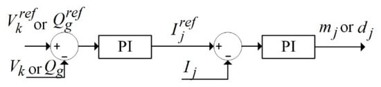
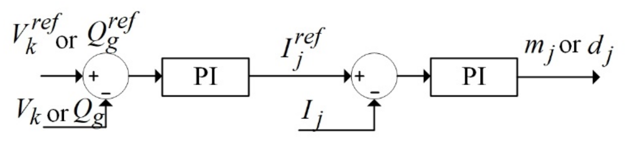
For the implementation of the control scheme described above, the control scheme uses the practical and widely used cascaded PI-controller structure. In particular, based on the well-known time-separation principle [30], a cascaded-type regulation structure is proposed, featuring fast inner-loop current controllers, driven by slower outer-loop voltage controllers, as shown in Figure 2. Figure 2 represents the control loops of each subsystem. Accordingly, subscript j is assumed to denote the specific controlled subsystem, i.e., j = gd or gq for the d-q-axis components on the mainland AC-grid side or j = di or qi, with i = 1, 2, when describing the weak-side AC d-q-axis current and voltage components, in the synchronously rotating reference frame. Similarly, j = PV or j = bat, for PV and ESS dc quantities, respectively.
Figure 2.
Proposed cascaded-type control block diagram.
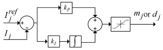
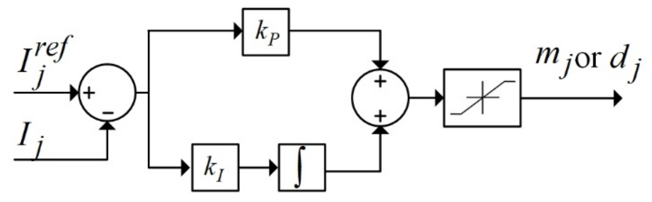
Based on this consideration, the structure of the current regulator used in this study is described by the following generic control law:
Accordingly, the duty-ratio command signals are provided directly to all power converter interfaces (all three AC/DC VSCs, as well as the DC/DC unidirectional and bidirectional ones). The current regulator structure is shown in Figure 3, which shows that contrary to commonly used PI-type inner-loop schemes [31], it does not feature any decoupling terms. Thus, the proposed inner-loop control design is particularly resilient to passive/lumped element variations or uncertainties.
Figure 3.
Proposed PI-type fast inner-loop current control structure.
Another important aspect of this particular structure is the inclusion of appropriate saturation mechanisms in the output of the regulators, aiming to restrict the duty-ratio command signals to their linear modulation region, hence guaranteeing safe operational conditions and satisfying the ISS property for the closed-loop system and state convergence at the equilibrium [26], as stated in Section 2.3.
For the outer loops, all voltage controllers, DC and AC, are described by:
with subscript j denoting the quantities referred to each part of the configuration, in the same manner as for the inner-loop controllers, while k = dc1, cd, cq or dc2 depending on the subsystem part where the control is applied.
It is noted that for the mainland AC grid-side control scheme, the current reference for the d-axis inner-loop controller is provided by a regulator of the form of (19), featuring j = gd and k = dc1, while for the q-axis current quantity regulation, the reference is being provided by a slower outer-loop reactive power controller of the form:
where Qg = 3/2(UgqIgd − UgdIgq) represents the reactive power being transferred from and to the infinite bus. This practically means that the mainland AC-side VSC substation is responsible for regulating both the DC voltage of the HVDC, as well as the AC voltage profile by injecting appropriately reactive power to the main grid through the long AC transmission line, thus affecting the power angle of the transmission line.
For the local AC grid-side control scheme, the local AC voltage d-q components are controlled by adopting (19), wherein j = d1 and k = cd, as well as j = q1 with k = cd. An obvious choice for setting the voltage references is to zero-out one of them, i.e., and setting the other one to nominal magnitude value, i.e., pu. In this manner, the voltage angle at the local load bus is fixed to a desired setpoint, while enabling the control of the reactive power flow towards the load bus through the q-axis component. At the second VSC converter beyond the HVDC link (interfacing the PV and ESS clusters with the rest of the system), two inner-loop current regulators in the form of (18) are applied, with j = d2, q2. Considering local operation under unity power factor, we select . For the other VSC output current component, the reference setpoint is selected in view of sharing the power provided to the VSC by the PV/ESS combination to the AC side, as , i.e., a function of S, the SoC, and G, the irradiance, as follows:
where Smin is selected to have the value 0.2 for S > Smin; otherwise, f = 0. The main insight of function f is to practically provide a linear relation between the irradiance and the desired reference current value. Therefore, parameter a represents the appropriate scaling, in SI units, experimentally validated for the operating voltage level.
In a similar manner, to integrate the critical control task of balancing power flow at the local AC grid-side with the ESS, the inner loop in the form of (18) is adopted, while the outer-loop DC voltage controller of the form of (19) for the bidirectional converter is tasked with regulating the DC-side voltage of the second VSC, namely Vdc2,, with command input , i.e., a function of the irradiance G,
where Gm is an arbitrary constant greater than the maximum of G (~1300 W/m2).
In Section 4, the effectiveness of applying (21) and (22) is completely validated, and the results show in detail that the desired response and power sharing are achieved.
Now, concerning the control strategy for the PV cluster, a standard MPPT scheme is adopted, based on the well-known perturb-and-observe (P&O) principle, commonly employed for maximum power extraction in such applications [32]. According to this approach, depending on the irradiance, an optimum reference is produced for the DC/DC boost converter input filter current at all times, which drives the local current controller designed in the generic form of (18).
It is noted that the local AC subsystem featured in this study is converter-dominated and, as such, all its RES units are interfaced through power converters, whereas only a small portion of the local demand may be assumed (if any) to include rotating inertia, i.e., induction motors. Therefore, the corresponding mechanical dynamics are reasonably neglected in the context of this analysis, while active power/frequency droop mechanisms are also not directly applicable. Moreover, the considered topology contains a single dominant voltage-establishing interface, while the remaining converter-interfaced units operate as a whole, in a common cluster, so reactive power sharing among parallel independent voltage-forming sources cannot be directly deployed as well. Nevertheless, the local voltage-regulating VSC is proposed to operate in a strictly grid-forming sense, establishing the local AC voltage magnitude and phase through an internally generated synchronous reference frame at nominal angular frequency. Since the remaining local converter is assumed to use this common reference frame, explicit PLL dynamics are also not included and analyzed as in standard cases [33], since, in the present formulation, grid-forming VSC operation may be applied. Thus, the main objective of this work is to investigate and apply effective coordinated control schemes, capable of sharing active power between different power sources (main grid, PV, ESS) and loads, and reactive power regulation for voltage modulation. Our procedure is deployed within the accurate nonlinear modeling framework of a representative modern power system configuration; extensions incorporating frequency and synchronization dynamics have other target objectives.
Finally, in order to further evaluate stability issues for the system with the proposed control scheme involved, the following observations are crucial. Initially, the proof of the open-loop stability properties, referred to as ISS and convergence, is the basis for integrating closed-loop stability in the same sense. As in the system, only at the inner-loop level, eight PI-type controllers are introduced, and an analogous number of outer-loop controllers are installed; rigorous stability analysis of such a high-order entire system becomes inefficient. However, under the assumption that the controllers’ command inputs always remain bounded, this constitutes an adequate condition for ensuring ISS. Nevertheless, a more accurate analysis needs either linearization around an operating point and linear system designs [34], or some advanced nonlinear methods compatible with the structure of converter-driven systems. In [35], such an analysis approach is developed by the authors for control designs similar to the ones proposed here, applied to an HVDC transmission link. This approach can be fundamental for extending the same analysis on the system under consideration, but it would be a large-scale cumbersome procedure based on some specific notions such as observability/detectability of nonlinear systems or persistency of excitation properties [36]; from a practical point of view, it is understood that this is not a straightforward procedure (case-based) and it is beyond the scope of this work at this time. It is certainly our intention to integrate this issue into future work for such large-scale controlled systems, in a general and fundamental manner.
4. System Studies and Results
4.1. RES/ESS Response Under PV Power Variations
The performance of the proposed coordinated control strategy is evaluated through detailed simulations conducted in MATLAB/Simulink (version R2023b, The MathWorks, Inc., Natick, MA, USA). Three different operating scenarios are considered to assess the system response under varying operating conditions and disturbances.
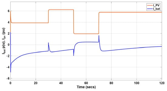
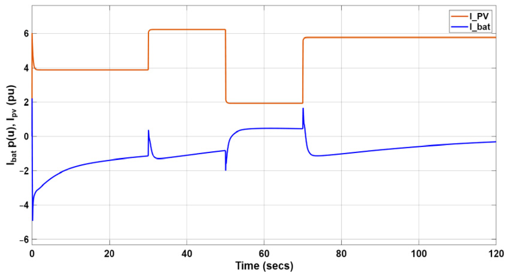
In the first scenario, irradiance variations are considered. Initially, irradiance reaches G = 600 W/m2, which increases at time instant t = 30 s to G = 1000 W/m2 (high-irradiance phase) while at t = 50 s it decreases to G = 300 W/m2 and finally, at t = 70 s increases again to high irradiance of G = 900 W/m2.
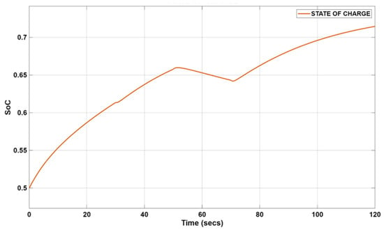
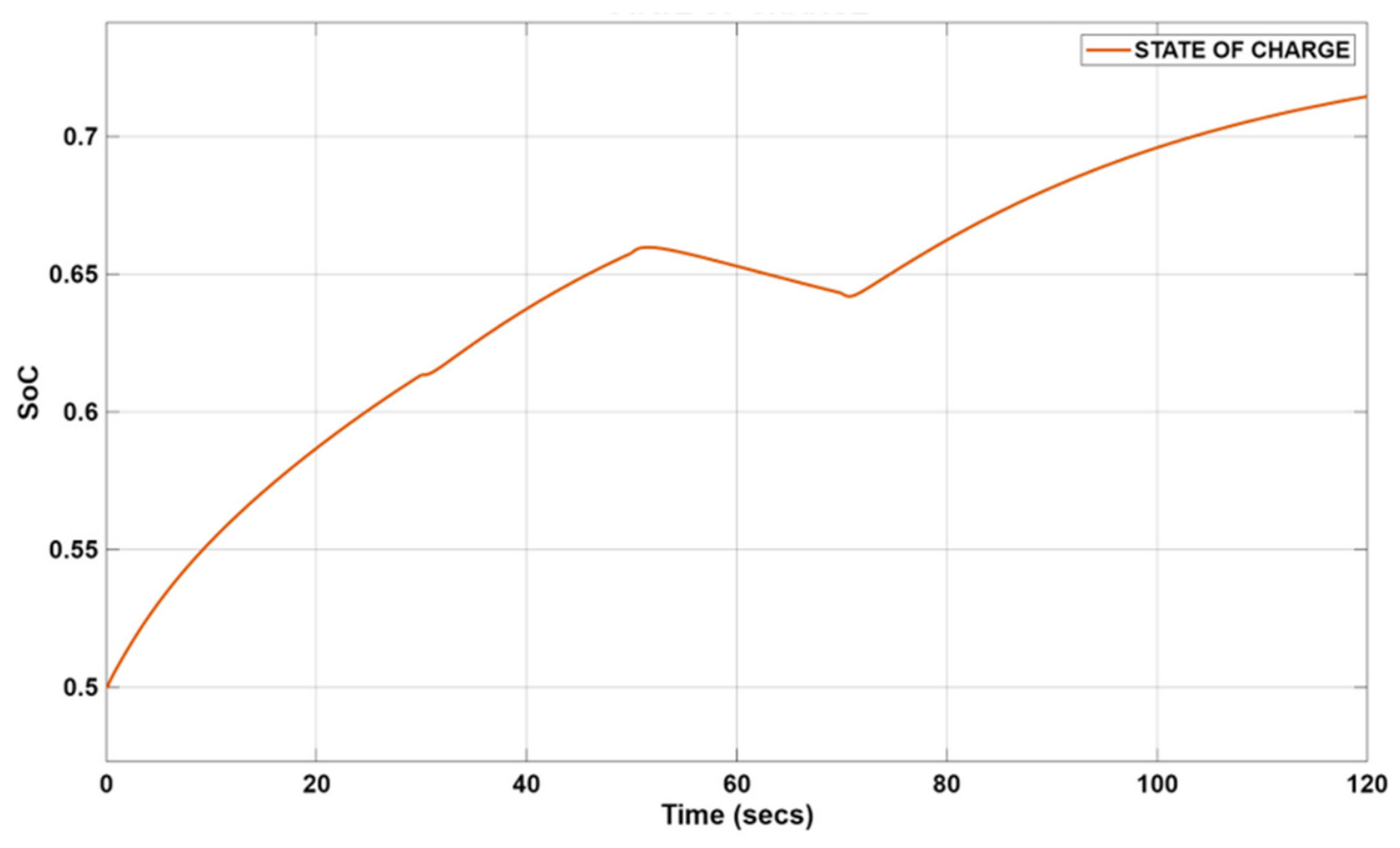
Figure 4 shows the produced PV current and the battery current, where the SoC, shown in Figure 5, starts from SoC = 50%. As shown in Figure 4 and Figure 5, the PV current is constant for constant irradiance, while the battery current is initially negative to charge the battery during the first two periods from t = 0 to 50 s. After t = 50 s until 70 s, when irradiance is low, the battery current becomes positive to discharge the battery and inject power into the grid, while the opposite occurs after t = 70 s when high irradiance appears again.
Figure 4.
Battery current Ibat (blue) and PV current Ipv (orange) vs. time (s).
Figure 5.
Battery SoC (S) vs. time (s).
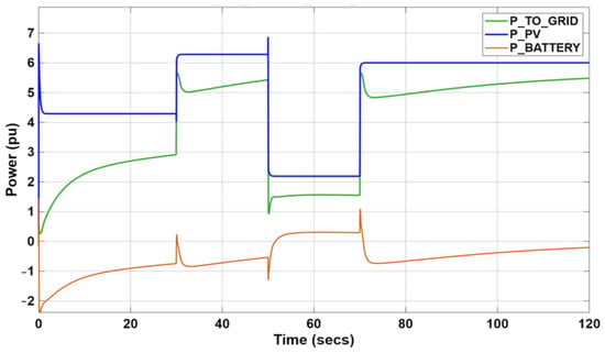
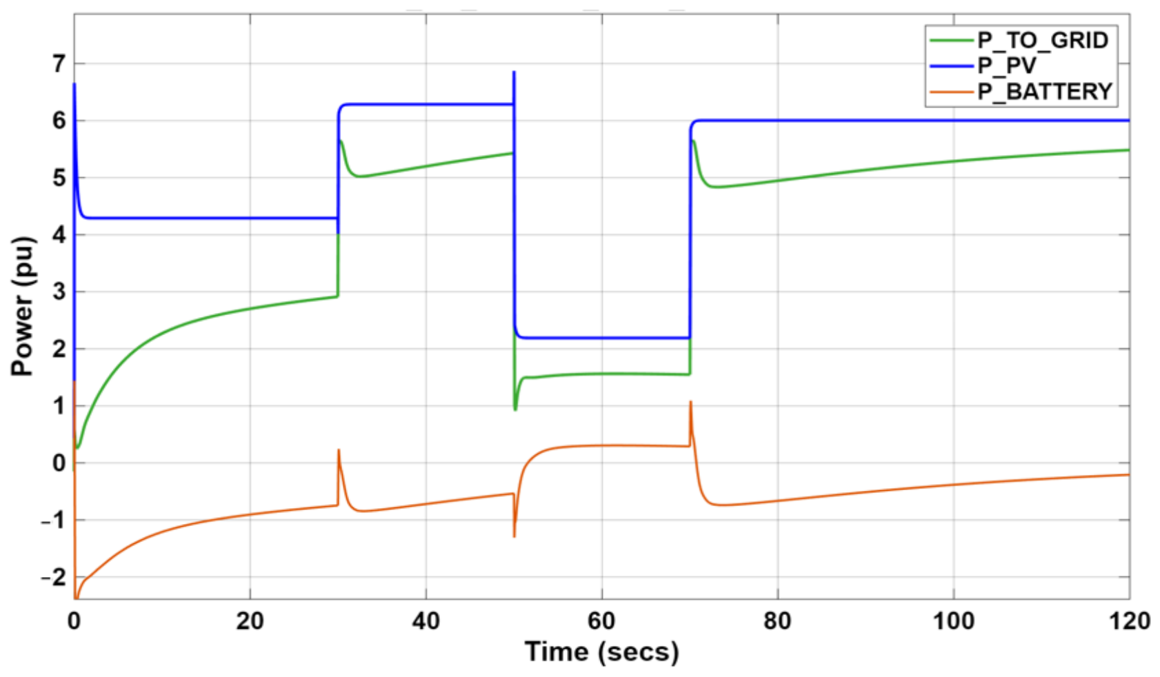
Similarly, as shown in Figure 6, the active power produced from the PV cluster is effectively shared between the battery and the mainland AC grid through the HVDC link. This is the result of the effective cooperative controls as driven by the command inputs (21) and (22).
Figure 6.
Active power of the PV, the battery, and the power injected to the main grid.
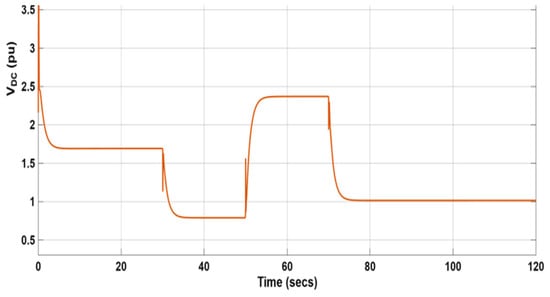
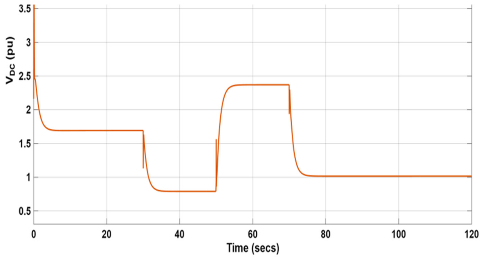
Note that the negative sign of the battery power means charging and the positive sign means discharging. It is also noticed that the almost constant difference between the PV-produced power and the sum of the ESS charging/discharging power and the power arriving at the mainland AC grid corresponds to the power feeding the local loads and all the dissipations. Finally, Figure 7 shows the DC local voltage response, which is regulated according to (22).
Figure 7.
DC voltage at the PV/ESS side.
4.2. Short-Circuit Case at the Mainland AC Connection Line
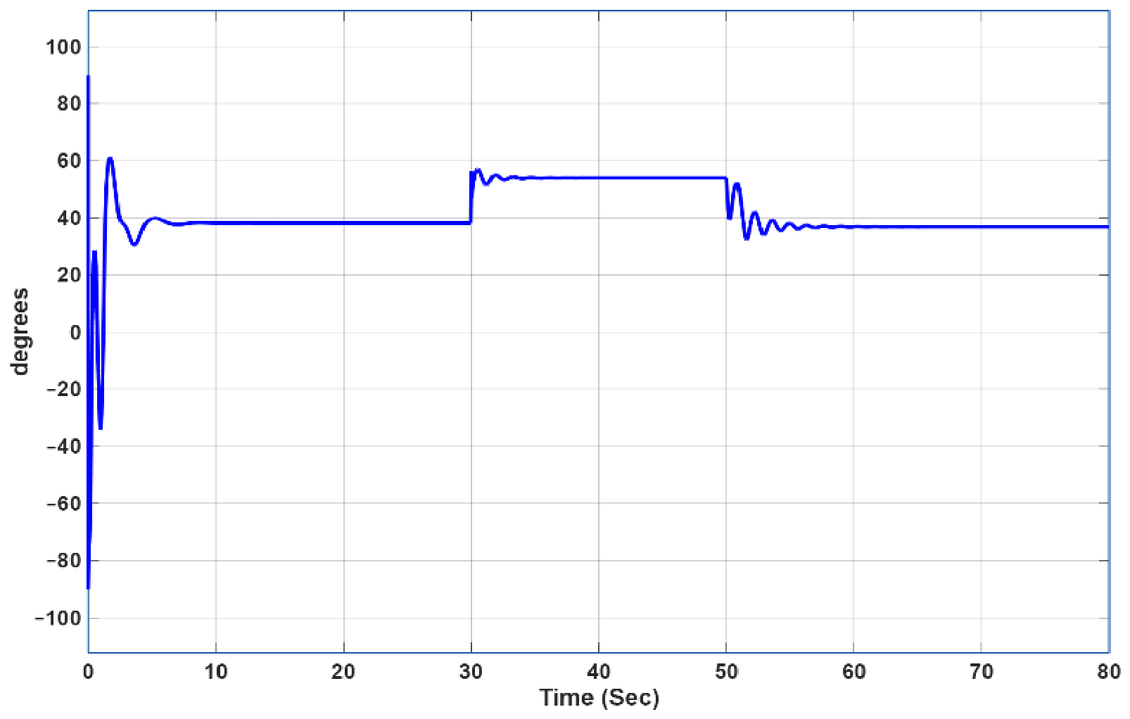
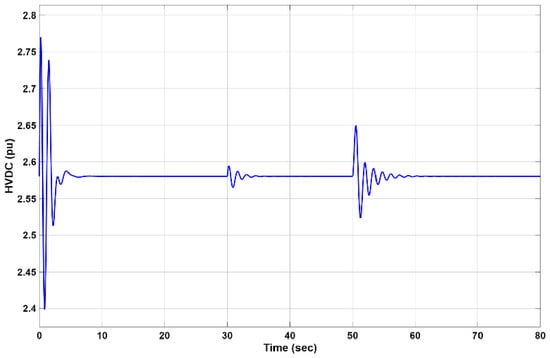
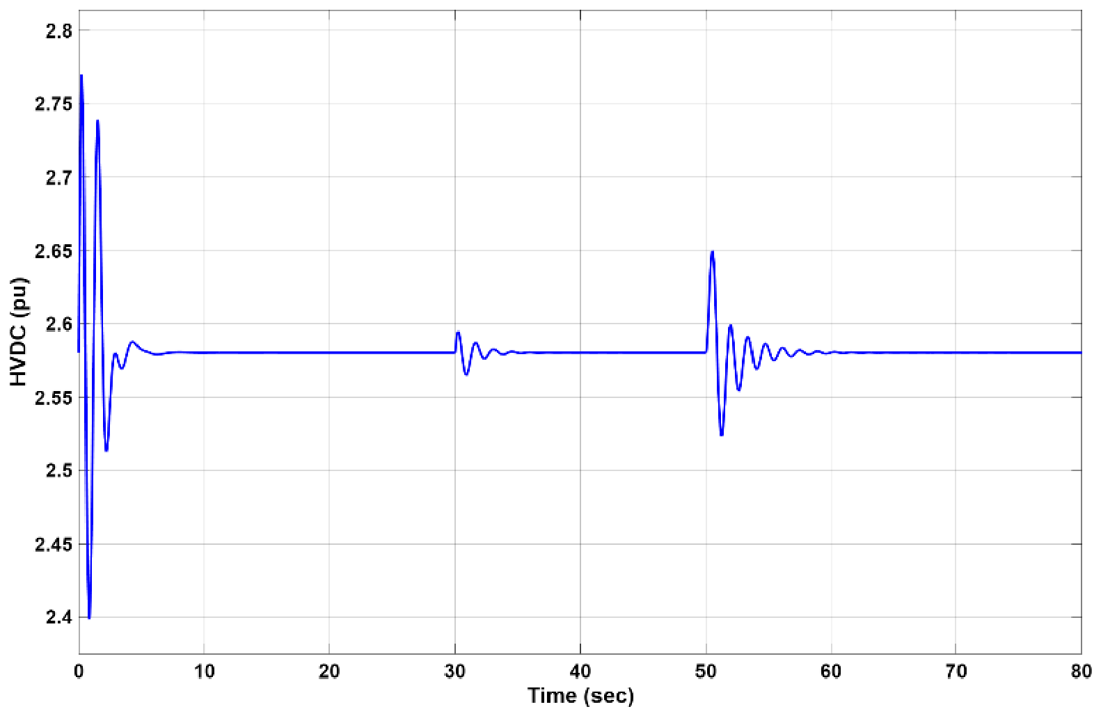
The system under study is connected to the mainland grid through a double-circuit long-distance line with parameters Rg, Lg. The system is initially considered to operate at steady state (as shown in Figure 8, Figure 9, Figure 10 and Figure 11 after a short transient initialization), with the excess of the produced power injected into the grid. At t = 30 s a permanent fault leads one of the two parallel AC lines to be disconnected. Then, the one-line transmission makes the connection with the main grid weaker (the ohmic resistance changes from to , and the inductance changes from 97.5 mH to 195 mH).
Figure 8.
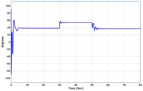
Voltage angle (degrees) versus time (s). The angle stabilizes near 38° after start-up, increases at t = 30 s due to grid weakening, and is restored at t = 50 s.
Figure 9.
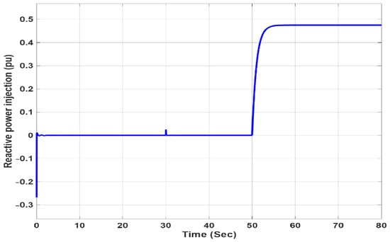
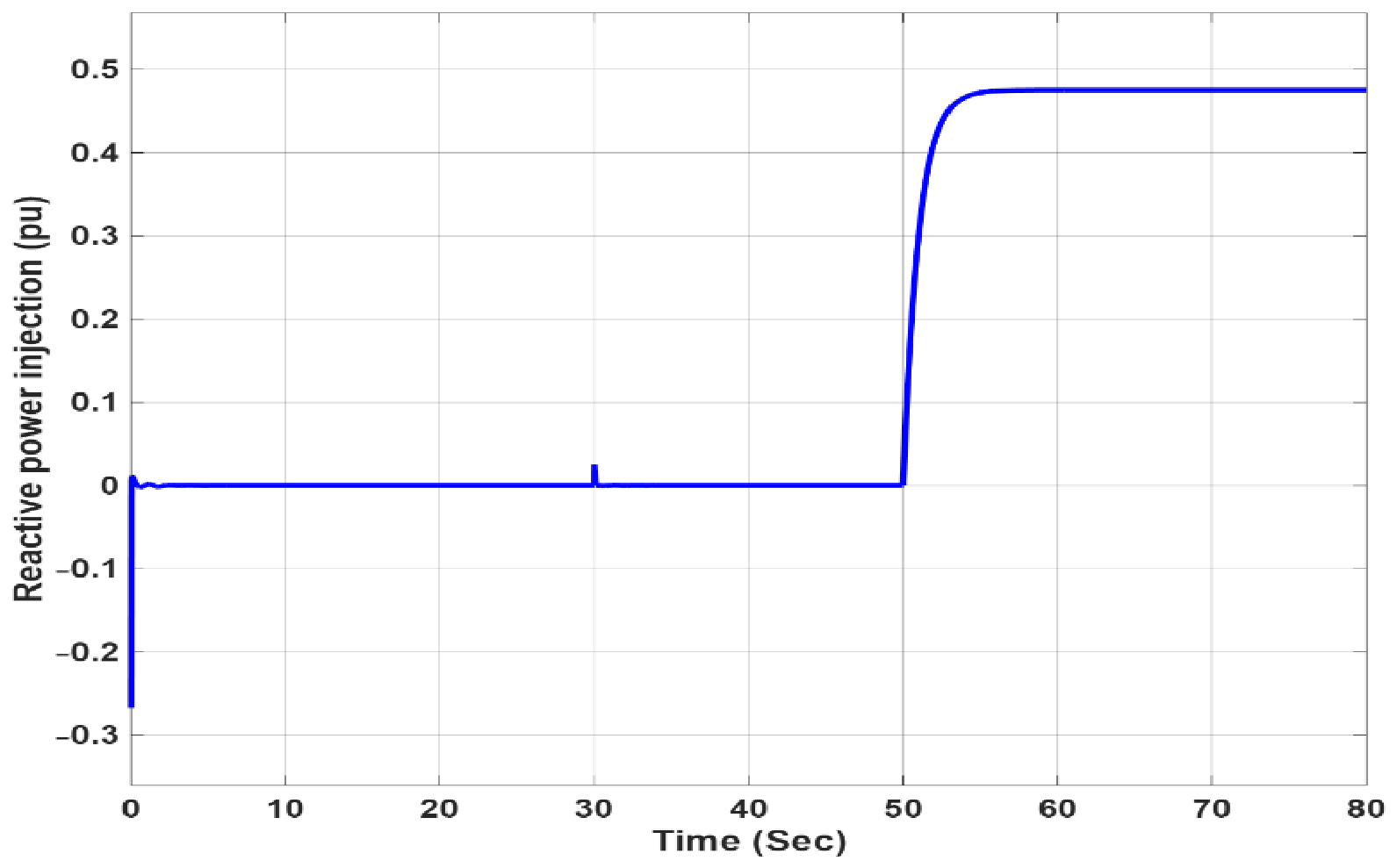
Reactive power Q vs. time (s). Q remains near zero until t = 50 s (step to 0.47 pu).
Figure 10.
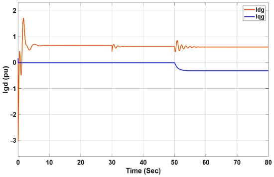
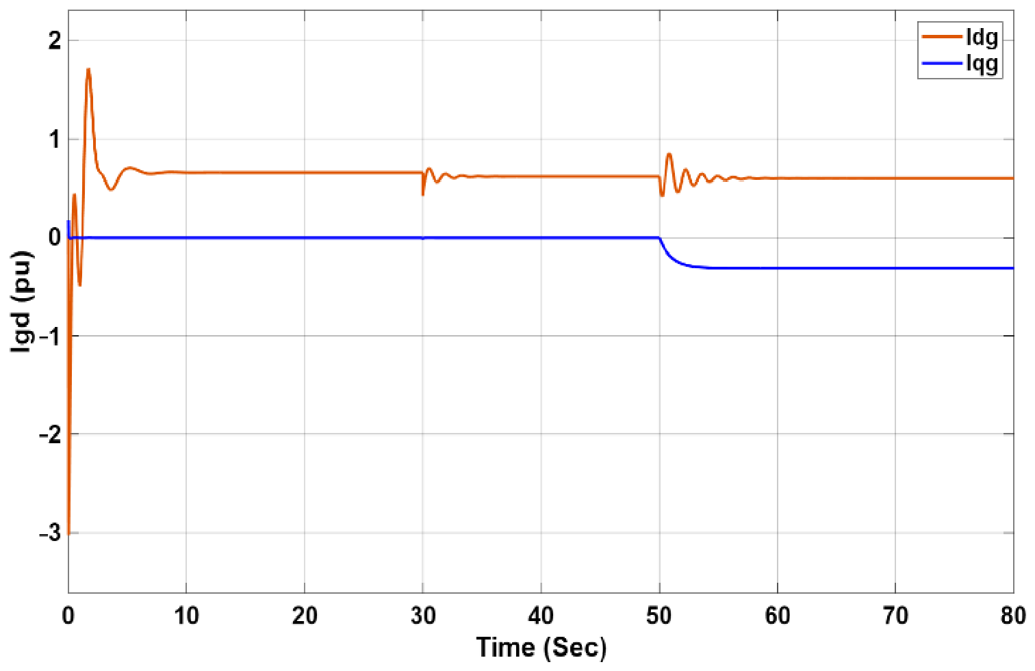
Grid-side dq currents Igd and Igq versus time. Igd controls the HVDC voltage, while Igq responds to the reactive power reference step at t = 50 s.
Figure 11.
HVDC Voltage regulated at its nominal value. After start-up, fast transients appear at t = 30 s and t = 50 s.
As shown in Figure 8, the AC line voltage angle before tripping is close to 38°, and after it converges to 56° since the AC-side VSC operates under a constant (set to zero) reactive power command input. At t = 50 s, the reactive power command input is increased to 0.47 pu. After t = 50 s, the power angle is restored to ~38°, whereas active power injection remains practically constant, and as shown in Figure 9, reactive injection is changing. One can make the same comments also for the current d, q components, as shown in Figure 10.
Finally, Figure 11 shows that after t = 30 s the HVDC voltage remains at its controlled constant value while the angle increases by ~18°. Also, after t = 50 s, the nominal HVDC voltage is restored with a larger transient.
4.3. Large Load Disturbances at the RES/ESS AC Side
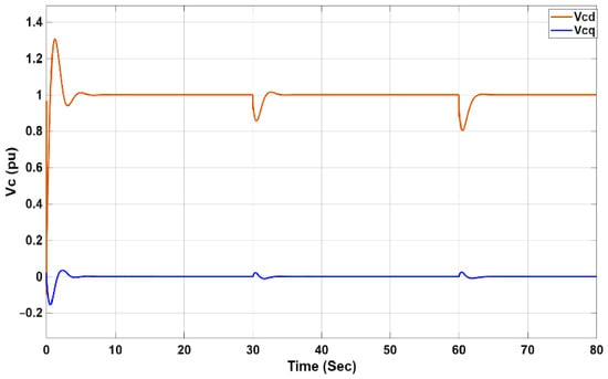
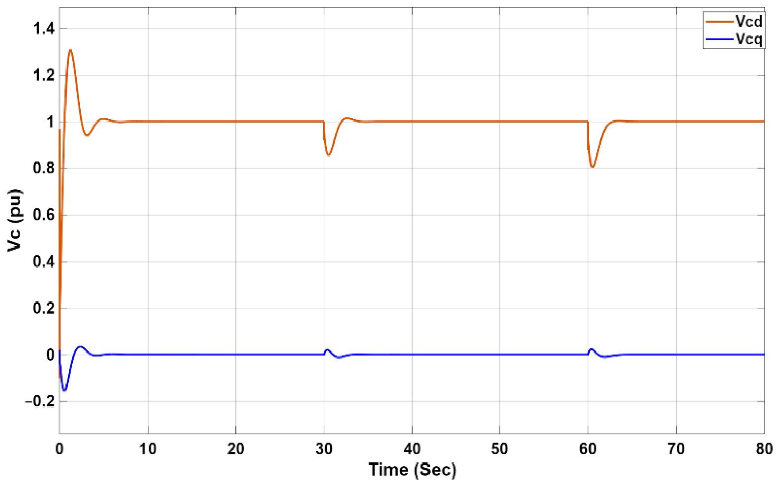
At the local AC side, the filter-side cascade controller of the VSC regulates Vcd to 1 pu and Vcq to 0. Large local AC load steps of 125% plus a 50% occur at t = 30 s and t = 60 s, respectively, under constant solar irradiance.
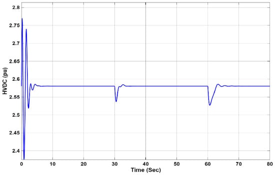
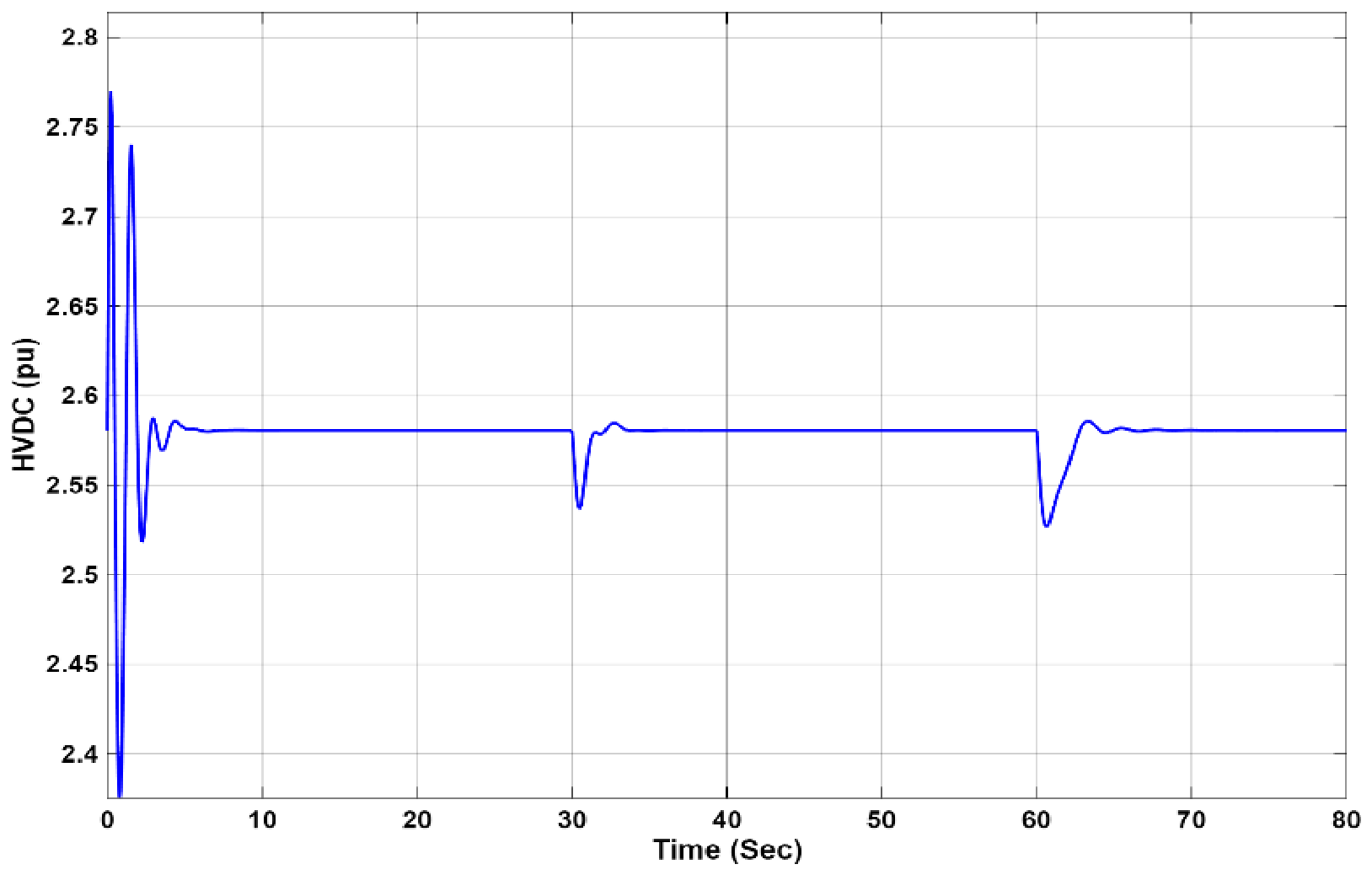
In Figure 12, the tasks of the PV/ESS side, VSC of the HVDC link, i.e., to maintain constant the d, q AC voltage components, are fully achieved, while the HVDC link DC voltage (Figure 13) remains at its nominal value after some fast transients during initialization and load changes.
Figure 12.
Filter capacitor voltages Vcd (orange) and Vcq (blue) vs. time (s). Vcd is regulated to 1 pu and Vcq to 0. Transients occur at start-up and at each load step (t = 30 and 60 s).
Figure 13.
Regulation of the HVDC DC-link voltage Vhvdc (pu) vs. time (s).
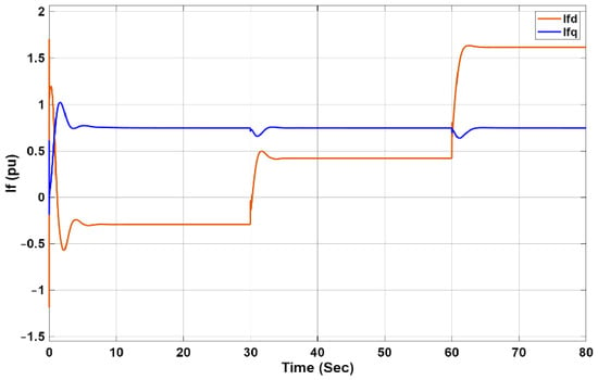
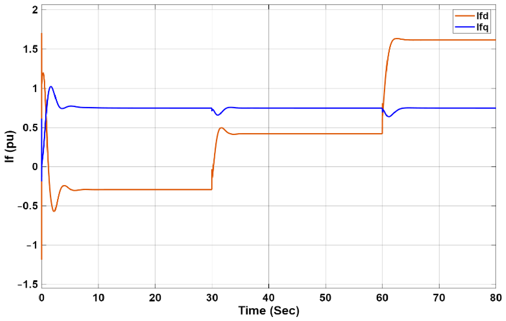
In Figure 14, the jump of the Ifd current at t = 30 s from negative to positive values is confirmed, i.e., changing direction from injection to the main grid to absorption from the main grid, to satisfy the local load increase. This response is verified similarly to the second AC load increase at t = 60 s.
Figure 14.
Filter-side d, q currents Ifd (orange) and Ifq (blue) vs. time (s), with Ifd changing from negative to positive at t = 30 s.
5. Conclusions
This paper presents extended studies that involve AC voltage/reactive power regulation in both the AC sides of a HVDC-based power transmission system, where new coordinated strategies are introduced to share the active power locally produced by a PV cluster on one of the AC sides between the HVDC link and the associated renewable energy source/energy storage system (RES/ESS). Simulation experiments were conducted using the accurate nonlinear model of the complete system, in which the proposed new control techniques are applied. The system responses under challenging operating scenarios fully confirm the expected performance in accordance with the controllers’ objective tasks.
Author Contributions
Conceptualization, N.C.P. and A.T.A.; methodology, N.C.P. and A.T.A.; validation, N.C.P., P.C.P. and T.A.A.; formal analysis, N.C.P., P.C.P., T.A.A. and G.C.K.; investigation, N.C.P., P.C.P. and T.A.A.; data curation, N.C.P.; writing—original draft preparation, N.C.P. and A.T.A.; writing—review and editing, N.C.P., P.C.P., T.A.A., G.C.K. and A.T.A.; visualization, N.C.P.; supervision, A.T.A., P.C.P. and G.C.K.; project administration, A.T.A. All authors have read and agreed to the published version of the manuscript.
Funding
This research was partially funded by the European Union through the Digital Europe Programme under the EUDOROS project (Grant Agreement No. 101158605), through its SPF (Sea Plane Fortress) subproject.
Institutional Review Board Statement
Not applicable.
Informed Consent Statement
Not applicable.
Data Availability Statement
The data supporting the findings of this study are available from the corresponding authors upon reasonable request.
Conflicts of Interest
The authors declare no conflicts of interest.
References
- Renewable Energy Accounted for Nearly 30% of Global Electricity Generation in 2023; International Energy Agency (IEA): Paris, France, 2026; Available online: https://www.iea.org/ (accessed on 9 June 2026).
- Cheng, T.; Chen, R.; Lin, N.; Liang, T.; Dinavahi, V. Machine-Learning-Reinforced Massively Parallel Transient Simulation for Large-Scale Renewable-Energy-Integrated Power Systems. IEEE Trans. Power Syst. 2025, 40, 970–981. [Google Scholar] [CrossRef] [Scilit]
- Mohammed, Z.; Kaoutar, T.; Abdelghani, E.O.; Belkacem, T. Enhancing Grid-Connected Photovoltaic Power System Performance Using Fuzzy P&O Approach. Eng. Proc. 2025, 112, 25. [Google Scholar] [CrossRef] [Scilit]
- Tamoor, M.; Bhatti, A.R.; Farhan, M.; Zaka, M.A.; ZakaUllah, P. Solar Energy Capacity Assessment and Performance Evaluation of Designed Grid-Connected Photovoltaic Systems. Eng. Proc. 2023, 37, 39. [Google Scholar] [CrossRef] [Scilit]
- Brik, A.; Kouba, N.E.Y.; Ladjici, A.A. Enhancement of Dynamic Microgrid Stability Under Climatic Changes Using Multiple Energy Storage Systems. Eng. Proc. 2026, 117, 66. [Google Scholar] [CrossRef] [Scilit]
- Jiang-Häfner, Y.; Lundberg, P. VSC HVDC Transmission Supporting Variable Electricity Generation; CIGRE: Paris, France, 2016. [Google Scholar]
- ENTSO-E. Network Code on High Voltage Direct Current Connections and DC-Connected Power Park Modules; Draft; ENTSO-E: Brussels, Belgium, 2014. [Google Scholar]
- Hannan, M.A.; Hussin, I.; Ker, P.J.; Hoque, M.M.; Hossain Lipu, M.S.; Hussain, A.; Rahman, M.S.A.; Faizal, C.W.M.; Blaabjerg, F. Advanced Control Strategies of VSC Based HVDC Transmission System: Issues and Potential Recommendations. IEEE Access 2018, 6, 78352–78369. [Google Scholar] [CrossRef] [Scilit]
- Aragues Penalba, M.; Gomis-Bellmunt, O.; Martins, M. Coordinated Control for an Offshore Wind Power Plant to Provide Fault Ride Through Capability. IEEE Trans. Sustain. Energy 2014, 5, 1253–1261. [Google Scholar] [CrossRef] [Scilit]
- Feltes, C.; Wrede, H.; Koch, F.W.; Erlich, I. Enhanced Fault Ride-Through Method for Wind Farms Connected to the Grid Through VSC-Based HVDC Transmission. IEEE Trans. Power Syst. 2009, 24, 1537–1546. [Google Scholar] [CrossRef] [Scilit]
- Sakamuri, J.N.; Rather, Z.H.; Rimez, J.; Altin, M.; Goksu, O.; Cutululis, N.A. Coordinated Voltage Control in Offshore HVDC Connected Cluster of Wind Power Plants. IEEE Trans. Sustain. Energy 2016, 7, 1592–1601. [Google Scholar] [CrossRef] [Scilit]
- Abbey, X.; Adebiyi, A.A. A Coordinated HVDC and Energy Storage Framework for Grid Stability in Renewable Systems. Eng. Proc. 2026, 140, 44. [Google Scholar] [CrossRef] [Scilit]
- Weigt, H.; Jeske, T.; Leuthold, F.; Von Hirschhausen, C. “Take the Long Way Down”: Integration of Large-Scale North Sea Wind Using HVDC Transmission. Energy Policy 2010, 38, 3164–3173. [Google Scholar] [CrossRef] [Scilit]
- Karystianos, M.; Kabouris, Y.; Koronides, T.; Sofroniou, S. Operation of the Electrical System of Crete in Interconnection with the Mainland Grid: A Stability Study. In Proceedings of the 2013 IREP Symposium Bulk Power System Dynamics and Control—IX Optimization, Security and Control of the Emerging Power Grid, Rethymno, Greece, 25–30 August 2013; IEEE: Piscataway, NJ, USA, 2013; pp. 1–8. [Google Scholar] [CrossRef] [Scilit]
- Zhang, Y.; Yuan, M.; Mao, Z.; Tao, S.; Huang, X.; Sun, Y. Research on Behavior Incentives of User-Side Battery by Behavioral Economics. In Proceedings of the 2021 4th International Conference on Energy, Electrical and Power Engineering (CEEPE), Chongqing, China, 23–25 April 2021; IEEE: Piscataway, NJ, USA, 2021; pp. 108–114. [Google Scholar] [CrossRef] [Scilit]
- Arsalis, A.; Papanastasiou, P.; Georghiou, G.E. A Comparative Review of Lithium-Ion Battery and Regenerative Hydrogen Fuel Cell Technologies for Integration with Photovoltaic Applications. Renew. Energy 2022, 191, 943–960. [Google Scholar] [CrossRef] [Scilit]
- European Commission; Directorate General for Economic and Financial Affairs. The Development of Renewable Energy in the Electricity Market; Publications Office: Luxembourg, 2023. [Google Scholar] [CrossRef]
- Liang, X. Emerging Power Quality Challenges Due to Integration of Renewable Energy Sources. IEEE Trans. Ind. Appl. 2017, 53, 855–866. [Google Scholar] [CrossRef] [Scilit]
- Gomis-Bellmunt, O.; Hassan, F.; Barker, C.; Egea-Alvarez, A. Capability Curves of a VSC-HVDC Connected to a Weak AC Grid Considering Stability and Power Limits. In Proceedings of the 11th IET International Conference on AC and DC Power Transmission, Birmingham, UK, 10–12 February 2015; Institution of Engineering and Technology: Singapore, 2015; p. 053. [Google Scholar] [CrossRef] [Scilit]
- Yan, K.; Li, G.; Zhang, R.; Xu, Y.; Jiang, T.; Li, X. Frequency Control and Optimal Operation of Low-Inertia Power Systems with HVDC and Renewable Energy: A Review. IEEE Trans. Power Syst. 2024, 39, 4279–4295. [Google Scholar] [CrossRef] [Scilit]
- Zonetti, D.; Ortega, R.; Benchaib, A. Modeling and Control of HVDC Transmission Systems from Theory to Practice and Back. Control Eng. Pract. 2015, 45, 133–146. [Google Scholar] [CrossRef] [Scilit]
- Sigrist, L.; Echavarren, F.; Rouco, L.; Panciatici, P. A Fundamental Study on the Impact of HVDC Lines on Transient Stability of Power Systems. In Proceedings of the 2015 IEEE Eindhoven PowerTech, Eindhoven, The Netherlands, 29 June–2 July 2015; IEEE: Piscataway, NJ, USA, 2015; pp. 1–6. [Google Scholar] [CrossRef] [Scilit]
- Papageorgiou, P.C.; Alexandridis, A.T. Controlled Impedance-Admittance-Torque Nonlinear Modeling and Analysis of Modern Power Systems. Energies 2020, 13, 2461. [Google Scholar] [CrossRef] [Scilit]
- Sontag, E.D.; Wang, Y. On Characterizations of the Input-to-State Stability Property. Syst. Control Lett. 1995, 24, 351–359. [Google Scholar] [CrossRef] [Scilit]
- Alexandridis, A.T. Studying State Convergence of Input-to-State Stable Systems with Applications to Power System Analysis. Energies 2019, 13, 92. [Google Scholar] [CrossRef] [Scilit]
- Papageorgiou, P.C.; Alexandridis, A.T.; Dikaiakos, C. Voltage and Power Regulators Guaranteeing Stability of DC-Links Between DERs and the Electricity Grid. In Proceedings of the 2018 IEEE International Conference on Industrial Technology (ICIT), Lyon, France, 19–22 February 2018; IEEE: Piscataway, NJ, USA, 2018; pp. 1320–1325. [Google Scholar] [CrossRef] [Scilit]
- Evangelopoulos, V.; Karaitsi, M.-E.; Kavvathas, T.; Alexandridis, T.; Konstantopoulos, G.C. Combined Synchronverter-VSM Based HVDC Transmission Design with Power-Hardware-In-the-Loop (PHIL) Implementation. In Proceedings of the 2025 IEEE PES Conference on Innovative Smart Grid Technologies—Middle East (ISGT Middle East), Dubai, United Arab Emirates, 23–26 November 2025; IEEE: Piscataway, NJ, USA, 2025; pp. 1–5. [Google Scholar] [CrossRef] [Scilit]
- Papageorgiou, P.C.; Krommydas, K.F.; Alexandridis, A.T. Validation of Novel PLL-Driven PI Control Schemes on Supporting VSIs in Weak AC-Connections. Energies 2020, 13, 1373. [Google Scholar] [CrossRef] [Scilit]
- Krommydas, K.F.; Alexandridis, A.T. Modular Control Design and Stability Analysis of Isolated PV-Source/Battery-Storage Distributed Generation Systems. IEEE J. Emerg. Sel. Top. Circuits Syst. 2015, 5, 372–382. [Google Scholar] [CrossRef] [Scilit]
- Slotine, J.-J.E.; Li, W. Applied Nonlinear Control; Prentice Hall: Englewood Cliffs, NJ, USA, 1991. [Google Scholar]
- Yazdani, A.; Iravani, R. Voltage-Sourced Converters in Power Systems: Modeling, Control, and Applications, 1st ed.; Wiley: Hoboken, NJ, USA, 2010. [Google Scholar] [CrossRef] [Scilit]
- Krommydas, K.F.; Alexandridis, A.T. Nonlinear Analysis Methods Applied on Grid-Connected Photovoltaic Systems Driven by Power Electronic Converters. IEEE J. Emerg. Sel. Top. Power Electron. 2020, 8, 3293–3306. [Google Scholar] [CrossRef] [Scilit]
- Alexandridis, T.A.; Papageorgiou, P.C.; Konstantopoulos, G.C. Global Stability Analysis of PI-Controlled Grid-Following Inverters Incorporating the Time-Varying Nature of the PLL Mechanism. In Proceedings of the 2026 34th Mediterranean Conference on Control and Automation (MED), Ancona, Italy, 23–26 June 2026; IEEE: Piscataway, NJ, USA, 2026; pp. 370–375. [Google Scholar] [CrossRef] [Scilit]
- Alexandridis, A.T. Design of Output Feedback Controllers and Output Observers. IEE Proc. Control Theory Appl. 1999, 146, 108–112. [Google Scholar] [CrossRef] [Scilit]
- Papageorgiou, P.C.; Alexandridis, A.T. Innovations on the Control of VSC-Based DC-Links Connecting Distributed Generation to the Grid. In Proceedings of the IECON 2019—45th Annual Conference of the IEEE Industrial Electronics Society, Lisbon, Portugal, 14–17 October 2019; IEEE: Piscataway, NJ, USA, 2019; pp. 3919–3924. [Google Scholar] [CrossRef] [Scilit]
- Panteley, E.; Loria, A.; Teel, A. Relaxed Persistency of Excitation for Uniform Asymptotic Stability. IEEE Trans. Autom. Control 2001, 46, 1874–1886. [Google Scholar] [CrossRef] [Scilit]
Disclaimer/Publisher’s Note: The statements, opinions and data contained in all publications are solely those of the individual author(s) and contributor(s) and not of MDPI and/or the editor(s). MDPI and/or the editor(s) disclaim responsibility for any injury to people or property resulting from any ideas, methods, instructions or products referred to in the content. |
© 2026 by the authors. Licensee MDPI, Basel, Switzerland. This article is an open access article distributed under the terms and conditions of the Creative Commons Attribution (CC BY) license.