


Abstract
This paper presents a low-cost rail-extended Tripteron-type translational parallel robot in which the three actuated prismatic joints are implemented as belt-driven sliders on three parallel linear rails. By co-planar placement of the three prismatic axes and extending their stroke along the rail direction, the reachable workspace is significantly enlarged while preserving the original PRRR limb structure and the decoupled translational motion concept. A compact kinematic model is derived using a limb plane-constraint formulation: each limb constrains the tool center point (TCP) to a plane with constant normal in the base frame, yielding an explicit inverse kinematics expression and a linear forward kinematics solution as the intersection of three planes. Differential kinematics is obtained in closed form, leading to a constant Jacobian suitable for real-time implementation and sensitivity assessment via matrix conditioning. The operational workspace is evaluated numerically under joint-stroke limits and visualized through planar projections. For control implementation, an EtherCAT-based multi-axis architecture with Distributed Clocks synchronization is adopted in TwinCAT 3, and smooth point-to-point motion is generated using an LSPB trajectory profile. A fabricated prototype with timing-belt transmissions is built and experimentally validated. Positioning tests on randomly selected points with repetitions per point, measured by an external non-contact system, report a mean Euclidean positioning error of mm, demonstrating repeatable translational motion and confirming the feasibility of the proposed belt-driven rail extension for extended-reach applications.
1. Introduction
In the context of Industry 4.0, manufacturing is shifting toward digitalisation, connectivity, and autonomy, where robots serve as a crucial execution layer to increase productivity, reduce quality variation, and enable flexible production-line configurations [1,2,3]. Beyond manufacturing, robots have also been rapidly developed for scenarios that require natural human interaction and agile operation in complex environments, such as delivery systems and human–robot interaction platforms [4,5]. Among mechanical solutions for industrial robots, parallel robots stand out thanks to load distribution across multiple limbs, a low moving mass, and high stiffness, making them suitable for pick-and-place and light machining tasks [6]. These properties have driven the development of three-degree-of-freedom (3-DoF) translational robots in the Cartesian-parallel family, where motion along the axes can be clearly decoupled either at the mechanism level or through the Jacobian mapping, thereby simplifying control modelling [7]. The Tripteron is a representative member of this group. It features three similar kinematic limbs and a structure designed for motion decoupling, which facilitates both forward and inverse kinematics as well as multi-axis control implementation [8]. These advances have strengthened both industrial robotics and research-oriented platforms, including humanoid robots [9], by improving deployment robustness, motion quality, and system integration across real-world operating conditions.
However, purely translational parallel robots often face workspace limitations due to geometric constraints, mechanical interference, and changes in transmission conditions as the operation point approaches the workspace boundary [10]. In near-singular regions, actuation errors and assembly errors tend to be strongly amplified into end-effector position errors, a phenomenon described in singularity analyses of closed kinematic chains [11]. To evaluate transmission quality across the workspace, metrics such as manipulability are used to relate the Jacobian structure to the ability to generate velocity and force in different directions, thus reflecting the loss of dexterity when approaching workspace limits [12]. From a modelling perspective, the Tripteron has been studied using Newton–Euler-based dynamic models and torque computation approaches, providing a basis for trajectory-tracking controller design [13,14]. Recent results further highlight the role of system identification and vibration compensation when the mechanism exhibits noticeable compliance, especially in the presence of long links, joint backlash, or equivalent elastic elements in the drivetrain [15]. Experimentally, studies on kinematic identification and encoder-feedback position control for decoupled 3-DoF mechanisms have provided useful test procedures for prototyping stages [16]. At the drive-control level, robust controllers that reduce oscillations and limit chattering on servo drives have also been investigated, improving trajectory tracking quality in multi-axis operation [17]. In another application direction, the Tripteron principle has been transferred to compliant triaxial mechanisms to achieve precise translational motion at the micro-scale, demonstrating the generality of axis-decoupled motion concepts [18].
To extend the reachable workspace without abandoning the original control structure, one research direction focuses on reconfigurable parallel mechanisms, where geometry or actuation modes can be changed to improve workspace, avoid unfavourable regions, and adapt to tasks [19]. In this line of work, adding a linear rail motion to the actuation module has been analysed as a variant that increases reach while preserving the core kinematics of the mechanism, exemplified by the kinematic analysis of a one-rail Tripteron variant [20]. In parallel, prototype parallel robots based on linear-delta architectures have also shown the benefit of combining a parallel mechanism with linear guidance to extend the workspace along a long axis [21]. Nevertheless, existing studies still lack a complete presentation of a low-cost belt-driven system, covering mechanical design, kinematic verification, real-time control implementation, and prototype-level experimental evaluation [20,22].
To address this gap, this paper presents an extended Tripteron structure mounted on parallel rails, where the three prismatic joints are placed on the same plane and translate along rails to increase the reach along the main direction, while preserving the PRRR kinematics of each limb [8]. Compared with existing Tripteron-type mechanisms, the main improvement of the proposed design is the use of rail-mounted prismatic sliders to increase the available linear stroke without changing the basic translational constraint principle. The prototype is implemented using an industrial control architecture with EtherCAT and Distributed Clocks synchronisation to ensure multi-axis phase alignment, while the control program is realised in TwinCAT 3 using PLC function blocks and NC PTP modules [23,24,25]. For trajectory generation, the study adopts trapezoidal velocity profiles and LSPB to limit acceleration and improve motion smoothness, and it also refers to jerk-limited trajectory results to reduce vibration excitation at high speeds [26,27,28,29]. The motion planning framework is compared with smooth and time-optimal trajectory generation methods for industrial robots, as well as exponential-function trajectory generators for point-to-point motion [30,31,32]. Since the prototype uses belt drives to reduce cost and moving mass, this paper also discusses compliance and transmission errors in belt-driven systems, linking them to robust control models for belt-driven linear systems and industrial belt design guidelines [22,33]. The experimental results in this study focus on position error evaluation using encoder feedback at the prototype level, rather than a full ISO 9283 [34]. Test campaign, and kinematic calibration is considered as a future upgrade to improve absolute accuracy [34,35]. The remainder of the paper presents the mechanical design and kinematic modelling, describes the real-time control implementation and trajectory generation method, and then reports experiments and discusses prototype limitations and future development directions.
2. Materials and Methods
2.1. Reference Frame and Joint-Variable Parameterisation
A fixed Cartesian reference frame is attached to the robot base to ensure consistent geometric design and kinematic derivation, independent of sensing placement and actuation hardware. Under the pure-translation assumption, the end-effector state is fully described by the TCP position.
and the mechanism configuration is described by the three prismatic displacements
for limb i, the slider attachment point is parameterised by
where is the design position at and is the unit prismatic direction. With the prismatic axes aligned to the base X axis,
2.2. Planar Constraint of Each Limb and Inverse Kinematics
Each limb constrains the TCP E to lie on a plane expressed in the base frame. The plane translates with the slider displacement while its orientation remains fixed in the base frame, which is satisfied when the passive revolute axes in each limb keep fixed directions and the platform is constrained to pure translation. Hence the plane normal is constant, while the plane location varies through . The normal can be computed from three non-collinear points on , passive joint centres , using
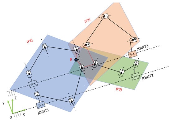
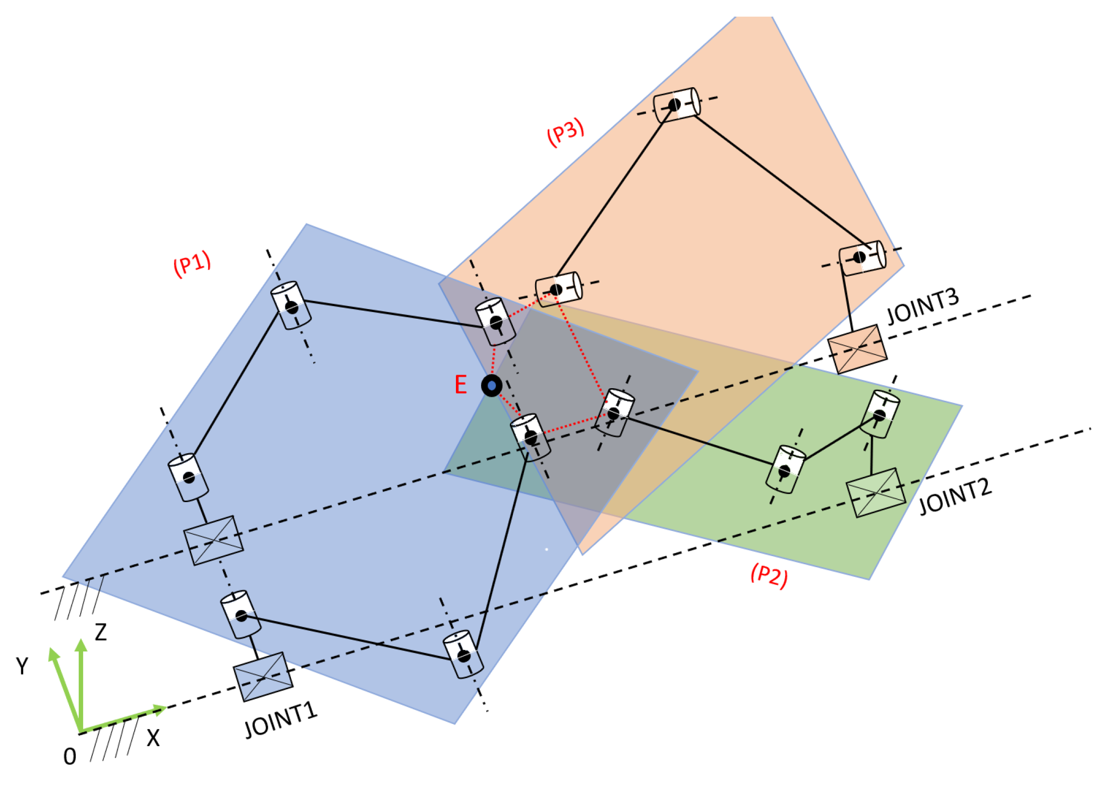
As shown in Figure 1, the TCP lies on all three planes. For limb i, the point–normal plane equation through is
so the limb constraint at the TCP becomes
Figure 1.
Intersection principle of the three limb planes at the tool center point.
2.3. Forward Kinematics and Singularity Condition
Forward kinematics is obtained from the intersection of the three limb planes, which can be written as a linear system in the TCP position. Stacking the plane normals and plane constants yields
The forward kinematics then satisfies and admits a unique solution when , giving
Since the plane normals are constant in the base frame, is a design constant. A singularity may occur when the three limb constraint planes become linearly dependent, corresponding to . In this condition, the intersection of the three planes is not uniquely defined and the TCP position cannot be reliably determined from the three prismatic displacements. Therefore, singularity is avoided by enforcing at the design stage, while characterises how geometric errors and perturbations in are amplified into TCP position errors. In practical operation, workspace-boundary limitations may also occur due to passive-joint limits, link interference, and rail stroke constraints.
2.4. Differential Kinematics and the Jacobian Matrix
Taking the time derivative of (7) with gives
Stacking the three limbs yields
with the diagonal projection matrix
For , the joint-to-task velocity mapping is
with constant and , the Jacobian is configuration-independent, and sensitivity is primarily governed by .
2.5. Operational Workspace and Limits Due to Stroke Constraints
The admissible joint domain is defined by stroke bounds
The operational workspace consists of TCP positions whose inverse kinematics satisfy the stroke limits and additional mechanical constraints, represented by inequality functions
Workspace projections are obtained by uniformly sampling with step , mapping samples to via (10), rejecting infeasible points, and projecting the remaining points onto , , and planes. In this paper, the term enlarged workspace refers to the increased reachable range along the rail direction obtained by increasing the available stroke of the rail-mounted prismatic sliders. The rail extension does not change the original Tripteron-type limb constraint form; instead, it expands the usable translational range mainly along the long rail axis, while the lateral limits remain governed by the linkage geometry and mechanical interference.
2.6. LSPB Trajectory Planning for Smooth Motion
To reduce vibration excitation and improve tracking under bounded actuation, motion is planned using LSPB trajectories that enforce continuous velocity and bounded acceleration. For a scalar motion from to with displacement , an acceleration limit a and cruise velocity define the acceleration time
and the constant-velocity duration
with total time . The resulting position profile is
For three-dimensional motion, LSPB is applied either to each coordinate using a common T for synchronisation or to a path parameter followed by inverse kinematics. In both cases, (8) and (14) provide the required mappings between task space and joint space while respecting stroke limits and avoiding near-singular designs ensured by .
3. Results
3.1. Three-Dimensional CAD Design and Mechanical Configuration of the Prototype
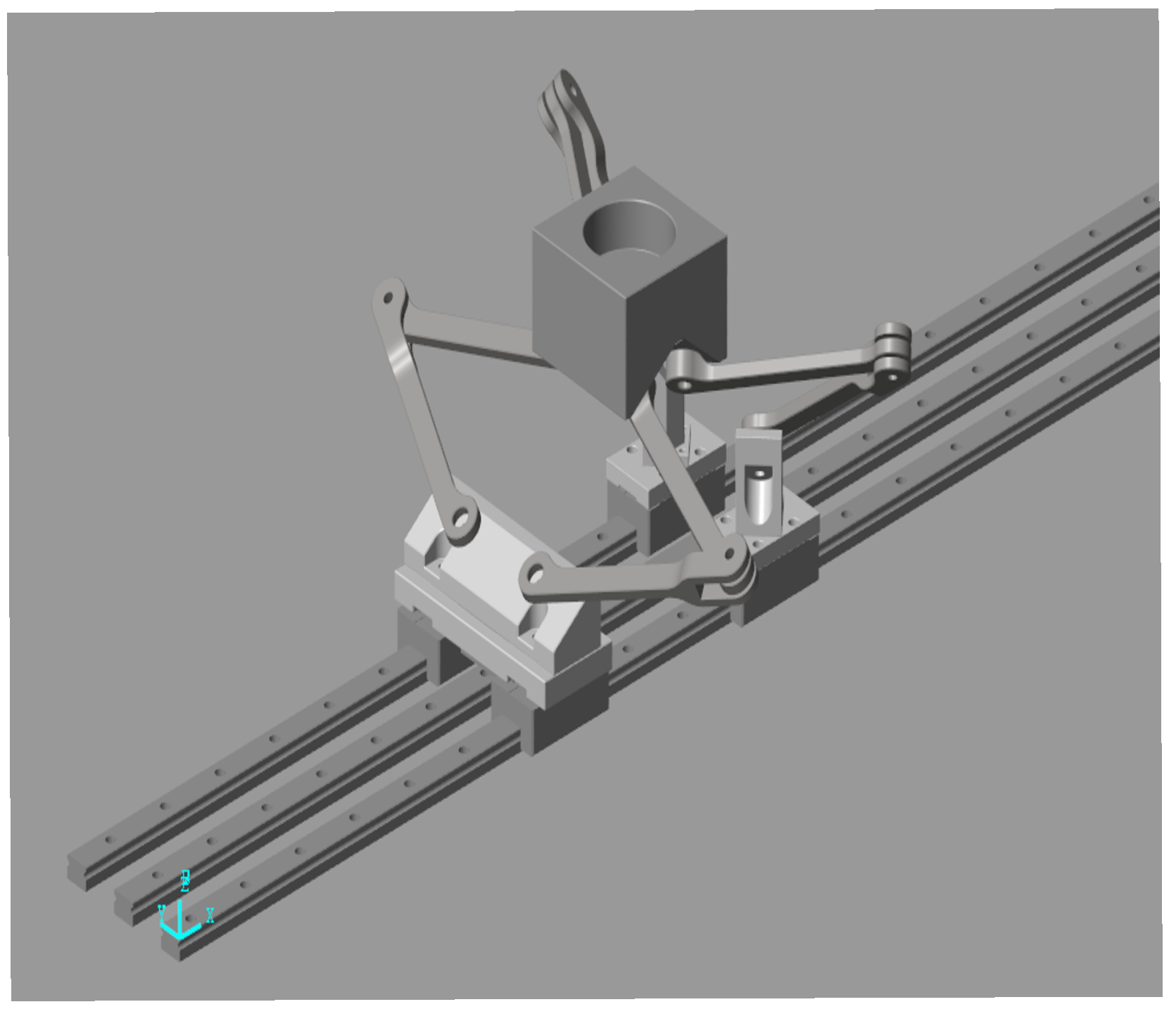
Based on the translational Tripteron principle, a three-dimensional CAD model was developed to convert the geometric constraints into a manufacturable and adjustable assembly. The design preserves the parallel nature of the three limbs while extending reach along the main direction by lengthening linear guidance. Accordingly, the three prismatic joints are placed on three parallel rails, so the stroke along the rail direction increases with rail length while the limb constraint form remains unchanged. In the assembly, one limb adopts a two-parallel-link module connected to a single prismatic joint, while the remaining two limbs use single-link configurations, and the end-effector still performs pure translation without rotation. The CAD model bridges the theoretical parameterisation and hardware selection because the joint variables are realised as linear slider displacements along the rails.
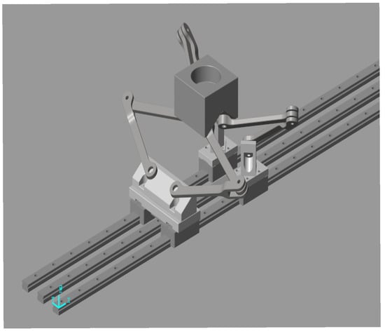
Figure 2 shows three linear guide modules mounted on an aluminium profile frame, each carrying a slider that serves as the limb attachment point. Linear guide rails of type MSB15S were selected to ensure straightness and stiffness over the long stroke and to simplify parallel alignment. Each slider is driven by an XL037 timing belt with 24-tooth driving and driven pulleys, an approximate pitch diameter of 38.81 mm, a belt width of 9.5 mm, an open-end belt length of 3323 mm, and a designed centre distance of 1600 mm. This arrangement places the motor at the rail end to reduce moving mass, while belt tensioning and intermediate pulleys maintain stable tension to reduce slip and transmission error. The linkage geometry is fixed by the parameter set to to maintain consistency between the kinematic model and the CAD assembly, as summarised in Table 1. When changing the guide type, belt type, or other linear actuation technologies, the joint attachment distances and link lengths must remain invariant because they directly determine the limb-plane equations and the forward and inverse kinematics, so the same constraint-based formulation can be reused across hardware variants.
Figure 2.
Prototype-level 3D CAD model of the rail-extended Tripteron mechanism, showing three rail-mounted prismatic sliders, passive link assemblies, and the translational end-effector platform. The long rail arrangement increases the available prismatic stroke and extends the reachable workspace mainly along the rail direction.
Table 1.
Main geometric parameters of the mechanism in the CAD assembly model (mm).
3.2. Fabricated Prototype and Experimental Measurement Results
A prototype was fabricated from the 3D model to validate the translational motion capability and quantify positioning errors. The frame was designed to be lightweight for low-payload operation while remaining sufficiently stiff for positioning tests. Linkage and mounting parts were produced to support experimental adjustments, and selected components can be fabricated by 3D printing to shorten iteration cycles when assembly errors occur. Each axis uses a step servo motor with a holding torque of 2.5 Nm and a maximum speed of 3000 rpm, an incremental encoder with 1024 lines, and an SSDC06 EC MW01 driver supporting EtherCAT as well as position, velocity, and cyclic synchronous modes. The control network employs an EtherCAT coupler EK1828 interfaced to a TwinCAT 3 control computer for multi-axis command execution and I/O acquisition during experiments.
To separate modelling error from operational error and ensure repeatability, each axis first performed homing to establish the displacement reference. The encoder count to displacement mapping was calibrated by commanding a known reference travel and computing the conversion factor from counts to millimetres. The test set covers the workspace by selecting random task-space points. For each point, the controller computed joint commands using the inverse kinematics, executed the motion, waited for settling, and recorded the measured coordinates. Each point was repeated times, and the reported are averages over the 30 repetitions. A non-contact optical sensor was used, with a reflective target rigidly mounted on the end-effector. The measurement frame was calibrated to the robot base frame, and the marker to TCP offset was compensated by a fixed design-based offset vector. The axis-wise errors are defined by
and the aggregated positional error is
Table 2 summarises the positioning results. The sample points show both positive and negative axis-wise errors, indicating deviations distributed around the commanded values rather than a consistent one-sided bias. The corresponding values for the shown samples range from 0.83 mm to 1.11 mm, and the mean over the full set of 20 points is 0.97 mm, which indicates repeatable positioning performance in the tested workspace region under the stated measurement conditions.
Table 2.
Positioning test results with random points, each measured times using a non-contact external measurement method, only 3 sample points are shown, unit mm.
4. Conclusions
This study proposed and validated a belt-driven slide-rail Tripteron-type translational parallel robot aimed at extending the reachable workspace without changing the core translational constraint structure. A plane-constraint formulation was used to derive concise kinematic relations, providing (i) an explicit inverse kinematics mapping from TCP position to prismatic displacements, (ii) a linear forward kinematics solution from plane intersection, and (iii) a closed-form differential model with a compact Jacobian representation that is convenient for real-time control and sensitivity analysis. The operational workspace was evaluated by numerical scanning under stroke limits, showing that the reach along the rail direction can be expanded by increasing rail stroke while the lateral cross-sections remain governed by limb geometry. A prototype was implemented with EtherCAT-based multi-axis control in TwinCAT 3 and executed smooth motions using LSPB trajectory planning. Experimental positioning tests using an external non-contact measurement setup confirmed repeatable translational behavior, with a mean Euclidean positioning error of mm over 20 random target points (30 repetitions each) under the reported conditions. The proposed robot can be used for low-payload translational applications that require an extended working range, such as light pick-and-place, conveyor-based sorting, sensor positioning, inspection, scanning, laboratory automation, and educational demonstrations of parallel robot kinematics. Future work will (i) perform systematic performance assessment following ISO 9283, (ii) introduce kinematic calibration and parameter identification to improve absolute accuracy, and (iii) model and compensate belt-drive compliance and vibration effects using jerk-limited trajectories and enhanced control/observer designs to further improve dynamic tracking at higher speeds and longer strokes.
Author Contributions
Conceptualization and methodology: T.D.C. and N.K.T.; Investigation and analysis: T.D.C.; Writing and draft preparation: N.K.T.; supervision: N.K.T. All authors have read and agreed to the published version of the manuscript.
Funding
This research is funded by University of Economics Ho Chi Minh City, Vietnam (UEH).
Institutional Review Board Statement
Not applicable.
Informed Consent Statement
Not applicable.
Data Availability Statement
The original contributions presented in this study are included in the article. Further inquiries can be directed to the corresponding author.
Conflicts of Interest
The authors declare no conflicts of interest.
References
- Toan, N.K.; Thinh, N.T. Integrating vision-language models for enhanced robotic grasping and interaction using RGB image and prompt. Int. J. Mech. Eng. Robot. Res. 2025, 14, 500–510. [Google Scholar] [CrossRef] [Scilit]
- Lasi, H.; Fettke, P.; Kemper, H.G.; Feld, T.; Hoffmann, M. Industry 4.0. Bus. Inf. Syst. Eng. 2014, 6, 239–242. [Google Scholar] [CrossRef] [Scilit]
- Triet, L.M.; Thinh, N.T. CFNet: Advancing automated pollination with YOLOv8-based cantaloupe floral detection. Smart Agric. Technol. 2026, 13, 101926. [Google Scholar] [CrossRef] [Scilit]
- Cao-Ky-Long, U.; Toan, N.K. Emergency UAV delivery framework: A hybrid approach to GPS navigation and visual landmark detection. Int. J. Mech. Eng. Robot. Res. 2025, 14, 374–383. [Google Scholar] [CrossRef] [Scilit]
- Triet, L.M.; Thinh, N.T. Behavior modeling and bio-hybrid systems: Using reinforcement learning to enhance cyborg cockroach in bio-inspired swarm robotics. IEEE Access 2025, 13, 100119–100148. [Google Scholar] [CrossRef] [Scilit]
- Merlet, J.-P. Parallel Robots; Springer: Dordrecht, The Netherlands, 2006. [Google Scholar]
- Kong, X.; Gosselin, C.M. Kinematics and singularity analysis of a novel type of 3-CRR 3-DOF translational parallel manipulator. Int. J. Rob. Res. 2002, 21, 791–798. [Google Scholar] [CrossRef] [Scilit]
- Gosselin, C.M.; Kong, X.; Foucault, S.; Bonev, I.A. A fully decoupled 3-DOF translational parallel mechanism. In Proceedings of the 2002 Parallel Kinematic Machines International Conference, Chemnitz, Germany, 20–21 April 2004. [Google Scholar]
- Toan, N.K.; Thuan, L.; Long, L.; Thinh, N. Development of humanoid robot head based on FACS. Int. J. Mech. Eng. Robot. Res. 2022, 11, 365–372. [Google Scholar] [CrossRef] [Scilit]
- Anvari, Z.; Ataei, P.; Tale Masouleh, M. The collision-free workspace of the Tripteron parallel robot based on a geometrical approach. In Computational Kinematics; Springer: Cham, Switzerland, 2017; pp. 357–364. [Google Scholar]
- Gosselin, C.M.; Angeles, J. Singularity analysis of closed-loop kinematic chains. IEEE Trans. Robot. Autom. 1990, 6, 281–290. [Google Scholar] [CrossRef] [Scilit]
- Yoshikawa, T. Manipulability of robotic mechanisms. Int. J. Rob. Res. 1985, 4, 3–9. [Google Scholar] [CrossRef] [Scilit]
- Arian, A.; Danaei, B.; Tale Masouleh, M. Kinematic and dynamic analyses of Tripteron, an over-constrained 3-DOF translational parallel manipulator, through Newton–Euler approach. AUT J. Model. Simul. 2018, 50, 61–70. [Google Scholar] [CrossRef] [Scilit]
- Yahyapour, I.; Hasanvand, M.; Tale Masouleh, M.; Yazdani, M.; Tavakoli, S. On the inverse dynamic problem of a 3-PRRR parallel manipulator, the Tripteron. In Proceedings of the 2013 First RSI/ISM International Conference on Robotics and Mechatronics (ICRoM), Tehran, Iran, 13–15 February 2013; pp. 390–395. [Google Scholar]
- Beiranvand, A.; Kalhor, A.; Tale Masouleh, M. Modeling, identification and minimum length integral sliding mode control of a 3-DOF Cartesian parallel robot by considering virtual flexible links. Mech. Mach. Theory 2021, 157, 104183. [Google Scholar] [CrossRef] [Scilit]
- Heydarzadeh, M.; Karbasizadeh, N.; Tale Masouleh, M.; Kalhor, A. Experimental kinematic identification and position control of a 3-DOF decoupled parallel robot. Proc. Inst. Mech. Eng. Part C J. Mech. Eng. Sci. 2019, 233, 1841–1855. [Google Scholar] [CrossRef] [Scilit]
- Minh Trieu, N.; Tan No, N.; Nguyen Vu, T.; Thinh, N.T. Chattering-free PID-nested nonsingular terminal sliding mode controller design for electrical servo drives. Mathematics 2025, 13, 1197. [Google Scholar] [CrossRef] [Scilit]
- Xie, Y.; Li, Y.; Cheung, C. Design and modeling of a novel Tripteron-inspired triaxial parallel compliant manipulator with compact structure. Micromachines 2022, 13, 678. [Google Scholar] [CrossRef] [Scilit]
- Wang, L.; Zhang, J.W.; Zhang, D. A review on reconfigurable parallel mechanisms: Design, analysis and challenge. Engineering 2025, 47, 100–116. [Google Scholar] [CrossRef] [Scilit]
- Boscariol, P.; Tamellin, I. Actuation along a single linear axis: The kinematics of the single-rail Tripteron. In Proceedings of the IFToMM Symposium on Mechanism Design for Robotics, Udine, Italy, 11–13 September 2024; pp. 73–81. [Google Scholar]
- Huang, X.; Rendon-Morales, E.; Aviles-Espinosa, R. ROMI: Design and experimental evaluation of a linear Delta robotic system for high-precision applications. Machines 2023, 11, 1072. [Google Scholar] [CrossRef] [Scilit]
- Minh, V.T.; Tamre, M.; Sekhri, L. Modeling and robust control algorithms for a linear belt-driven system. Open Comput. Sci. 2018, 8, 142–153. [Google Scholar] [CrossRef] [Scilit]
- Cena, G.; Cibrario Bertolotti, I.; Scanzio, S.; Valenzano, A.; Zunino, C. Evaluation of EtherCAT distributed clock performance. IEEE Trans. Ind. Inform. 2011, 8, 20–29. [Google Scholar] [CrossRef] [Scilit]
- Beckhoff Automation. TwinCAT 3 NC PTP, TF50x0 Manual; Beckhoff Automation GmbH & Co. KG: Verl, Germany, 2025. [Google Scholar]
- Beckhoff Automation. TwinCAT 3 PLC Manual; Beckhoff Automation GmbH & Co. KG: Verl, Germany, 2025. [Google Scholar]
- Siciliano, B.; Sciavicco, L.; Villani, L.; Oriolo, G. Robotics: Modelling, Planning and Control; Springer: London, UK, 2009. [Google Scholar]
- Corke, P. Robotics, Vision and Control: Fundamental Algorithms in Python; Springer: Cham, Switzerland, 2023. [Google Scholar]
- Li, X.; Tan, S.; Feng, X.; Rong, H. LSPB trajectory planning: Design for the modular robot arm applications. In Proceedings of the 2009 International Conference on Information Engineering and Computer Science, Wuhan, China, 19–20 December 2009; pp. 1–4. [Google Scholar]
- Macfarlane, S.; Croft, E.A. Jerk-bounded manipulator trajectory planning: Design for real-time applications. IEEE Trans. Robot. Autom. 2003, 19, 42–52. [Google Scholar] [CrossRef] [Scilit]
- Constantinescu, D.; Croft, E.A. Smooth and time-optimal trajectory planning for industrial manipulators along specified paths. J. Robot. Syst. 2000, 17, 233–249. [Google Scholar] [CrossRef] [Scilit]
- Gasparetto, A.; Zanotto, V. A new method for smooth trajectory planning of robot manipulators. Mech. Mach. Theory 2007, 42, 455–471. [Google Scholar] [CrossRef] [Scilit]
- Rymansaib, Z.; Iravani, P.; Sahinkaya, M.N. Exponential trajectory generation for point-to-point motions. In Proceedings of the 2013 IEEE/ASME international conference on advanced intelligent mechatronics, Wollongong, Australia, 9–12 July 2013; pp. 906–911. [Google Scholar]
- Gates Corporation. PowerGrip GT3 Drive Design Manual; Gates Corporation: Denver, CO, USA, 2014. [Google Scholar]
- ISO 9283:1998; Manipulating Industrial Robots—Performance Criteria and Related Test Methods. International Organization for Standardization (ISO): Geneva, Switzerland, 1998.
- Hollerbach, J.M.; Wampler, C.W. The calibration index and taxonomy for robot kinematic calibration methods. Int. J. Rob. Res. 1996, 15, 573–591. [Google Scholar] [CrossRef] [Scilit]

Disclaimer/Publisher’s Note: The statements, opinions and data contained in all publications are solely those of the individual author(s) and contributor(s) and not of MDPI and/or the editor(s). MDPI and/or the editor(s) disclaim responsibility for any injury to people or property resulting from any ideas, methods, instructions or products referred to in the content. |
© 2026 by the authors. Licensee MDPI, Basel, Switzerland. This article is an open access article distributed under the terms and conditions of the Creative Commons Attribution (CC BY) license.