


Abstract
Intelligent sensors are becoming indispensable for environmental monitoring, biosensing and human–machine interaction. Among the various device platforms, organic electrochemical transistors (OECTs) stand out for their high sensitivity, low operating voltage and excellent biocompatibility. Floating-gate OECTs (FGOECTs), an extended configuration that spatially separates the sensing and amplification functions, have been shown to further improve sensing stability and immunity to interference. However, the lack of a dedicated theoretical framework has limited the mechanistic understanding and rational optimization of these devices. Here, we present a theoretical investigation of the operating mechanism of FGOECTs and establish an analytical model describing the floating-gate coupling regulation process. The model reveals the intrinsic relationships among floating-gate potential modulation, ion–electron coupled transport and channel conductance variation. It accurately reproduces the current–voltage characteristics of FGOECTs and elucidates their signal transduction mechanism during sensing. Our work provides a theoretical foundation for the design and optimization of FGOECT-based devices and offers guidance for the development of high-performance sensors and transducers for next-generation wearable intelligent sensing.
1. Introduction
The convergence of artificial intelligence, the Internet of Things and intelligent sensing technologies has created an urgent demand for wearable sensors capable of continuous, real-time monitoring of environmental and physiological signals [1]. Among the various transduction platforms, organic electrochemical transistors (OECTs) have emerged as a leading candidate for flexible biosensing: in these devices, ions from an electrolyte penetrate the bulk of an organic mixed ionic–electronic conductor channel and modulate its doping state, a volumetric ion–electron coupling mechanism that yields transconductance values far exceeding those of conventional transistor technologies, together with low operating voltage, mechanical flexibility and intrinsic biocompatibility [2,3,4]. These attributes have enabled diverse biosensing applications, from metabolite and ion detection to electrophysiological recording [5,6,7], and have been further advanced by fabric- and textile-based OECTs [8,9], strain-insensitive stretchable devices [10], internal-ion-gated and vertical architectures [11,12,13,14], and OECTs with reconfigurable sensing, memory and processing functions [15]. Nevertheless, a persistent challenge remains: in conventional OECT configurations, the analyte, the recognition element and the channel share the same electrolyte environment, so that non-specific adsorption, parasitic electrochemical reactions and electrolyte fluctuations directly perturb channel conductance and degrade sensing stability. Floating-gate OECTs (FGOECTs) address this issue by capacitively coupling a sensing gate to the channel through a floating gate, thereby spatially separating signal acquisition from amplification; recent demonstrations, including wearable enzyme sensors [16], ion-selective sensing circuits for real-time K+ monitoring [17] and faradaic floating-gate sensors operating in complex media [18], underscore the promise of this architecture for practical wearable sensing.
A rational design of FGOECTs, however, requires quantitative theoretical models that link device geometry, material properties and operating conditions to electrical characteristics. For conventional OECTs, the seminal Bernards–Malliaras model describes the steady-state and transient response in terms of coupled ionic and electronic circuits [19], and subsequent work has refined the treatment of device physics [20], developed numerical models based on the Poisson and Nernst–Planck equations [21], and revealed the non-equilibrium distribution of ions and charges along the channel [22]. These efforts, together with systematic benchmarking of channel materials [23,24,25] and circuit-level implementations [26], have established a relatively mature theoretical framework for conventional OECTs. In contrast, no dedicated theoretical model currently exists for FGOECTs. The floating-gate coupling introduces an additional degree of freedom—the potential of a floating electrode that is set not by an external power supply but by the electrochemical equilibrium at the sensing interface—and the way in which this potential is transduced into channel conductance modulation remains poorly understood. This gap limits both the mechanistic understanding of FGOECTs and the rational optimization of their performance for wearable intelligent sensing applications.
Here, we present a theoretical investigation of the operating mechanism of FGOECTs and establish an analytical model for the floating-gate coupling regulation process. By describing how the floating-gate potential is established at the sensing interface and how it governs ion injection into the mixed-conductor channel, the model reveals the intrinsic relationships among floating-gate potential modulation, ion–electron coupled transport and channel conductance variation. We show that the model accurately reproduces the current–voltage characteristics of FGOECTs and quantitatively explains their signal transduction mechanism during sensing. Our results provide a theoretical foundation for the design and optimization of FGOECT-based devices and offer guidance for the development of high-performance sensors and transducers for next-generation wearable intelligent sensing systems.
2. Materials and Methods
2.1. Reagents
Poly(3,4-ethylenedioxythiophene)-poly(styrenesulfonate) (PEDOT:PSS), ethylene glycol (EG), dodecylbenzene sulfonic acid (DBSA), and (3-glycidyloxypropyl)trimethoxysilane (GOPS) were purchased from Shanghai Aladdin Biochemical Technology Co., Ltd. (Shanghai, China),. Iron(III) chloride (FeCl3) was obtained from Sinopharm Chemical Reagent Co., Ltd. (Shanghai, China).
2.2. Instruments
The characterization of the zinc oxide nanowires was performed using scanning electron microscopy (JSM-IT700HR, JEOL, Akishima, Japan). Electrochemical impedance spectroscopy (EIS, San Francisco, CA, USA) evaluations were carried out on an electrochemical workstation (CS2350, Corrtest, Wuhan, China). The channel current of the OECT was recorded using a source meter (Keithley 2636B, Keithley Instruments, Cleveland, OH, USA).
2.3. Device Fabrication and Structure
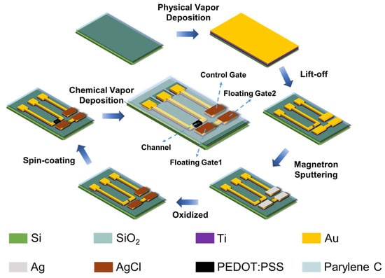
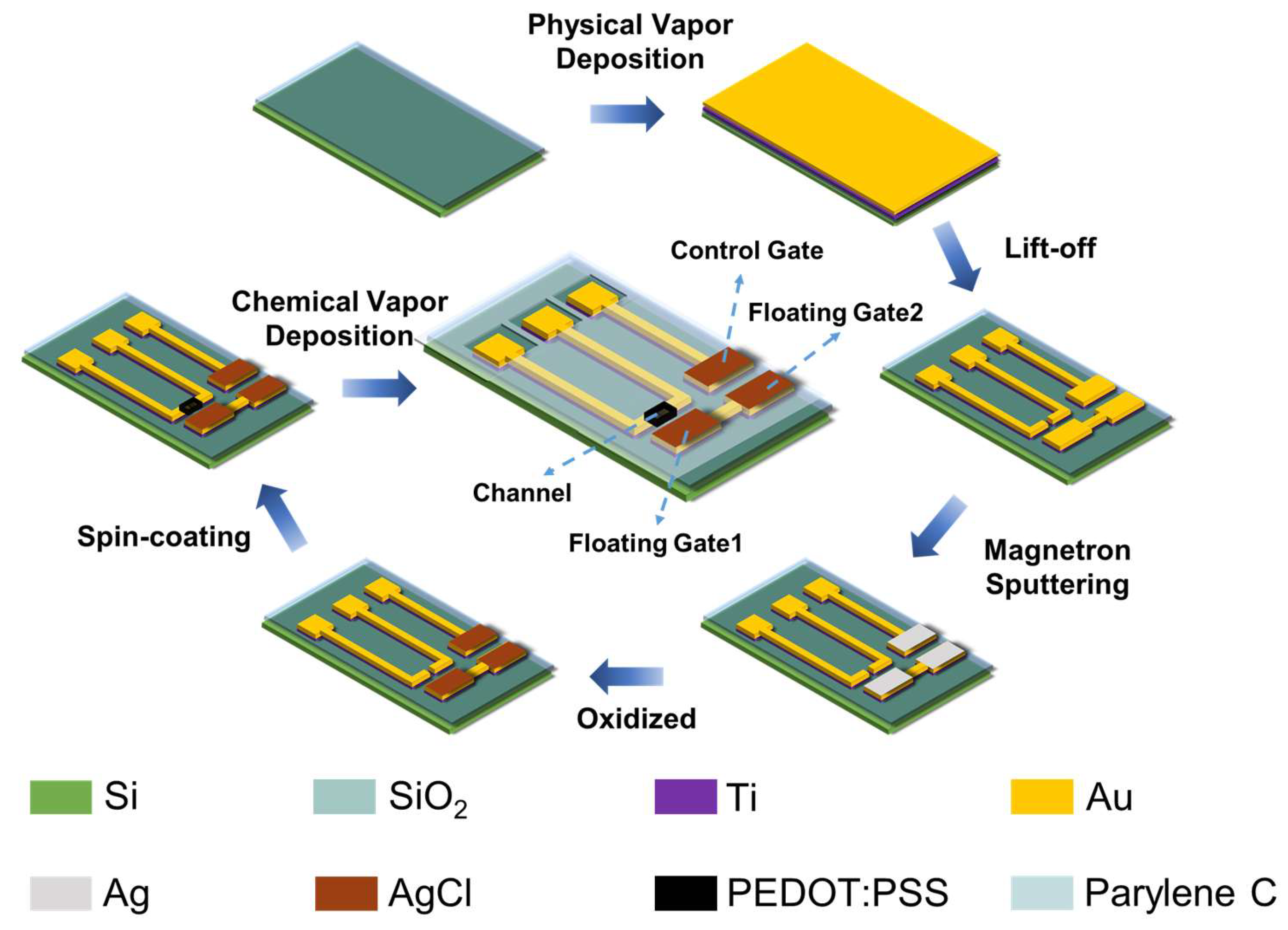
The FGOECTs were fabricated on SiO2/Si substrates through a sequence of physical vapour deposition, photolithographic patterning and solution processing steps, as schematically illustrated in Figure 1. First, a Ti/Au bilayer was deposited over the entire substrate by physical vapour deposition, and the microelectrode patterns—including the source and drain electrodes, the control gate (CG) and the two terminals of the floating gate (FG1 and FG2)—were defined by a lift-off process. Next, Ag films were selectively deposited on the CG, FG1 and FG2 electrodes by magnetron sputtering and subsequently oxidized to form AgCl layers, which provide stable and well-defined interfacial potentials at all three gate electrodes. PEDOT:PSS was then spin-coated to define the channel bridging the source and drain electrodes. Finally, a Parylene C layer was deposited by chemical vapour deposition as an encapsulation layer. The encapsulation was patterned so that the electrical contact pads and the electrolyte-access windows above the functional interfaces, including the CG/FG2 gating region, the FG1/channel amplification region and the PEDOT:PSS channel area, remained exposed to the electrolyte, whereas the metal interconnects and inactive regions were insulated. Therefore, during device operation, the electrolyte contacted only the designed Ag/AgCl gate interfaces and the PEDOT:PSS channel, while parasitic leakage through the interconnects was effectively suppressed. The resulting device consists of two functional regions connected by the floating-gate electrode: a gating region composed of the CG and FG2, and an amplification region composed of FG1 and the PEDOT:PSS channel. In this configuration, the potential of the floating gate is established by capacitive coupling across the two regions and regulates the conductance of the PEDOT:PSS channel, thereby achieving the physical separation of gating and amplification functions.
Figure 1.
Schematic illustration of the fabrication process and device architecture of the FGOECT.
3. Results and Discussion
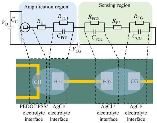
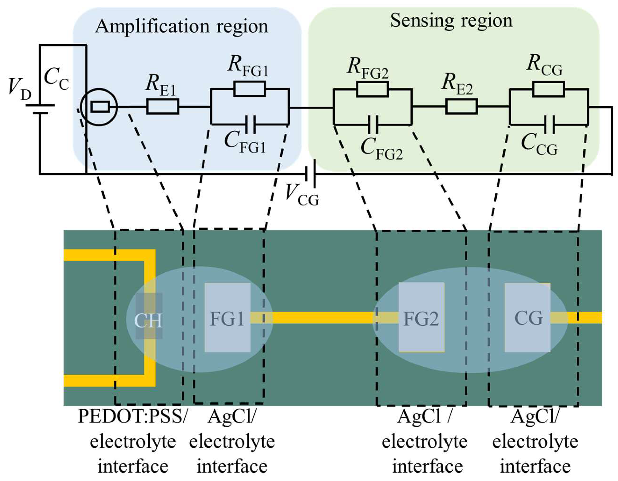
The equivalent circuit of the FGOECT is shown in Figure 2, partitioned into the amplification region (left, blue) and the gating region (right, green), with each circuit element mapped onto the corresponding physical interface of the device (lower panel). The circuit represents the complete signal path from the control-gate bias VCG to the drain current IDS. Starting from VCG, the applied bias is delivered to the control gate and crosses the AgCl/electrolyte interface, represented by the parallel combination of CCG and RCG. The secondary electrolyte contributes a series resistance RE2 and couples to FG2 through the second AgCl/electrolyte interface, represented by the parallel combination of CFG2 and RFG2. From FG2, the signal propagates through the metallic bulk of the floating gate to FG1—the only electrical connection between the two regions—and crosses the third AgCl/electrolyte interface into the primary electrolyte. The primary electrolyte contributes a series resistance RE1 and finally couples to the PEDOT:PSS channel through the channel/electrolyte capacitance CC. The channel, biased between drain and source by VD, delivers the output current IDS.
Figure 2.
Equivalent circuit model of the FGOECT, partitioned into the amplification region (left, blue) and the sensing region (right, green).
The following derivations are established upon several fundamental premises: (i) bulk electrolyte maintains electroneutrality; (ii) the gradual channel approximation governs charge transport within the organic semiconductor; (iii) bulk solution resistance remains negligible relative to interfacial impedance; (iv) carrier mobility is independent of local hole concentration; and (v) under ultraviolet irradiation, the interfacial capacitance at the electrolyte/photoactive-gate boundary does not vary with different illumination intensity.
The floating-gate node is electrically isolated, which satisfies the principle of net-charge conservation. Based on capacitive charge partitioning, the charge contributed from the control gate and channel capacitances to the floating-gate node yields:
where // denotes the parallel operation, and .
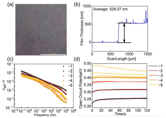
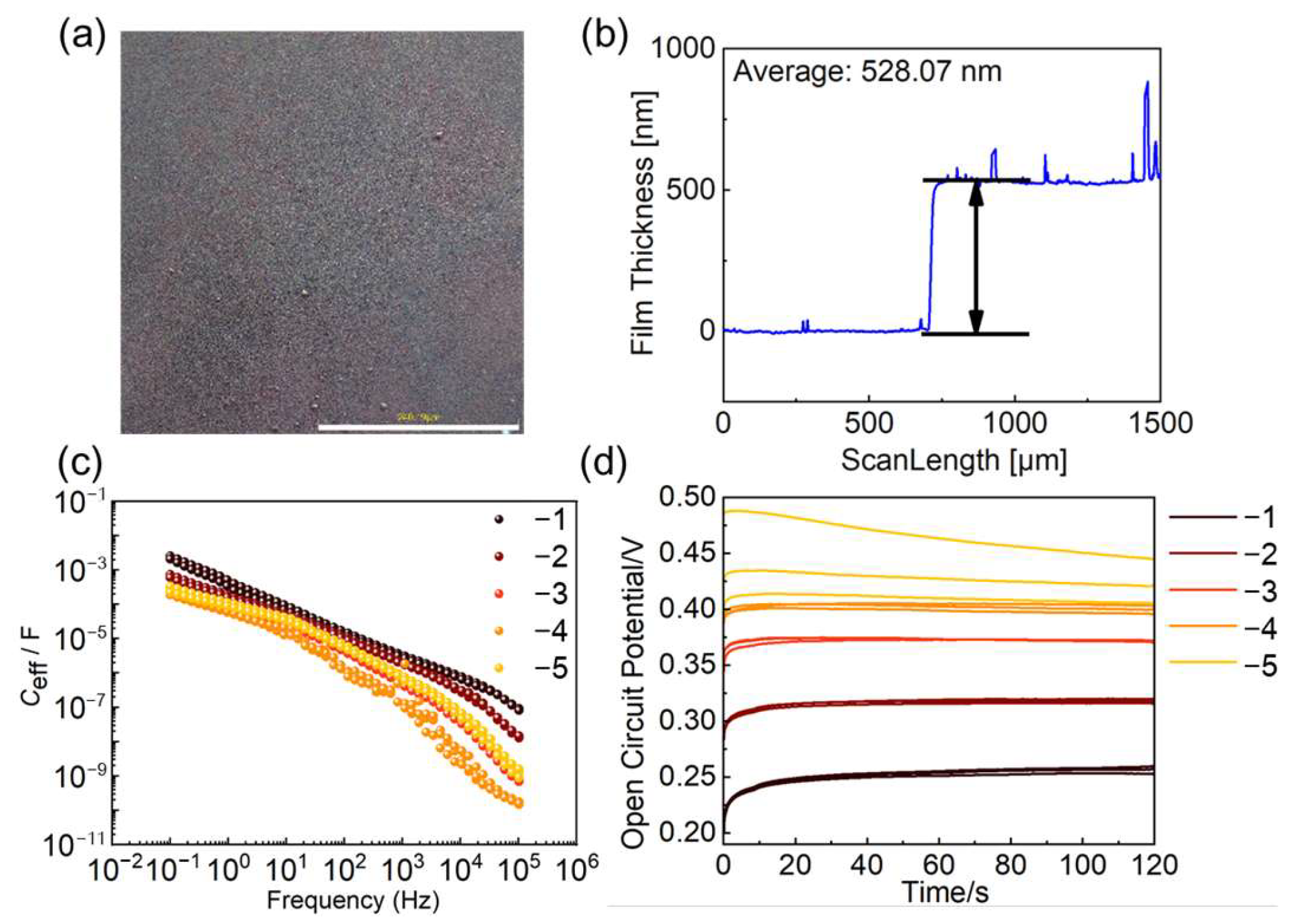
In the FGOECT architecture, the AgCl layers on the CG and FG1 electrodes are intended to serve as non-polarizable interfaces whose potential remains constant during operation, and their properties were therefore systematically characterized as a function of NaCl concentration (Figure 3). Optical microscopy reveals a continuous and uniform AgCl film covering the electrode surface over hundreds of micrometres, without observable cracks or pinholes (Figure 3a). Profilometry measurements across the film edge show a sharp, well-defined step with an average thickness of 528 nm (Figure 3b), confirming the conformal and controllable nature of the sputtering–oxidation process. The interfacial capacitance of the AgCl electrodes was evaluated by electrochemical impedance spectroscopy (EIS) in NaCl solutions with concentrations ranging from 10−1 to 10−5 M. As shown in Figure 3c, the effective capacitance (Ceff) decreases monotonically with frequency, from approximately 10−3 F at 0.1 Hz to 10−8–10−9 F at 105 Hz. For each NaCl concentration, repeated capacitance–frequency measurements showed good overlap, confirming the reproducibility of the AgCl/electrolyte interface. In the concentration range of 10−4 M and above, the curves exhibited a similar frequency-dependent trend and maintained a stable interfacial capacitance within the operating frequency range of the FGOECT, whereas a pronounced deviation was observed at 10−5 M. This indicates that the AgCl interface provides a well-defined and reproducible non-polarizable behaviour when the chloride concentration is not lower than 10−4 M. Crucially, within the operating frequency range of the FGOECT, the interfacial capacitance of the AgCl electrodes remains orders of magnitude larger than the volumetric capacitance of the PEDOT:PSS channel. Open-circuit potential (OCP) measurements further confirm the stability of the interface (Figure 3d). The steady-state OCP decreases systematically with increasing NaCl concentration, consistent with the Nernstian behaviour of the Ag/AgCl redox couple, and at concentrations of 10−4 M and above the potential stabilizes within approximately 20 s and remains essentially constant, with negligible drift over 120 s. In contrast, at 10−5 M a pronounced potential drift is observed, reflecting the loss of a well-defined chloride activity at the interface. These results establish that the AgCl electrodes behave as stable, non-polarizable interfaces for NaCl concentrations of 10−4 M and above, a range that covers most physiological and environmental sensing scenarios. Owing to their exceptionally large interfacial capacitance, the AgCl/electrolyte interfaces sustain only a negligible fraction of any applied or induced voltage—voltage division occurs almost entirely across the channel and the sensing interface—so the potential drop across the AgCl layers can be ignored. The AgCl electrodes can therefore be treated as ideal, non-polarizable equipotential terminals in the floating-gate coupling model developed below, which substantially simplifies the theoretical description of the FGOECT without loss of accuracy.
Figure 3.
Characterization of the AgCl non-polarizable electrodes. (a) Optical microscopy image of the AgCl film formed on the Au electrode. Scale bar, 200 μm. (b) Film thickness profile measured across the edge of the AgCl film, showing an average thickness of 528.07 nm. (c) Frequency dependence of the effective interfacial capacitance of the AgCl electrode extracted from EIS measurements in NaCl solutions of varying concentration (10−1–10−5 M). The interfacial capacitance is stable at concentrations of 10−4 M and above, and remains orders of magnitude larger than the channel capacitance within the device operating range. (d) Open-circuit potential of the AgCl electrode as a function of time at different NaCl concentrations (10−1–10−5 M). The potential is stable for concentrations of 10−4 M and above, whereas pronounced drift is observed at 10−5 M. The numbers −1, −2, −3, −4 and −5 in the legend denote the exponent of the NaCl concentration, corresponding to 10−1, 10−2, 10−3, 10−4 and 10−5 M, respectively.
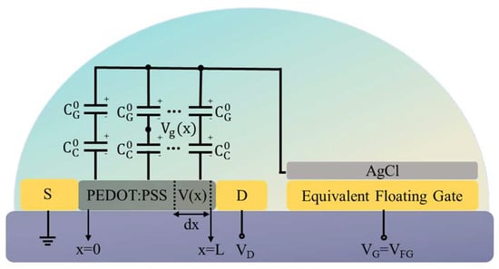
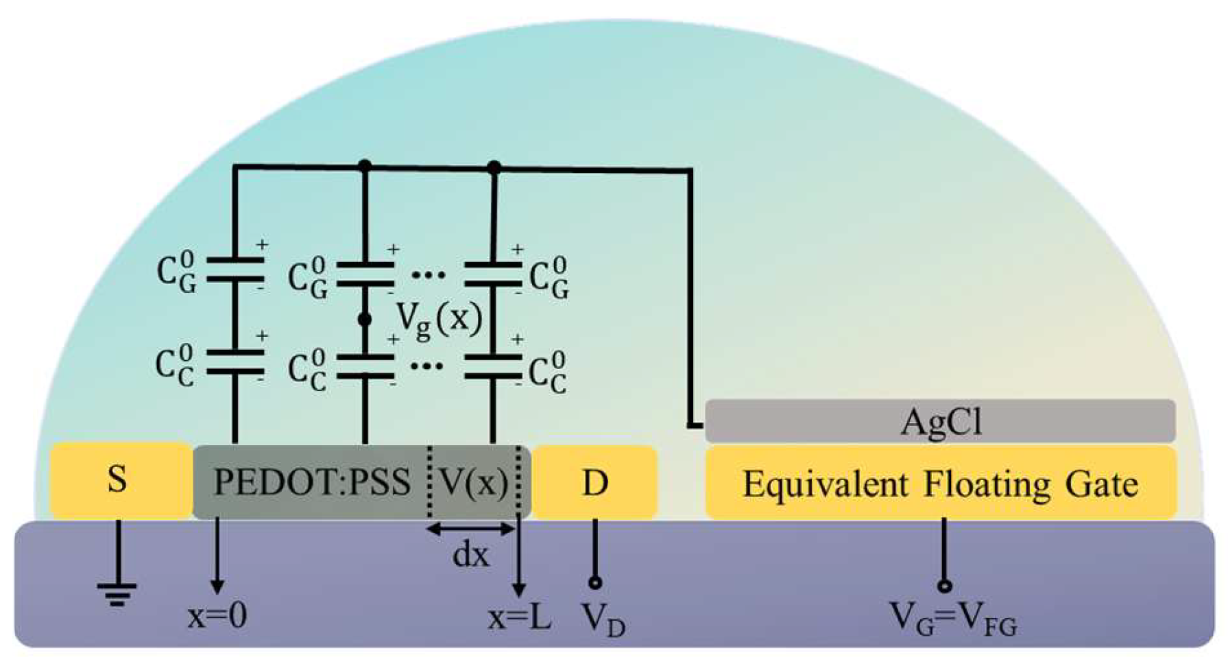
The simplified model diagram is shown in Figure 4. From this, Formula 1 can be evolved into:
where VG denotes the floating-gate potential VFG, and CG represents the total capacitance of the floating gate, which is the parallel combination of CFG1, CFG2 and CG, V(x) is the local electric potential within the semiconductor at coordinate x, and Ctot = CC + CG represents the total interfacial capacitance. denotes the solution potential, and represents the differential interfacial capacitance.
Figure 4.
Reduced-dimensional equivalent model of the FGOECT.
The drift current density within the organic semiconductor follows:
where μ is hole mobility and p(x) denotes the local hole density. Ion injection from the electrolyte modulates the carrier population according to:
with p0 being the intrinsic hole density and W and H representing the channel width and thickness, respectively. The injected charge QC relates to the potential difference across the channel/electrolyte interface:
where is the volumetric capacitance of the semiconducting film.
Combining Equations (3)–(5) yields:
Substituting Equation (2) into Equation (6) and integrating from source (x = 0, V = 0) to drain (x = L, V = VD):
After algebraic manipulation, the drain–source current in the linear regime is obtained:
where represents the channel conductance in the absence of gating.
Channel pinch-off occurs at the drain terminal when:
which, combined with Equation (2), gives the pinch-off condition:
Solving for the drain voltage at saturation:
Substituting back into Equation (8), the saturated drain current becomes:
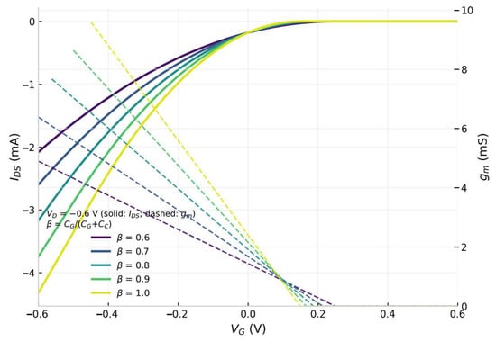
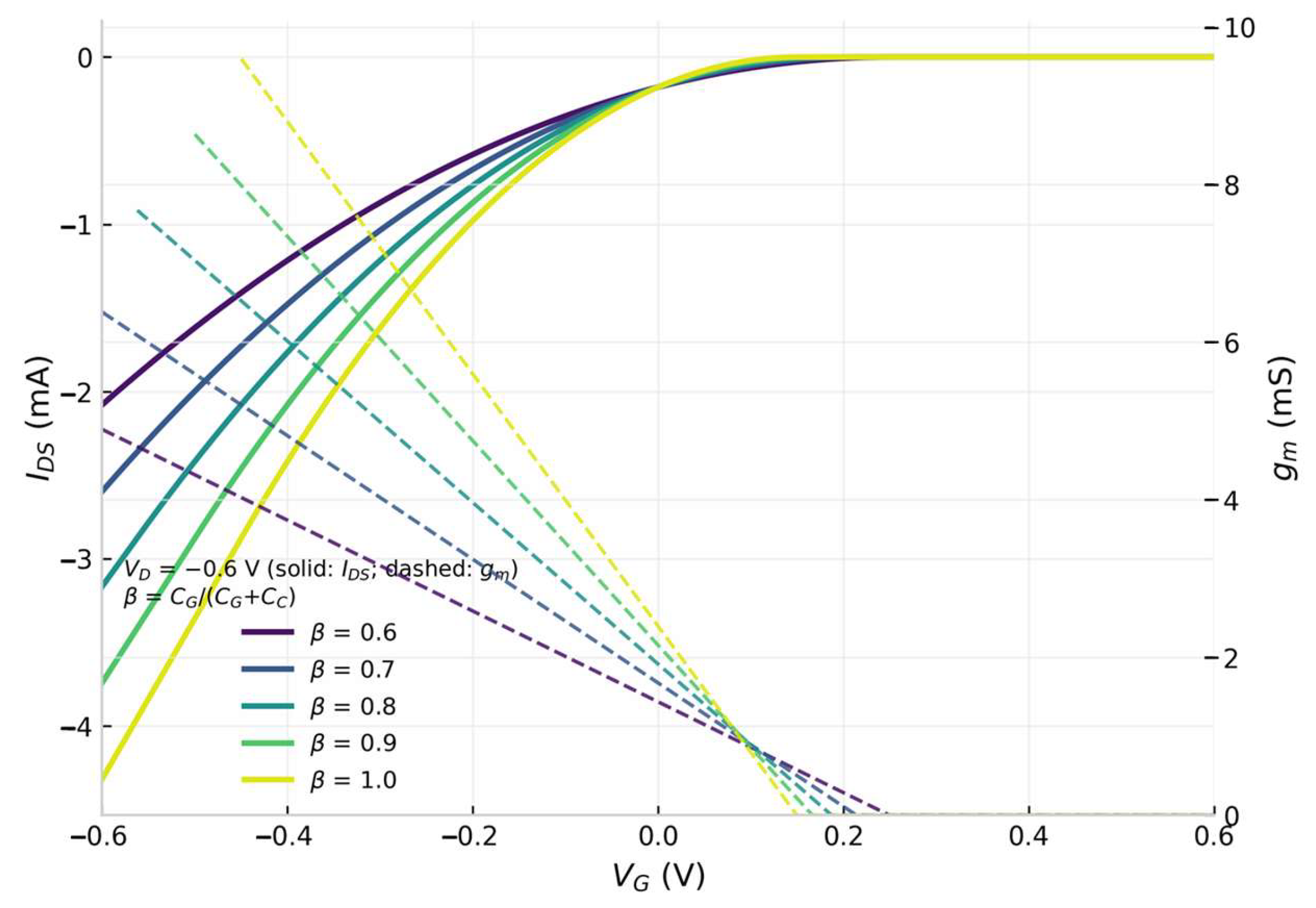
To validate the analytical model and visualize the floating-gate coupling regulation process, the electrical characteristics of the FGOECT were simulated using Equations (7)–(12) with experimentally informed parameters (W/L = 8, μC* = 2 mF V−1 s−1 and VT = +0.15 V). Figure 5 shows the predicted transfer characteristics at VD = −0.6 V, the operating condition employed throughout this work, for capacitive divider factors β = CG/(CG + CC) ranging from 0.6 to 1.0, together with the corresponding transconductance curves. The device exhibits typical depletion-mode behaviour, with the channel fully conducting at negative gate voltages and gradually turning off as VG approaches the threshold voltage, in agreement with the measured characteristics of the fabricated devices. More importantly, the simulation quantitatively demonstrates the regulation effect of floating-gate coupling: as the coupling factor increases from 0.6 to 1.0, the transfer characteristics become progressively steeper and the transconductance increases monotonically, because a larger fraction of the applied gate voltage is dropped across the channel/electrolyte interface rather than the gate/electrolyte interface. In the limit of a dominant gate capacitance (β → 1), the gating efficiency approaches that of an ideal single-gate OECT. These results establish the capacitive divider factor as the central design parameter of FGOECTs, and provide quantitative guidance for optimizing the gate and channel geometries to maximize device performance.
Figure 5.
Model-predicted transfer characteristics of the FGOECT at VD =−0.6 V.
In this context, the modeling framework presented here is positioned primarily as a theoretical construct to delineate the underlying device physics of FGOECTs, rather than a quantitatively calibrated description of a specific fabricated device. The model-predicted transfer characteristics shown in Figure 5 aim to reveal the intrinsic operating mechanism, qualitative evolution trends, and scaling behaviors of the device, which provide systematic physical insights and a predictive guideline for the rational design of subsequent experiments.
4. Conclusions
In this work, we established an analytical model for floating-gate organic electrochemical transistors that clarifies the floating-gate coupling regulation process. By analysing the capacitive voltage-divider network along the signal path, we showed that the high-capacitance AgCl interfaces at the control gate and the floating gate act as ideal equipotential terminals and can be excluded from voltage division, reducing the device to an effective single-gate OECT. The model reveals the intrinsic relationships among floating-gate potential modulation, ion–electron coupled transport and channel conductance variation, yielding closed-form expressions for the drain current and transconductance in both the linear and saturation regimes, which are confirmed by simulation. This work provides a theoretical foundation and quantitative design rules for the modeling, optimization and further applications of FGOECTs.
Author Contributions
F.Z. conceived the theoretical framework, developed the analytical model of the floating-gate coupling process, performed the numerical calculations and wrote the original draft of the manuscript. J.J. carried out the device fabrication and electrical measurements, validated the model against experimental data and analysed the results. S.S. supervised the project, acquired funding and revised the manuscript. All authors have read and agreed to the published version of the manuscript.
Funding
This research received no external funding.
Data Availability Statement
The raw data supporting the conclusions of this article will be made available by the authors on request.
Conflicts of Interest
The authors declare no conflicts of interest.
References
- Rivnay, J.; Inal, S.; Salleo, A.; Owens, R.M.; Berggren, M.; Malliaras, G.G. Organic electrochemical transistors. Nat. Rev. Mater. 2018, 3, 17086. [Google Scholar] [CrossRef] [Scilit]
- Berggren, M.; Malliaras, G.G. How conducting polymer electrodes operate. Science 2019, 364, 233–234. [Google Scholar] [CrossRef] [Scilit]
- Paulsen, B.D.; Tybrandt, K.; Stavrinidou, E.; Rivnay, J. Organic mixed ionic–electronic conductors. Nat. Mater. 2020, 19, 13–26. [Google Scholar] [CrossRef] [Scilit]
- Khodagholy, D.; Rivnay, J.; Sessolo, M.; Gurfinkel, M.; Leleux, P.; Jimison, L.H.; Stavrinidou, E.; Herve, T.; Sanaur, S.; Owens, R.M.; et al. High transconductance organic electrochemical transistors. Nat. Commun. 2013, 4, 2133. [Google Scholar] [CrossRef] [Scilit]
- Lin, P.; Yan, F.; Chan, H.L.W. Ion-sensitive properties of organic electrochemical transistors. ACS Appl. Mater. Interfaces 2010, 2, 1637–1641. [Google Scholar] [CrossRef] [Scilit]
- Marks, A.; Griggs, S.; Gasparini, N.; Moser, M. Organic electrochemical transistors: An emerging technology for biosensing. Adv. Mater. Interfaces 2022, 9, 2102039. [Google Scholar] [CrossRef] [Scilit]
- Song, J.; Liu, H.; Zhao, Z.; Lin, P.; Yan, F. Flexible organic transistors for biosensing: Devices and applications. Adv. Mater. 2024, 36, 2300034. [Google Scholar] [CrossRef] [Scilit]
- Gualandi, I.; Marzocchi, M.; Achilli, A.; Cavedale, D.; Bonfiglio, A.; Fraboni, B. Textile organic electrochemical transistors as a platform for wearable biosensors. Sci. Rep. 2016, 6, 33637. [Google Scholar] [CrossRef] [Scilit]
- Yang, A.; Li, Y.; Yang, C.; Fu, Y.; Wang, N.; Li, L.; Yan, F. Fabric organic electrochemical transistors for biosensors. Adv. Mater. 2018, 30, 1800051. [Google Scholar] [CrossRef] [Scilit]
- Chen, J.; Huang, W.; Zheng, D.; Xie, Z.; Zhuang, X.; Zhao, D.; Chen, Y.; Su, N.; Chen, H.; Pankow, R.M.; et al. Highly stretchable organic electrochemical transistors with strain-resistant performance. Nat. Mater. 2022, 21, 564–571. [Google Scholar] [CrossRef] [Scilit]
- Spyropoulos, G.D.; Gelinas, J.N.; Khodagholy, D. Internal ion-gated organic electrochemical transistor: A building block for integrated bioelectronics. Sci. Adv. 2019, 5, eaau7378. [Google Scholar] [CrossRef] [Scilit]
- Spyropoulos, G.D.; Gelinas, J.N.; Khodagholy, D. Integrated internal ion-gated organic electrochemical transistors for stand-alone conformable bioelectronics. Nat. Mater. 2023, 22, 1227–1235. [Google Scholar] [CrossRef] [Scilit]
- Huang, W.; Chen, J.; Yao, Y.; Zheng, D.; Ji, X.; Feng, L.-W.; Moore, D.; Glavin, N.R.; Xie, M.; Chen, Y.; et al. Vertical organic electrochemical transistors for complementary circuits. Nature 2023, 613, 496–502. [Google Scholar] [CrossRef] [Scilit]
- Kim, J.; Pankow, R.M.; Cho, Y.; Duplessis, I.D.; Qin, F.; Meli, D.; Daso, R.; Zheng, D.; Huang, W.; Rivnay, J.; et al. Monolithically integrated high-density vertical organic electrochemical transistor arrays and complementary circuits. Nat. Electron. 2024, 7, 234–243. [Google Scholar] [CrossRef] [Scilit]
- Wang, S.; Chen, X.; Zhao, C.; Kong, Y.; Lin, B.; Wu, Y.; Bi, Z.; Xuan, Z.; Li, T.; Li, Y.; et al. An organic electrochemical transistor for multi-modal sensing, memory and processing. Nat. Electron. 2023, 6, 281–291. [Google Scholar] [CrossRef] [Scilit]
- Ji, J.; Xiao, J.; Zhang, F.; Wang, Z.; Zhou, T.; Niu, X.; Zhang, W.; Sang, S.; Chai, X.; Yan, S. A wearable enzyme sensor enabled by the floating-gate OECT with poly(benzimidazobenzophenanthroline) as the catalytic layer. J. Nanobiotechnol. 2025, 23, 120. [Google Scholar] [CrossRef] [Scilit]
- Frusconi, G.; Kovács-Vajna, Z.M.; Torricelli, F. Selective and real-time ion monitoring with integrated floating-gate organic electrochemical transistor sensing circuits. Adv. Mater. Technol. 2024, 9, 2400301. [Google Scholar] [CrossRef] [Scilit]
- Yu, S.; Harris, J.K.; Ratcliff, E.L. Introducing interface redox processes in faradaic floating gate organic electrochemical sensors to improve sensor function in complex environments. ACS Appl. Electron. Mater. 2024, 6, 3127–3138. [Google Scholar] [CrossRef] [Scilit]
- Bernards, D.A.; Malliaras, G.G. Steady-state and transient behavior of organic electrochemical transistors. Adv. Funct. Mater. 2007, 17, 3538–3544. [Google Scholar] [CrossRef] [Scilit]
- Friedlein, J.T.; McLeod, R.R.; Rivnay, J. Device physics of organic electrochemical transistors. Org. Electron. 2018, 63, 398–414. [Google Scholar] [CrossRef] [Scilit]
- Shirinskaya, A.; Horowitz, G.; Rivnay, J.; Malliaras, G.G.; Bonnassieux, Y. Numerical modeling of an organic electrochemical transistor. Biosensors 2018, 8, 103. [Google Scholar] [CrossRef] [Scilit]
- Kaphle, V.; Paudel, P.R.; Dahal, D.; Krishnan, R.K.R.; Lüssem, B. Finding the equilibrium of organic electrochemical transistors. Nat. Commun. 2020, 11, 2072. [Google Scholar] [CrossRef] [Scilit]
- Inal, S.; Malliaras, G.G.; Rivnay, J. Benchmarking organic mixed conductors for transistors. Nat. Commun. 2017, 8, 1767. [Google Scholar] [CrossRef] [Scilit]
- Kukhta, N.A.; Marks, A.; Luscombe, C.K. Molecular design strategies toward improvement of charge injection and ionic conduction in organic mixed ionic–electronic conductors for organic electrochemical transistors. Chem. Rev. 2022, 122, 4325–4355. [Google Scholar] [CrossRef] [Scilit]
- Ohayon, D.; Druet, V.; Inal, S. A guide for the characterization of organic electrochemical transistors and channel materials. Chem. Soc. Rev. 2023, 52, 1001–1023. [Google Scholar] [CrossRef] [Scilit]
- Romele, P.; Gkoupidenis, P.; Koutsouras, D.A.; Lieberth, K.; Kovács-Vajna, Z.M.; Blom, P.W.M.; Torricelli, F. Multiscale real time and high sensitivity ion detection with complementary organic electrochemical transistors amplifier. Nat. Commun. 2020, 11, 3743. [Google Scholar] [CrossRef] [Scilit]
Disclaimer/Publisher’s Note: The statements, opinions and data contained in all publications are solely those of the individual author(s) and contributor(s) and not of MDPI and/or the editor(s). MDPI and/or the editor(s) disclaim responsibility for any injury to people or property resulting from any ideas, methods, instructions or products referred to in the content. |
© 2026 by the authors. Licensee MDPI, Basel, Switzerland. This article is an open access article distributed under the terms and conditions of the Creative Commons Attribution (CC BY) license.