


Abstract
In the intelligent assembly of prefabricated concrete column joints based on a multimodal transformer and digital twin, a finite element model is constructed using a digital twin to map physical entities from multiple dimensions, accurately set the material constitutive model, and rationally divide the mesh. An assembly feature integration based on multimodal transformer is proposed to achieve multimodal collaborative optimization. Two connection methods are set: integrated concrete columns with irregularly shaped composite beams and modular concrete columns with separately combined composite beams. The example results show that in the stress monitoring, the stress in the contact area between the connecting steel plate and concrete is 11.8–13.5 mpa, with uniform distribution; the stress around the bolt holes was 17.5–19.2 MPa, within a controllable range. Three-dimensional laser scanning showed that the actual and design coordinates of each component deviated very little, with the maximum deviation of the concrete column being 0.3 mm, meeting the stringent requirements of actual engineering for assembly accuracy and reliability.
1. Introduction
In the field of building engineering, prefabricated concrete column joints are key parts, and the assembly quality and performance affect the stability, safety, and durability of the entire structure. However, traditional assembly methods have limitations such as difficulty in ensuring assembly accuracy, reliance on manual experience, and lack of real-time monitoring and feedback, which restrict large-scale promotion [1,2,3]. Therefore, it is necessary to explore efficient, precise, and intelligent assembly technologies.
Therefore, this paper proposes an intelligent assembly method for prefabricated concrete column joints based on multimodal transformer and digital twin. This method utilizes a multimodal transformer to fuse and analyze various data from the assembly process, and uses a digital twin to construct a virtual assembly model to achieve real-time mapping and dynamic optimization, providing a new solution for high-quality assembly.
2. Intelligent Assembly Design of Prefabricated Concrete Column Nodes Based on Multimodal Transformer and Digital Twin
2.1. Constructing a Finite Element Model of Prefabricated Concrete Column Joints Based on Digital Twins
This paper relies on professional software to carry out the construction of its digital twin finite element model. Concrete, connecting end plates, stiffeners, and other materials have regular shapes and thicknesses [4,5]. Using three-dimensional solid elements, a precise two-dimensional diagram is first drawn and then stretched into a three-dimensional solid. Longitudinal load-bearing steel bars, transverse stirrups, and anchoring steel bars are slender and mainly subjected to axial forces [6,7]. Three dimensional truss elements are selected, and a plan view is drawn on the component interface. The software automatically generates a three-dimensional truss model.
Based on the concept of digital twin, the finite element model is deepened and expanded, and a comprehensive model architecture covering five dimensions including “physical entity, virtual entity, twin data, service, and link” is proposed. Among them, the virtual entity (VE) constructed based on the physical entity (PE) is composed of a geometric model (G), physical model (P), behavioral model (B), and rule model (R) [8]. These four models comprehensively map the physical entity from different dimensions, and their mapping relationship can be expressed by the following formula:
where is the digital twin function, , , , are the weight coefficients of each model in the virtual entity construction, and .
In the selection of material constitutive models, in order to ensure the reliability of finite element analysis results, different material properties must be accurately set. Concrete adopts a specific constitutive relation based on specifications and engineering experience; steel uses an ideal elastoplastic model, with its stress–strain relationship set according to the corresponding conditions:
where represents stress, represents elastic modulus, and represents strain. Once the stress reaches the yield strength, the stress remains constant, while the strain continues to increase.
When meshing, a strategy is selected based on the geometry and stress characteristics of each component. Components with regular shapes and uniform stress use larger mesh sizes to improve computational efficiency; complex stress areas and stress concentration regions [9] use smaller mesh sizes to ensure accuracy. Reasonable meshing lays a solid foundation for subsequent assembly.
2.2. Integrating Prefabricated Concrete Column Node Assembly Features Using Multimodal Transformer
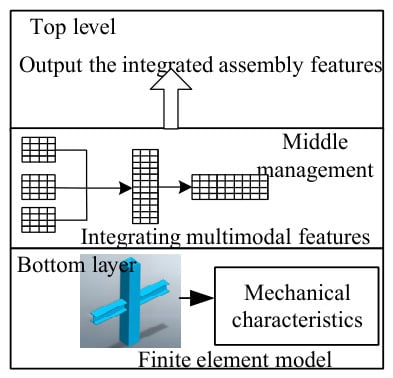
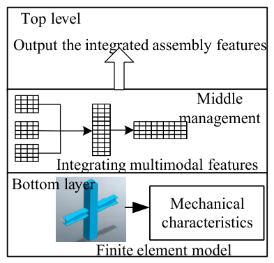
This chapter proposes a feature integration method (MT-JAM) for prefabricated concrete column node assembly based on the multimodal transformer structure. On the basis of the existing finite element model, an innovative feature extraction and integration architecture is designed to construct a transformer integration architecture that integrates multimodal information. MT-JAM introduces a multimodal transformer module parallel to the finite element feature extraction module, combining structural mechanical features with multimodal information [10]. The overall architecture of MT-JAM is illustrated in Figure 1, with a layered progression: the bottom layer obtains mechanical features, the middle layer integrates multimodal features, and the top layer outputs the integrated assembly features.
Figure 1.
Overall architecture of MT-JAM.
To enhance the ability of the multimodal transformer to capture assembly features, a unique feature weight adjustment mechanism was designed. A specific weight calculation function was designed to dynamically adjust the self-attention calculation weights based on the impact of different modal features on assembly performance.
Given the finite element mechanical eigenvector as , the geometric eigenvector as , and the material eigenvector as , the comprehensive eigenvector is calculated as:
where , , are the weight coefficient of each modal feature, and its value is determined by the following formula:
where is the base of the natural logarithm, is a parameter related to the importance of each modal feature.
This integration method breaks through the limitation of traditional single modal feature, realizes multimodal collaborative optimization, improves the reliability and stability of node assembly, and provides a comprehensive and accurate basis for subsequent performance evaluation and optimization design.
3. Examples
3.1. Example Preparation
The experiment was conducted using Visual Studio Code (1.60.0) as the development environment, Python 3.9 as the programming language, and the PyTorch 1.9.1 framework as the foundation. Model training and testing were performed using NVIDIA RTX 3090 graphics cards (NVIDIA, Santa Clara, CA, USA) at the university’s high-performance computing center. The dataset used in the experiment is as follows: Dataset A contains 2000 groups of mechanical property test data, covering different section sizes, reinforcement forms and loading conditions; Dataset B includes node geometry information, material properties and construction deviation records, with a total of 1500 node instances; Dataset C simulates a variety of boundary conditions and damage scenarios, with a scale of 3000 groups of samples. The large complex dataset includes the first three, a total of 8000 groups of samples, with additional multi-sensor monitoring data and environmental variables in the actual project. The multimodal transformer model was trained for 600 cycles on three datasets, and 250 cycles on large and complex datasets. Adamw optimizer was used with momentum coefficients of 0.92 and 0.998. The batch data size is set to 2, the initial learning rate is 0.00008, the learning rate is attenuated by 12% every 60 cycles, and the transformer branch dropout is set to 25% to prevent over fitting.
A 700 mm × 1000 mm × 1500 mm base was installed at the bottom of the column for stable connection to the testing machine platform. C25 commercial concrete was used for pouring, with 14 longitudinal reinforcing bars of diameter 18 mm and Φ10@120 stirrups. The stirrup spacing in the column base reinforcement zone was 60 mm, and the height was 600 mm. Q355 steel plates were selected, and the connection was made using CO2 gas shielded welding with ER50-6 welding wire.
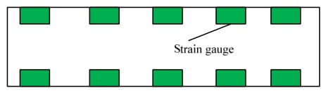
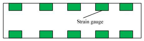
Concrete strain gauges should be placed in the middle of the post-cast concrete on the outer side of the pier column, and the strain gauges should span the joints between the post-cast concrete and the pre-cast pier column, and between the post-cast concrete and the cast-in-place pier cap. Ten concrete strain gauges should be installed on each pier column. The monitoring location on the concrete surface is shown in Figure 2. The strain gauge used is model BMB150-12AA.
Figure 2.
Monitoring locations on concrete surface.
This experiment used LD-300 (range ±150 mm), LD-150 (range ±75 mm), and LD-80 (range ±40 mm) wire-type displacement gauges to automatically collect and record displacement data. Three horizontal displacement gauges were installed at the top of the column loading head, and three at the bottom of the column. One displacement gauge was placed at the bottom of the column, at the first and second column heights, and at the third and fourth column heights to detect whether horizontal slippage occurred in the steel and concrete sections.
3.2. Example Result Analysis
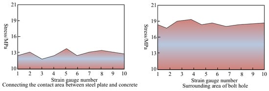
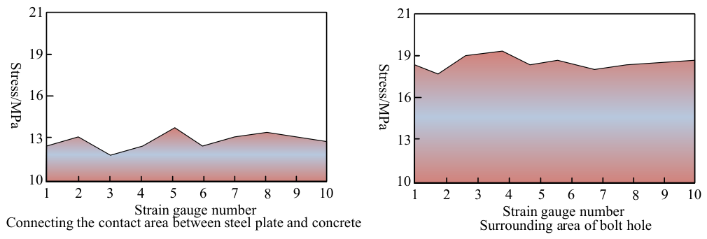
As a key connector in the intelligent assembly of prefabricated concrete column nodes, the connecting steel plate is used to investigate its stress performance during assembly by analyzing stress monitoring data of the contact area between the connecting steel plate and the concrete and the area around the bolt holes. The stress data is shown in Figure 3.
Figure 3.
Stress data during assembly.
As shown in Figure 3, the stress in the contact area between the connecting steel plate and the concrete is 11.8–13.5 MPa, and the data of each strain gauge does not fluctuate much. The stress in the area around the bolt holes is 17.5–19.2 MPa, which is higher than that in the contact area, but still within the reasonable stress range of the material. This demonstrates that intelligent assembly precisely controls bolt connections, ensuring manageable stress under load and preventing connection failure due to excessive stress.
Next, a 3D laser scanner is used to scan and measure the nodes after assembly to obtain the actual coordinate data of each component. The actual coordinates are compared with the design coordinates, and the results are shown in Table 1.
Table 1.
Comparison results of actual coordinates and design coordinates of each component.
Analysis of Table 1 reveals that the deviations in the X, Y, and Z directions of the concrete columns are only 0.2 mm, 0.1 mm, and 0.3 mm, respectively. The deviations of the rebar sleeves and embedded parts are reasonable, meeting the accuracy requirements for subsequent installation and connection.
4. Conclusions
Under the development of intelligent prefabricated buildings, the intelligent assembly technology of concrete column nodes based on multimodal transformer, and digital twins, the integration solves the problems of difficult control of traditional assembly accuracy and weak quality traceability; it is also able to monitor key parameters in real time and dynamically optimize assembly and warn risks.
Author Contributions
T.L.: Conceptualization, Data curation, Formal analysis, Investigation, Methodology, Writing—original draft, Visualization. B.L.: Investigation, Methodology, Validation, Writing—review & editing, Software, Formal analysis. X.W.: Supervision, Project administration, Writing—review & editing, Resources, Conceptualization, Validation. M.L.: Software, Data cura-tion, Formal analysis, Writing—review & editing. Y.L.: Validation, Investigation, Visualization. J.L.: Resources, Writing—review & editing. All authors have read and agreed to the published version of the manuscript.
Funding
This research received no external funding.
Institutional Review Board Statement
Not applicable.
Informed Consent Statement
Not applicable.
Data Availability Statement
The original contributions presented in this study are included in the article. Further inquiries can be directed to the corresponding author.
Conflicts of Interest
Authors Tingting Liu, Baocheng Liu, Xiaoxiang Wan, Mingqiang Li, Yangguang Li and Jinlei Liu were employed by the company Jinan Transportation Development Investment Co., Ltd. The authors declare that the research was conducted in the absence of any commercial or financial relationships that could be construed as a potential conflict of interest.
References
- Fang, M.; Xiang, L.; Wang, Y.; Li, S.; Wang, H.; Xie, H. Discretization and assembly connection technology of cement concrete pavement structure: A review. J. Road Eng. 2025, 5, 378–393. [Google Scholar] [CrossRef] [Scilit]
- Sun, R.; Fang, Q.; Zhang, H.; Jiang, Y.; Ma, K.; Wei, M.; Wu, S. Experimental and Numerical Investigation of The Assembled Monolithic Spherical-Shaped Reinforced Concrete Ribbed Folded Plate Structure. Front. Struct. Civ. Eng. 2025, 19, 300–317. [Google Scholar] [CrossRef] [Scilit]
- Liu, Y.; Yu, W.; Lin, Q.; Wang, W.; Ge, E.; Su, A.; Zhao, Y. TF-F-GAN: A GAN-based model to predict the assembly physical fields under multi-modal variables fusion on vision transformer. Adv. Eng. Inform. 2024, 62, 102871.1–102871.25. [Google Scholar] [CrossRef] [Scilit]
- Huang, C.; Lin, C.-H.; Lee, S. Rapid recognition and localization of virtual assembly components in bridge 3D point clouds based on supervoxel clustering and transformer. Int. J. Simul. Multidiscip. Des. Optim. 2025, 16, 24. [Google Scholar] [CrossRef] [Scilit]
- Takatori, N.; Ogura, D.; Wakiya, S. Simultaneous heat, moisture, and salt transfer in porous building materials considering osmosis flow: Part 1: Theoretical modeling based on nonequilibrium thermodynamics. J. Build. Phys. 2024, 48, 129–167. [Google Scholar] [CrossRef] [Scilit]
- Liu, H.Y.; Guo, J.W.; Jiang, H.Y.; Liu, Y.C.; Zhang, X.P.; Yan, D.M. PuzzleNet: Boundary-Aware Feature Matching for Non-Overlapping 3D Point Clouds Assembly. J. Comput. Sci. Technol. 2023, 38, 492–509. [Google Scholar] [CrossRef] [Scilit]
- Grégorio, J.L.; Lartigue, C.; Thiébaut, F.; Lebrun, R. A digital twin-based approach for the management of geometrical deviations during assembly processes. J. Manuf. Syst. 2021, 58, 108–117. [Google Scholar] [CrossRef] [Scilit]
- Zhang, C.; Zhou, G.; Ma, D.; Wang, Z.; Zou, Y. Digital twin-driven multi-dimensional assembly error modeling and control for complex assembly process in Industry 4.0. Adv. Eng. Inform. 2024, 60, 102390. [Google Scholar] [CrossRef] [Scilit]
- Leng, J.; Chen, Z.; Sha, W.; Lin, Z.; Lin, J.; Liu, Q. Digital twins-based flexible operating of open architecture production line for individualized manufacturing. Adv. Eng. Inform. 2022, 53, 101676. [Google Scholar] [CrossRef] [Scilit]
- Sun, X.; Zhang, R.; Liu, S.; Lv, Q.; Bao, J.; Li, J. A digital twin-driven human-robot collaborative assembly-commissioning method for complex products. Int. J. Adv. Manuf. Technol. 2022, 118, 3389–3402. [Google Scholar] [CrossRef] [Scilit]

Disclaimer/Publisher’s Note: The statements, opinions and data contained in all publications are solely those of the individual author(s) and contributor(s) and not of MDPI and/or the editor(s). MDPI and/or the editor(s) disclaim responsibility for any injury to people or property resulting from any ideas, methods, instructions or products referred to in the content. |
© 2026 by the authors. Licensee MDPI, Basel, Switzerland. This article is an open access article distributed under the terms and conditions of the Creative Commons Attribution (CC BY) license.