


Abstract
Amid rapid advancements in smart manufacturing and automation, robotic arms have been extensively deployed in industrial manufacturing, logistics, and precision operations. However, traditional operations often necessitate expert programming and point-to-point configuration, posing significant barriers for average users and restricting application flexibility. This study presents a master-slave virtual-real teleoperation system based on Robot Operating System 2 (ROS2), employing a three-node architecture consisting of master, control, and slave nodes. The master node captures operator inputs and translates them into standardized commands via an angle conversion system. The control node leverages MoveIt2 for motion planning and collision detection, and the slave node executes the physical robotic arm’s movements. By implementing digital twin technology, the system achieves synchronized control between the Gazebo simulation environment and the physical hardware, using Robot Visualization 2 for real-time visualization of poses and motion states. Experimental results demonstrate that the proposed system achieves highly stable Master-Slave control through the ROS2 framework, enhancing both safety and accuracy in remote operations.
1. Introduction
Amid the rapid development of Industry 4.0 and smart manufacturing, automation technology has become a pivotal driving force for industrial upgrading and transformation. Robotic arms, as a critical component of automation systems, have expanded their applications beyond traditional automotive assembly lines into diverse sectors such as precision electronics manufacturing, logistics handling, and surgical assistance. As application scenarios grow increasingly complex, industrial demand for operational flexibility, safety, and human-robot collaboration has intensified [1,2,3].
Conventional fixed-program control methods are proving inadequate for highly customized production requirements, creating an urgent need for control systems capable of real-time adjustment and intuitive operation [4]. At the same time, ensuring safety and stability in high-risk, high-precision, or remote environments remains a pressing challenge. These factors have made the integration of advanced communication technologies with intelligent control architectures, enabling teleoperation and cyber-physical integration in smart manufacturing [5].
Despite significant progress in robotic arm technologies and the increasing maturity of system architectures, critical issues persist in practical operation. Traditional control methods often rely on expert engineers to write complex programs or configure point-to-point movements using teach pendants, a cumbersome process that hinders adoption and limits flexibility. Current interfaces emphasize coordinate inputs or parameter settings rather than intuitive interaction, making it difficult for average users to translate motion intentions directly into robotic commands [6,7]. This results in steep learning curves and low operational efficiency, requiring non-expert users to undergo extensive training. Safety concerns further complicate teleoperation, as the absence of real-time visual feedback and collision detection prevents operators from accurately perceiving spatial relationships between the robot and its environment, increasing the risk of hardware damage or human injury. Direct trial-and-error on physical hardware also accelerates mechanical wear and raises maintenance costs. These limitations highlight the need for improvements in intuitiveness, safety mechanisms, and cyber-physical integration.
To address these challenges, we introduce a master-slave virtual-real teleoperation system based on Robot Operating System 2 (ROS2) [8], integrating digital twin technology and motion planning algorithms to lower the operational threshold, enhancing control safety and stability. Through the master-slave architecture, users can intuitively control the master robotic arm, with movement data processed using an angle conversion module into standardized commands. The control node employs MoveIt2 for motion path planning and collision detection, ensuring smooth and safe operation [9]. The slave node incorporates Gazebo [10] and Robot Visualization 2 [11] to establish a virtual simulation and visualization environment, enabling real-time monitoring of both virtual and physical arms. By combining master-slave synchronization, cyber-physical integration, and visual monitoring, the proposed system aims to improve the intuitiveness and safety of remote robotic arm operation.
2. System Design
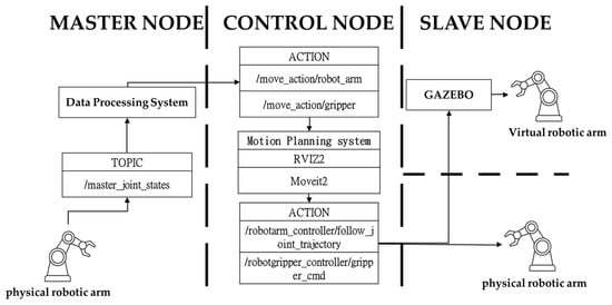
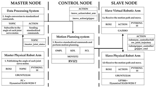
We developed a master-slave virtual-reality teleoperation system that employs ROS2 as the core communication and integration platform to establish a stable, real-time distributed control architecture. The system comprises the master, control, and slave nodes, with data exchange and synchronous control facilitated through the ROS2 communication mechanism (Figure 1).
Figure 1.
System components.
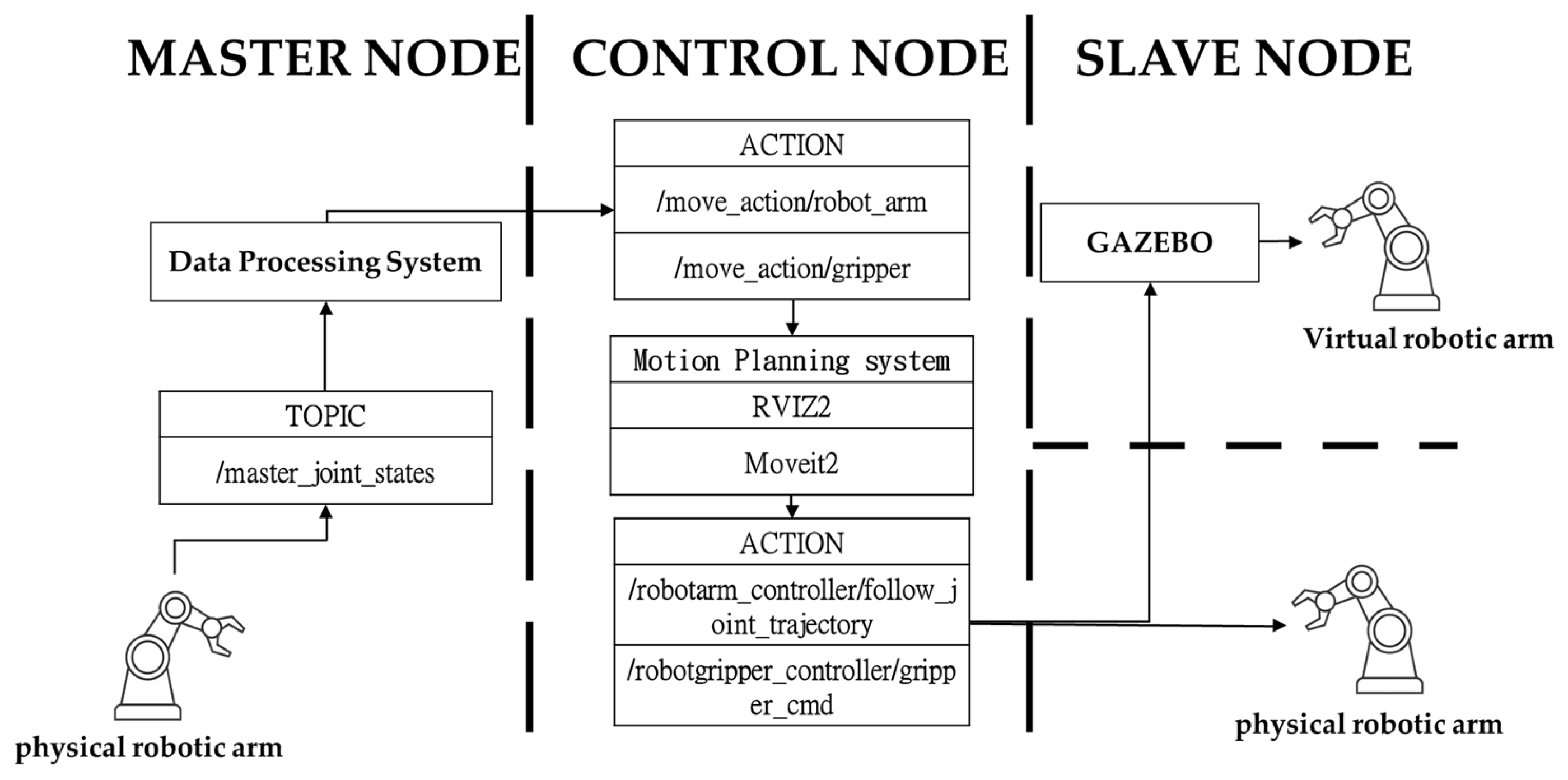
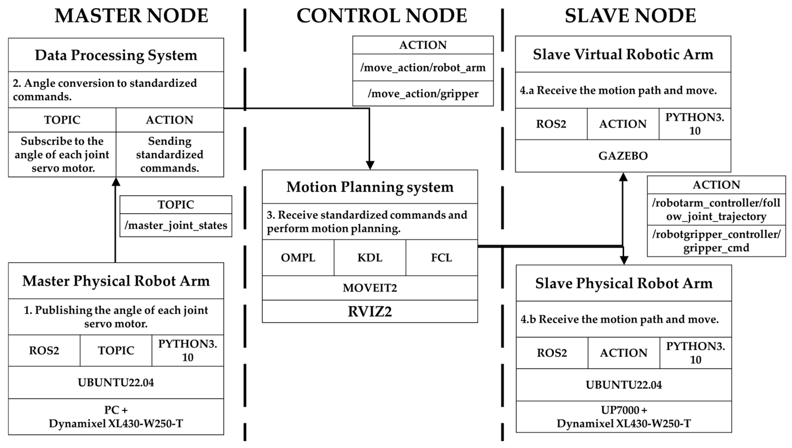
We employ ROS2 as the core communication and integration platform to establish a stable, real-time distributed control architecture. The system architecture, shown in Figure 2, is divided into the master, control, and slave nodes, which exchange data and collaborate through the ROS2 communication mechanism.
Figure 2.
System architecture.
The master node collects operational data from the operator’s interactions with the master robotic arm, including real-time joint angle values. These raw servo motor signals are processed through an angle conversion and data processing module, transforming them into standardized commands compatible with the MoveIt2 framework. These commands serve as the input for subsequent motion planning. The Master node uses a PC as its core platform and simultaneously runs the Gazebo virtual simulation environment and MoveIt2 motion planning calculations to generate real-time control commands that comply with kinematic constraints and safety regulations.
The control node integrates the RViz2, v11.2.28 for Ubuntu 22.04 LTS, visualization interface with the MoveIt2 motion planning framework. It receives standardized commands from the master node, calculates joint rotations using inverse kinematics, and performs path planning and collision detection. The resulting joint trajectory commands are transmitted synchronously to both the virtual environment and the physical robotic arm, ensuring safe and smooth execution of movements. The Control node also incorporates communication modules to guarantee the stability and reliability of control signals.
The slave node encompasses the Gazebo virtual simulation environment and the physical robotic arm control module, applying the digital twin concept to maintain high fidelity and consistency between the virtual model and the physical hardware. Based on the trajectories generated by the Control node, the Slave node drives both the virtual and physical robotic arms in synchrony, while simultaneously feeding real-time joint state information back to the Control node. This closed-loop architecture ensures robust coordination between virtual simulation and physical execution. The slave node uses the UP7000 as its primary core platform, receiving motion commands from the Control node and converting them into executable signals for the physical robotic arm. System specifications are summarized in Table 1, providing a detailed overview of the hardware and software configurations that support the proposed teleoperation framework.
Table 1.
System specifications.
2.1. Master Node
The master node is responsible for acquiring real-time joint data from the master robotic arm, including the joint angles of all axes and kinematic state parameters. These data are subsequently transmitted to the angle conversion system via the ROS2 Topic communication mechanism. The angle conversion system first preprocesses and filters the raw joint data to mitigate the influence of sensor noise on control stability. Subsequently, customized angle conversion equations are employed to transform the joint positions of the master robotic arm into standardized control commands compatible with the MoveIt2 kinematic model. Finally, the converted target joint angles are transmitted to the control node via the ROS2 Action communication mechanism.
where denotes the motor resolution conversion constant, expressed in encoder counts per radian (count/rad); represents the total encoder range for one complete revolution, which is 4096 counts; and represents the angular displacement of one complete revolution, corresponding to rad. Therefore, the calculated resolution constant is approximately 651.8986 count/rad. In this study, the value is retained to four decimal places to provide sufficient numerical precision for the angle conversion process.
The relationship used to convert the encoder position of each joint into radians is expressed as
where denotes the converted angular position of the -th joint in radians; represents the joint index; denotes the real-time encoder position of the -th motor in counts; represents the zero-point offset of the -th motor in counts; is the motor resolution conversion constant defined in Equation (1); and is the direction correction coefficient used to standardize the positive and negative rotation directions of each joint.
During the angle conversion process, the zero-point offset is first subtracted from the real-time encoder position to obtain the relative positional displacement of the -th joint. This step compensates for differences in the initial installation and zero-position settings of the motors. The relative encoder displacement is then converted into radians using the resolution constant , while the direction correction coefficient is applied to ensure a consistent definition of positive and negative rotation directions among all joints.
2.2. Control Node
The control node forms a comprehensive and stable central control system by utilizing the MoveIt2 motion planning framework, the RViz2 visualization interface, and the standardized Action communication mechanism. Once the target commands input by the master node are translated into executable motion trajectories by the control node, they synchronously drive both the virtual and physical robotic arms to perform consistent movements, thereby realizing a cyber-physical teleoperation control mode. At the motion planning level, the system integrates the Open Motion Planning Library, the Kinematics and Dynamics Library, and the Flexible Collision Library to effectively ensure that the generated paths comply with mechanical constraints and environmental safety requirements. At the control execution level, a time parameterization mechanism is employed to generate smooth and practically executable trajectories, further enhancing the overall stability and reliability of the system. The real-time visual feedback and path preview functionalities provided by RViz2 enable operators to fully comprehend the system status prior to execution, effectively mitigating the risk of operational errors.
2.3. Slave Node
The slave node is responsible for receiving the motion trajectory commands transmitted from the control node, synchronously driving both the virtual and physical robotic arms to execute the corresponding actions. By integrating the Gazebo simulation environment with the physical robotic arm, the system translates these motion commands into motor control signals via the ros2_control framework and standardized control interfaces. Simultaneously, the slave node continuously transmits joint state data and execution feedback back to the control node, maintaining the synchronization, consistency, and control stability of the cyber-physical system. The conversion relationship is expressed in Equation (3), where denotes the -th joint.
The target radian from the control node is first multiplied by the resolution constant , with the forward or reverse rotation direction determined by the sign coefficient of each axis. Subsequently, the offset value is added to reconstruct the absolute position of the motor. Finally, the resulting value is converted into an integer and constrained within a predefined safety range.
3. Result
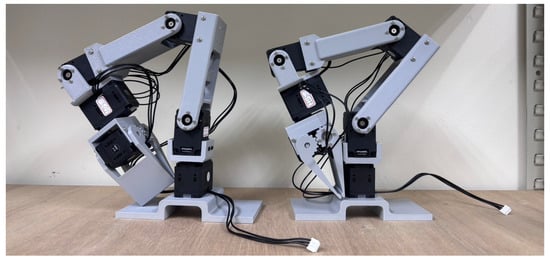
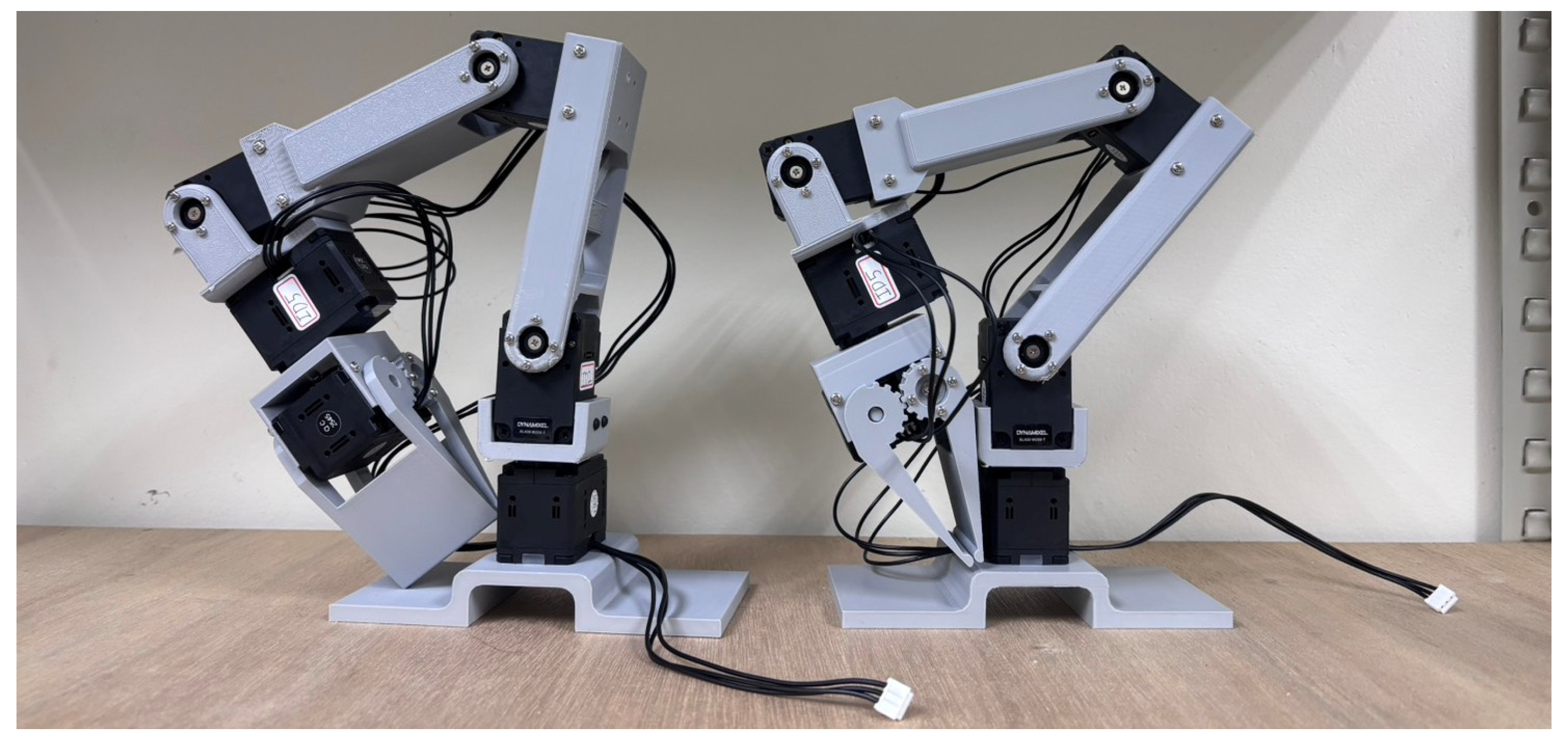
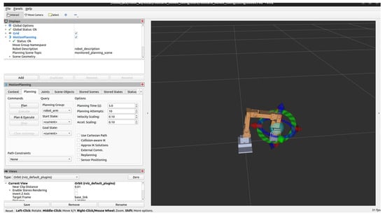
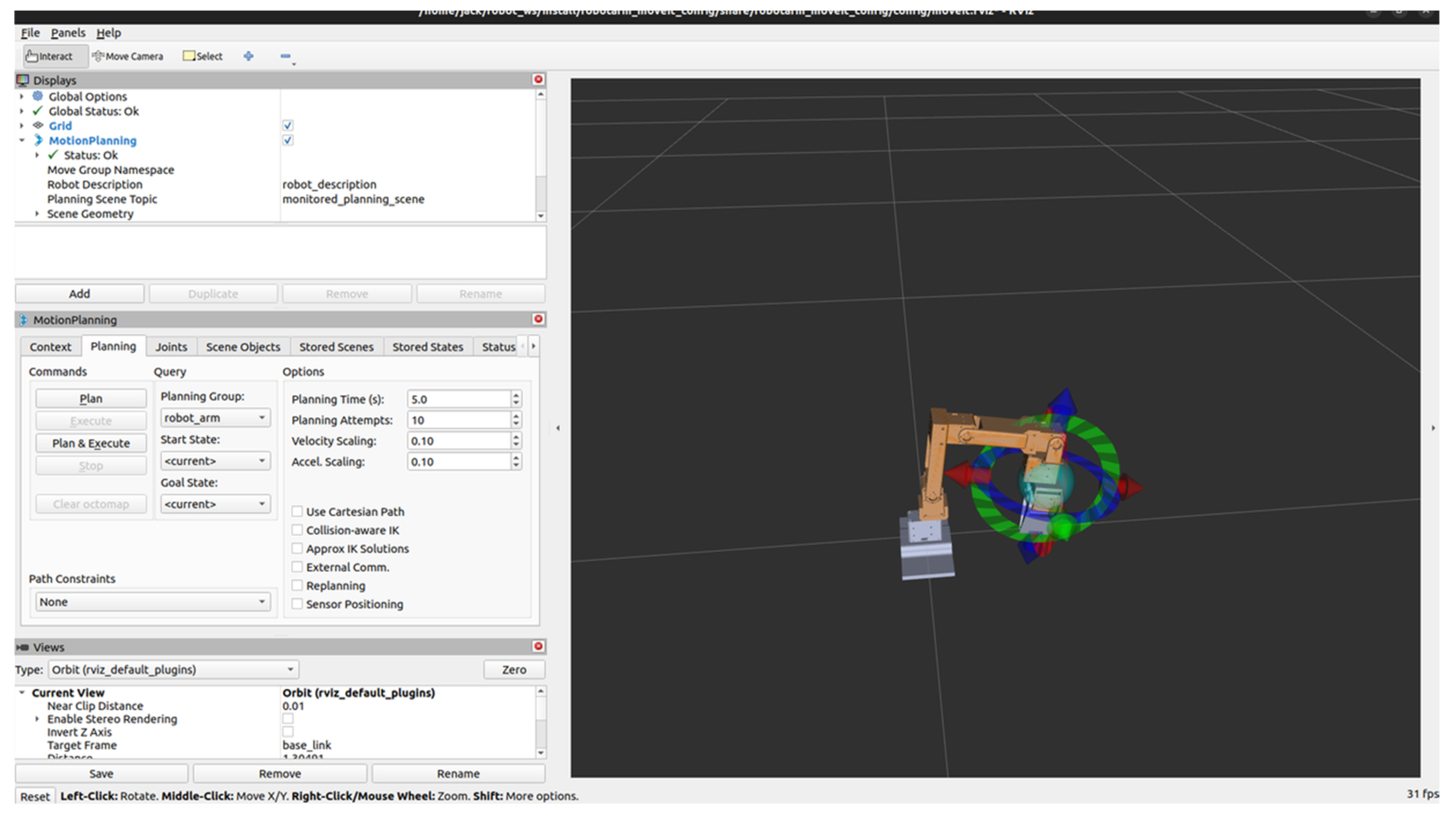
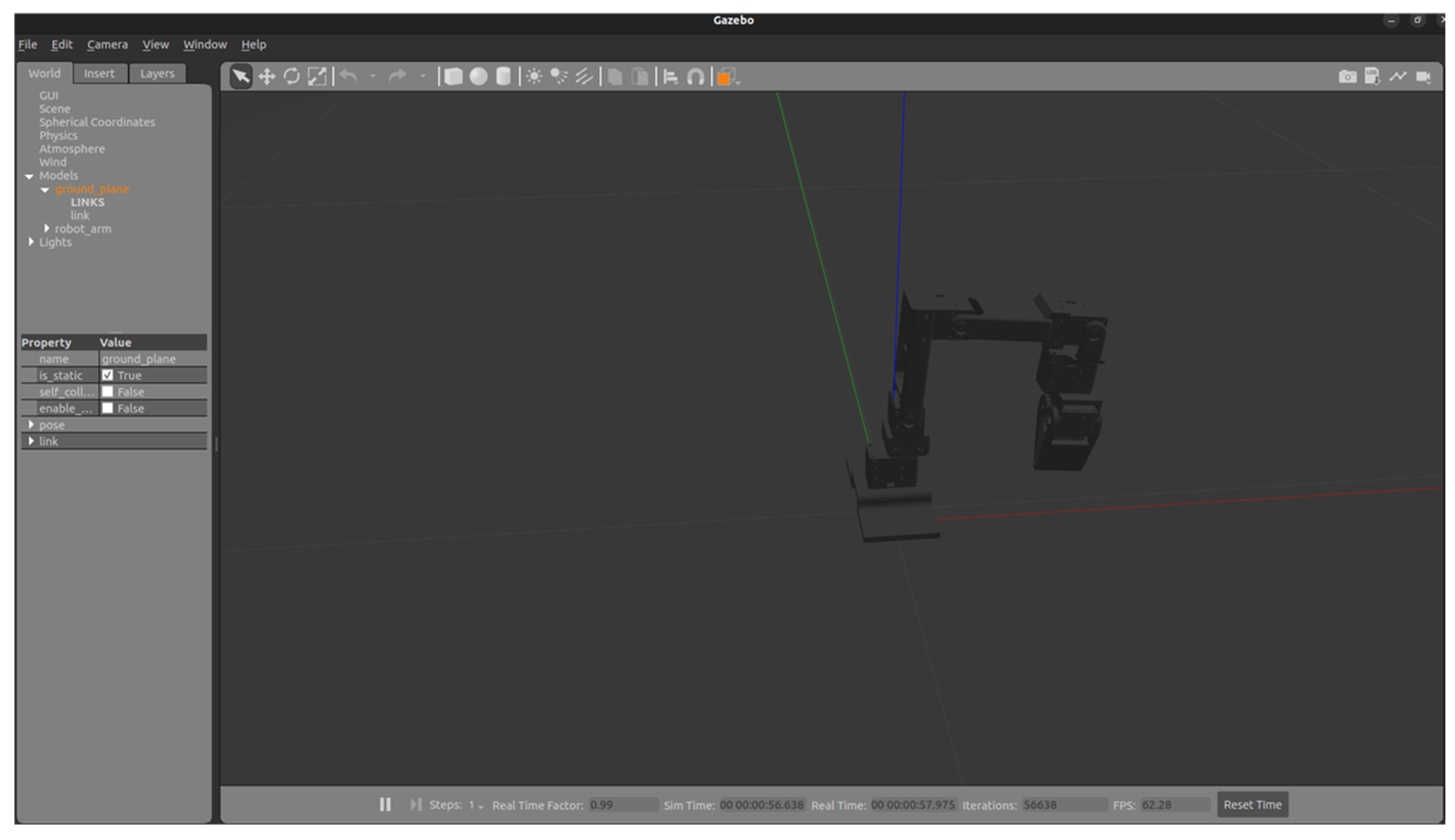
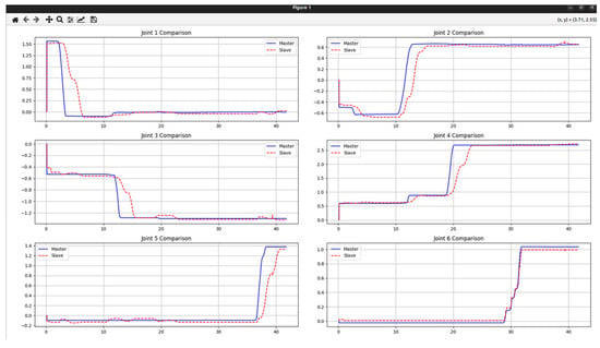
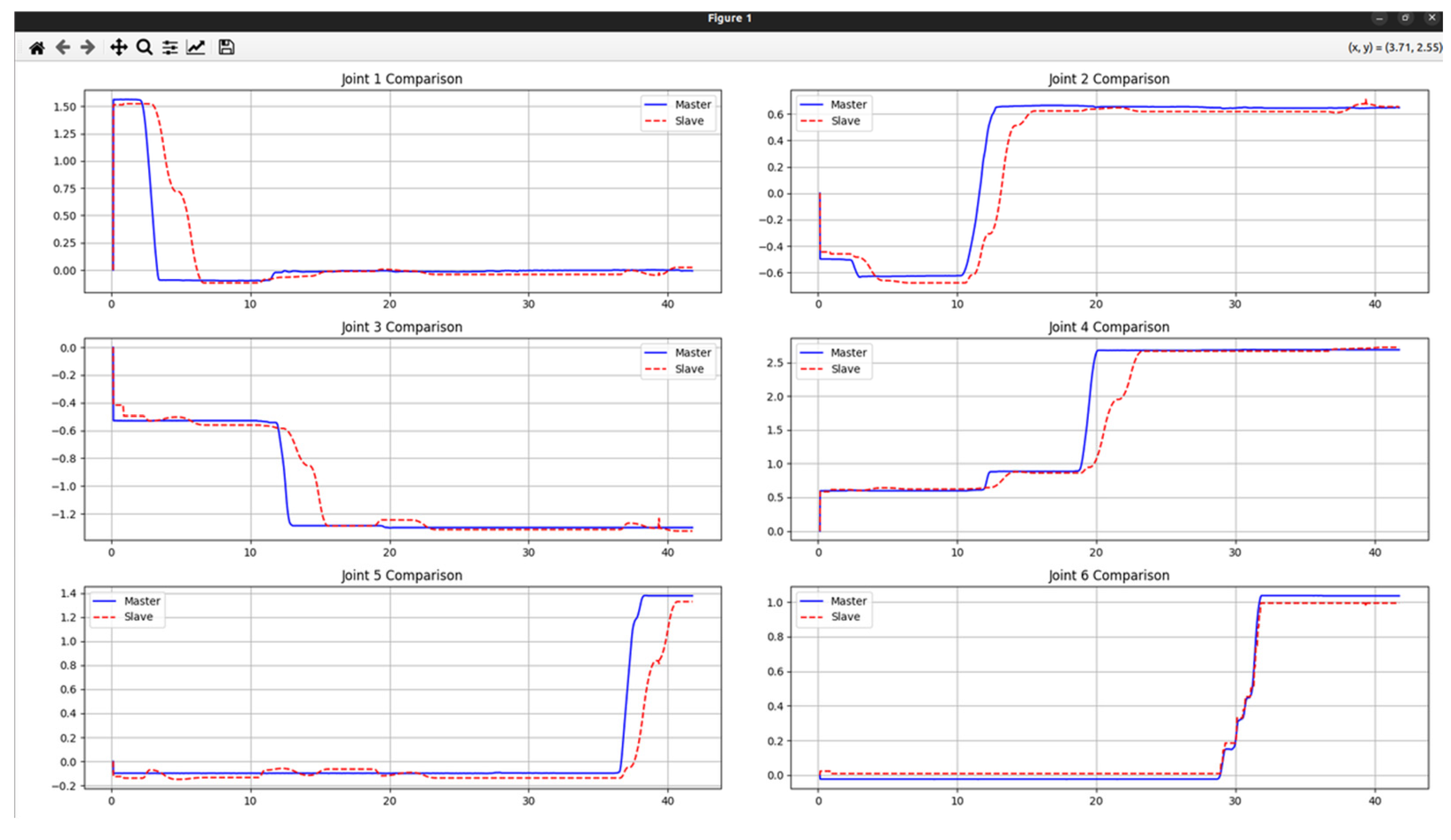
We implemented a ROS2-based master-slave virtual-reality teleoperation system integrating two physical master-slave robotic arms (Figure 3). To establish a digital twin, the software architecture combines MoveIt2 for path planning and collision detection with the Gazebo physics engine to simulate gravity, inertia, and joint dynamics (Figure 4 and Figure 5). This comprehensive integration enables accurate command transmission, motion preview, and safety assessment. System performance was validated through trajectory tracking experiments (Figure 6).
Figure 3.
Physical robotic arm.
Figure 4.
RVIZ2 simulation view.
Figure 5.
Gazebo simulation view.
Figure 6.
Motion trajectories of each joint (blue curve: master robotic arm; red curve: slave robotic arm).
Time-series plots comparing the master’s target inputs with the physical slave’s feedback demonstrate high consistency in overall trends. Minor phase and amplitude deviations observed during acceleration and deceleration were caused by communication latency and mechanical inertia, but these remained within acceptable limits and did not compromise path accuracy. The proposed architecture thus effectively maps operator intentions to the physical system, leveraging the virtual model to enhance operational safety, reliability, and engineering feasibility.
To verify control performance and synchronization accuracy, four operational modes were designed for testing: the arm standing upright with the gripper closed, the arm tilting forward with the gripper closed, the arm tilting backward with the gripper closed, and the arm tilting forward with the gripper open. These motion combinations allowed comprehensive evaluation of kinematic performance and synchronization errors under varying postures and load conditions. During the experiments, joint angle deviations between the master and slave arms were synchronously measured across all motion modes, with statistical results summarized in Table 2. The results indicate that the maximum and minimum joint angle errors across all axes were 4.54° and 0.26°, respectively. Overall errors remained within an acceptable margin, demonstrating that the proposed system possesses robust synchronization accuracy and reliable teleoperation performance.
Table 2.
Joint angles of master and slave arms under different motion modes.
4. Conclusions
To address the unintuitive interfaces, insufficient safety, and instability of traditional robotic teleoperation, we developed a master-slave virtual-reality teleoperation system based on ROS2. By integrating ROS2 communication (topics and actions) with the MoveIt2 framework, the architecture achieves low-latency data exchange, real-time path planning, and collision detection. Furthermore, coupling the physical arms with a Gazebo-based digital twin allows for virtual pre-verification and real-time visualization via RViz2. This mitigates physical trial-and-error risks while enhancing operational precision and situational awareness. Experimental validation demonstrated exceptional synchronization, maintaining joint angle errors strictly between 0.26° and 4.54°. The highly stable and scalable architecture effectively overcomes traditional teleoperation shortcomings, presenting substantial practical value for applications in smart manufacturing, remote maintenance, and high-risk environments.
Author Contributions
Conceptualization, H.-H.K.; methodology, H.-H.K., C.-H.C. and L.-Y.C.; software, C.-H.C.; validation, C.-H.C. and L.-Y.C.; formal analysis, C.-H.C. and L.-Y.C.; investigation, C.-H.C. and L.-Y.C.; resources, H.-H.K.; data curation, H.-H.K.; writing—original draft preparation, C.-H.C.; writing—review and editing, H.-H.K.; visualization, C.-H.C.; supervision, H.-H.K.; project administration, H.-H.K. All authors have read and agreed to the published version of the manuscript.
Funding
This research was funded by the Ministry of Education Teaching Practice Research Project, Taiwan, grant number MOE-114-TPRSK-0043-011Y1.
Institutional Review Board Statement
Not applicable.
Informed Consent Statement
Not applicable.
Data Availability Statement
The data presented in this study are available on request from the corresponding author.
Conflicts of Interest
The authors declare no conflict of interest.
References
- Mu, M.; Zhou, Y.; Wu, D. Digital Twins on Animal Husbandry: Insights and Application. Procedia Comput. Sci. 2022, 214, 1182–1189. [Google Scholar] [CrossRef] [Scilit]
- Audonnet, F.P.; Hamilton, A.; Aragon-Camarasa, G. A Systematic Comparison of Simulation Software for Robotic Arm Manipulation Using ROS2. In Proceedings of the 22nd International Conference on Control, Automation and Systems (ICCAS); IEEE: Piscataway, NJ, USA, 2022. [Google Scholar]
- Song, Q.; Xian, L. Control System Design of Telescopic Arm Remote-Control Robot. In Proceedings of the 6th International Conference on Artificial Intelligence and Advanced Manufacturing (AIAM 2024), Frankfurt, Germany, 20–21 October 2024. [Google Scholar]
- Cosmin, B.; Alexandru, A.; Sorin, T. Controlling Industrial Robots with Simulink. In Proceedings of the 15th International Conference on Electronics, Computers and Artificial Intelligence (ECAI); IEEE: Piscataway, NJ, USA, 2023; pp. 1–4. [Google Scholar]
- Ali, M.; Giri, S.; Liu, S.; Yang, Q. Digital Twin Synchronization: Bridging the Sim-RL Agent to a Real-Time Robotic Additive Manufacturing Control. arXiv 2025, arXiv:2501.18016. in press. [Google Scholar]
- He, J.; Yan, Z.; Wang, Y.; Jiang, Y.; Zeng, D.; Zhang, Z. Development of Robotic Arm Digital Twins via Edge-to-End Architecture. In Proceedings of the IEEE/CIC International Conference on Communications in China (ICCC Workshops); IEEE: Piscataway, NJ, USA, 2024; pp. 31–35. [Google Scholar]
- Córdova, L.A.; Vaca, J.P.; Sánchez, J.F.; Moya, V.; Pilco, A. Four-Degree Digital Twin Robotic Arm in Webots Environment. In Proceedings of the 6th International Conference on Robotics, Intelligent Control and Artificial Intelligence (RICAI); IEEE: Piscataway, NJ, USA, 2024; pp. 11–15. [Google Scholar]
- ROS 2 Documentation. Available online: https://docs.ros.org/en/humble/index.html (accessed on 28 October 2026).
- MoveIt 2 Documentation. Available online: https://moveit.picknik.ai/main/index.html (accessed on 28 October 2026).
- Gazbo Documentation. Available online: https://docs.ros.org/en/humble/Tutorials/Advanced/Simulators/Gazebo/Gazebo.html (accessed on 30 October 2026).
- Robot Visualization Documentation. Available online: https://slicer-ros2.readthedocs.io/en/v1.2/pages/robot-visualization.html (accessed on 30 October 2026).
- XL430-W250-T motor. Available online: https://emanual.robotis.com/docs/en/dxl/x/xl430-w250/ (accessed on 28 October 2026).

Disclaimer/Publisher’s Note: The statements, opinions and data contained in all publications are solely those of the individual author(s) and contributor(s) and not of MDPI and/or the editor(s). MDPI and/or the editor(s) disclaim responsibility for any injury to people or property resulting from any ideas, methods, instructions or products referred to in the content. |
© 2026 by the authors. Licensee MDPI, Basel, Switzerland. This article is an open access article distributed under the terms and conditions of the Creative Commons Attribution (CC BY) license.