


Abstract
This paper assesses the voltage ride-through (VRT) performance of a 1 MW grid-following photovoltaic (PV) plant connected to the IEEE 13-node unbalanced distribution feeder. Unbalanced RMS simulations in DIgSILENT PowerFactory 2024 SP5A (x64) consider single-phase-to-ground, phase-to-phase, and three-phase faults at the point of common coupling, as well as intentional islanding supported by a 3.5 MVA synchronous diesel generator. Under grid-connected operation, the PV plant remains connected for all simulated faults; the symmetrical three-phase case satisfies the Category-B ARCONEL-001/24 VRT envelope, while the asymmetric cases reveal phase-dependent behavior and temporary healthy-phase overvoltages. During islanding, the synchronous generator establishes the voltage and frequency reference, allowing the GFL PV plant to recover stable operation. The island frequency peaks at 60.929 Hz and settles near 60.664 Hz, both within the 59–61 Hz unlimited-operation band used as a regulatory reference. The results emphasize the importance of unbalanced modeling and grid-forming capability in inverter-rich distribution networks.
1. Introduction
The rapid growth of inverter-based resources (IBRs), particularly photovoltaic (PV) generation, is changing power-system dynamics and grid-interconnection requirements. Modern grid codes increasingly require generators to remain connected during short-duration voltage sags and to provide dynamic support instead of tripping. Voltage ride-through (VRT) capability is therefore commonly complemented by reactive-current injection and current-limiting requirements during faults [1,2,3,4,5,6].
Distribution-level VRT assessment is especially relevant because PV plants are often connected to feeders with appreciable phase unbalance and high R/X ratios, while practical faults are frequently single-phase or phase-to-phase. Grid-following (GFL) inverters depend on an external voltage reference, and their fault response is strongly influenced by the control strategy, reference frame, and current-limiting logic. Consequently, unbalanced voltage sags can produce phase-dependent responses that are not visible in balanced-network studies [7,8,9,10,11].
Islanded and weak-grid operation introduces an additional challenge. Frequency and voltage must be established by grid-forming capability, typically provided by a synchronous machine or a grid-forming inverter; a GFL PV plant can contribute fast current support but still requires a stable voltage and frequency reference [2,3,12,13]. This work therefore evaluates both conventional VRT performance and a fault-clearing sequence that produces intentional islanding.
The study uses the IEEE 13-node unbalanced feeder with a 1 MW PV plant represented by eight 125 kVA GFL inverters in DIgSILENT PowerFactory 2024 SP5A (x64) [7,14,15,16] (Supplementary Materials). Single-phase-to-ground, phase-to-phase, and three-phase faults are applied at the PV point of common coupling (PCC). A second scenario adds a 3.5 MVA synchronous diesel generator and forms an island after a substation fault. The symmetrical three-phase case is assessed formally against the Ecuadorian Category-B VRT requirement, while the asymmetric cases are used to characterize phase-resolved behavior [17].
2. Methodology
2.1. Test System and PV Plant Model
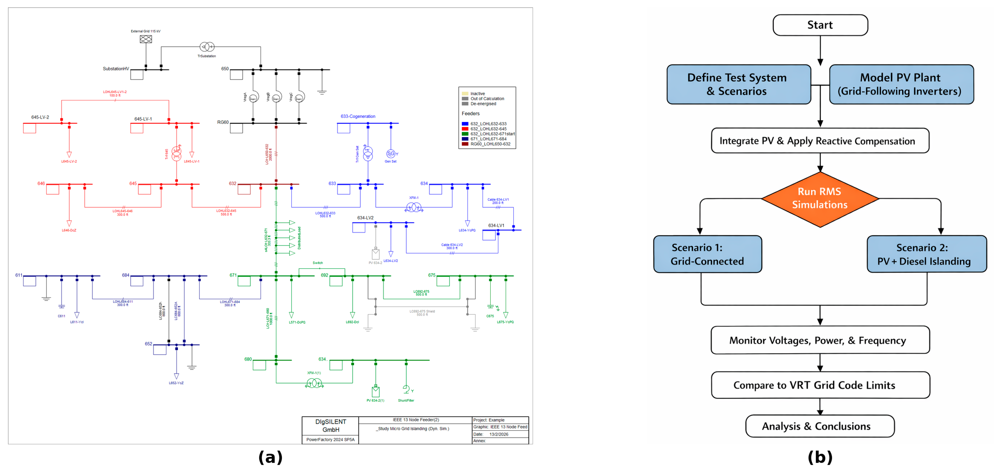
The IEEE 13-node feeder is a 4.16 kV radial benchmark with untransposed lines, single- and two-phase laterals, non-uniform loading, and strong phase unbalance. The network is supplied through a 115/4.16 kV substation transformer. A 1 MW PV plant is connected at bus 680 through a 0.48/4.16 kV step-up transformer and is represented by eight parallel 125 kVA three-phase GFL inverters. Figure 1a shows the feeder, and Figure 1b summarizes the assessment workflow.
Figure 1.
(a) IEEE 13-node unbalanced distribution feeder and PV connection point; (b) workflow for steady-state validation, RMS dynamic simulation, monitoring, and VRT compliance assessment. Arrows indicate the sequence of the assessment workflow; colors and shapes are used only to distinguish workflow stages and do not encode quantitative information.
The PV model uses the PowerFactory 2024 SP5A (x64) RMS dynamic template (DIgSILENT GmbH, Gomaringen, Germany) with local constant-voltage control and dynamic reactive-current support [14,15]. In GFL operation, a phase-locked loop provides synchronization and the active and reactive current references are related to the synchronous-frame voltage by
id = P/(3/2 Vd), iq = Q/(3/2 Vd)
During voltage sags, reactive current is prioritized subject to the inverter current limit,
and the dynamic support command follows a voltage-error law within the implemented limits,
√(id2 + iq2) ≤ Imax
iq* = KFRT (Vref − V)
The controller uses KFRT = 2.0 with a 0.1 p.u. dynamic-voltage-support deadband. The converter absolute-current limit is 1.0 p.u., with active-current limits 0 ≤ id ≤ 1.0 p.u. and reactive-current limits −1.0 ≤ iq ≤ 1.0 p.u. The active-power PI controller uses Kp = 0.005 and Ti = 0.03 s, with a 1 ms measurement delay. The PLL uses Kp = 20 and Ki = 3, frequency limits of 0.8–1.2 p.u., and blocking below 0.2 p.u. with a 100 ms filter.
A 0.8 MVAr shunt reactor is installed at the PCC to maintain pre-fault voltages close to 1 p.u. and avoid biased dynamic responses caused by steady-state overvoltage. Simulations represent midday PV availability.
2.2. Dynamic Scenarios and Compliance Assessment
Scenario 1 represents grid-connected operation. The same short-circuit event definition is used for the single-phase-to-ground, phase-to-phase, and three-phase faults at bus 680, changing only the fault type; in all cases Rf = 0.1 Ω, Xf = 0 Ω, the fault starts at t = 0 s, and it is cleared after 150 ms. Scenario 2 adds a 3.5 MVA, 6.6 kV synchronous diesel generator at bus 633 through a 6.6/4.16 kV transformer. The machine uses an acceleration time constant Tag = 5.0 s, an EXAC1 AVR (Ka = 200, Ta = 0.095 s, Te = 1.75 s), and a DEGOV1 governor with 5% droop, actuator gain K = 15, and combustion delay TD = 0.01 s. A solid three-phase substation fault (Rf = Xf = 0 Ω) is applied at t = 0 s and cleared after 100 ms; at the clearing instant, event-based switching opens the upstream connection and forms the island.
Line-to-line RMS voltages (VAB, VBC, and VCA) are monitored at buses RG60, 671, 684, and 680; PV P/Q, diesel electrical power, and island frequency are exported to Python 3.10.11. Under ARCONEL-001/24, the 1 MW plant is Category B, and Section 20.3 of ARCONEL-001/24 defines the power-park VRT envelope using line-to-line PCC voltages for a symmetrical fault [17]. Formal compliance is therefore evaluated with the three-phase case; asymmetric faults are complementary tests. Frequency settling time is the first instant after islanding at which frequency remains within ±0.01 Hz of its final value. Two isolated nonphysical export samples near 1.345 s were excluded without smoothing.
3. Results and Discussion
3.1. Grid-Connected Faults
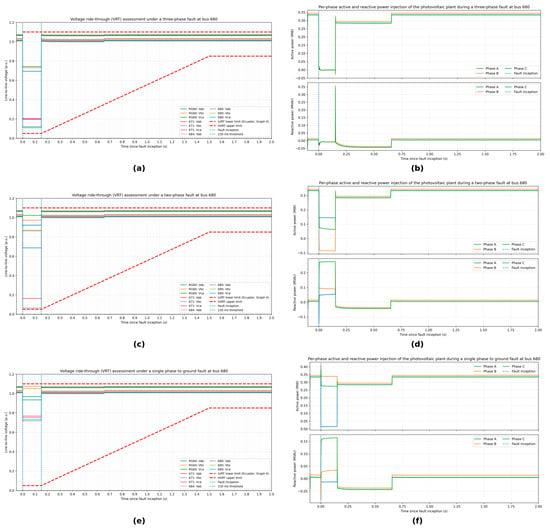
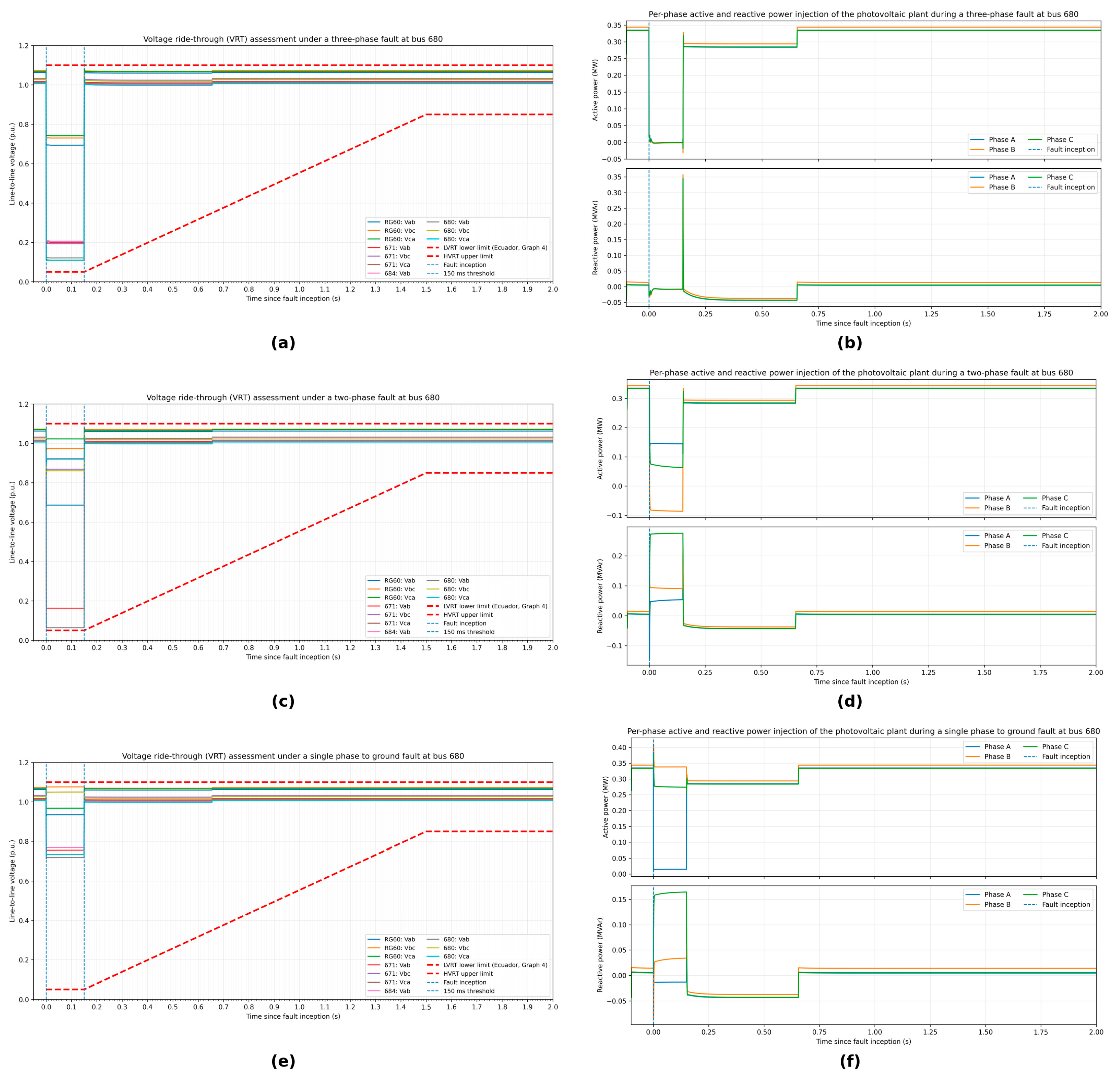
Figure 2 compares the grid-connected fault responses. For the three-phase fault, the minimum PCC line-to-line voltage is 0.1083 p.u.; PV active power falls nearly to zero during the 150 ms disturbance and recovers after clearing. The trajectory remains above the Category-B ARCONEL-001/24 VRT lower-bound envelope and therefore satisfies the formal ride-through requirement. The phase-to-phase fault produces a minimum PCC line-to-line voltage of 0.0619 p.u., while the other two line-to-line voltages remain at 0.8380 and 0.8959 p.u. The single-phase-to-ground fault gives a minimum PCC voltage of 0.7130 p.u. and a maximum healthy line-to-line voltage of 1.0496 p.u. at the PCC; the maximum among all monitored buses is 1.0759 p.u. at RG60. The PCC value remains within the 0.90–1.05 p.u. unlimited-operation band. The asymmetric cases are therefore interpreted as complementary phase-resolved assessments rather than separate formal ARCONEL VRT tests.
Figure 2.
Grid-connected fault responses at bus 680: three-phase fault, (a) line-to-line voltages and (b) PV active/reactive power; phase-to-phase fault, (c) voltages and (d) PV active/reactive power; single-phase-to-ground fault, (e) voltages and (f) PV active/reactive power.
3.2. Intentional Islanding with Synchronous Generation
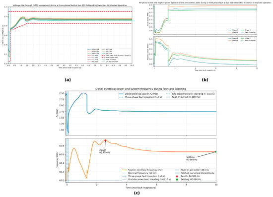
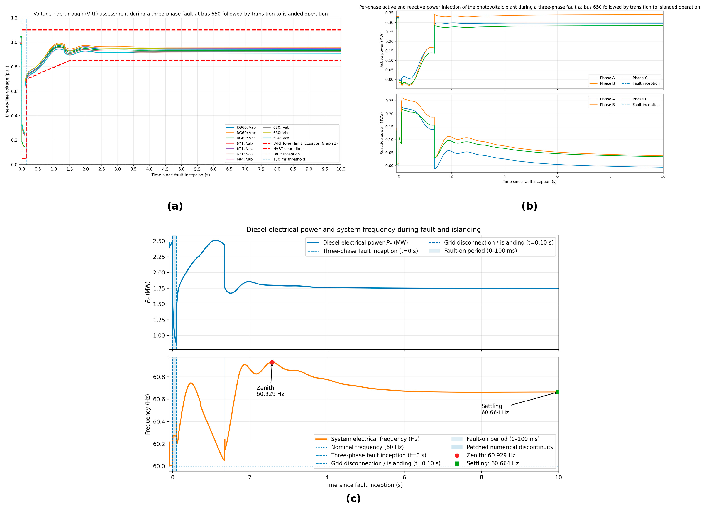
Figure 3 shows the transition to intentional islanding. During the 100 ms substation fault, the minimum PCC voltage is 0.2392 p.u.; the lowest value among the monitored buses is 0.1398 p.u. at RG60. Immediately before island formation, aggregate feeder load is approximately 2.658 MW, while the PV plant and diesel generator supply 0.800 MW and 1.983 MW, respectively. The magnitude of the upstream-grid active-power exchange is only about 24.5 kW (less than 1% of feeder load), indicating a near-balanced pre-islanding operating point. After upstream disconnection, the synchronous generator establishes the island voltage and frequency reference, and the GFL PV plant resumes stable injection. The physical frequency peak is 60.929 Hz, and the final quasi-steady value is 60.664 Hz; both remain within the 59–61 Hz unlimited-operation range of ARCONEL-001/24 [17]. Using the ±0.01 Hz criterion, settling occurs approximately 5.85 s after island formation.
Figure 3.
Intentional-islanding response: (a) line-to-line RMS voltages; (b) PV active/reactive power; (c) diesel electrical power and island frequency.
3.3. Comparative Summary and Engineering Implications
Table 1 summarizes metrics extracted directly from the PowerFactory RMS exports rather than approximate readings from the plots. The symmetrical three-phase case provides the formal Category-B VRT compliance check; the asymmetric faults quantify phase-specific behavior; and the islanding case quantifies the voltage and frequency transient after loss of the upstream reference.
Table 1.
Simulation-extracted metrics for the analyzed grid-connected and islanding scenarios.
The island response depends on synchronous-machine inertia and the generation–load mismatch: lower inertia or a larger mismatch would increase RoCoF and the frequency excursion, whereas greater inertia and closer balance would reduce it. A parametric sweep is left for future work.
Under asymmetric faults, the positive-sequence-oriented GFL control has no dedicated negative-sequence current regulator. Negative-sequence voltage therefore appears as an oscillatory term in the synchronous frame, producing a phase-dependent response and double-frequency components [9,11]. Such unbalance and healthy-phase overvoltage can increase dielectric stress and rotating-machine heating; dedicated negative-sequence compensation is left for future work.
The study is limited to a fixed midday PV operating point (~0.8 MW), one 1 MW penetration level, and fixed fault impedances. Lower irradiance would generally increase converter-current headroom for reactive support; higher fault impedance would reduce sag severity; and higher PV penetration could increase sensitivity to current limits, synchronization, and available grid-forming support. These trends require future parametric studies.
4. Conclusions
A VRT assessment of a 1 MW GFL PV plant on the IEEE 13-node unbalanced feeder was performed for grid-connected faults and intentional islanding. The symmetrical three-phase case reached 0.1083 p.u. at the PCC and satisfied the Category-B ARCONEL-001/24 VRT envelope. The phase-to-phase and single-phase-to-ground cases reached 0.0619 and 0.7130 p.u., respectively, and were treated as complementary unbalanced assessments. During the single-phase fault, the maximum healthy PCC voltage was 1.0496 p.u., within the unlimited-operation band. The results demonstrate the value of phase-resolved simulation beyond a balanced VRT check.
Intentional islanding remained stable with the 3.5 MVA synchronous diesel generator providing the voltage and frequency reference. Pre-islanding upstream-grid exchange was only about 24.5 kW. Frequency peaked at 60.929 Hz, approached 60.664 Hz, and settled within ±0.01 Hz of that value about 5.85 s after island formation. Thus, GFL VRT compliance alone does not guarantee autonomous operation; grid-forming capability remains essential. Future work should vary irradiance, fault impedance, PV penetration, and negative-sequence/grid-forming controls.
Supplementary Materials
The following supporting information can be downloaded at: https://www.mdpi.com/article/10.3390/engproc2026158037/s1, File S1: JIEE2026_VRT_Minimal_Dataset.csv, minimal numerical dataset supporting the main grid-connected VRT and intentional-islanding results; File S2: README_JIEE2026_VRT_Minimal_Dataset.txt, description of the supplementary dataset and column definitions.
Author Contributions
Conceptualization, E.N., J.C., G.S.P., E.J.S. and G.S.-Y.; methodology, E.N. and J.C.; software, E.N.; validation, E.N., J.C., G.S.P., E.J.S. and G.S.-Y.; formal analysis, E.N.; investigation, E.N.; resources, E.N.; data curation, E.N.; writing—original draft preparation, E.N.; writing—review and editing, E.N., J.C., G.S.P., E.J.S. and G.S.-Y.; visualization, E.N.; supervision, J.C., E.J.S. and G.S.-Y.; project administration, E.N. All authors have read and agreed to the published version of the manuscript.
Funding
This research was supported by Escuela Politécnica Nacional (EPN), Quito, Ecuador, through its Doctoral Program in Electrical Engineering, which provided institutional and financial support for the development of this work. No specific grant number was assigned to this institutional support.
Institutional Review Board Statement
Not applicable.
Informed Consent Statement
Not applicable.
Data Availability Statement
A minimal numerical dataset supporting the main findings is provided in the Supplementary Materials. The network was implemented from the IEEE 13-node feeder example available in DIgSILENT PowerFactory; the corresponding PowerFactory project contains third-party software/model content and is not redistributed. The IEEE test feeder is publicly available at https://site.ieee.org/pes-testfeeders/resources/ (accessed on 2 October 2026). Further inquiries may be directed to the corresponding author.
Acknowledgments
The authors thank Escuela Politécnica Nacional (EPN) for academic, technical, and institutional support. ChatGPT (OpenAI, San Francisco, CA, USA; GPT-5.6 Sol) was used for language editing, manuscript formatting, and assistance in organizing/cross-checking PowerFactory-exported numerical results; it was not used to generate simulation data or configure/execute simulations. All values, interpretations, and conclusions were reviewed and verified by the authors.
Conflicts of Interest
The authors declare no conflicts of interest.
Abbreviations
The following abbreviations are used in this manuscript:
| VRT | Voltage Ride-Through |
| PV | Photovoltaic |
| IBR | Inverter-Based Resource |
| GFL | Grid-Following |
| PCC | Point of Common Coupling |
| RMS | Root Mean Square |
| PLL | Phase-Locked Loop |
| AVR | Automatic Voltage Regulator |
| pu | Per Unit |
References
- Blaabjerg, F.; Yang, Y.; Yang, D.; Wang, X. Distributed Power-Generation Systems and Protection. Proc. IEEE 2017, 105, 1311–1331. [Google Scholar] [CrossRef] [Scilit]
- IEEE Std 1547-2018; IEEE Standard for Interconnection and Interoperability of Distributed Energy Resources with Associated Electric Power Systems Interfaces. IEEE: New York, NY, USA, 2018. Available online: https://standards.ieee.org/standard/1547-2018.html (accessed on 2 October 2026).
- IEEE Std 2800-2022; IEEE Standard for Interconnection and Interoperability of Inverter-Based Resources Interconnecting with Associated Transmission Electric Power Systems Interfaces. IEEE: New York, NY, USA, 2022. Available online: https://standards.ieee.org/ieee/2800/10453/ (accessed on 2 October 2026).
- European Commission. Commission Regulation (EU) 2016/631 of 14 April 2016 Establishing a Network Code on Requirements for Grid Connection of Generators. Off. J. Eur. Union 2016, L 112, 1–68. Available online: https://eur-lex.europa.eu/legal-content/EN/TXT/?uri=CELEX:32016R0631 (accessed on 2 October 2026).
- ENTSO-E. Network Code on Requirements for Generators (RfG). 2016. Available online: https://www.entsoe.eu/network_codes/rfg/ (accessed on 2 October 2026).
- Oon, K.H.; Tan, C.K.; Bakar, A.H.A.; Che, H.S.; Mokhlis, H.; Illias, H.A. Establishment of Fault Current Characteristics for Solar Photovoltaic Generator Considering Low Voltage Ride Through and Reactive Current Injection Requirement. Renew. Sustain. Energy Rev. 2018, 92, 478–488. [Google Scholar] [CrossRef] [Scilit]
- Kersting, W.H. Radial Distribution Test Feeders. In Proceedings of the 2001 IEEE Power Engineering Society Winter Meeting, Columbus, OH, USA, 28 January–1 February 2001; pp. 908–912. [Google Scholar] [CrossRef] [Scilit]
- Plet, C.A.; Brucoli, M.; McDonald, J.D.F.; Green, T.C. Fault Models of Inverter-Interfaced Distributed Generators: Experimental Verification and Application to Fault Analysis. In Proceedings of the 2011 IEEE Power and Energy Society General Meeting, Detroit, MI, USA, 24–28 July 2011; pp. 1–8. [Google Scholar] [CrossRef] [Scilit]
- Rolán, A.; Bogarra, S.; Bakkar, M. Integration of Distributed Energy Resources to Unbalanced Grids Under Voltage Sags With Grid Code Compliance. IEEE Trans. Smart Grid 2022, 13, 355–366. [Google Scholar] [CrossRef] [Scilit]
- Zhong, Q.-C.; Konstantopoulos, G.C. Current-Limiting Droop Control of Grid-Connected Inverters. IEEE Trans. Ind. Electron. 2016, 64, 5963–5973. [Google Scholar] [CrossRef] [Scilit]
- Li, Z.; Chan, K.W.; Hu, J.; Or, S.W. An Adaptive Fault Ride-Through Scheme for Grid-Forming Inverters under Asymmetrical Grid Faults. IEEE Trans. Ind. Electron. 2021, 69, 12912–12923. [Google Scholar] [CrossRef] [Scilit]
- Farrokhabadi, M.; Cañizares, C.A.; Simpson-Porco, J.W.; Nasr, E.; Fan, L.; Mendoza-Araya, P.A.; Tonkoski, R.; Tamrakar, U.; Hatziargyriou, N.D.; Lagos, D.; et al. Microgrid Stability Definitions, Analysis, and Examples. IEEE Trans. Power Syst. 2020, 35, 13–29. [Google Scholar] [CrossRef] [Scilit]
- Wang, J. Study of Inverter Control Strategies on the Stability of Microgrids Toward 100% Renewable Penetration. In Proceedings of IECON 2022—48th Annual Conference of the IEEE Industrial Electronics Society, Brussels, Belgium, 17–20 October 2022; pp. 1–6. [Google Scholar] [CrossRef] [Scilit]
- DIgSILENT GmbH. PowerFactory: Software Documentation and Manuals; DIgSILENT GmbH: Gomaringen, Germany, 2025. [Google Scholar]
- DIgSILENT GmbH. PV System Model and Templates (ElmPVsys/PV System Library); DIgSILENT GmbH: Gomaringen, Germany, 2025. [Google Scholar]
- Mahmood, F. Improving the Photovoltaic Model in PowerFactory. Master’s Thesis, KTH Royal Institute of Technology, Stockholm, Sweden, 2012. [Google Scholar]
- ARCONEL. Regulación Nro. ARCONEL-001/24, Código de Conexión del Sistema Eléctrico Ecuatoriano; Agencia de Regulación y Control de Electricidad: Quito, Ecuador, 2024. Available online: https://arconel.gob.ec/regulaciones-2024/ (accessed on 2 October 2026).

Disclaimer/Publisher’s Note: The statements, opinions and data contained in all publications are solely those of the individual author(s) and contributor(s) and not of MDPI and/or the editor(s). MDPI and/or the editor(s) disclaim responsibility for any injury to people or property resulting from any ideas, methods, instructions or products referred to in the content. |
© 2026 by the authors. Licensee MDPI, Basel, Switzerland. This article is an open access article distributed under the terms and conditions of the Creative Commons Attribution (CC BY) license.