


Abstract
Dental implants are widely used to replace missing teeth. The aim of this study was to develop a patient-specific screw-type dental implant using a computed tomography (CT)-based modeling approach and to evaluate its biomechanical behavior through finite element analysis. A mandibular model was reconstructed from CT data and used as the basis for implant design in a CAD environment. Finite element simulations were performed under a physiological load of 300 N to compare the mechanical response of Ti-6Al-4V and 3Y-TZP implant materials. The results revealed that both materials exhibited safe mechanical behavior, with maximum von Mises stresses of 63 MPa and 98.863 MPa for Ti-6Al-4V and 3Y-TZP, respectively. Although zirconia showed higher stress levels, it exhibited lower deformation due to its greater stiffness. The findings confirm the applicability of CT-based design and finite element analysis for evaluating and optimizing dental implant performance.
1. Introduction
Dental implants have become an established treatment option for the replacement of missing teeth, with osseointegration forming the basis of their long-term clinical success. Since the introduction of modern implantology, continuous developments in implant geometry, surface characteristics, and biomaterials have contributed to improved clinical outcomes. Titanium and titanium alloys remain the most widely used implant materials, while zirconia has emerged as an alternative because of its favorable biological and aesthetic properties [1,2].
The development of digital technologies has further changed the planning and design of dental implants. Computed tomography (CT) provides three-dimensional information about the anatomy and morphology of the jaw and can therefore be used to create patient-specific digital models. Such models allow implant geometry to be considered together with the anatomical conditions of the implantation site. In previous work, a high-quality geometric reconstruction of the human mandible from CT data was developed, providing a suitable basis for further CAD-based and numerical investigations [3].
The mechanical behavior of an implant–bone system is affected by several parameters, including implant dimensions, thread geometry, bone quality, material properties, and loading conditions. For example, variations in bone quality and implant geometry can considerably influence the resulting stress and displacement fields [4]. The elastic modulus of the implant material is also relevant because the stiffness difference between the implant and the surrounding bone affects load transfer within the system [5]. These factors make the mechanical evaluation of implant designs an important part of implant development.
Finite element analysis (FEA) is widely used for this purpose because it allows stress and deformation to be investigated under defined loading and boundary conditions. Previous studies have applied FEA to evaluate stress distribution, micromotion, and safety factors in different dental implant configurations [5]. When combined with CT-based anatomical models, the method provides an opportunity to assess implant designs under patient-specific geometric conditions without relying exclusively on experimental testing.
Despite the extensive use of numerical methods in implant research, the mechanical response of different implant materials can vary considerably even when the same implant geometry and loading conditions are applied. In particular, the difference in elastic stiffness between titanium alloys and zirconia may influence both stress distribution and deformation. A direct comparison using the same CT-derived mandibular geometry and identical simulation conditions can therefore provide useful information for the early-stage evaluation of implant designs.
The aim of this study was to develop a screw-type dental implant based on a CT-reconstructed mandibular model and to compare the biomechanical behavior of Ti-6Al-4V and 3Y-TZP zirconia using finite element analysis. The same implant geometry, anatomical model, boundary conditions, and loading conditions were applied to both materials. The resulting stress, deformation, and safety factors were evaluated to identify differences in their mechanical response and to assess the applicability of the CT-based modeling and simulation workflow for dental implant design.
2. Materials and Methods
2.1. CT-Based Mandibular Model Preparation
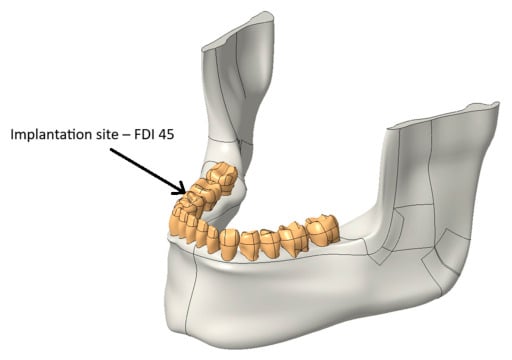
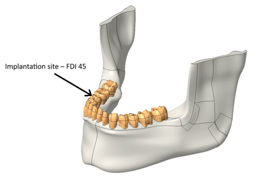
A patient-specific mandibular model was reconstructed from computed tomography (CT) images and used as the basis for implant design and biomechanical analysis. The CT dataset was processed to obtain a three-dimensional representation of the mandible and the remaining dentition, providing an accurate description of the anatomical structures (Figure 1) [3].
Figure 1.
CT-based reconstructed mandibular model used for implant design and finite element analysis.
The reconstructed model included both cortical and trabecular bone, allowing the implant to be evaluated under realistic anatomical conditions. The implant was planned in the region of the right mandibular second premolar (FDI tooth 45), which generally corresponds to D2–D3 bone quality according to the commonly used bone density classification. This location was selected because it represents a typical clinical indication for implant-supported restoration [4].
The reconstructed mandibular geometry was imported into the Creo Parametric 12 environment, where it served as the reference model throughout the design process. Using CT-derived anatomical data made it possible to adapt the implant geometry to the available bone morphology and to create a patient-specific model suitable for finite element analysis.
2.2. Implant Design
The implant was designed in Creo Parametric 12 using design recommendations collected from the literature. The selected dimensions, material, and thread geometry were based on parameters most frequently reported for commercially available dental implants.
Titanium alloys are currently the most widely used implant materials because they combine high mechanical strength with excellent biocompatibility and corrosion resistance. For this reason, Ti-6Al-4V was chosen as the reference material for the developed implant model [6].
A tapered screw-type implant configuration was selected, as this geometry is commonly applied in clinical practice and provides good primary stability after insertion. The implant length was defined as 11.1 mm, while the maximum diameter was 4.98 mm, corresponding to typical dimensions used in the posterior mandibular region [7].
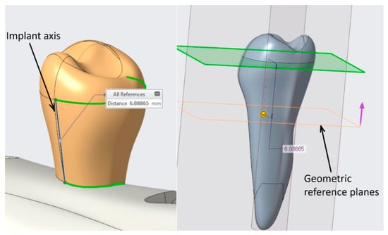
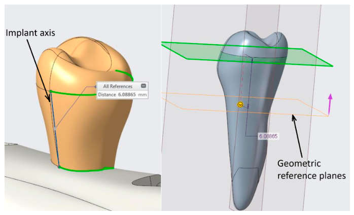
The geometry of the extracted tooth was used as the starting point for the design procedure. First, the long axis of the original root was determined to define the implant axis (Figure 2). A revolved solid was then created to generate the tapered implant body. The external thread was added in the next design step using a square thread profile, which has been reported to reduce shear stresses at the implant–bone interface compared with several alternative thread geometries.
Figure 2.
Definition of the implant axis and geometric reference planes during the design process.
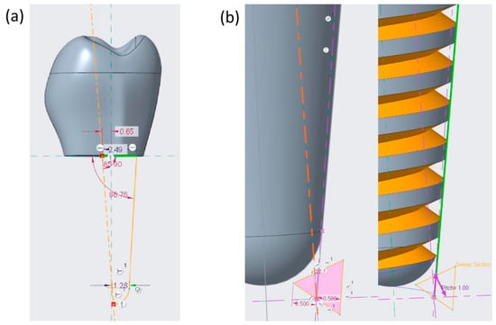
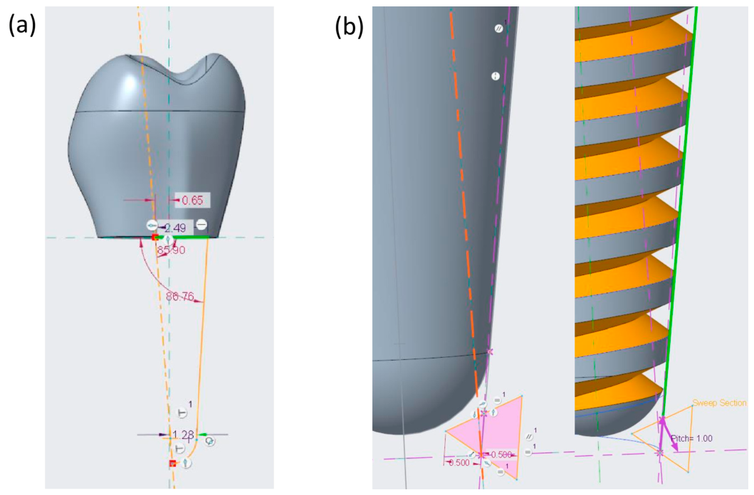
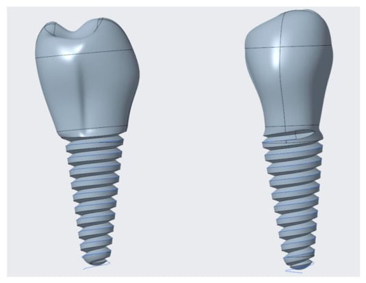
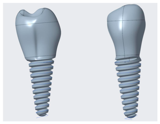
The final implant incorporated a thread depth of 0.5 mm and a thread pitch of 1.0 mm (Figure 3) [8]. Additional modifications were introduced in the cervical region to ensure a smooth transition at the thread termination and to avoid sharp geometric discontinuities that could increase local stress concentrations (Figure 4) [9].
Figure 3.
(a) Sketch of the tapered body design; (b) Designing thread depth and pitch.
Figure 4.
Final screw-type implant geometry developed in Creo Parametric 12.
2.3. Finite Element Model
The biomechanical performance of the designed implant was evaluated using finite element analysis performed in ANSYS 2025 R2. After completing the CAD model, the implant was positioned in the reconstructed mandibular geometry according to the planned clinical location.
The finite element model consisted of the implant together with the surrounding cortical and trabecular bone. Material properties were assigned according to published literature values (Table 1). All materials were assumed to be homogeneous, isotropic, and linearly elastic, which is a commonly accepted approach in dental implant simulations [10].
Complete osseointegration was represented by defining a bonded contact between the implant surface and the surrounding bone. Although this assumption represents an ideal clinical condition, it is widely used in finite element studies to evaluate implant performance after successful healing.
To prevent rigid body motion, appropriate boundary conditions were applied to the mandibular model [11]. A static vertical load of 300 N was applied to the implant-supported crown to simulate physiological masticatory loading [12] (Figure 5).
Figure 5.
Location of Support Points and Load Points.
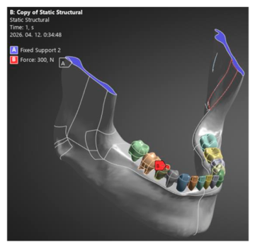
The finite element mesh was generated using three-dimensional solid elements, with local mesh refinement around the implant threads and the implant–bone interface, where high stress gradients were expected (Figure 6) [1,5,13]. The numerical simulations were then carried out to determine the stress distribution and deformation of the implant system.
Figure 6.
Finite element model and mesh used for numerical simulations.
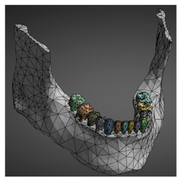
Table 1.
Material properties used in the finite element simulations [1,5,13].
3. Results
Finite element analyses were carried out under identical boundary conditions using a vertical load of 300 N, representing physiological masticatory loading [14].
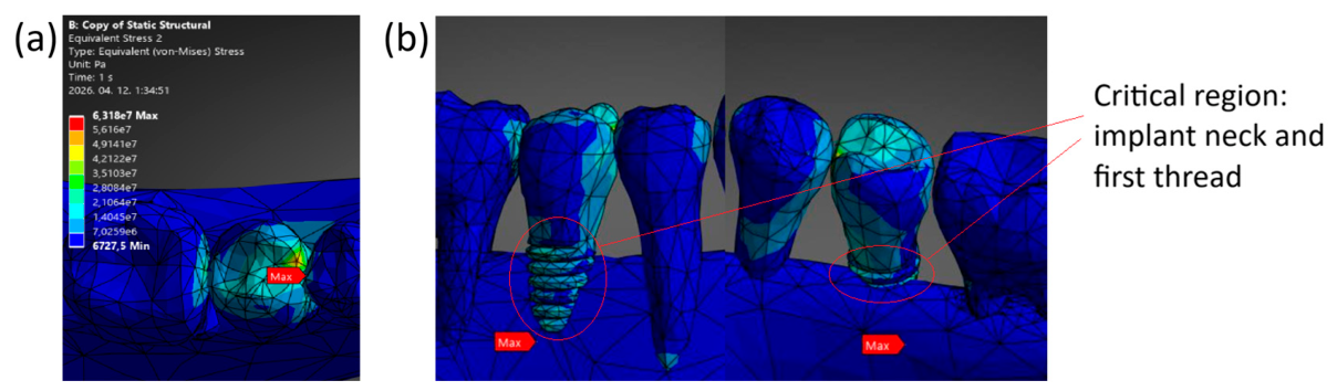
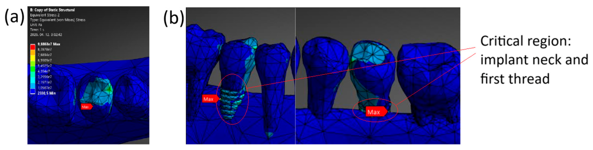
The calculated von Mises stress distributions showed similar patterns for both implant materials. The highest stress concentrations were located in the cervical region of the implant, close to the implant–bone interface, with additional local peaks around the first implant threads (Figure 7 and Figure 8). A detailed view of these regions is provided in the enlarged sections of Figure 7 and Figure 8, where the critical stress concentrations can be identified more clearly. These regions represent the primary load transfer zones between the implant and the surrounding bone [5,15,16].
Figure 7.
(a) Von Mises stress distribution in the Ti-6Al-4V implant under a 300 N load and (b) enlarged image of the cervical region/first thread area without cortical bone.
Figure 8.
(a) Von Mises stress distribution in the 3Y-TZP implant under a 300 N load and (b) enlarged image of the cervical region/first thread area without cortical bone.
For the Ti-6Al-4V implant, the maximum von Mises stress was 63 MPa and was located in the cervical region of the implant (Figure 7). Based on the material yield strength, the calculated safety factor was 13.49 (Equation (1)), indicating safe operation under the applied loading conditions [4,17].
For the 3Y-TZP implant, the maximum von Mises stress reached 98.863 MPa, with the critical region similarly located near the implant neck and implant–bone interface (Figure 8). Although this value was higher than that obtained for Ti-6Al-4V, the calculated safety factor remained 6.07 (Equation (2)), confirming that the implant operated within the allowable mechanical limits.
The total deformation of the titanium implant reached 2.80 × 10⁻⁴ m, whereas the zirconia implant showed a lower maximum deformation of 1.55 × 10⁻⁴ m. The reduced displacement of the zirconia model reflects the higher stiffness of the material [18].
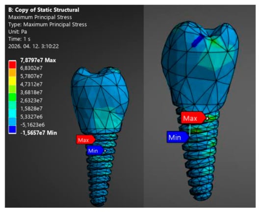
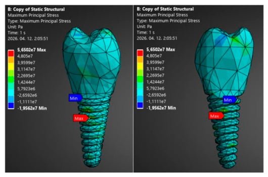
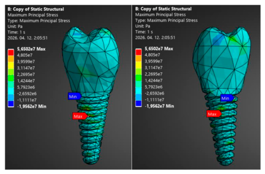
Since 3Y-TZP is a brittle ceramic material, the maximum principal stress was additionally evaluated to characterize its tensile stress state. This criterion provides complementary information to the von Mises stress, which was used for the yield-based assessment of the investigated materials. The maximum principal stress obtained for the 3Y-TZP implant was 78.8 MPa, resulting in a safety factor of 12.7 when compared with the 1000 MPa strength value given in Table 1 (Equation (3)) (Figure 9).
Figure 9.
Maximum principal stress of 3Y-TZP.
For comparison, the maximum principal stress for the Ti-6Al-4V implant was 56.5 MPa, corresponding to a safety factor of 16.8 when compared with its 950 MPa tensile strength (Equation (4)) (Figure 10).
Figure 10.
Maximum principal stress of Ti-6Al-4V.
A comparison of the numerical results is presented in Table 2. Both implant materials remained within their allowable mechanical limits under the applied loading conditions. The titanium alloy exhibited lower stress values, whereas the zirconia implant showed lower deformation due to its higher elastic modulus [19].
Table 2.
Comparison of mechanical performance indicators for the investigated implant materials.
4. Discussion
The finite element analyses showed that both investigated implant materials performed safely under the applied loading conditions. Although Ti-6Al-4V and 3Y-TZP differ considerably in their mechanical properties, similar stress distributions were obtained. The highest stresses occurred in the cervical region and around the implant–bone interface, identifying these areas as the main load transfer regions.
This stress localization is consistent with previous finite element investigations. Dalia et al. [9] reported that the implant neck and first thread region are exposed to the highest stresses because these areas transfer most of the occlusal load to the surrounding bone. Similar stress concentrations were observed in the present study, particularly around the first implant threads.
The maximum von Mises stress reached 63 MPa for the Ti-6Al-4V implant and 98.863 MPa for the 3Y-TZP implant. Similar higher stress levels within zirconia implants compared with titanium have been reported in recent finite element studies, which attributed this behavior to the higher elastic modulus and stiffness of zirconia [20]. In contrast, Villabona Lopez et al. [21] reported lower peri-implant bone stress peaks for zirconia implants compared with titanium under axial and oblique loading. These differences highlight the influence of implant geometry, loading conditions, and the evaluated region on the resulting stress distribution. In the present study, the higher stress within the zirconia implant is therefore interpreted primarily in relation to its higher stiffness and the specific loading and patient-specific anatomical conditions applied in the model.
The deformation results followed the same trend. The zirconia implant showed lower deformation than the titanium alloy because of its higher stiffness. However, the difference in elastic modulus between the implant and surrounding bone should also be considered. Both materials are considerably stiffer than bone, with a greater stiffness mismatch for 3Y-TZP. This difference can affect load transfer and local stress distribution at the implant–bone interface. Nevertheless, the present model does not allow direct conclusions regarding bone resorption or long-term biological response because bone remodeling and patient-specific anisotropic behavior were not included.
The calculated safety factors confirmed an adequate mechanical reserve for both materials under the investigated loading conditions. Ti-6Al-4V exhibited higher safety margins, whereas 3Y-TZP also remained within the investigated mechanical limits. Menacho-Mendoza et al. [17] similarly reported high safety factors for dental implant systems under physiological loading conditions.
From a clinical perspective, titanium alloys remain widely used because of their established long-term performance, while zirconia represents an alternative material with increasing clinical interest. The present results indicate that both materials remained within the investigated mechanical safety limits, although their different elastic properties resulted in distinct stress and deformation responses.
The present study has several limitations. The numerical model assumed homogeneous, isotropic, and linearly elastic material behavior, while complete osseointegration was represented by a bonded contact condition. In reality, mandibular bone exhibits heterogeneous and anisotropic mechanical behavior, which is influenced by its microstructure and local bone quality. An anisotropic bone model could therefore provide a more realistic representation of load transfer and may result in different local stress distributions, particularly near the implant–bone interface. Nevertheless, the simplified material model was considered appropriate for the comparative assessment of the two implant materials performed in the present study. Only static vertical loading was investigated. Future studies should therefore include patient-specific anisotropic bone properties, dynamic and cyclic loading, and more realistic bone material models to improve the predictive capability and clinical relevance of the simulations.
5. Conclusions
A patient-specific screw-type dental implant was designed from a CT-based mandibular model and evaluated using finite element analysis. The applied workflow combined medical imaging, CAD modeling, and numerical simulation to assess the biomechanical performance of the implant under physiological loading conditions.
Both investigated implant materials, Ti-6Al-4V and 3Y-TZP zirconia, demonstrated safe mechanical behavior under the applied 300 N load. In both models, the highest stresses developed in the cervical region of the implant and around the implant–bone interface. The titanium alloy exhibited lower stress values and higher safety factors, whereas the zirconia implant showed lower deformation because of its higher stiffness. Despite the higher von Mises stress obtained for 3Y-TZP, the calculated safety factor confirmed that the implant remained within the allowable mechanical limits.
The obtained results demonstrate that CT-based implant design combined with finite element analysis provides a practical tool for evaluating implant performance before clinical application. The comparison of Ti-6Al-4V and 3Y-TZP also indicates that both materials are mechanically suitable for dental implant applications, while each offers different mechanical characteristics that should be considered during implant selection and design.
Future research will focus on incorporating more realistic material models, patient-specific bone properties, and dynamic loading conditions to improve the predictive capability of the numerical simulations.
Author Contributions
Methodology: K.P. and I.A.P.; Software: K.P. and H.P.; I.A.P.; Validation: K.P. and I.A.P.; Formal analysis: K.P.; Investigation: H.P.; Resources: K.P. and I.A.P.; Data curation: H.P.; Writing—original draft preparation: H.P.; Writing—review and editing: K.P.; Visualization: H.P.; Supervision: K.P.; Project administration: K.P.; Funding acquisition: K.P. All authors have read and agreed to the published version of the manuscript.
Funding
This research received no external funding.
Institutional Review Board Statement
Not applicable.
Informed Consent Statement
Not applicable.
Data Availability Statement
The original contributions presented in this study are included in the article. Further inquiries can be directed to the corresponding author.
Conflicts of Interest
The authors declare no conflict of interest.
References
- Buser, D.; Sennerby, L.; De Bruyn, H. Modern implant dentistry based on osseointegration: 50 years of progress, current trends and open questions. Periodontology 2000 2017, 73, 7–21. [Google Scholar] [CrossRef] [Scilit] [PubMed]
- Bosshardt, D.D.; Chappuis, V.; Buser, D. Osseointegration of titanium, titanium alloy and zirconia dental implants: Current knowledge and open questions. Periodontology 2000 2016, 73, 22–40. [Google Scholar] [CrossRef] [Scilit] [PubMed]
- Papp, K.; Piros, I.A.; Deák, B. High quality geometric reconstruction of human mandible. MM Sci. J. 2024, 2024, 7664–7670. [Google Scholar] [CrossRef] [Scilit]
- Chih, C.; Jing, C.; Chen, C. Using optimization approach to design dental implant in three types of bone quality—A finite element analysis. J. Dent. Sci. 2024, 20, 126–136. [Google Scholar] [CrossRef] [Scilit] [PubMed]
- Juliana, D.; Alves, B.M.B.C.; Valente, M.L.C.; Reis, A.C. Influence of the modulus of elasticity of dental implants on the distribution of stresses in the alveolar bone by the finite element method: A systematic review. J. Oral Maxillofac. Surg. Med. Pathol. 2023, 35, 383–389. [Google Scholar] [CrossRef] [Scilit]
- Masha, F. Digitalization of the Golden Standard of Implantology, Cortex Articles. Available online: https://cortex-dental.com/wp-content/uploads/2021/10/12.-Digitalization-of-the-Golden-Standard-of-Implantology-Dr.-Masha-Fraibert-DMD.pdf (accessed on 13 October 2026).
- Hermann, P.; Kispélyi, B. Fogpótlástan 2. Kötet; Semmelweis Kiadó: Budapest, Hungary, 2022; pp. 731–742, 746–756. [Google Scholar]
- Qian, L.; Todo, M.; Matsushita, Y.; Koyano, K. Effects of implant diameter, insertion depth, and loading angle on stress/strain fields in implant/jawbone systems: Finite element analysis. Int. J. Oral Maxillofac. Implants 2009, 24, 877. [Google Scholar]
- Shaker, D.; Elkhadem, A.; Rasoul, M.A.; Askar, M.G. Influence of implant thread’s cross-sectional design on the micromotion of the implants in different bone qualities: Finite element analysis. Adv. Dent. J. 2021, 3, 1–11. [Google Scholar] [CrossRef] [Scilit]
- Lakatos, É. A Csont Mikroszerkezetének Mechanikai Viselkedése Fogászati Implantátumok Környezetében. Doctoral Dissertation, Budapest University of Technology and Economics, Budapest, Hungary, 2011. [Google Scholar]
- Ding, X.; Liao, S.H.; Zhu, X.H.; Zhang, X.H.; Zhang, L. Effect of Diameter and Length on Stress Distribution of the Alveolar Crest around Immediate Loading Implants. Clin. Implant. Dent. Relat. Res. 2009, 11, 279–287. [Google Scholar] [CrossRef] [Scilit] [PubMed]
- Ina, N.; Moede, C.; Koenig, A.; Sobotta, B.A.J.; Hopfenmüller, W.; Jockusch, J. An Evaluation of Reference Bite Force Values: Investigating the Relationship Between Dental Prosthetic Restoration and Bite Force in a Cross-Sectional Study. J. Clin. Med. 2025, 14, 2723. [Google Scholar] [CrossRef] [Scilit] [PubMed]
- Zhang, Y.R.; Du, W.; Zhou, X.D.; Yu, H.-Y. Yu: Review of research on the mechanical properties of the human tooth. Int. J. Oral Sci. 2014, 6, 61–69. [Google Scholar] [CrossRef] [Scilit] [PubMed]
- Oberna, F.; Czuczor, M.; Füzes, A. Mandibula angulusz-ramusz és ízületi fejecs pótlása érnyeles fibulalebennyel. Magy. Onkol. 2018, 62, 169–174. [Google Scholar] [PubMed]
- Kiran, P. Digital Impression in Implant Dentistry; NotionPress Inc.: Egmore, India, 2025; pp. 33–34. ISBN 9798899847981. [Google Scholar]
- Yao, Q.; Zhuang, Y.; Aji, Y.; Zhang, Q.; Luo, Y.; Li, S. Biomechanical impact of different isthmus positions in mandibular first molar root canals: A finite element analysis. Clin. Oral Investig. 2024, 28, 311. [Google Scholar] [CrossRef] [Scilit] [PubMed]
- Menacho-Mendoza, E.; Cedamanos-Cuenca, R.; Díaz-Suyo, A. Stress analysis and factor of safety in three dental implant systems by finite element analysis. Saudi Dent. J. 2022, 34, 579–584. [Google Scholar] [CrossRef] [Scilit] [PubMed]
- Kohli, N.; Stoddart, J.C.; van Arkel, R.J. The limit of tolerable micromotion for implant osseointegration: A systematic review. Sci. Rep. 2021, 11, 10797. [Google Scholar] [CrossRef] [Scilit] [PubMed]
- Elbanna, L. Fundamentals of Dental Implantology: A Comprehensive Review. Saudi J. Oral Dent. Res. 2025, 10, 308–315. [Google Scholar] [CrossRef] [Scilit]
- Saz, B.; Ozyilmaz, O.Y.; Ozyilmaz, O.D. Stress distribution in titanium and zirconia implants with full-arch prostheses: A finite element analysis. BMC Oral Health 2026, 26, 1518. [Google Scholar] [CrossRef] [Scilit] [PubMed]
- Lopez, C.A.V.; Vasco, M.A.A.; Ruales, E.; Bedoya, K.A.; Benfatti, C.M.; Bezzon, O.L.; Deliberador, T.M. Three-Dimensional Finite Element Analysis of Stress Distribution in Zirconia and Titanium Dental Implants. J. Oral Implantol. 2018, 44, 409–415. [Google Scholar] [CrossRef] [Scilit] [PubMed]

Disclaimer/Publisher’s Note: The statements, opinions and data contained in all publications are solely those of the individual author(s) and contributor(s) and not of MDPI and/or the editor(s). MDPI and/or the editor(s) disclaim responsibility for any injury to people or property resulting from any ideas, methods, instructions or products referred to in the content. |
© 2026 by the authors. Licensee MDPI, Basel, Switzerland. This article is an open access article distributed under the terms and conditions of the Creative Commons Attribution (CC BY) license.