


Abstract
This paper evaluates vertical non-uniform element placement in 3D arrays to reduce physical footprint while enhancing the Interference Reduction Factor (IRF). Using MATLAB Monte Carlo simulations integrated with Particle Swarm Optimization (PSO) and Mean-Variance Mapping Optimization (MVMO), non-uniform cylindrical (NUCyA) and parallelepiped (NUPaA) topologies were optimized under bounded inter-floor gaps. The results demonstrate that vertical non-uniform densification cuts array height by up to 14.88% while boosting Inverse IRF by up to 8.16% over uniform baselines. This non-uniform design provides a viable solution for deploying massive MIMO and gigantic MIMO.
1. Introduction
The deployment of 5G networks and the future expectation of 6G in urban environments present significant challenges related to the growing demand for spectral capacity, the reduction of latency, and the mitigation of inter-user interference [1]. Among the technologies proposed to increase the capacity and robustness of wireless communication systems, massive Multiple Input Multiple Output (massive MIMO) antenna arrays [2], gigantic MIMO [3] or Extremely Large Antenna Arrays (ELAA) have consolidated themselves as some of the most promising, as they allow an increase in spectral efficiency through the use of a very high number of antennas at base stations [4]. Examples of implementations such as the “MIMO Lund Array” [5] and emerging proposals such as “Gigantic MIMO” [3] evidence that while these architectures offer remarkable benefits in spatial multiplexing, they also demand considerable physical space both in the backplane and in the total volume of the arrays [6].
The expansion toward systems with hundreds or thousands of antenna elements increases the practical difficulties for their deployment, especially in urban environments where space and infrastructure constraints are critical. In this context, antenna densification emerges as an indispensable strategy to minimize the required space. However, the effectiveness of this densification depends not only on the number of antennas but also on their geometry and layout [7], which leads to the exploration of non-uniform three-dimensional arrays.
In [8], it was demonstrated that the Interference Reduction Factor (IRF) depends directly on the number of antennas, the spatial correlation of the channel and the angular distribution of the users. Their results demonstrated that, by increasing the number of antennas in three-dimensional configurations, interference is significantly reduced because of the greater spatial discrimination capability. Complementarily, Lara et al. [9] evaluated non-uniform densified arrays, obtaining average reductions of 29% in length for Uniform Linear Arrays (ULA) and 34% in area for Uniform Planar Arrays (UPA), while maintaining or even improving the IRF compared to uniform arrays. These findings suggest that non-uniform arrays allow for greater compaction without compromising system quality.
However, recent studies have shown that uniform 3D arrays, such as cubic or cylindrical configurations, achieve better performance compared to two-dimensional setups but present restrictions in terms of physical space and IRF efficiency [10,11]. Similarly, investigations such as [12,13] highlight that practical factors such as imperfect channel estimation, spatial correlation, and small-scale fading affect the actual performance of systems, underlining the need for methodologies that combine theoretical modeling, simulation, and experimental validation.
Consequently, a gap still exists in the literature: there are no systematic evaluations comparing the performance of uniform and non-uniform three-dimensional arrays under antenna densification conditions. The central problem is posed as follows: How does antenna densification in non-uniform three-dimensional massive MIMO arrays affect the IRF compared to uniform 3D arrays? Solving this question will allow for the generation of guidelines to optimize the physical space of three-dimensional antenna arrays and guarantee an adequate IRF among users to improve the capacity of 5G and future 6G systems.
To overcome this gap, this paper proposes the densification of 3D Massive MIMO systems through vertical non-uniform element placement. The main novelty of this work involves the application of metaheuristic optimization using Particle Swarm Optimization (PSO) [14,15,16] and Mean Variance Mapping Optimization (MVMO) [17,18,19] to prove that non-uniform 3D arrays achieve higher inter-user interference reduction than uniform configurations. The key contributions of this paper include:
- Developing models for Non-Uniform Cylindrical (NUCyA) and Non-Uniform Parallelepiped (NUPaA) Arrays to evaluate how altering the distance between vertical floors impacts the IRF.
- Integration of PSO and MVMO algorithms with Monte Carlo simulations via a stochastic programming approach to determine the optimal vertical element distribution within established physical bounds.
- Proving that optimized vertical densification allows for up to a 14.88% reduction in total array height, along with an 8.16% improvement in the IRF over uniform arrays. This could provide design guidelines for space-constrained 5G and 6G base stations.
This paper is organized as follows: Section 2 presents the theoretical background of the Interference Reduction Factor and the metaheuristic optimization algorithms used in array densification. Section 3 outlines the proposed methodology, detailing the simulation frameworks and densification processes for non-uniform cylindrical and parallelepiped arrays. Section 4 analyzes the simulation results, highlighting distance reduction and IRF performance improvements. Finally, Section 5 concludes this paper.
2. Theoretical Background
2.1. Interference Reduction Factor (IRF)
MIMO systems rely on spatial multiplexing to allow a base station equipped with N antennas to serve K single-antenna users simultaneously over the same frequency band. Although large antenna arrays narrow down beam widths, Inter-User Interference (IUI) still limits overall system performance—especially when users sit close to each other spatially.
The IRF calculates the expected spatial cross-correlation between array response vectors of two users chosen at random within a cell sector. Defining as the array response vector for azimuth angle and elevation angle , the spatial correlation coefficient between users k and m is expressed as [13]:
Taking the expectation of across the spatial angular domain yields the IRF metric:
where represents the spatial probability density function (PDF) of users across the solid angle (uniform distribution—general case). Lower IRF values reflect better spatial orthogonality, indicating greater suppression of inter-user interference in the array [13].
The geometry of the antenna array plays a dominant role in shaping beam radiation patterns, which in turn determines the achievable IRF. Initial work introduced the IRF concept to 3D Massive MIMO systems to demonstrate how adding elevation steering alongside traditional azimuth steering cuts inter-user correlation [13].
Later comparisons between ULA and UPA showed that 2D and 3D topologies achieve smaller IRF values for equivalent physical footprints [8]. Splitting antenna elements across both horizontal and vertical axes spreads out radiation patterns, reducing correlation spikes between users with similar azimuth angles.
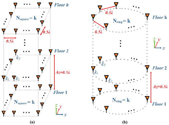
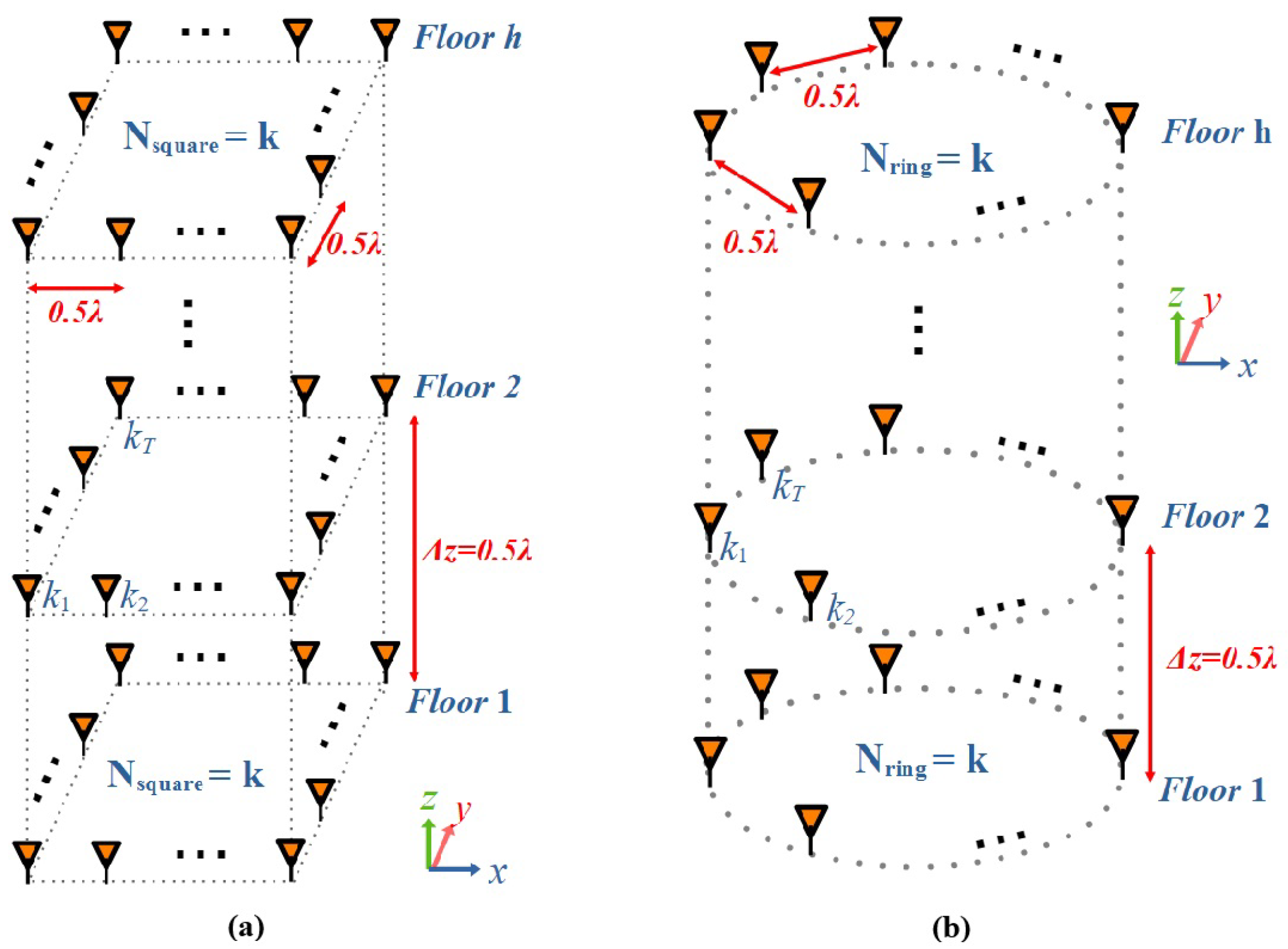
Beyond flat panels, recent studies have extended IRF modeling to volumetric 3D structures, such as Uniform Cylindrical Arrays (UCyAs) and Uniform Parallelepiped Arrays (UPaAs) shown in Figure 1. These configurations offer fuller spatial coverage and lower side-lobe cross-correlations, outperforming standard planar designs under both uniform and non-uniform distributions [10]. The 3D configurations are formed by several 2D antennas arrays stacked in z-axis, UPaA have elements distributed in square-shape on the -plane, while UCyA have elements distributed in circular-shape. The element separation distance for UPaA is , whereas in the case of UCyA, the diagonal separation between elements is , then the size of the radius (r) depends on the number of elements (k) [10]. The number of array floors is defined as h, the separation distance between floors is and the total number of antennas is defined as × h.
Figure 1.
Structure of three-dimensional antenna arrays: (a) UPaA, (b) UCyA.
2.2. Optimization Algorithms for Antenna Array Densification
Densification of antenna array and optimization of element positions usually present non-convex, multi-modal search landscapes characterized by sharp local minima. Population-based metaheuristic algorithms offer an effective path forward because they search complex spaces without requiring gradient information. Among the optimization tools applied to non-uniform array design, PSO and MVMO have proven particularly capable at determining element spacing and excitation weights [9].
PSO offers a robust population-based search strategy [14]. Originally inspired by the social behavior of bird flocking and fish schooling, the algorithm directs a swarm of candidate solutions—termed particles—through the multidimensional search space [15]. In the context of electromagnetics, PSO has been widely adopted as a benchmark technique for array geometry synthesis, successfully optimizing element positions to minimize sidelobe levels and steer radiation nulls [16]. Each particle updates its position iteratively by balancing its individual memory of the best solution found so far with the collective knowledge shared by the entire swarm.
MVMO optimizes performance through a unique statistical mapping mechanism [17]. Unlike traditional metaheuristics, MVMO dynamically builds and updates a continuous probability density function based on the mean and variance of the historically best-performing solutions [18]. This variance-guided mapping strategy has proven highly effective in antenna array synthesis problems, offering precise spatial control and accelerated convergence when tuning non-uniform element spacing [19]. A specialized mapping function then scales candidate inputs to ensure that search efforts concentrate around regions with the highest probability of yielding optimal results.
Evaluating metaheuristics on antenna layout problems reveals trade-offs between execution speed and spatial resolution. Studies examining antenna densification across non-uniform linear and planar arrays indicate that while PSO offers fast convergence in smaller search spaces, MVMO maintains higher precision when handling complex spatial constraints and dense antenna layouts. By shaping candidate updates through variance-guided mapping, MVMO achieves lower spatial correlation and reduced side-lobe levels using fewer total objective function evaluations [9].
To account for real-world spatial uncertainties in dense network deployments, stochastic programming incorporates random variables into the optimization framework [20]. Rather than relying on rigid deterministic parameters, it optimizes the expected performance across probabilistic scenarios, ensuring robust array configurations under variable operational conditions.
3. Methodology
This article presents the simulation of non-uniform three-dimensional (3D) antenna arrays in MATLAB R2024b using heuristic algorithms to optimize antenna position densification of the Non-Uniform Parallelepiped Array (NUPaA) and the Non-Uniform Cylindrical Array (NUCyA). The primary objective is to enhance the IRF of non-uniform 3D antenna arrays compared to uniform 3D configurations. By optimizing the physical array footprint while maintaining acceptable inter-user IRF levels, it is possible to improve system capacity, mitigate interference, and ease deployment constraints for advanced communication networks (such as 5G/6G) and next-generation antenna architectures (such as Gigantic MIMO).
3.1. Workflow
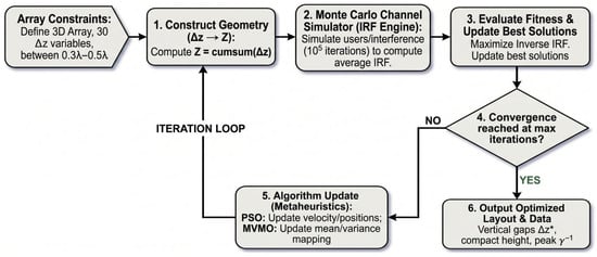
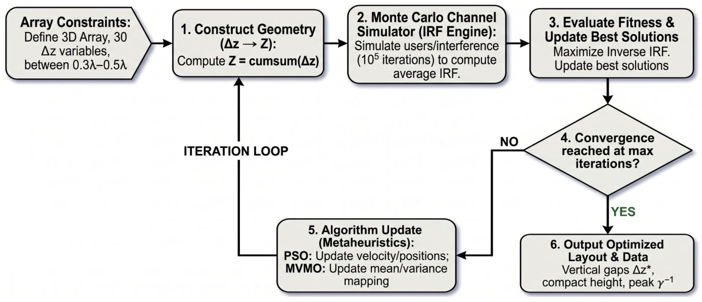
MATLAB simulation routines were developed to model uniform three-dimensional antenna arrays and calculate their corresponding IRF metrics. Stochastic programming algorithms were then applied to optimize element positioning in non-uniform 3D arrays, aiming specifically to maximize the Inverse IRF. The optimization procedure of non-uniform 3D antenna arrays is implemented through metaheuristic algorithms (PSO and MVMO) with a custom MATLAB function (IRF_cylinder for NUCyA and IRF_box for NUPaA) to identify optimal vertical floor separations () that enhance the IRF while minimizing total array height. Figure 2 shows the flow diagram for the development of optimization of MATLAB functions.
Figure 2.
Flowchart of the MATLAB functions optimization for non-uniform 3D antenna arrays. The asterisk in denotes the optimal design variable vector obtained from optimization.
3.2. Densification of Non-Uniform 3D Arrays
To optimize physical footprint efficiency without degrading spatial selectivity, a vertical non-uniform element distribution is applied to both cylindrical (NUCyA) and parallelepiped (NUPaA) structures. Unlike uniform arrays with fixed layer spacing, non-uniform topologies model inter-floor gaps via a variable vector .
Custom MATLAB routines (IRF_cylinder and IRF_box) calculate the IRF across multi-layered geometries by deriving absolute Z-axis positions through cumulative summation (). The simulation parameters span vertical elements (in steps of 5) combined with varying base geometries: radial bases (increments of 15) for NUCyA, and square bases (increments of 8) for NUPaA. To characterize spatial cross-correlation between target users and interferers, each configuration executes Monte Carlo iterations.
Monte Carlo simulations was utilized as the numerical mechanism to solve Equation (2). To make these stochastic calculations reproducible, the Pseudo-Random Number Generator (PRNG) state was initialized with a fixed seed prior to the runs. This keeps the randomly generated spatial angles for all users and interferers consistent across separate simulations, allowing researchers to replicate the fitness evaluations and optimization trajectories.
The optimization of MATLAB routines seeks to maximize the Inverse IRF () while constraining vertical inter-floor separations within physical bounds:
The upper bound of represents the standard spacing used in uniform arrays to prevent grating lobes, whereas the lower bound of acts as a threshold for physical viability. Pushing the antennas closer than this would reduce the footprint but introduce significant mutual coupling. This degrades radiation efficiency, alters input impedances and increases spatial correlation, which inevitably spawns grating lobes; then, implementing dense arrays will depend on the use of coupling networks. Despite the grating lobes, the optimization enhances beam directivity toward the user while minimizing the IRF.
3.3. Optimization Algorithms: MVMO vs. PSO
Both array topologies were evaluated across a 30-dimensional decision space () under bounded physical limits () using the MVMO and PSO algorithms. A comparative assessment reveals distinct convergence and spatial distribution dynamics:
Across both cylindrical and parallelepiped layouts, the MVMO framework exhibited a strong convergence toward physical search boundaries. The resulting geometric profiles clustered several inter-floor gaps directly at the extreme limits ( and ), combined with intermediate values such as and for NUCyA, and and for NUPaA.
In contrast to the boundary-locking behavior of MVMO, PSO produced a more continuous and homogeneous element distribution across the allowable spectrum without saturating search bounds. For NUCyA, spacing values spread fluidly across the domain (e.g., , , and ), a trend consistently mirrored in NUPaA configurations (yielding gaps such as , , and ).
It is important to note that the fitness function evaluates the average IRF over Monte Carlo iterations. An estimation of the deviation errors reveals that this massive number of iterations yields a highly stable statistical mean with a minimal standard error. The narrow standard deviation of the spatial cross-correlation confirms that the optimized configurations with the PSO and MVMO algorithms provide robust interference suppression regardless of instantaneous user locations.
4. Results and Discussion
4.1. Height Reduction of 3D Arrays
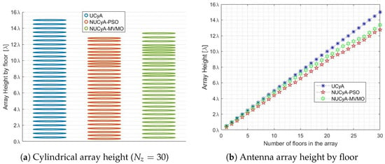
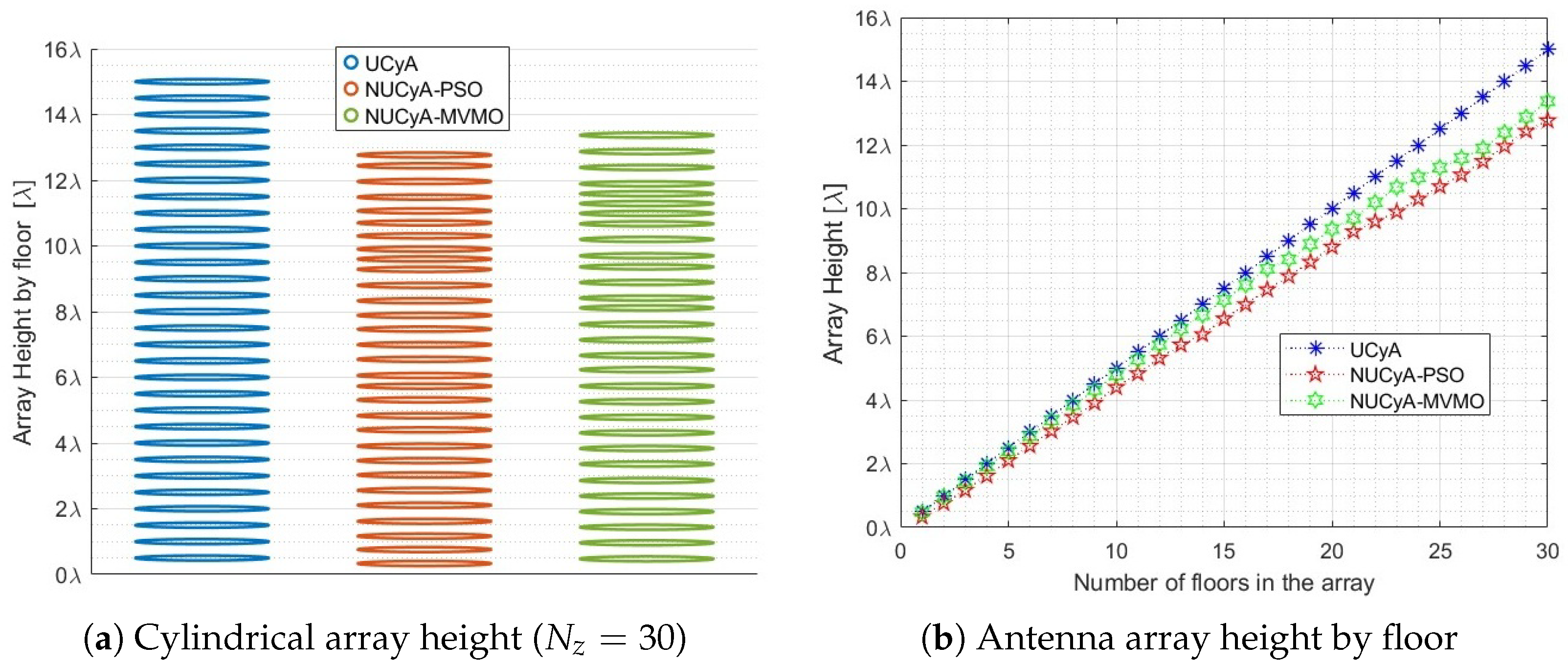
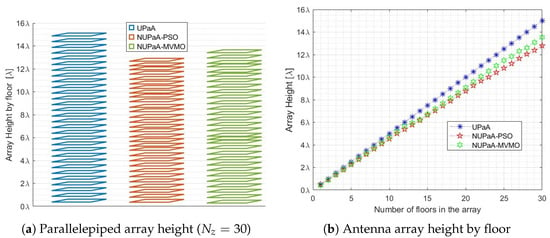
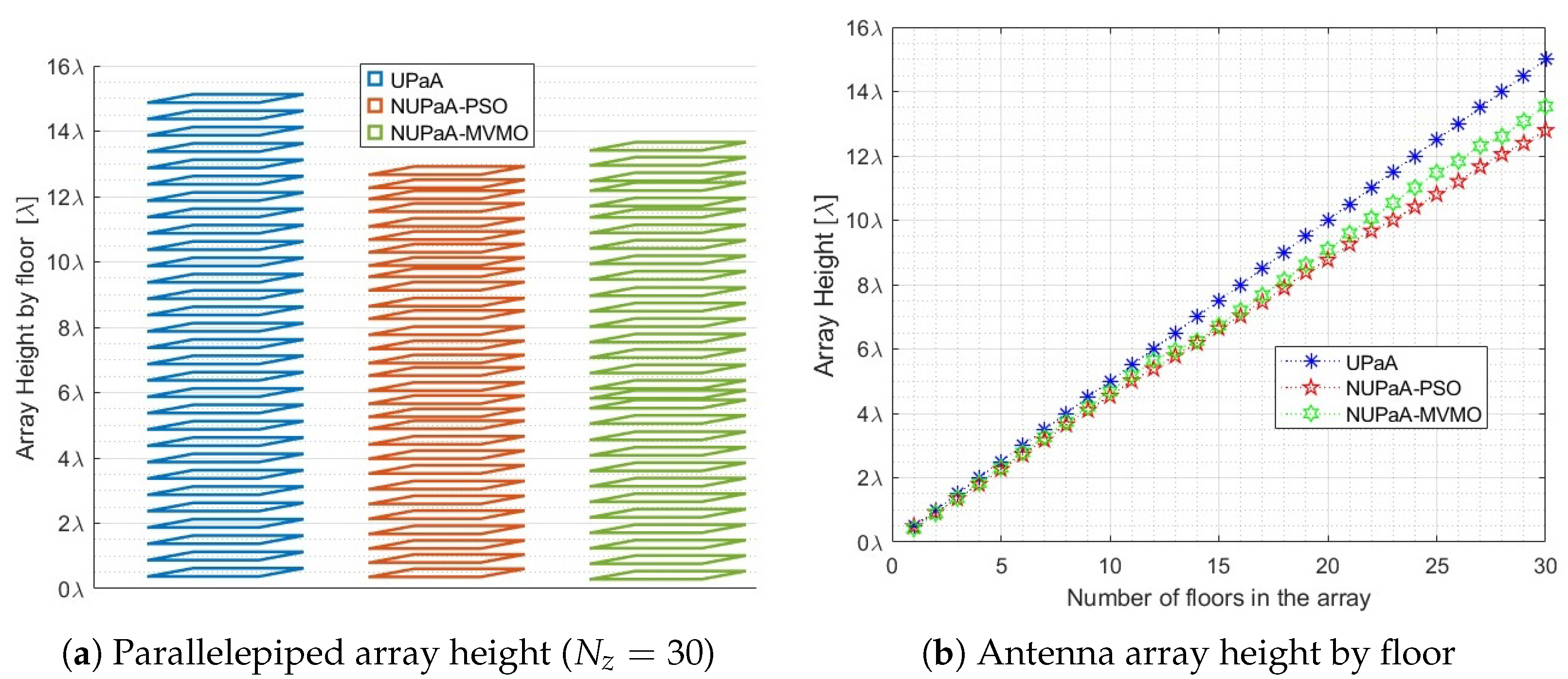
A comparative analysis between uniform structures ( height across floors) and optimized non-uniform configurations reveals vertical compression across both 3D geometries. As detailed in Figure 3a and Figure 4a, PSO achieved the highest spatial densification rate in both architectures, NUCyA-PSO compressed the cylindrical array down to ( reduction), whereas NUCyA-MVMO reached ( reduction). Similarly, NUPaA-PSO reduced the box-shaped structure to ( reduction), whereas NUPaA-MVMO attained ( reduction).
Figure 3.
Height comparison for cylindrical antenna array.
Figure 4.
Height comparison for parallelepiped antenna array.
As illustrated in Figure 3b and Figure 4b, this height reduction scaling becomes noticeable around 15 vertical floors and expands significantly beyond 20 floors. This trend confirms that vertical non-uniform densification provides a viable solution for mitigating physical footprint constraints in Massive MIMO and Gigantic MIMO deployments.
4.2. Evaluation of the Interference Reduction Factor
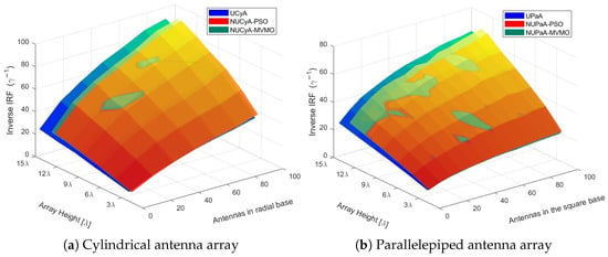
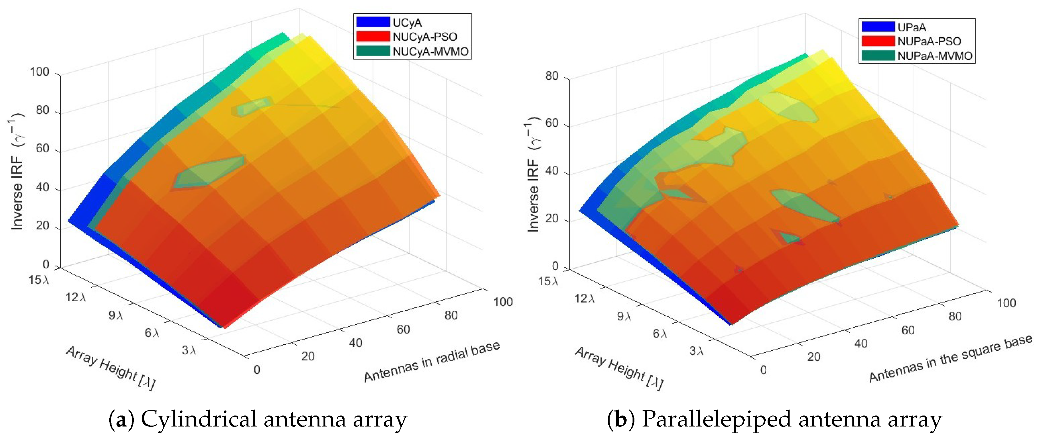
Evaluating the Inverse IRF () highlights a dual advantage: non-uniform optimization simultaneously compresses physical height and boosts spatial selectivity. For full 30-floor deployment (), both topologies operate as follows:
- Cylindrical Arrays (): The UCyA reaches at . NUCyA-PSO achieves the highest spatial selectivity (, a enhancement) at the most compact height (). NUCyA-MVMO follows closely with ( improvement) at (Figure 5a).
- Parallelepiped Arrays (): The UPaA achieves at . NUPaA-PSO yields ( enhancement) with maximum physical compaction ( height reduction). NUPaA-MVMO maximizes spatial orthogonality, attaining ( improvement) at (Figure 5b).
Figure 5.
Inverse IRF for 3D antenna arrays.
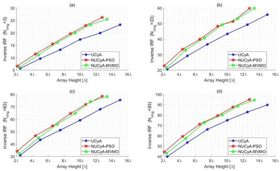
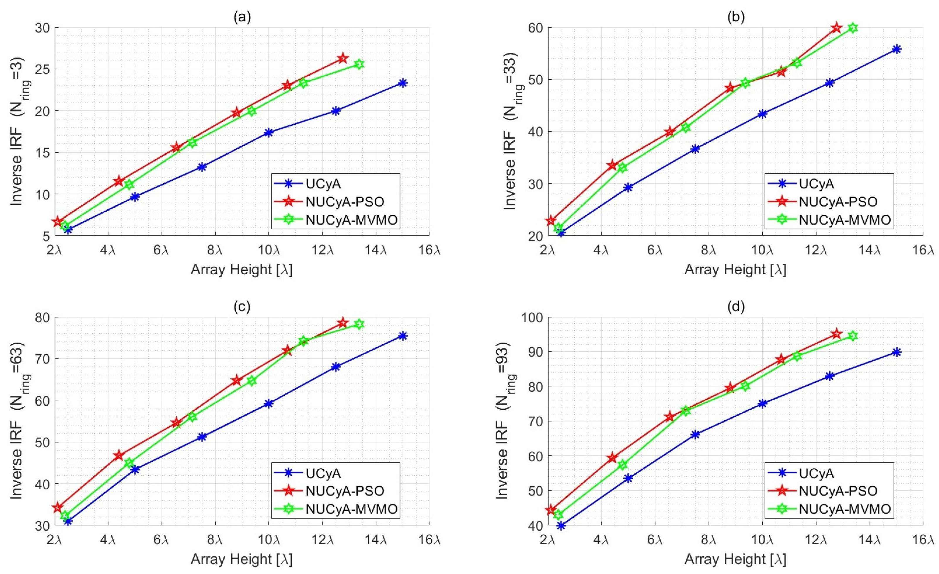
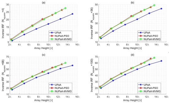
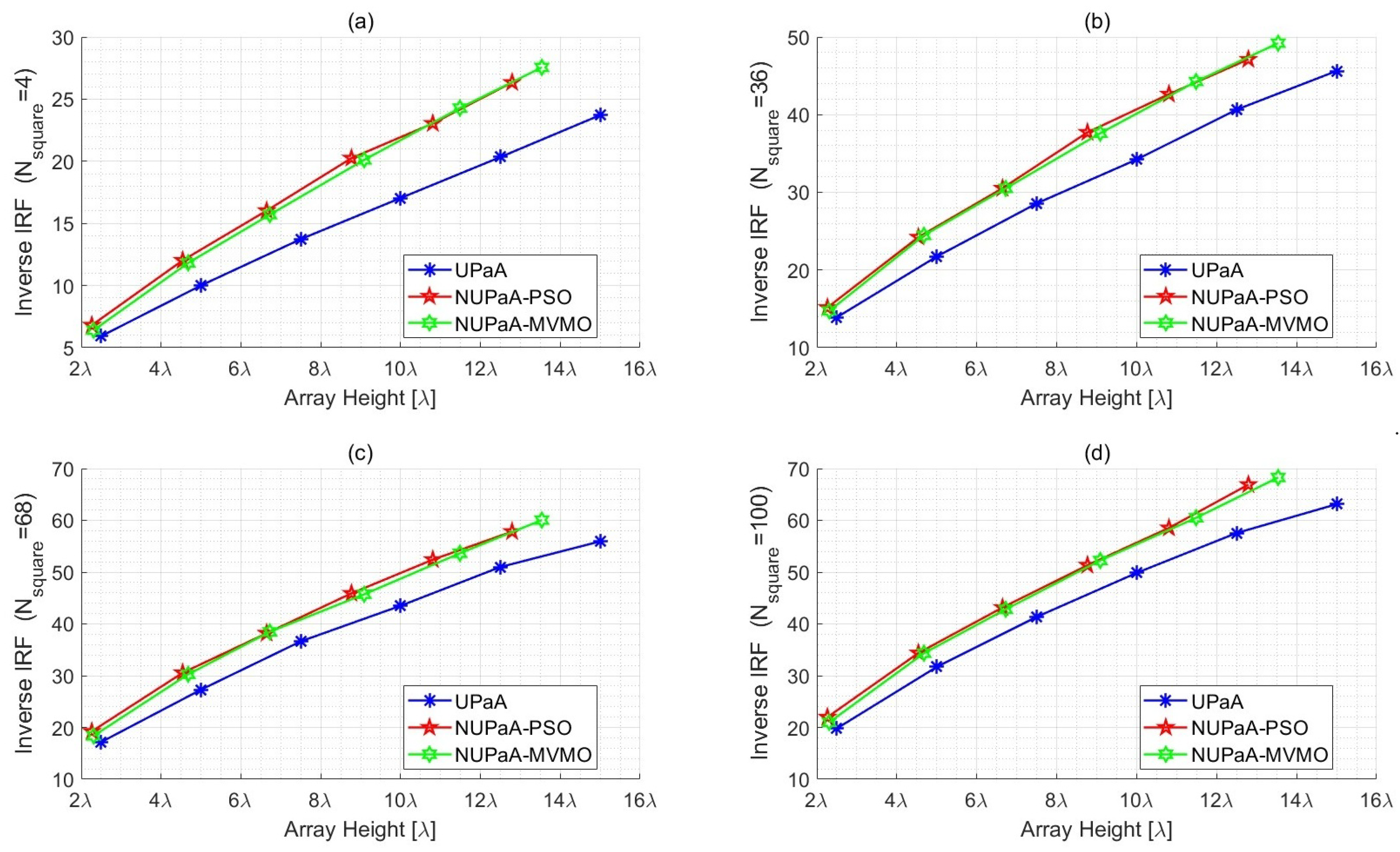
Figure 6 and Figure 7 depict the Inverse IRF as a function of physical height across scaling base elements ( and ). To fully understand the comparative advantage of the optimized non-uniform arrays, these results must be analyzed from two perspectives:
Figure 6.
Inverse IRF for cylindrical array: (a) 3, (b) 33, (c) 63, and (d) 93 antennas in radial base.
Figure 7.
Inverse IRF for parallelepiped array: (a) 4, (b) 36, (c) 68, and (d) 100 antennas in square base.
- Vertical analysis: Observing the graphs vertically at any specific array height demonstrates that the non-uniform configurations (NUCyA and NUPaA) outperform their uniform counterparts (UCyA and UPaA). For a constrained physical footprint, the optimized layouts provide higher interference reduction.
- Horizontal analysis: Observing the graphs horizontally illustrates the spatial compaction benefit. The horizontal gap between the configuration uniform curve and the optimized metaheuristic curves visually quantifies the height savings.
Furthermore, analyzing the subplots in Figure 6 and Figure 7 reveals the scalability of the non-uniform vertical optimization as the antennas in the base of the arrays increases, from simple configurations (, ) to Massive MIMO setups (, ), noting the inherent spatial selectivity increases.
However, the performance gap between the optimized non-uniform arrays and the uniform configurations is not only maintained but becomes more pronounced in denser bases. For cylindrical arrays (Figure 6), the PSO algorithm maintains a slight edge in maximizing the Inverse IRF as the number of antennas in the base increases. Meanwhile, for parallelepiped topologies (Figure 7), while PSO achieves rapid spatial compaction at lower heights, the MVMO algorithm exhibits superior capabilities at maximum array heights in heavily densified bases (e.g. ), overtaking PSO to reach the peak of spatial orthogonality.
Finally, when evaluating fixed performance targets, non-uniform densification yields spatial savings. For instance, achieving in a 93-element radial base requires in standard UCyA, whereas NUCyA topologies reach this target within – ( to height savings). Similarly, reaching in a 100-element square base demands in UPaA, but only – in NUPaA ( to height reduction).
5. Conclusions
This study aimed to evaluate the impact of element densification and non-uniform spatial distribution in three-dimensional antenna arrays on the Interference Reduction Factor (IRF) for Massive MIMO architectures. The results demonstrated that introducing variable vertical spacing via metaheuristic optimization effectively reduces the physical footprint of the arrays without degrading inter-user interference reduction. In particular, for the cylindrical topology, PSO optimization (NUCyA-PSO) compressed the total vertical span from down to (a height reduction) while improving the Inverse IRF by (), whereas MVMO (NUCyA-MVMO) achieved a height reduction () alongside a gain in Inverse IRF () compared to the uniform structure. Meanwhile, in the parallelepiped configuration, PSO (NUPaA-PSO) prioritized spatial compaction by cutting total height by () with a boost in Inverse IRF (), while MVMO (NUPaA-MVMO) favored spatial selectivity, reaching an increase in Inverse IRF () with a vertical compression (). These findings indicate that disrupting spatial array periodicities mitigates cross-correlation spikes between co-channel users, contributing actionable design guidelines to ease deployment constraints in space-limited 5G and 6G base stations. However, this study was limited by assuming idealized isotropic radiation patterns under line-of-sight (LoS) conditions and uniform angular user distributions, omitting mutual coupling dynamics and multipath fading realities. As future work, we propose extending this methodology by incorporating realistic directional element patterns with mutual coupling and implementing full 3D non-uniform placement optimization across all spatial axes ().
Author Contributions
Conceptualization, W.C. and F.L.; methodology, W.C., F.L. and D.A.; software, W.C. and F.L.; validation, F.L., M.D.-L. and D.A.; formal analysis, W.C. and F.L.; investigation, W.C.; resources, W.C. and M.D.-L.; data curation, W.C.; writing—original draft preparation, W.C.; writing—review and editing, F.L., M.D.-L. and D.A.; visualization, W.C.; supervision, F.L., M.D.-L. and D.A. All authors have read and agreed to the published version of the manuscript.
Funding
This research received no external funding.
Institutional Review Board Statement
Not applicable.
Informed Consent Statement
Not applicable.
Data Availability Statement
The data presented in this study are available on request from the corresponding author.
Conflicts of Interest
The authors declare no conflicts of interest.
References
- Larsson, E.G.; Edfors, O.; Tufvesson, F.; Marzetta, T.L. Massive MIMO for next generation wireless systems. IEEE Commun. Mag. 2014, 52, 186–195. [Google Scholar] [CrossRef] [Scilit]
- Marzetta, T.L.; Larsson, E.G.; Yang, H.; Ngo, H.Q. Fundamentals of Massive MIMO; Cambridge University Press: Cambridge, UK, 2016. [Google Scholar]
- Li, M.; Yuan, Z.; Lyu, Y.; Kyösti, P.; Zhang, J.; Fan, W. Gigantic MIMO channel characterization: Challenges and enabling solutions. IEEE Commun. Mag. 2023, 61, 126–132. [Google Scholar] [CrossRef] [Scilit]
- Marzetta, T.L. Noncooperative cellular wireless with unlimited numbers of base station antennas. IEEE Trans. Wirel. Commun. 2010, 9, 3590–3600. [Google Scholar] [CrossRef] [Scilit]
- Harris, P.; Malkowsky, S.; Vieira, J.; Tufvesson, F.; Boukley Hasan, W.; Liu, L.; Beach, M.; Armour, S.; Edfors, O. Temporal Analysis of Measured LOS Massive MIMO Channels with Mobility. In Proceedings of the 2017 IEEE 85th Vehicular Technology Conference (VTC Spring), Sydney, Australia, 4–7 June 2017; pp. 1–5. [Google Scholar]
- Shafi, M.; Molisch, A.F.; Smith, P.J.; Haustein, T.; Kou, P.; Benjebbour, A.; Kasai, R.; Zhang, J.; de Silva, S.; Tufvesson, F. 5G: A tutorial overview of standards, trials, challenges, deployment, and practice. IEEE J. Sel. Areas Commun. 2017, 35, 1201–1221. [Google Scholar] [CrossRef] [Scilit]
- Rusek, F.; Persson, D.; Lau, B.K.; Larsson, E.G.; Marzetta, T.L.; Edfors, O.; Tufvesson, F. Scaling up MIMO: Opportunities and challenges with very large arrays. IEEE Signal Process. Mag. 2013, 30, 40–60. [Google Scholar] [CrossRef] [Scilit]
- Altamirano, C.D.; De Almeida, C. Inter-user interference reduction in massive MIMO for linear and planar arrays. Int. J. Commun. Antenna Propag. 2019, 9, 68–76. [Google Scholar] [CrossRef] [Scilit]
- Lara, M.F.; Altamirano, C.D.; Cepeda, J.; Grijalva, F. Antenna Densification in Non-uniform Linear and Planar Arrays. In Lecture Notes in Networks and Systems; Springer: Cham, Switzerland, 2024; pp. 93–104. [Google Scholar]
- Lara, M.F.; Altamirano, C.D.; Narváez, A.R.; Grijalva, F.; Molina, H.B. Interference Reduction Factor Evaluation for Cylindrical and Parallelepiped Antenna Arrays in Massive MIMO Systems. In Proceedings of the 2024 IEEE Colombian Conference on Communications and Computing (COLCOM), Bogota, Colombia, 13–15 August 2024; pp. 1–5. [Google Scholar]
- Li, X.; Li, L.; Xie, L.; Su, X.; Zhang, P. Performance analysis of 3D massive MIMO cellular systems with collaborative base station. Int. J. Antennas Propag. 2014, 2014, 614061. [Google Scholar] [CrossRef] [Scilit]
- Gao, X.; Edfors, O.; Rusek, F.; Tufvesson, F. Massive MIMO performance evaluation based on measured propagation data. IEEE Trans. Wirel. Commun. 2015, 14, 3899–3911. [Google Scholar] [CrossRef] [Scilit]
- Altamirano, C.D.; De Almeida, C. Inter-user interference reduction factor for 3-D massive MIMO systems. In Proceedings of the 2016 8th IEEE Latin-American Conference on Communications (LATINCOM), Medellin, Colombia, 16–18 November 2016; pp. 1–6. [Google Scholar]
- Kennedy, J.; Eberhart, R. Particle swarm optimization. In Proceedings of the IEEE International Conference on Neural Networks, Perth, Australia, 27 November–1 December 1995; Volume 4, pp. 1942–1948. [Google Scholar]
- Shi, Y.; Eberhart, R.C. A modified particle swarm optimizer. In Proceedings of the 1998 IEEE International Conference on Evolutionary Computation (ICEC), Anchorage, AK, USA, 4–9 May 1998; pp. 69–73. [Google Scholar]
- Khodier, M.M.; Christodoulou, C.G. Linear array geometry synthesis with minimum sidelobe level and null control using particle swarm optimization. IEEE Trans. Antennas Propag. 2005, 53, 2674–2679. [Google Scholar] [CrossRef] [Scilit]
- Erlich, I.; Rueda, J.L.; Wildenhues, S. Mean-variance mapping optimization algorithm for solving power system problems. In Proceedings of the 2010 IEEE Power and Energy Society General Meeting, Minneapolis, MN, USA, 25–29 July 2010; pp. 1–8. [Google Scholar]
- Erlich, I.; Shewarega, F.; Rueda, J.L. Application of mean-variance mapping optimization to power system identification and control tuning. IEEE Trans. Power Syst. 2014, 29, 3034–3043. [Google Scholar]
- Guney, K.; Basbug, S. Linear antenna array synthesis using mean variance mapping method. Electromagnetics 2014, 34, 67–84. [Google Scholar] [CrossRef] [Scilit]
- Ravindran, A.; Ragsdell, K.M.; Reklaitis, G.V. Engineering Optimization: Methods and Applications, 2nd ed.; John Wiley & Sons: Hoboken, NJ, USA, 2006. [Google Scholar]
Disclaimer/Publisher’s Note: The statements, opinions and data contained in all publications are solely those of the individual author(s) and contributor(s) and not of MDPI and/or the editor(s). MDPI and/or the editor(s) disclaim responsibility for any injury to people or property resulting from any ideas, methods, instructions or products referred to in the content. |
© 2026 by the authors. Licensee MDPI, Basel, Switzerland. This article is an open access article distributed under the terms and conditions of the Creative Commons Attribution (CC BY) license.