


Abstract
This paper investigates the effect of iterated-integral action on PID control of time-delay systems through frequency- and time-domain analyses. Successive integral stages are evaluated in terms of transient performance, stability margins, and disturbance rejection under reference-change and disturbance scenarios. Results show that iterated-integral action reduces overshoot and improves steady-state accuracy while maintaining acceptable settling times. Most performance improvement comes from the first additional stage, whereas subsequent stages provide marginal benefits while increasing phase lag. These findings provide practical guidelines for incorporating iterated-integral action into PID controllers while balancing performance and robustness.
1. Introduction
Proportional–Integral–Derivative (PID) control remains widely used in industrial automation because of its simplicity, low computational cost, and ease of implementation [1]. However, controlling processes with significant time delays remains challenging. Since the effect of a control action is not immediately reflected in the measured output, the error may persist and accumulate, leading to excessive integral action, increased overshoot, and degraded transient performance [1,2]. These effects are particularly relevant in process-control applications, where slow dynamics and transport delays are common. Although advanced solutions such as Smith predictors, adaptive tuning, and Internal Model Control (IMC) can address these limitations, they generally require process models or more complex tuning procedures [3,4].
In this context, iterated-integral action extends the conventional PID structure through additional nested integral stages, potentially improving transient performance and disturbance rejection [5,6]. However, these stages also introduce phase lag, requiring a balance between performance and robustness. Although used in advanced control architectures, their effect within conventional PID controllers for time-delay systems remains insufficiently studied.
This paper investigates iterated-integral action in PID control of time-delay systems. Three tuning configurations are analyzed in the frequency and time domains to assess their effects on stability, transient performance, and disturbance rejection, providing practical guidelines for balancing performance and robustness.
2. Iterated Integral Terms in PID Control
This section introduces iterated-integral action and its incorporation into PID controllers. The theoretical formulation is presented alongside the generalized PID structure used to analyze the effects of successive integral stages.
2.1. Fundamentals of Iterated Integral Terms
Integral action plays a key role in control systems by eliminating steady-state errors caused by disturbances or modeling uncertainties. The standard integral term for a PID controller in continuous time is defined as
where is the tracking error and is the integral gain.
In process control applications, particularly those involving slow dynamics, long time delays, or actuator limitations, the use of iterated integral termsprovides an alternative way to distribute the integral action. Instead of relying on a single integral term, the corrective action can be expressed through successive nested integrations of the error signal.
An iterated integral in control is defined as a sequence of recursive integrations. The first integral term is given by
and higher-order iterated integrals are defined recursively as
where each represents a successive nested integration of the tracking error .
The proposed formulation distributes the integral action across successive stages rather than concentrating it in a single term. Each iterated-integral stage introduces an additional pole at the origin, increasing the system type and improving steady-state tracking and disturbance rejection. However, successive stages also increase phase lag, making careful gain selection essential to preserve robustness.
2.2. PID Formulation with Iterated Integral Terms
Based on the iterated integral formulation introduced in the previous subsection, the PID control law can be extended to include multiple integral stages.
The conventional PID controller is given by
where , , and are the proportional, integral, and derivative gains, and is the tracking error, with being the reference signal and the process output [1,7].
To improve performance, the integral action can be extended using iterated-integral terms [5], yielding the generalized control law.
where is the base integral gain of the conventional PID controller; is the conventional integral term; represents the successive iterated-integral terms; is the weighting gain associated with each additional stage; and is the total number of integral stages.
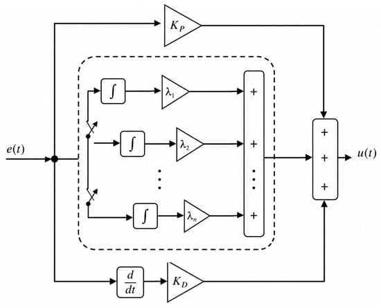
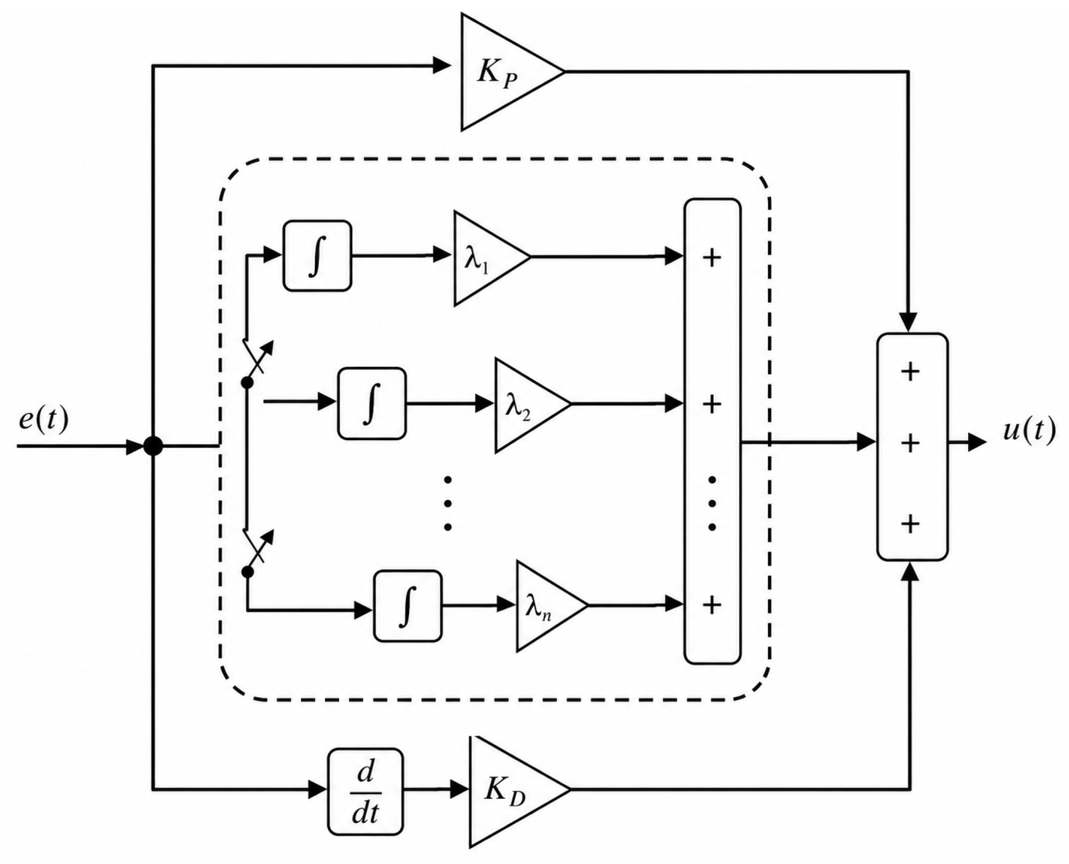
Figure 1 illustrates the PID controller with iterated-integral action, where the additional stages distribute the integral action to improve disturbance rejection.
Figure 1.
PID Structure of the Proposed Iterated-Integral PID Controller.
The inclusion of iterated-integral stages can improve steady-state tracking and disturbance rejection but also increases phase lag. Therefore, the weighting gains associated with successive additional stages, , should be kept small to preserve closed-loop robustness while benefiting from the additional integral action.
3. Results
This section tests and evaluates the proposed control approach. To assess the controller’s performance, we consider a linear system with a long time-delay characteristic [7]. The system is simulated and analyzed in Simulink under varying reference inputs and disturbance conditions.
3.1. High-Order Linear System
This numerical example was previously studied by [7], and its transfer function is presented below:
The system represented in Equation (6) can be approximated by an FOPDT model using the reaction curve method [1] as follows:
The normalized dead time, , is a widely used indicator of process control difficulty [2,8]. Since values approaching one indicate increasingly significant dead time, this value represents a challenging control scenario for evaluating the effect of iterated-integral action.
3.2. Tuning Configurations
Throughout the study, three tuning configurations were investigated to compare the conventional PID controller with the proposed iterated-integral approach and to evaluate the influence of the iterated-integral parameters on performance and stability:
- Case 1: Reference configuration, with a 30% increase in the original and a slight adjustment (3–5%) of at each iterated stage.
- Case 2: The first iterated-integral weighting gain () was reduced from 0.1 to 0.001 to improve the stability margins.
- Case 3: Based on Case 2, the original was increased by 50% to evaluate performance close to the stability limit.
For each tuning configuration, the effect of progressively adding up to four iterated-integral stages was evaluated against the baseline PID controller. To complement the time-domain simulations, a Bode analysis was performed to assess the corresponding gain and phase margins. The results are summarized in Table 1.
Table 1.
Frequency-domain results for the three tuning configurations.
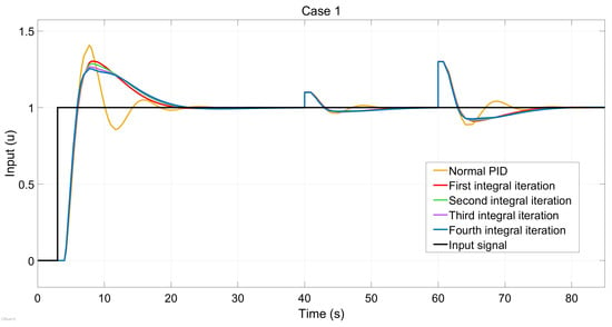
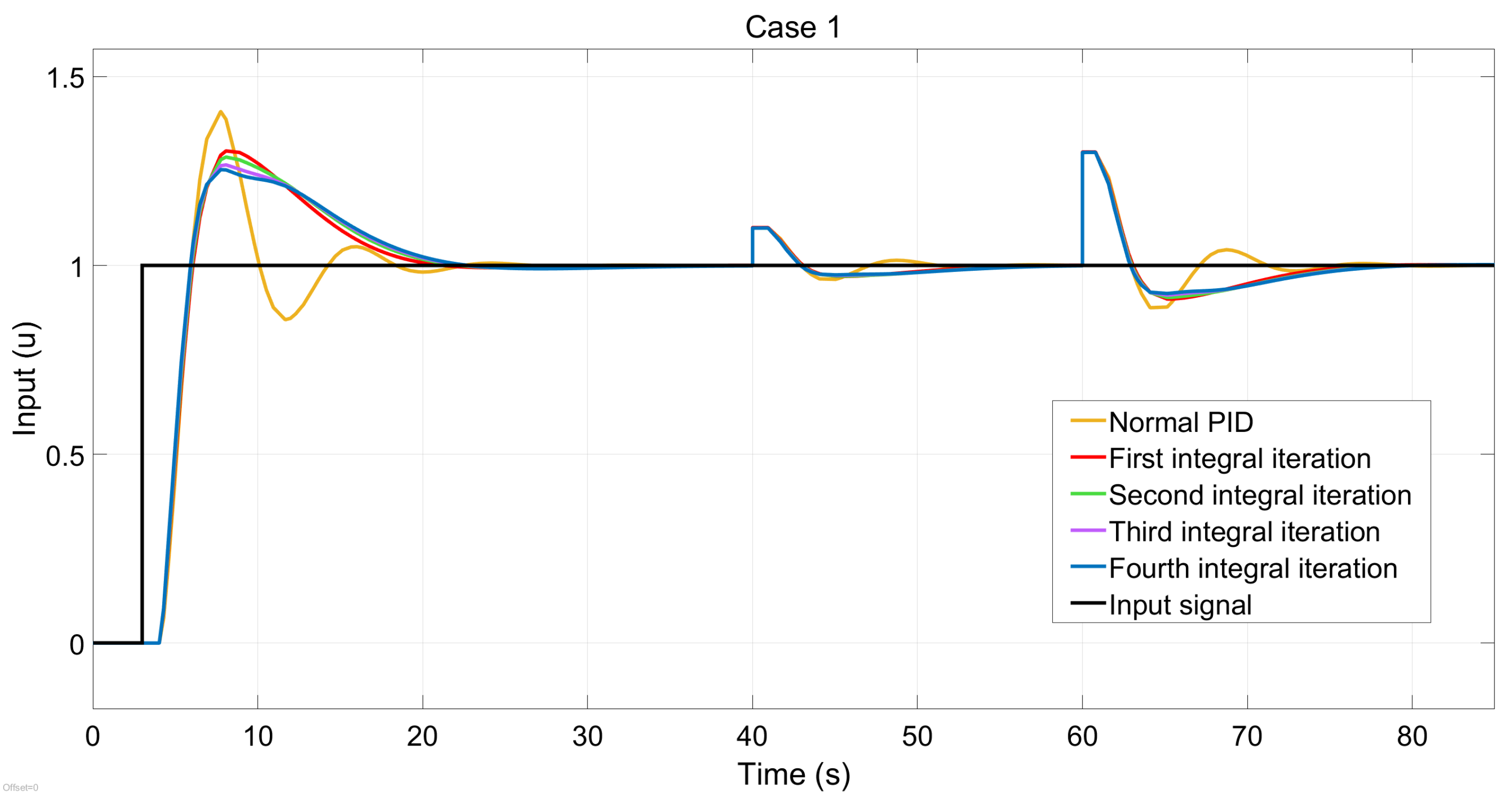
Table 1 summarizes the frequency-domain results for the three tuning configurations. In all cases, introducing the first iterated-integral stage yields the largest improvement in phase margin, whereas subsequent stages provide progressively smaller gains and gradually reduce the gain margin. This behavior indicates diminishing returns as additional iterated-integral stages are incorporated. Among the three configurations, Case 1, Figure 2, achieves the highest gain margin, whereas Cases 2 and 3 provide substantially larger phase margins due to the reduction of . Overall, Case 2 offers the best compromise between robustness and transient performance, while the fourth-stage configuration in Case 3 operates closest to the stability boundary.
Figure 2.
Complete simulation results for Case 1.
3.3. Time Simulation Results
A complete simulation was performed for each case, including a 100% reference change (0 to 1) at s and two step disturbances of 10% and 30% applied at s and s, respectively, representing moderate and severe load changes.
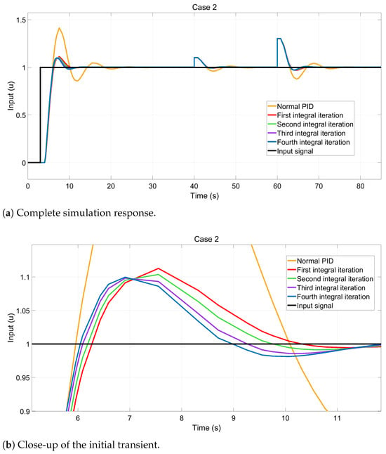
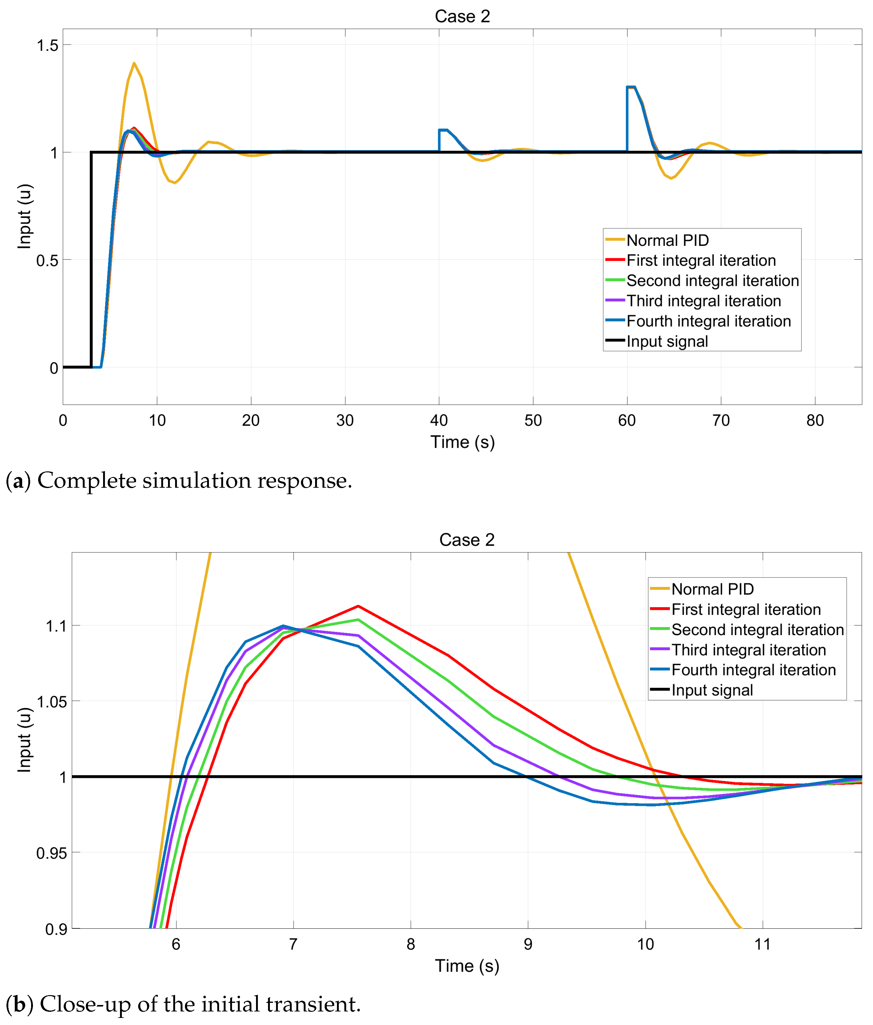
These findings confirm that the first iterated-integral stage provides the largest improvement in transient performance. While additional iterated-integral stages continue to reduce the overshoot and settling time, the incremental benefit decreases with each added stage, indicating diminishing returns. Reducing the first iterated-integral weighting gain, , from 0.1 to 0.001 further improves the transient response while preserving closed-loop stability, explaining the superior performance of Case 2, Figure 3a,b, over the reference configuration.
Figure 3.
Simulation results for Case 2. (a) Complete closed-loop response. (b) Close-up of the initial transient highlighting the reduction in overshoot obtained by decreasing the first iterated-integral weighting gain.
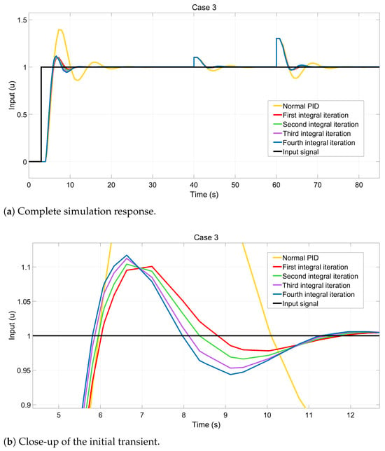
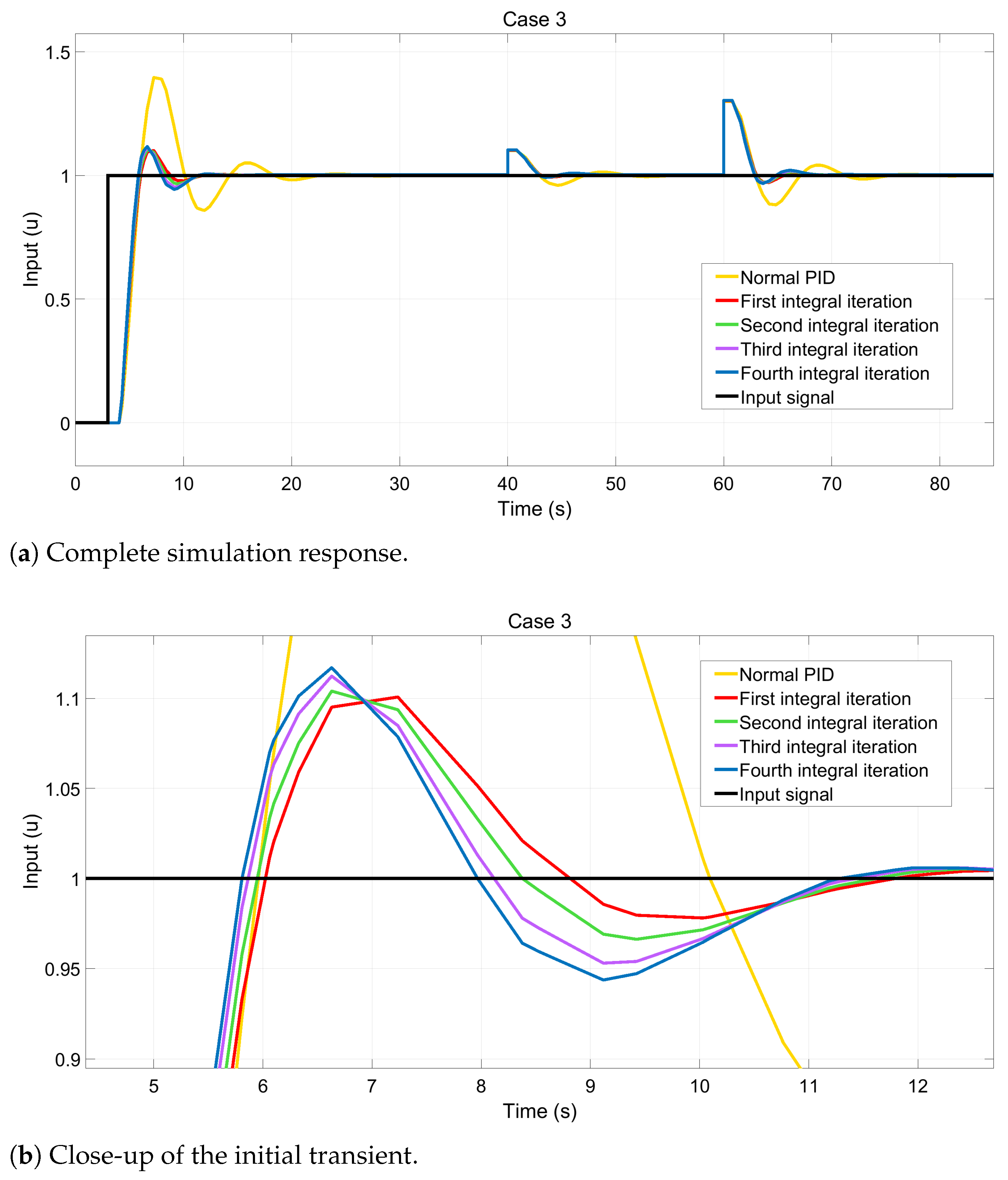
Case 3, Figure 4a,b, was introduced to investigate the effect of increasing the controller aggressiveness by restoring the original integral gain, , while maintaining the tuning strategy of Case 2. As expected, the response became faster but exhibited larger overshoot and increased oscillatory behavior. Although the third and fourth iterated-integral stages further reduce the overshoot and settling time, the corresponding improvements are only marginal. These results indicate that increasing the controller aggressiveness beyond the tuning adopted in Case 2 provides only limited additional improvement in transient performance.
Figure 4.
Simulation results for Case 3. (a) Complete closed-loop response. (b) Close-up of the initial transient illustrating the faster response, increased overshoot, and oscillatory behavior as the controller operates closer to the stability boundary.
The latter is negligible in most applications, as the fourth iterated-integral stage yields a steady-state error of less than 0.01% of the reference. Meanwhile, the transient response shows increased overshoot and oscillations, reflecting a faster but less-damped response. This aligns with frequency-domain analysis, which indicates a reduction in gain margin as controller aggressiveness rises. As a result, oscillations during reference-change and disturbance-rejection tests are larger than in Case 2.
3.4. Performance Analysis
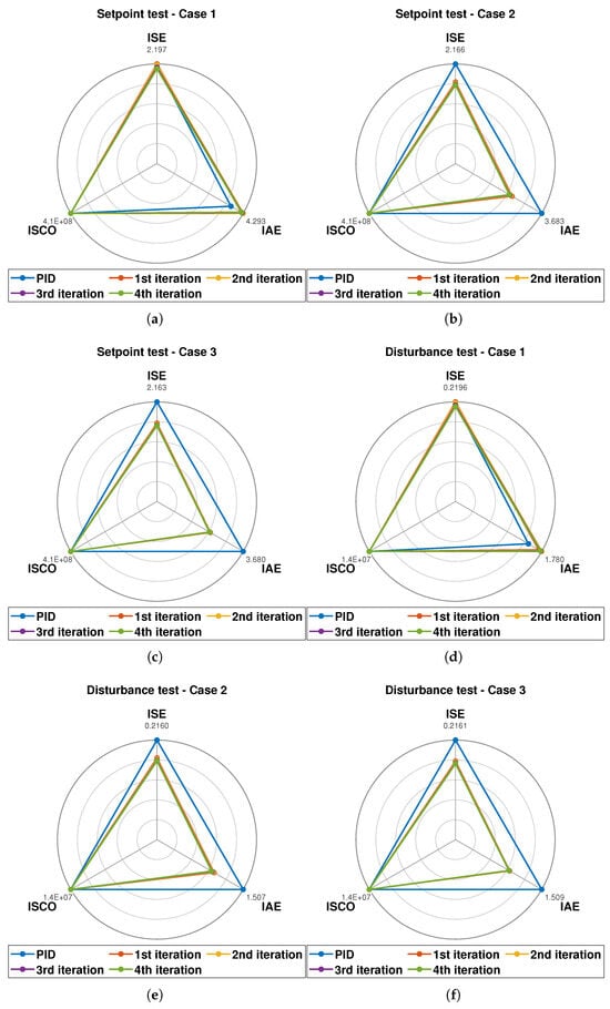
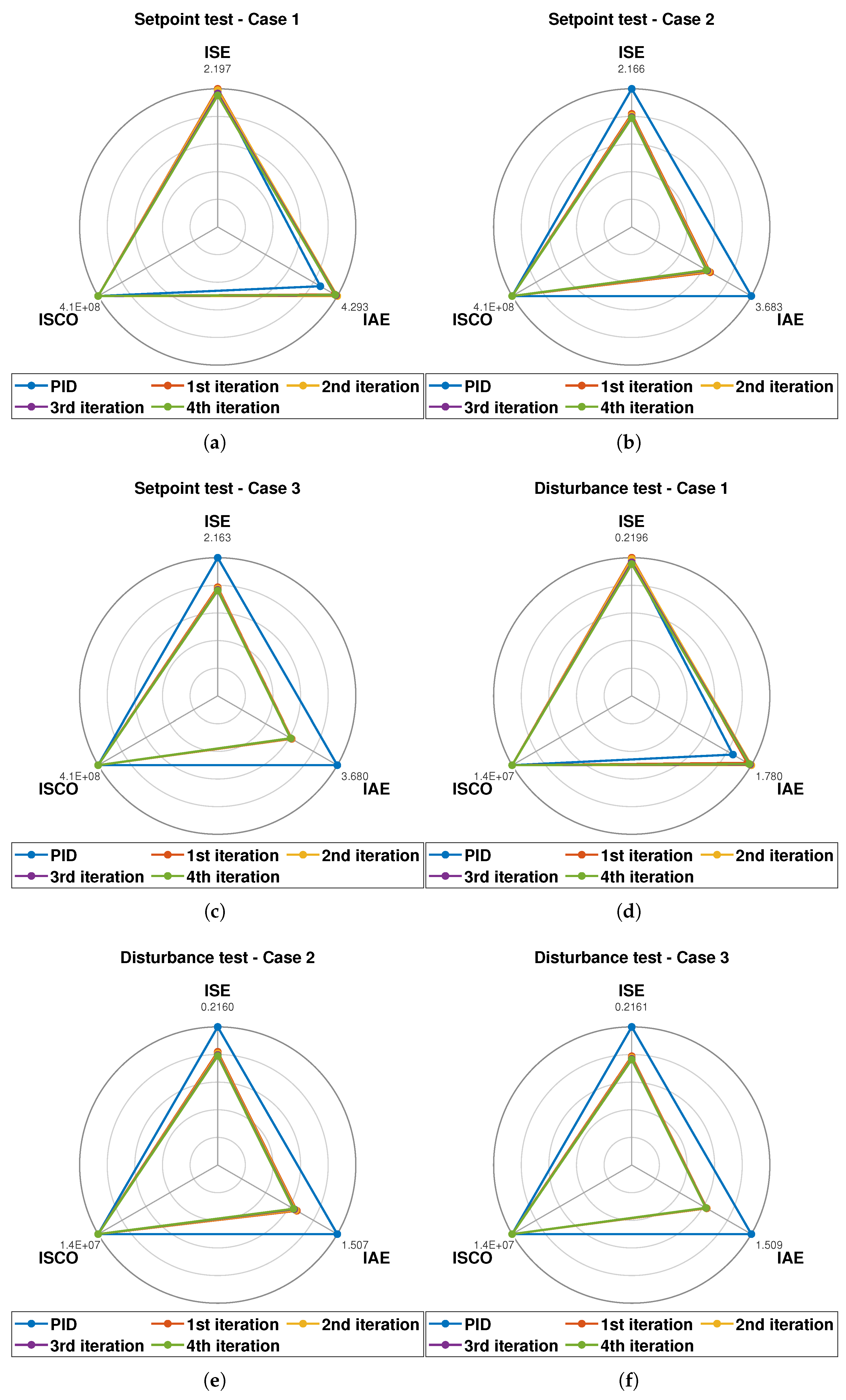
We selected the Integral Absolute Error (IAE), Integral Squared Error (ISE), and Integral Squared Control Output (ISCO) as performance indices. Reference-change and disturbance events were simulated separately, and the corresponding indices were calculated for each case. The results are presented in Figure 5 according to case and test type.
Figure 5.
Spider diagrams for the three tuning configurations under Setpoint change and disturbance-test conditions: (a–c) setpoint change; (d–f) disturbance test.
The results show that the first iterated-integral stage provides most of the achievable performance improvement. While Case 1 reduces overshoot, its larger IAE and ISE values indicate a more persistent transient error. Cases 2 and 3 reduce both indices, whereas additional iterated-integral stages provide only marginal improvements. In contrast, ISCO remains nearly unchanged across the evaluated configurations, indicating that the improved tracking performance is achieved without a significant increase in control effort.
3.5. Practical Guidelines for Controller Design
Based on the analysis, practical guidelines for incorporating iterated-integral action into PID controllers can be established. A single additional integral stage provides most of the performance improvement, whereas higher-order stages offer diminishing returns while increasing phase lag. Therefore, the contribution of successive iterated-integral stages should be progressively reduced to preserve closed-loop robustness. Overall, iterated-integral action can enhance PID performance in time-delay systems without sacrificing controller simplicity.
4. Conclusions
This paper investigated the effect of incorporating iterated-integral action into PID controllers for time-delay systems through frequency- and time-domain analyses. The results show that iterated-integral action can improve transient performance and disturbance rejection while preserving the simplicity of the classical PID structure. The analysis further reveals that the first additional iterated-integral stage provides most of the achievable performance improvement, whereas subsequent stages offer only marginal benefits and increase phase lag. Consequently, weighting gains for additional iterated-integral stages should be carefully scaled to preserve closed-loop robustness. Overall, this study provides practical guidelines for incorporating iterated-integral action into PID controllers for time-delay systems. Future work will address systematic tuning methods, nonlinear processes, more complex disturbance profiles, and experimental validation.
Author Contributions
Conceptualization, J.R. and O.C.; methodology, J.R.; software, J.R.; validation, J.R. and O.C.; formal analysis, J.R.; investigation, J.R.; resources, O.C.; data curation, J.R.; writing—original draft preparation, J.R.; writing—review and editing, O.C.; visualization, J.R.; supervision, O.C.; project administration, O.C.; funding acquisition, O.C. All authors have read and agreed to the published version of the manuscript.
Funding
This research was funded by the Universidad San Francisco de Quito through the Poli-Grants Program under Grant number 41983.
Institutional Review Board Statement
Not applicable.
Informed Consent Statement
Not applicable.
Data Availability Statement
The data supporting the findings of this study (Simulink simulation files and processed results) are available from the corresponding author upon reasonable request.
Acknowledgments
The authors gratefully acknowledge the Universidad San Francisco de Quito for supporting this work through the Poli-Grants Program.
Conflicts of Interest
The authors declare no conflicts of interest. The funders had no role in the design of the study; in the collection, analysis, or interpretation of data; in the writing of the manuscript; or in the decision to publish the results.
References
- Liptak, B.G.; Piovoso, M.J.; Shinskey, F.G.; Eren, H.; Totherow, G.K.; Jamison, J.E.; Morgan, D.; Hertanu, H.I.; Marszal, E.M.; Berge, J.; et al. Instrument Engineers’ Handbook, Volume two: Process Control and Optimization; CRC Press: Boca Raton, FL, USA, 2018. [Google Scholar]
- Normey-Rico, J.E.; Santos, T.L.; Flesch, R.C.; Torrico, B.C. Control of dead-time process: From the Smith predictor to general multi-input multi-output dead-time compensators. Front. Control Eng. 2022, 3, 953768. [Google Scholar] [CrossRef] [Scilit]
- Albertos, P.; Luan, X.; Garcia, P. Smith predictor based control of multi time-delay processes. Annu. Rev. Control 2025, 60, 101008. [Google Scholar] [CrossRef] [Scilit]
- Nath, U.M.; Dey, C.; Mudi, R.K. Review on IMC-based PID controller design approach with experimental validations. IETE J. Res. 2023, 69, 1640–1660. [Google Scholar] [CrossRef] [Scilit]
- Camacho, O.; Vega, S.; Herrera, M.; Benitez, D.; Gude, J.J. Hybrid Sliding Mode Control for Dominant Dead-Time Systems Based on a Sliding Surface with Iterated Integral Terms. In Proceedings of the 23rd European Control Conference (ECC), Thessaloniki, Greece, 24–27 June 2025; IEEE-IFAC: Laxenburg, Austria, 2025; pp. 1714–1719. [Google Scholar]
- Herrera, M.; Camacho, O.; Prado-Romo, A.J. A model-free dynamic sliding mode control approach with iterated-integral terms on sliding surface for chemical processes. Control Eng. Pract. 2026, 170, 106821. [Google Scholar] [CrossRef] [Scilit]
- Sardella, M.F.; Serrano, M.E.; Camacho, O.; Scaglia, G.J. Design and application of a linear algebra based controller from a reduced-order model for regulation and tracking of chemical processes under uncertainties. Ind. Eng. Chem. Res. 2019, 58, 15222–15231. [Google Scholar] [CrossRef] [Scilit]
- Astrom, K.J.; Hägglund, T. Advanced PID control. IEEE Control Syst. 2006, 26, 98–101. [Google Scholar] [CrossRef]

Disclaimer/Publisher’s Note: The statements, opinions and data contained in all publications are solely those of the individual author(s) and contributor(s) and not of MDPI and/or the editor(s). MDPI and/or the editor(s) disclaim responsibility for any injury to people or property resulting from any ideas, methods, instructions or products referred to in the content. |
© 2026 by the authors. Licensee MDPI, Basel, Switzerland. This article is an open access article distributed under the terms and conditions of the Creative Commons Attribution (CC BY) license.