


Abstract
This study presents a 3D-printed prosthetic sole with a flexible toe segment for a bionic lower-limb prosthesis. The design exploits functional material distribution: a load-bearing frame in carbon-filled nylon (PAHT-CF) is combined with a thermoplastic polyurethane (TPU 95A) zone that acts as a passive elastic hinge. Static finite element analysis in SolidWorks Simulation under a 400 N vertical load yields a tip displacement of about 25 mm and a toe-segment deformation near 10 mm. Compression testing on a hydraulic press up to 1000 N produces a peak displacement of around 7 mm without fracture or residual plastic deformation, confirming the suitability of the PAHT-CF/TPU hybrid for low-cost prosthetic feet.
1. Introduction
Lower-limb amputation remains a significant medical, social, and engineering challenge because it directly affects mobility, independence, employability, and overall quality of life. According to the World Health Organization, approximately 2.4 billion people worldwide require rehabilitation services, and this demand continues to increase because of population aging and the spread of chronic diseases [1]. Assistive technologies, including lower-limb prostheses, play an important role in restoring mobility and supporting social inclusion. However, access to high-quality prosthetic devices remains limited because of high production costs, insufficient infrastructure, and restricted availability of specialized rehabilitation services [2,3].
The prosthetic foot is one of the most critical components of a lower-limb prosthesis. It provides impact absorption, load transfer, stability, rollover support, and push-off during walking. Conventional rigid prosthetic feet often fail to reproduce natural forefoot biomechanics, which may increase joint loading and reduce gait comfort. In particular, the toe segment significantly influences rollover smoothness, energy transfer, and push-off efficiency during gait [4,5].
Recent advances in additive manufacturing have enabled the development of lightweight prosthetic structures with controlled stiffness, complex internal geometries, and individualized mechanical behavior. Flexible forefoot zones produced using compliant materials and lattice structures demonstrate strong potential for improving prosthetic-foot biomechanics while maintaining low manufacturing complexity [6].
This study aims to develop and experimentally evaluate a 3D-printed prosthetic sole with a flexible toe segment capable of controlled elastic deformation under load. The proposed concept combines a rigid PAHT-CF load-bearing structure with an internal TPU 95A-compliant zone to achieve passive forefoot flexibility without mechanical hinges. This work includes literature analysis, material selection, CAD development, numerical simulation, prototype fabrication, and experimental validation under compressive loading.
The scientific novelty of the proposed design lies in the hybrid integration of rigid and compliant materials within a single prosthetic-foot architecture. Unlike conventional rigid feet or articulated mechanisms, the developed concept achieves controlled toe-segment bending through structural geometry and elastic material behavior.
2. Review of Existing Scientific Solutions for Prosthetic Feet
The first stage of this study involved an analytical review of publications on prosthetic foot design, energy-storage-and-return (ESAR) constructions, additive manufacturing technologies, and compliant forefoot elements. This review aimed to identify design approaches applicable to a prosthetic sole featuring a flexible toe segment that ensures cushioning, controlled deformation, and energy return during the push-off phase.
Recent studies indicate that ESAR constructions represent one of the most promising directions in prosthetic foot development. ESAR feet store part of the energy applied during the stance phase and release it in late stance, thereby improving gait efficiency and reducing the user’s metabolic cost. Keel and heel stiffness govern the deformation pattern, range of motion, stability, and the magnitude of returned energy [7,8].
Adjustable stiffness is also significant. Modifying the stiffness of the forefoot and heel zones substantially affects gait biomechanics. Insufficient stiffness can improve compliance and increase the range of motion, but excessive softening reduces mechanical efficiency and degrades push-off force transmission. A rational balance between strength, flexibility, and energy return is therefore essential when designing a prosthetic sole [8].
Additive manufacturing has attracted growing attention for prosthetic foot fabrication. 3D printing accelerates prototyping, enables individualized geometry, and tunes mechanical properties through shape, internal structure, and material choice. The technology is particularly attractive for complex lattice and compliant structures that are difficult to produce by conventional methods [7,9].
Modular and low-cost prosthetic feet form another important branch of research. Such concepts allow for component-level stiffness tuning—for example, of the toe section—through interchangeable elastic elements. This adaptability lets the foot be matched to different operating conditions, user mass, activity level, and gait patterns [10].
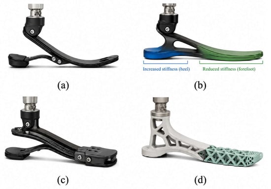
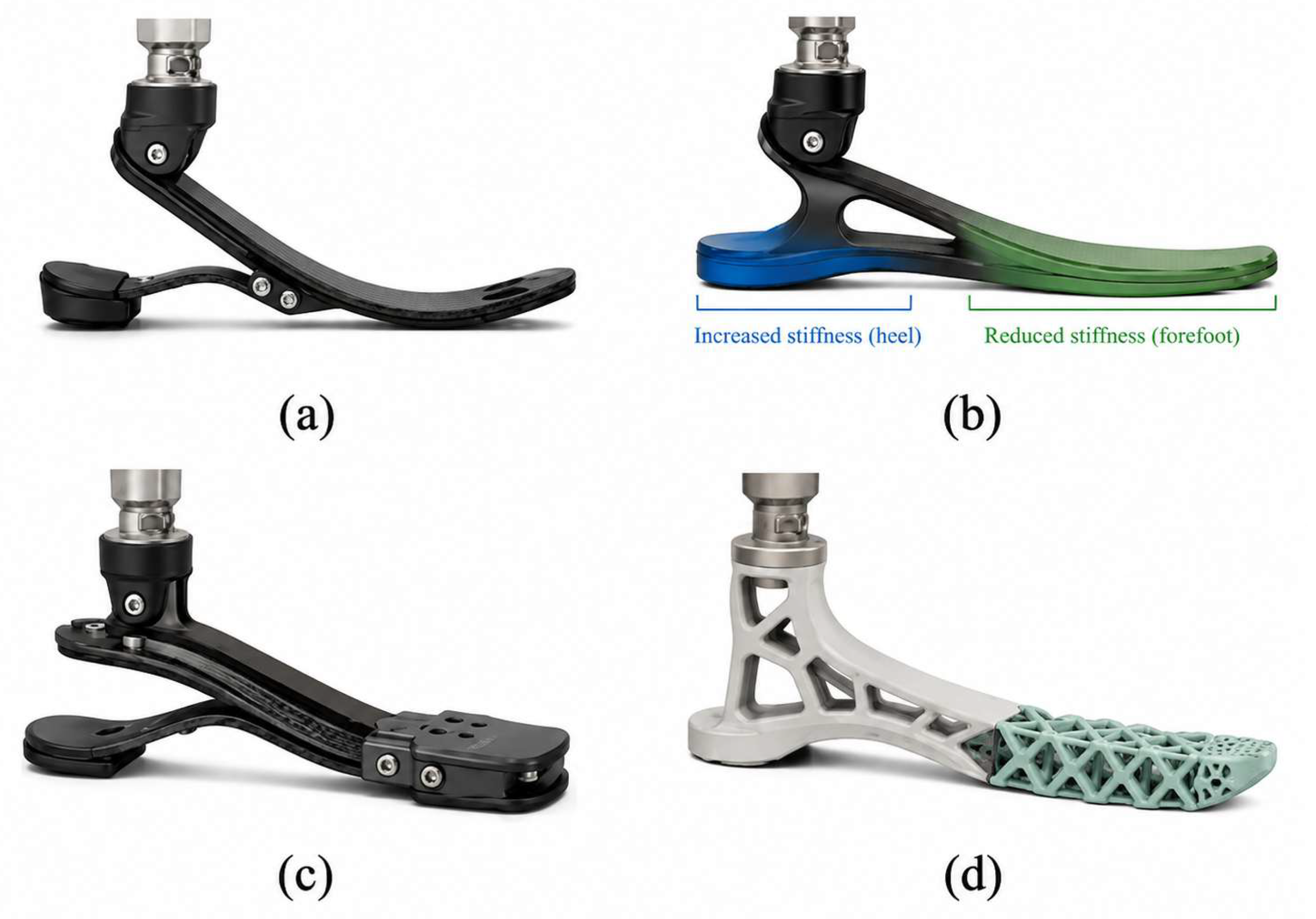
The toe segment receives particular attention in the literature because it plays a major role in rollover and push-off. The forefoot must bear load while delivering controlled bending close to natural foot biomechanics. Designs employing nonlinear stiffness, curvilinear geometry, dedicated flexion zones, and auxetic structures have been proposed to meet this requirement [6]. Examples of contemporary prosthetic foot designs are presented in Figure 1.
Figure 1.
Overview of various prosthetic foot designs. (a) Energy Storage and Return (ESAR) foot; (b) Variable stiffness foot, indicating zones of increased stiffness at the heel and reduced stiffness at the forefoot; (c) Modular prosthetic foot; (d) 3D-printed foot with a flexible toe segment.
This review establishes that a functional prosthetic sole must combine load-bearing strength, controlled forefoot flexibility, energy storage and return, manufacturability, and the option of individual adaptation. A comparative analysis of the reviewed solutions is summarized in Table 1.
Table 1.
Comparative analysis of scientific solutions for prosthetic feet.
3. Materials and Methods
3.1. Material Selection and Justification of the Design Concept
Material selection received particular attention because the foot module must simultaneously deliver sufficient strength, vertical-load resistance, elastic deformation, and manufacturability. Multi-material additive manufacturing combines different mechanical functions—stiffness, compliance, cushioning, and energy return—within a single part [12]. This approach is especially relevant for a prosthetic foot, in which the heel, midfoot, and forefoot serve distinct biomechanical roles.
Carbon-filled nylon PAHT-CF (Bambu Lab, Shenzhen, China) was selected for the load-bearing portion of the sole. PAHT-CF offers higher stiffness and strength than conventional FDM/FFF thermoplastics. Mechanical studies of 3D-printed (Bambu Lab, Shenzhen, China) carbon-filled nylons show that performance depends strongly on infill density, print orientation, nozzle temperature, and interlayer adhesion [13]. PAHT-CF therefore suits the regions of the sole that carry the main vertical load and must retain geometric stability in service.
TPU 95A (Bambu Lab, Shenzhen, China) was selected for the flexible toe segment because of its high elasticity, large elongation at break, and reversible deformation. Studies of 3D-printed TPU structures confirm that such materials perform well in compliant, cushioning, and energy-absorbing components [14,15]. TPU 95A is characterized by a Shore hardness of 95A, tensile strength of approximately 35–50 MPa, elongation at break exceeding 400%, and high fatigue resistance under cyclic deformation. In addition, the material demonstrates good impact absorption and elastic recovery, making it suitable for repeated forefoot bending during gait. These characteristics allow TPU 95A to function as a compliant internal element capable of distributing stresses and improving rollover smoothness in the prosthetic sole.
The proposed design implements functional material distribution: PAHT-CF forms the rigid load-bearing frame, while TPU 95A forms the toe-segment elastic element responsible for controlled bending. This combination unites the strength and dimensional stability of the load path with the compliance of the forefoot, improving the biomechanical efficiency of the sole. The principal properties and roles of the selected materials are summarized in Table 2.
Table 2.
Main properties and functional roles of the selected materials.
The prosthetic sole geometry was developed to reflect the biomechanical functions of the human foot. The part comprises a heel zone, a midfoot load-bearing region, and a forefoot toe segment. The heel and midfoot deliver support, while the forefoot delivers controlled bending during rollover and push-off.
The total foot length is approximately 250 mm, matching the average anthropometric parameters of an adult user. The rear height is approximately 31.5 mm, and the forefoot toe segment length is approximately 83 mm. This proportion provides adequate ground-contact area while clearly delimiting the functional flexion zone in the forefoot.
Unlike fully rigid prosthetic feet, the toe segment in the proposed design is not a passive extension of the sole; it acts as an elastic element. The outer toe-segment shell remains connected to the rigid PAHT-CF frame, while the inner TPU 95A zone provides local compliance. As a result, applied load produces distributed deformation rather than a sharp bend at a single point.
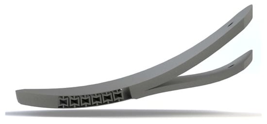
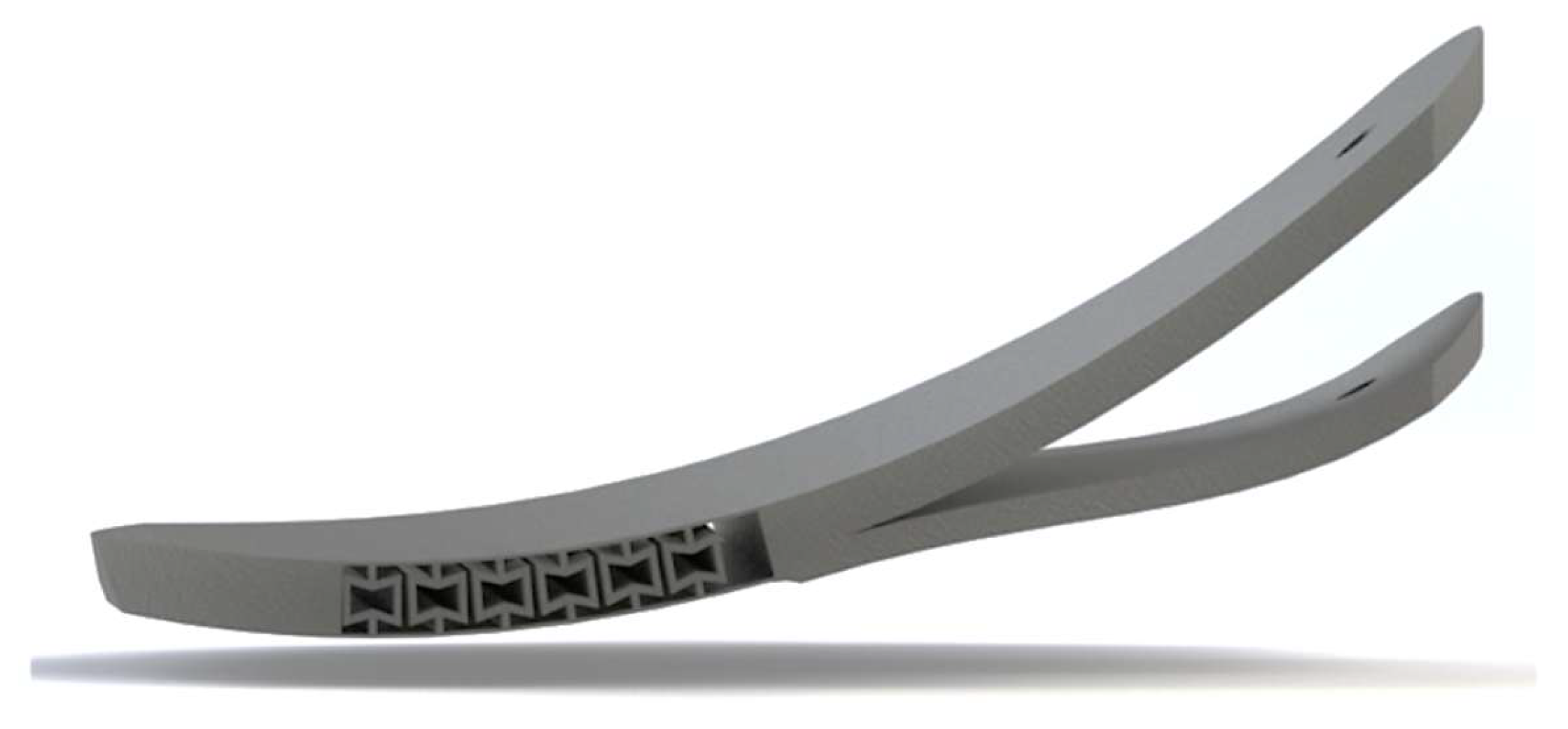
The 3D model of the developed prosthetic sole with a flexible toe segment is presented in Figure 2.
Figure 2.
3D model of the developed prosthetic sole with a flexible toe segment.
Figure 3 shows the structural scheme of the flexible toe segment, including the overall foot geometry, the 83 mm forefoot flexion zone, lattice-based TPU 95A structures, and the principal bending direction during rollover. The scheme also illustrates the separation between the rigid PAHT-CF load-bearing frame and the compliant TPU region responsible for controlled elastic deformation.
Figure 3.
Structural scheme of the flexible toe segment with an internal TPU 95A zone.
3.2. Prototype Fabrication by 3D Printing
The prototype was fabricated by fused deposition modelling (FDM/FFF). PAHT-CF served as the load-bearing portion, and TPU 95A served as the flexible toe segment. This workflow follows current trends in multi-material additive manufacturing, where different materials are co-printed to achieve a target combination of mechanical properties [12].
The mechanical performance of 3D-printed parts depends not only on the material but also on print parameters. Layer height, infill density, build orientation, perimeter count, nozzle temperature, and interlayer adhesion are particularly influential. For carbon-filled nylon, stable print temperature and strong interlayer bonding are critical, because interlayer defects reduce mechanical strength [13].
For TPU 95A, retaining post-print elasticity is the key concern. The flexible region was designed with a lattice or internal deformable structure to enhance compliance without losing load-bearing capacity. Cell geometry and print parameters strongly influence the compression and deformation response of TPU lattices [15].
Print parameters were tailored to the functional role of each zone. The PAHT-CF load-bearing portion used higher infill density, more perimeters, and a higher nozzle temperature to maximize strength and interlayer adhesion. The TPU 95A toe segment used lower infill density and reduced print speed to preserve elasticity and deliver controlled forefoot deformation. The indicative print parameters are listed in Table 3.
Table 3.
Indicative 3D-printing parameters of the prototype.
3.3. Numerical Simulation in SolidWorks Simulation
Numerical simulations in SolidWorks Simulation 2022 provided a preliminary assessment of the strength and deformation behavior of the developed sole. Finite element analysis at the design stage identifies regions of maximum deformation and verifies the stiffness distribution along the construction.
A static finite element scheme was set up. A 400 N vertical load was applied to the foot support surface. The analyzed quantities included total displacement, the deformation pattern of the forefoot, the load distribution between the load-bearing portion and the toe segment, and the preservation of overall geometry.
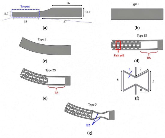
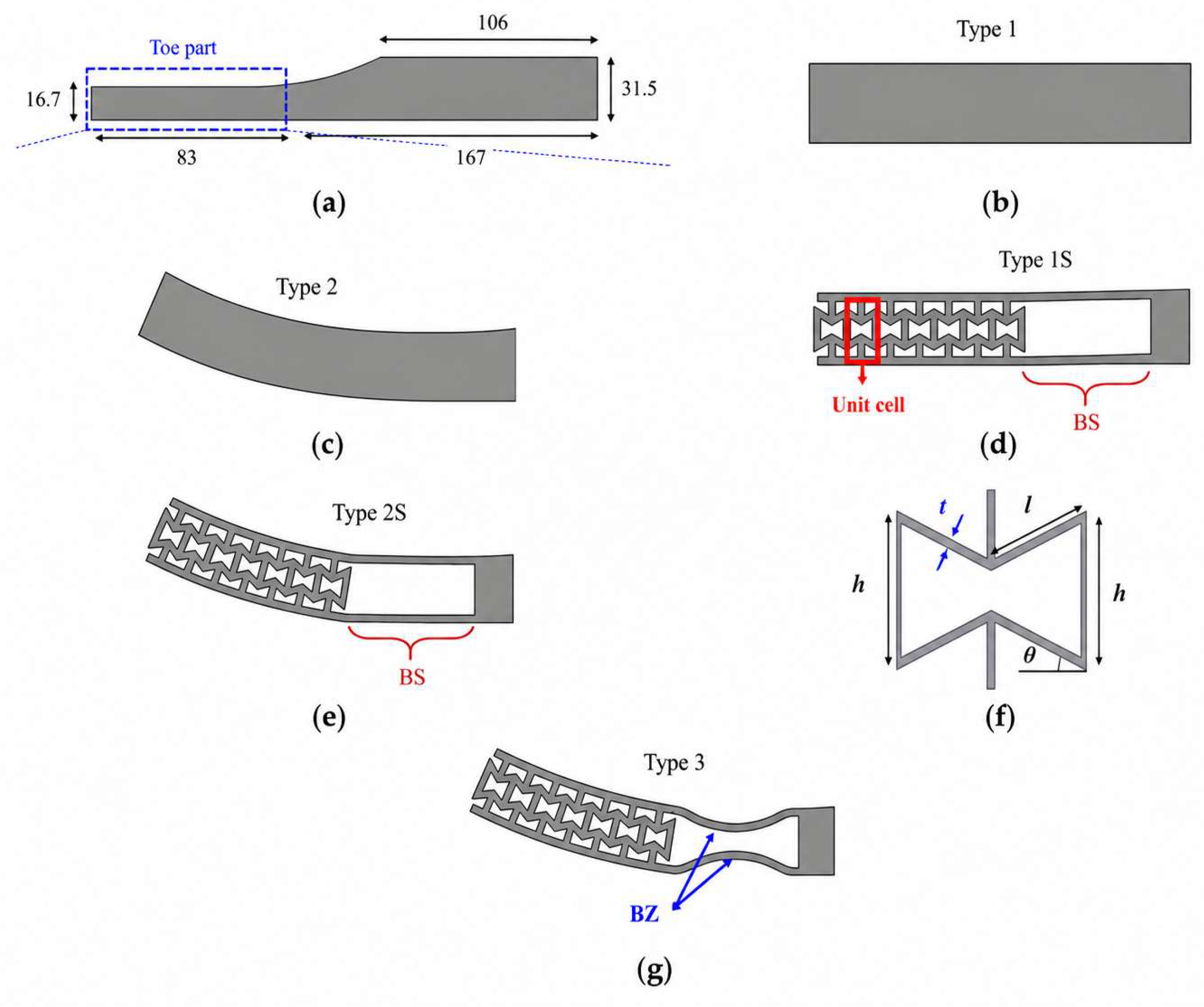
The forefoot must remain more compliant than the heel and midfoot regions. A successful simulation outcome therefore concentrates the maximum displacement in the toe segment, while the load-bearing portion retains stability. The numerical results for the prosthetic sole are presented in Figure 4.
Figure 4.
Geometric dimensions and design configurations of the investigated structure. (a) Overall dimensions of the base model indicating the toe part region; (b) Type 1: solid straight design; (c) Type 2: solid curved design; (d) Type 1S: straight design incorporating a cellular structure and a solid section (BS); (e) Type 2S: curved design incorporating a cellular structure and a solid section (BS); (f) Schematic and geometric parameters of the unit cell; (g) Type 3: curved design with a cellular structure and a modified narrow zone (BZ).
The principal study conditions, namely the analysis type, the magnitude and direction of the applied load, and the target output parameters, were defined to ensure correct interpretation of the analysis. Displacement distribution along the sole length served as the primary criterion, because it indicates whether the deformation behavior matches the intended function. The forefoot toe segment must develop controlled compliance while the midfoot and heel regions must remain structurally stable. The principal numerical-simulation conditions are summarized in Table 4.
Table 4.
Numerical simulation conditions.
4. Results and Discussion
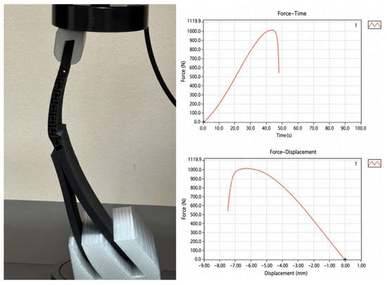
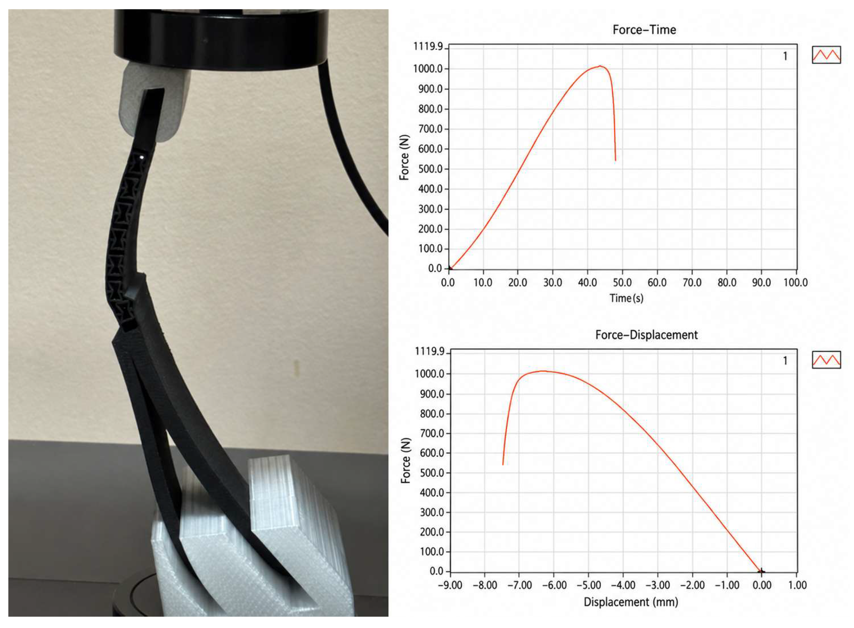
After fabrication, the prosthetic-sole specimen was subjected to static compression testing using a WDW-10 computer-controlled electronic universal testing machine (Jinan Hensgrand Instrument Co., Ltd., Jinan, China; maximum load capacity: 10 kN). The specimen was placed vertically between the press plates. The load was ramped progressively to 1000 N, a value close to realistic stance-phase loading. Maximum displacement, the appearance of cracks or fractures, and any residual plastic deformation after unloading were recorded.
Such testing is a primary engineering check of structural performance. It does not replace cyclic testing or biomechanical gait validation but verifies the load-bearing capacity of the prototype and confirms the chosen design concept. The hydraulic-press test of the printed specimen is shown in Figure 5.
Figure 5.
Hydraulic-press test of the printed prosthetic-sole specimen.
The design produced a prosthetic sole with functionally separated zones: the load-bearing portion absorbs vertical load while the forefoot toe segment delivers controlled bending during rollover. The concept brings the prosthetic-sole behavior closer to natural foot biomechanics, especially during the toe-off phase, when the forefoot drives push-off from the support surface. The final form of the developed sole is shown in Figure 6.
Figure 6.
Final form of the developed prosthetic sole.
Placing TPU inside the toe segment delivers a controlled forefoot bend. Under load, the outer frame absorbs the dominant forces while the inner elastic zone produces smooth deformation without sharp stress concentrations. This behavior is critical for durability, because cyclic walking commonly initiates failure at stress-concentration sites in prosthetic components.
The resulting toe segment serves several functions simultaneously: it provides forefoot flexibility, contributes to cushioning, supports a smoother rollover, and enables partial energy return during push-off. Compared with a fully rigid sole, the hybrid concept is biomechanically more justified because it lowers impact loading and improves adaptation to the support surface.
Numerical simulations in SolidWorks Simulation evaluated the deformation pattern of the prosthetic sole under vertical load and verified the stiffness distribution between the load-bearing portion and the flexible toe segment.
A 400 N vertical load applied to the foot support surface produced the largest deformation in the forefoot, that is, in the zone designed for bending and rollover. The maximum tip displacement reached approximately 25 mm, confirming that the forefoot is sufficiently compliant to participate in natural gait imitation.
In the toe-segment region, the deformation reached approximately 10 mm. The flexible zone therefore operates within a controlled compliance range: it is neither overly soft nor excessively stiff. Excess forefoot rigidity would degrade rollover, while excess softness would compromise stability and push-off effectiveness.
The midfoot and heel sections showed substantially smaller displacements. The result confirms a correct distribution of mechanical properties along the foot length: the load-bearing zones remain stable, while the forefoot performs the deformable role. The sole therefore exhibits functionally graded behavior, with each region performing a distinct biomechanical task.
Following the simulations, a physical specimen was fabricated by 3D printing and tested on a hydraulic press to evaluate its strength and deformation response. The test assessed the ability of the construction to withstand vertical static loading representative of stance-phase loads.
The specimen was mounted vertically to reproduce axial foot-module loading. The applied load was ramped progressively to 1000 N. The specimen exhibited controlled elastic behavior with no signs of fracture. The maximum displacement reached approximately 7 mm. After unloading, the foot recovered its initial shape; no residual plastic deformation was observed visually.
These results confirm that the printed construction delivers adequate load-bearing capacity for substantial vertical loads. The deformation was reversible, an essential feature for a prosthetic sole subjected to repeated cyclic loading. The absence of damage at 1000 N validates PAHT-CF as the load-bearing material.
Inspection of the prototype confirmed that the proposed sole combines the required strength and flexibility. PAHT-CF preserved the overall shape and absorbed the dominant load, while TPU produced local compliance in the toe-segment region.
Crucially, this flexibility was achieved through material and geometry rather than a discrete mechanical hinge. The result simplifies the construction, reduces the number of moving joints, and lowers the risk of mechanical wear. For prosthetic devices, a simple and manufacturable architecture is also easier to fabricate, maintain, and adapt to individual users.
The simulation and the experiment agree with the engineering rationale. The simulation concentrated maximum deformation in the forefoot, and the physical specimen withstood 1000 N without failure. The construction therefore achieves both forefoot flexibility and load-bearing strength. The combined results are summarized in Table 5.
Table 5.
Combined results of numerical simulation and experimental testing.
The main limitation of the present study is that testing covered only static vertical loading. Long-term cyclic testing, fatigue analysis, and biomechanical gait testing fall outside the scope of this work. Furthermore, the print parameters require further optimization, because the strength and deformation behavior of FDM/FFF parts depend strongly on print orientation, infill, nozzle temperature, layer height, and interlayer adhesion. The reported results should therefore be interpreted as a first engineering evaluation of the proposed design.
5. Conclusions
This work designed and evaluated a prosthetic sole with a flexible toe segment fabricated by 3D printing. The literature review confirmed that prosthetic-foot performance depends on the synergy of load-bearing strength, controlled forefoot flexibility, cushioning, and energy return during push-off.
Based on this analysis, the authors propose a sole concept in which a rigid PAHT-CF frame absorbs the dominant load and preserves shape, while an internal TPU 95A zone forms an elastic toe segment that mimics the natural bending of the human forefoot. The concept enables toe-segment mobility without complex articulated mechanisms or active actuators.
Numerical simulations in SolidWorks Simulation 2022 confirmed that the maximum deformation occurs in the forefoot, the functional zone responsible for rollover and push-off. Under a 400 N load, the maximum tip displacement reached approximately 25 mm and the toe-segment deformation reached approximately 10 mm, demonstrating controlled compliance.
Hydraulic-press testing of the printed specimen demonstrated that the prosthetic sole withstands a vertical load of up to 1000 N with a maximum displacement of approximately 7 mm without fracture or residual plastic deformation. The construction therefore offers a balanced combination of strength, flexibility, and manufacturability.
Future work will include cyclic testing of the prototype, optimization of the toe-segment geometry, evaluation of how individual print parameters affect strength and energy return, and biomechanical testing under simulated gait loading.
Author Contributions
Conceptualization, T.S. and Y.N. (Yerkebulan Nurgizat); methodology, T.S., A.O. and D.R.; software, A.O., D.R. and Y.N. (Yernur Nurbekov); validation, T.S., A.O., D.R., Y.N. (Yerkebulan Nurgizat) and Y.N. (Yernur Nurbekov); formal analysis, Y.N. (Yerkebulan Nurgizat), N.Z. and A.S.; investigation, T.S. and K.O.; resources, Y.N. (Yerkebulan Nurgizat) and K.O.; data curation, A.O., D.R. and Y.N. (Yernur Nurbekov); writing—original draft preparation, T.S., A.O. and D.R.; writing—review and editing, Y.N. (Yerkebulan Nurgizat), N.Z. and A.S.; visualization, A.O., D.R. and Y.N. (Yernur Nurbekov); supervision, Y.N. (Yerkebulan Nurgizat) and K.O.; project administration, Y.N. (Yerkebulan Nurgizat); funding acquisition, Y.N. (Yerkebulan Nurgizat). All authors have read and agreed to the published version of the manuscript.
Funding
This research was funded by the Science Committee of the Ministry of Science and Higher Education of the Republic of Kazakhstan within the framework of the program BR24992820.
Institutional Review Board Statement
Not applicable.
Informed Consent Statement
Not applicable.
Data Availability Statement
The data presented in this study is available on request from the corresponding author.
Conflicts of Interest
The authors declare no conflicts of interest.
Abbreviations
The following abbreviations are used in this manuscript:
| ESAR | Energy-Storage-and-Return |
| FDM | Fused Deposition Modeling |
| FFF | Fused Filament Fabrication |
References
- World Health Organization. Rehabilitation. WHO Fact Sheet. Available online: https://www.who.int/news-room/fact-sheets/detail/rehabilitation (accessed on 30 April 2026).
- World Health Organization; UNICEF. Global Report on Assistive Technology; World Health Organization: Geneva, Switzerland, 2022. [Google Scholar]
- World Health Organization. WHO Standards for Prosthetics and Orthotics; World Health Organization: Geneva, Switzerland, 2017. [Google Scholar]
- Zelik, K.E.; Honert, E.C. Ankle and foot power in gait analysis: Implications for science, technology and clinical assessment. J. Biomech. 2018, 75, 1–12. [Google Scholar] [CrossRef] [Scilit]
- Honert, E.C.; Bastas, G.; Zelik, K.E. Effect of toe joint stiffness and toe shape on walking biomechanics. Bioinspir. Biomim. 2018, 13, 066007. [Google Scholar] [CrossRef] [Scilit]
- Um, H.-J.; Kim, H.-S.; Hong, W.; Kim, H.-S.; Hur, P. Design of 3D printable prosthetic foot to implement nonlinear stiffness behavior of human toe joint based on finite element analysis. Sci. Rep. 2021, 11, 19731. [Google Scholar] [CrossRef] [Scilit]
- South, B.J.; Fey, N.P.; Bosker, G.; Neptune, R.R. Manufacture of energy storage and return prosthetic feet using selective laser sintering. J. Biomech. Eng. 2010, 132, 015001. [Google Scholar] [CrossRef] [Scilit]
- Fey, N.P.; Klute, G.K.; Neptune, R.R. The influence of energy storage and return foot stiffness on walking mechanics and muscle activity in below-knee amputees. Clin. Biomech. 2011, 26, 1025–1032. [Google Scholar] [CrossRef] [Scilit]
- Rochlitz, B.; Pammer, D. Design and analysis of 3D printable foot prosthesis. Period. Polytech. Mech. Eng. 2017, 61, 282–287. [Google Scholar] [CrossRef] [Scilit]
- Bowen, J.; Hausselle, J.; Gonzalez, R. A low-cost customizable prosthetic foot with energy return capabilities. Prosthet. Orthot. Open J. 2018, 2, 1–5. [Google Scholar]
- Al Thahabi, A.R.N.; Martulli, L.M.; Rollo, G.; Romanò, J.; Sorrentino, A.; Garavaglia, L.; Pittaccio, S.; Lavorgna, M.; Gruppioni, E.; Bernasconi, A. Numerical design and experimental validation of a 3D-printed composite energy-storage-and-return prosthetic foot. Compos. Struct. 2025, 358, 118907. [Google Scholar] [CrossRef] [Scilit]
- Nazir, A.; Gokcekaya, O.; Billah, K.M.M.; Ertugrul, O.; Jiang, J.; Sun, J.; Hussain, S. Multi-material additive manufacturing: A systematic review of design, properties, applications, challenges, and 3D printing of materials and cellular metamaterials. Mater. Des. 2023, 226, 111661. [Google Scholar] [CrossRef] [Scilit]
- Zárybnická, L.; Machotová, J.; Pagáč, M.; Rychlý, J.; Vykydalová, A. The effect of filling density on flammability and mechanical properties of 3D-printed carbon fiber-reinforced nylon. Polym. Test. 2023, 120, 107944. [Google Scholar] [CrossRef] [Scilit]
- Khatri, N.R.; Egan, P.F. Energy absorption of 3D printed ABS and TPU multimaterial honeycomb structures. 3D Print. Addit. Manuf. 2024, 11, e840–e850. [Google Scholar] [CrossRef] [Scilit]
- de la Rosa, S.; Mayuet, P.F.; Silva, C.S.; Sampaio, Á.M.; Rodríguez-Parada, L. Design and characterization of 3D-printed TPU-based lattice structures. Application to methodology for the design of personalized therapeutic products. Rapid Prototyp. J. 2024, 30, 72–86. [Google Scholar] [CrossRef] [Scilit]



Disclaimer/Publisher’s Note: The statements, opinions and data contained in all publications are solely those of the individual author(s) and contributor(s) and not of MDPI and/or the editor(s). MDPI and/or the editor(s) disclaim responsibility for any injury to people or property resulting from any ideas, methods, instructions or products referred to in the content. |
© 2026 by the authors. Licensee MDPI, Basel, Switzerland. This article is an open access article distributed under the terms and conditions of the Creative Commons Attribution (CC BY) license.